EP1454565A1 - Un dispositif rétractable pour un support d'étagère dans un meuble - Google Patents
Un dispositif rétractable pour un support d'étagère dans un meuble Download PDFInfo
- Publication number
- EP1454565A1 EP1454565A1 EP04075270A EP04075270A EP1454565A1 EP 1454565 A1 EP1454565 A1 EP 1454565A1 EP 04075270 A EP04075270 A EP 04075270A EP 04075270 A EP04075270 A EP 04075270A EP 1454565 A1 EP1454565 A1 EP 1454565A1
- Authority
- EP
- European Patent Office
- Prior art keywords
- pin
- casing
- groove
- working element
- operating position
- Prior art date
- Legal status (The legal status is an assumption and is not a legal conclusion. Google has not performed a legal analysis and makes no representation as to the accuracy of the status listed.)
- Withdrawn
Links
- 238000012423 maintenance Methods 0.000 claims abstract description 10
- 238000010276 construction Methods 0.000 claims description 5
- 238000000465 moulding Methods 0.000 claims description 5
- 210000000988 bone and bone Anatomy 0.000 claims 1
- 238000006073 displacement reaction Methods 0.000 claims 1
- 239000000463 material Substances 0.000 description 3
- 241000251468 Actinopterygii Species 0.000 description 2
- 238000004519 manufacturing process Methods 0.000 description 2
Images


Classifications
-
- A—HUMAN NECESSITIES
- A47—FURNITURE; DOMESTIC ARTICLES OR APPLIANCES; COFFEE MILLS; SPICE MILLS; SUCTION CLEANERS IN GENERAL
- A47B—TABLES; DESKS; OFFICE FURNITURE; CABINETS; DRAWERS; GENERAL DETAILS OF FURNITURE
- A47B96/00—Details of cabinets, racks or shelf units not covered by a single one of groups A47B43/00 - A47B95/00; General details of furniture
- A47B96/06—Brackets or similar supporting means for cabinets, racks or shelves
- A47B96/066—Supporting means received within an edge of the shelf
-
- F—MECHANICAL ENGINEERING; LIGHTING; HEATING; WEAPONS; BLASTING
- F16—ENGINEERING ELEMENTS AND UNITS; GENERAL MEASURES FOR PRODUCING AND MAINTAINING EFFECTIVE FUNCTIONING OF MACHINES OR INSTALLATIONS; THERMAL INSULATION IN GENERAL
- F16B—DEVICES FOR FASTENING OR SECURING CONSTRUCTIONAL ELEMENTS OR MACHINE PARTS TOGETHER, e.g. NAILS, BOLTS, CIRCLIPS, CLAMPS, CLIPS OR WEDGES; JOINTS OR JOINTING
- F16B12/00—Jointing of furniture or the like, e.g. hidden from exterior
- F16B12/10—Jointing of furniture or the like, e.g. hidden from exterior using pegs, bolts, tenons, clamps, clips, or the like
- F16B12/12—Jointing of furniture or the like, e.g. hidden from exterior using pegs, bolts, tenons, clamps, clips, or the like for non-metal furniture parts, e.g. made of wood, of plastics
- F16B12/24—Jointing of furniture or the like, e.g. hidden from exterior using pegs, bolts, tenons, clamps, clips, or the like for non-metal furniture parts, e.g. made of wood, of plastics using separate pins, dowels, or the like
-
- F—MECHANICAL ENGINEERING; LIGHTING; HEATING; WEAPONS; BLASTING
- F16—ENGINEERING ELEMENTS AND UNITS; GENERAL MEASURES FOR PRODUCING AND MAINTAINING EFFECTIVE FUNCTIONING OF MACHINES OR INSTALLATIONS; THERMAL INSULATION IN GENERAL
- F16B—DEVICES FOR FASTENING OR SECURING CONSTRUCTIONAL ELEMENTS OR MACHINE PARTS TOGETHER, e.g. NAILS, BOLTS, CIRCLIPS, CLAMPS, CLIPS OR WEDGES; JOINTS OR JOINTING
- F16B5/00—Joining sheets or plates, e.g. panels, to one another or to strips or bars parallel to them
- F16B5/06—Joining sheets or plates, e.g. panels, to one another or to strips or bars parallel to them by means of clamps or clips
- F16B5/0607—Joining sheets or plates, e.g. panels, to one another or to strips or bars parallel to them by means of clamps or clips joining sheets or plates to each other
- F16B5/0614—Joining sheets or plates, e.g. panels, to one another or to strips or bars parallel to them by means of clamps or clips joining sheets or plates to each other in angled relationship
Definitions
- the present invention relates to a disappearing shelf-supporting device for furniture.
- Devices for shelf support in furniture which are adapted to be inserted in an appropriate seat on the shelf edge and are provided with a pin elastically jutting out of the edge for fitting into a hole in the wall of the piece of furniture.
- These devices have construction expedients capable of enabling the pin to keep two steady positions, a rest and an operating positions respectively. In the first position the pin is retracted in the shelf edge and in the second it projects from the shelf edge.
- a further important drawback of the known art resides in that known devices are hardly manoeuvrable without use of a tool (a screwdriver for example) and this makes positioning of the shelves utilising such devices less prompt.
- a disappearing shelf-supporting device for furniture which is designed to be housed on the edge of a shelf and comprises a casing having a seat in which a pin is housed, which pin axially slides in the seat between an operating position, at which the pin has its front portion projecting from a front wall of the casing and out of the shelf edge, and a non-operating position at which the pin is retracted in its seat for not projecting from the shelf edge, a working element laterally projects from the pin and slides in a groove in the casing, which groove is open on a side face of the casing to enable manual operation of the pin between the two positions of same, fitting means being further present in the casing for an unstable maintenance of the pin in the retracted position, characterised in that the fitting means for an unstable maintenance of the pin in the retracted position is disposed between the side wall of said groove and said working element sliding therein.
- a disappearing shelf-supporting device for furniture is shown in Fig. 1 and generally denoted at 10, which device is designed to be housed in a cavity 11 on the edge of a shelf 12.
- the shelf support comprises a casing 13 with a seat 14 in which a pin 15 is housed which pin axially slides in the seat between an operating position at which the pin has its front portion projecting from a front wall of the casing and out of the shelf edge, and a non-operating position at which the pin is retracted in the seat for not projecting from the shelf edge.
- the operating and non-operating positions of the pin are shown in chain line and solid line respectively in Fig. 2.
- two pairs of shelf supports disposed on opposite edges of a shelf can bear the shelf in a piece of furniture by fitting the pins in an operating position into appropriate seats or holes formed in the inner wall of the piece of furniture.
- a working element 16 laterally projects from the pin and slides in a groove 17 in the casing that is open on a side face 18 of the casing itself.
- This side face 18 is designed to set itself parallel to the lower surface of the shelf to project therefrom.
- the working element 16 thus allows manual operation of the pin between the two positions thereof.
- a screw-driver can be for example employed which fits into a hollow advantageously formed in the end of the element itself.
- the groove and working element advantageously have a generally T-shaped cross section with the "T" foot directed towards the pin axis.
- fitting means for an unstable maintenance of the pin in the retracted position, so that the pin does not inopportunely move from the non-operating position to the operating position (and, if wished, from the operating position to the non-operating position) without the working element being acted upon.
- the pin can be advantageously urged to the operating position by means of a helical spring 19 placed at the bottom of the seat to act rearwardly of the pin.
- the fitting means must efficiently counteract the spring thrust.
- the helical spring has a lower thrust force than the force required for overcoming the fitting means.
- the fitting means 20 for an unstable maintenance of the pin in the retracted position is disposed between the side wall of groove 17 and element 16 sliding therein.
- this fitting means comprises two projections 20 facing themselves on opposite side walls of the groove and jutting out in the groove to interfere with element 16 and during sliding of same along the groove.
- projections 20 are extended in a direction normal to the sliding direction of the element in the groove and each interfere with a front corner of the working element, as clearly shown in Fig. 2.
- the projections can be stepped over when a thrusting action is manually exerted on the working element due to the elasticity of the surfaces coming into contact with each other.
- This elasticity can be merely obtained by suitably selecting the plastic material for manufacture of the casing.
- the casing can be formed with a cavity 21 behind each of the side walls carrying the projections. Thinning of the wall thus provides an elastic support for the projections.
- the cavities open on the side face 18 of the casing. In this way they can be easily obtained during moulding of the casing.
- the pin seat 14 and groove 17 are open on the front face 23 of the casing so as to allow the first axial introduction of the pin into the seat in the casing. Also present in the casing is stop limit means preventing a subsequent movement of the pin beyond the operating position, so that said pin cannot unintentionally fully come out of the casing and separate therefrom.
- the stop limit means is advantageously embodied by "fish bone-shaped" teeth 22, disposed close to the groove opening on the front face of the casing and directed to the groove inside. Due to the inclination and size of the teeth, passage of the working element is allowed when the device is assembled pushing the pin into the seating. After that, the inner edge of the teeth forms a stop limit against which the front corner of the working element strikes (as shown in chain line in Fig. 3), so as to prevent the pin from coming out beyond the operating position.
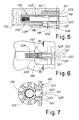
- FIG. 5 A second embodiment of a disappearing shelf-supporting device for furniture is shown in Fig. 5 and generally denoted at 110, which device is designed to be housed in a cavity 111 on the edge of a shelf 112.
- the shelf support comprises a casing 113 with a seat 114 in which a pin 115 is housed which pin axially slides in the seat between an operating position at which the pin has its front portion projecting from a front wall of the casing and out of the shelf edge, and a non-operating position at which the pin is retracted in the seat for not projecting from the shelf edge.
- the operating and non-operating positions of the pin are shown in chain line and solid line, respectively.
- two pairs of shelf supports disposed on opposite edges of a shelf can bear the shelf in a piece of furniture by fitting the pins in an operating position into appropriate seats or holes formed in the inner wall of the piece of furniture.
- a working element 116 laterally projects from the pin and slides in a groove 117 in the casing that is open on a side face 118 of the casing itself.
- This side face 118 is designed to set itself parallel to the lower surface of the shelf to project therefrom.
- the groove and working element advantageously have a generally T-shaped cross-section with the "T" foot directed towards the pin axis.
- the working element 116 terminates on the side face 118 with a slider 124 advantageously having a finely undulated or transversely knurled surface, extending parallel to the side face to be manoeuvrable with one finger to make the pin slide between the two positions thereof.
- the slider extends rearwardly, in an L-shaped conformation with respect to the working element, in a direction parallel to the pin axis, with an undulated surface slightly projecting from the device face 118, so as to allow easy operation of same.
- the slider protection between the two portions of wall 118 makes an accidental movement for unlocking the device in the operating position less likely to occur.
- the groove 117 is open rearwardly on the edge 125 of surface 118 and the rear portion of the slider is elongated to such an extent that when the pin is in an operating position the slider is fully contained between the two body portions defining surface 118 (as viewed in chain line in Fig. 1), whereas when the pin is in a non-operating position, the slider projects, by its rear portion, beyond the rear edge 125 of wall 118.
- the slider In the operating position advantageously the slider substantially covers the whole groove 117.
- fitting means for an unstable maintenance of the pin in the retracted position, so that the pin does not inopportunely move from the non-operating position to the operating position (and, if wished, from the operating position to the non-operating position) without the working element being acted upon.
- the pin can be advantageously urged to the operating position by means of a helical spring 119 placed at the bottom of the seat to act rearwardly of the pin.
- the fitting means must efficiently counteract the spring thrust.
- the helical spring has a lower thrust force than the force required for overcoming the fitting means.
- the fitting means 120 for an unstable maintenance of the pin in the retracted position is disposed between the side wall of groove 117 and element 116 sliding therein.
- this fitting means comprises two projections 120 facing each other on opposite side walls of the groove and jutting out in the groove to interfere with element 116 and during sliding of same along the groove.
- projections 120 are extended in a direction normal to the sliding direction of the element in the groove and each interfere with a front corner of the working element, as clearly shown in Figs. 5 and 6. These projections 120 stop towards surface 118 to allow transit of the slider and remain under the latter.
- the projections can be stepped over when a thrusting action is manually exerted on the working element due to the elasticity of the surfaces coming into contact with each other.
- This elasticity can be merely obtained by suitably selecting the plastic material for manufacture of the casing.
- the casing can be formed with a cavity 121 behind each of the side walls carrying the projections. Thinning of the wall thus provides an elastic support for the projections.
- the cavities open on the side face 118 of the casing. In this way they can be easily obtained during moulding of the casing.
- the pin seat 114 and groove 117 are open on the front face 123 of the casing so as to allow the first axial introduction of the pin into the seat in the casing. Also present in the casing is stop limit means preventing a subsequent movement of the pin beyond the operating position, so that said pin cannot unintentionally fully come out of the casing and separate therefrom.
- the stop limit means is advantageously embodied by "fish bone-shaped" teeth 122, disposed close to the groove opening on the front face of the casing and directed to the groove inside.
- teeth 122 stop before reaching the bridge 126 terminating ahead of groove 117 to strengthen the body structure of the device.
- the space between the bridge 126 and teeth 122 is adapted to allow passage of slider 124 during assembling of the device.
- the shelf-supporting device can be made up of two pieces alone (three pieces, if the spring is provided).
- the proposed structure for the casing body allows the casing to be made of one piece construction, being moulded from a plastic material, and moulding is very simple and cheap.
- the mould can be made in such a manner that it has the closure of the two halves in a junction plane shown in chain dot line in Fig. 1, with a single short-stroke side carriage to make the groove 17, 117 (also forming the inner edges of teeth 22, 122) and cavities 21, 121.
- slider 124 can be made as a separate piece fastened to or fitted into the working element 116.
Landscapes
- Engineering & Computer Science (AREA)
- General Engineering & Computer Science (AREA)
- Mechanical Engineering (AREA)
- Furniture Connections (AREA)
- Drawers Of Furniture (AREA)
Applications Claiming Priority (4)
| Application Number | Priority Date | Filing Date | Title |
|---|---|---|---|
| ITMI20030052 ITMI20030052U1 (it) | 2003-02-12 | 2003-02-12 | Dispositivo a scomparsa per il supporto di ripiano in mobili |
| ITMI20030052 | 2003-02-12 | ||
| ITMI20030231 ITMI20030231U1 (it) | 2003-05-14 | 2003-05-14 | Dispositivo a scomparsa a cursore per il supporto di ripiani in mobili |
| ITMI20030231 | 2003-05-14 |
Publications (1)
| Publication Number | Publication Date |
|---|---|
| EP1454565A1 true EP1454565A1 (fr) | 2004-09-08 |
Family
ID=32827136
Family Applications (1)
| Application Number | Title | Priority Date | Filing Date |
|---|---|---|---|
| EP04075270A Withdrawn EP1454565A1 (fr) | 2003-02-12 | 2004-01-30 | Un dispositif rétractable pour un support d'étagère dans un meuble |
Country Status (3)
| Country | Link |
|---|---|
| US (1) | US6986488B2 (fr) |
| EP (1) | EP1454565A1 (fr) |
| CN (1) | CN100415143C (fr) |
Cited By (1)
| Publication number | Priority date | Publication date | Assignee | Title |
|---|---|---|---|---|
| EP2762038A1 (fr) | 2013-01-22 | 2014-08-06 | Accessorio SRL in Liquidazione | Support d'étagère encastré destiné à supporter une étagère d'un meuble et étagère comprenant ledit dispositif |
Families Citing this family (20)
| Publication number | Priority date | Publication date | Assignee | Title |
|---|---|---|---|---|
| DE502006006696D1 (de) * | 2005-03-04 | 2010-05-27 | Steelcase Werndl Ag | Regalsystem |
| US20070284983A1 (en) * | 2006-06-12 | 2007-12-13 | Wayner Robert C | Shelf support pin arrangement |
| IL183736A (en) * | 2007-06-07 | 2012-05-31 | Spiral Supports Ltd | Shelf support |
| ATE509551T1 (de) | 2008-10-14 | 2011-06-15 | Livenza Ferramenta Srl | Verbesserte befestigungsvorrichtung für möbelregalbretter |
| GB2494462B (en) * | 2011-09-12 | 2014-09-10 | Christopher Mark Wilkinson | Invisible support structure |
| US9163415B2 (en) * | 2013-12-30 | 2015-10-20 | Joel M Nies | Mantel with hidden mounting assembly |
| CN106231957B (zh) * | 2014-04-14 | 2020-03-03 | 埃费吉布雷韦蒂有限责任公司 | 用于组装/连接模块化家具的零件和装备附件的装置 |
| CN104554980B (zh) * | 2014-12-16 | 2016-09-14 | 上海鸿研物流技术有限公司 | 可折叠式容器 |
| JP6422121B2 (ja) * | 2015-02-23 | 2018-11-14 | 株式会社ハウステック | 棚板の装着構造 |
| CN107536280A (zh) * | 2017-09-29 | 2018-01-05 | 浙江莫霞实业有限公司 | 一种木板置物板能够调节的无把手置物柜 |
| CN107467899A (zh) * | 2017-09-29 | 2017-12-15 | 浙江莫霞实业有限公司 | 一种具有木板置物板的无把手置物柜 |
| CN107568937A (zh) * | 2017-09-29 | 2018-01-12 | 浙江莫霞实业有限公司 | 一种木板置物板能够调节的新型无把手置物柜 |
| CN109008350A (zh) * | 2018-09-05 | 2018-12-18 | 杭州顾家定制家居有限公司 | 一种橱柜滑销式层板托 |
| KR102650975B1 (ko) * | 2018-09-12 | 2024-03-26 | 삼성전자주식회사 | 의류관리기 |
| IT201800020668A1 (it) * | 2018-12-21 | 2020-06-21 | Camar Spa | Sistema di supporto e stabile posizionamento per un ripiano di un mobile |
| US11109679B2 (en) * | 2019-02-15 | 2021-09-07 | Clairson, Inc. | Shelving assembly and hardware |
| IT201900016343A1 (it) * | 2019-09-16 | 2021-03-16 | Leonardo Srl | Dispositivo di supporto perfezionato per ripiani di mobili |
| US20220381280A1 (en) * | 2021-05-31 | 2022-12-01 | Linton Robert Lounds | Fastener |
| KR102472759B1 (ko) * | 2022-04-19 | 2022-12-01 | 주식회사 퍼맥스 | 가구용 선반 |
| KR102577988B1 (ko) * | 2023-03-10 | 2023-09-14 | 주식회사 네오퍼스 | 수납가구용 선반 체결부재 |
Citations (3)
| Publication number | Priority date | Publication date | Assignee | Title |
|---|---|---|---|---|
| WO1996022921A1 (fr) * | 1995-01-27 | 1996-08-01 | David S. Smith Packaging Limited | Dispositif de verrouillage |
| GB2332470A (en) * | 1997-11-12 | 1999-06-23 | R G Trade Supplies And Enginee | Latch member restraint |
| EP1228721A1 (fr) * | 2001-02-05 | 2002-08-07 | Ferramenta Livenza S.r.l. | Support d'étagère pour montage rapide, pour meubles et objets similaires |
Family Cites Families (6)
| Publication number | Priority date | Publication date | Assignee | Title |
|---|---|---|---|---|
| US2252570A (en) * | 1940-06-22 | 1941-08-12 | Modern Steel Equipment Company | Cabinet shelf supporting means |
| US2901806A (en) * | 1956-11-26 | 1959-09-01 | Harry B Henshel | Wrist watch and band coupling |
| US3242868A (en) * | 1964-03-30 | 1966-03-29 | Gen Motors Corp | Fuel pump with improved oil seal assembly |
| US3870266A (en) * | 1973-06-07 | 1975-03-11 | Px Ind Inc | Self-locking shelf support |
| FR2405670A1 (fr) * | 1977-10-14 | 1979-05-11 | Thierache Au Creuset | Equerre pliante |
| CN2289456Y (zh) * | 1997-05-29 | 1998-09-02 | 方伟泽 | 小型便携式多功能组合书柜 |
-
2004
- 2004-01-30 EP EP04075270A patent/EP1454565A1/fr not_active Withdrawn
- 2004-02-02 US US10/770,674 patent/US6986488B2/en not_active Expired - Lifetime
- 2004-02-12 CN CNB200410003992XA patent/CN100415143C/zh not_active Expired - Fee Related
Patent Citations (3)
| Publication number | Priority date | Publication date | Assignee | Title |
|---|---|---|---|---|
| WO1996022921A1 (fr) * | 1995-01-27 | 1996-08-01 | David S. Smith Packaging Limited | Dispositif de verrouillage |
| GB2332470A (en) * | 1997-11-12 | 1999-06-23 | R G Trade Supplies And Enginee | Latch member restraint |
| EP1228721A1 (fr) * | 2001-02-05 | 2002-08-07 | Ferramenta Livenza S.r.l. | Support d'étagère pour montage rapide, pour meubles et objets similaires |
Cited By (1)
| Publication number | Priority date | Publication date | Assignee | Title |
|---|---|---|---|---|
| EP2762038A1 (fr) | 2013-01-22 | 2014-08-06 | Accessorio SRL in Liquidazione | Support d'étagère encastré destiné à supporter une étagère d'un meuble et étagère comprenant ledit dispositif |
Also Published As
| Publication number | Publication date |
|---|---|
| US6986488B2 (en) | 2006-01-17 |
| US20040155163A1 (en) | 2004-08-12 |
| CN1526344A (zh) | 2004-09-08 |
| CN100415143C (zh) | 2008-09-03 |
Similar Documents
| Publication | Publication Date | Title |
|---|---|---|
| EP1454565A1 (fr) | Un dispositif rétractable pour un support d'étagère dans un meuble | |
| USD553494S1 (en) | Package | |
| KR20010093150A (ko) | 활꼴 핸들 및 상기 활꼴 핸들 내에 통합된 압력 작동부재를 갖는 자동차용 아웃 도어 핸들 | |
| US20090050667A1 (en) | Nail magazine | |
| EP3077236B1 (fr) | Structure de montage d'un bouton à ailes pour bouche d'air de véhicule | |
| US7870862B2 (en) | Vanity case | |
| US20090090010A1 (en) | Pruners with replaceable accessory | |
| US7493838B2 (en) | Multi-bit screwdriver | |
| EP1116558A1 (fr) | Boíte pour accessoires d'outils comme des lames de scie sauteuse ou des forets | |
| USD920074S1 (en) | Knife | |
| WO2010081296A1 (fr) | Verrou de câble | |
| EP2297417B1 (fr) | Mécanisme utilisé pour verrouiller une porte d'un appareil électroménager | |
| US8425135B2 (en) | System for mounting a clip to the body of a writing instrument | |
| US2826934A (en) | Knob assembly for valves, switches and the like | |
| JP2655395B2 (ja) | 引戸用防犯錠 | |
| WO2014188581A1 (fr) | Élément de fixation coulissant | |
| KR200412670Y1 (ko) | 가구 손잡이 마감캡 | |
| KR20180082865A (ko) | 붙박이장의 슬라이딩 도어 손잡이 | |
| KR200424501Y1 (ko) | 가구용 도어 손잡이 구조 | |
| JP2006334832A (ja) | 複式筆記具 | |
| ITMI20030231U1 (it) | Dispositivo a scomparsa a cursore per il supporto di ripiani in mobili | |
| EP2419588B1 (fr) | Verrouillage par encliquetage, notamment pour couvercles, portes et similaires | |
| ITMI20030052U1 (it) | Dispositivo a scomparsa per il supporto di ripiano in mobili | |
| JP2006055435A (ja) | 停止装置付スライドファスナー用スライダー | |
| JP4005417B2 (ja) | 手術用メス |
Legal Events
| Date | Code | Title | Description |
|---|---|---|---|
| PUAI | Public reference made under article 153(3) epc to a published international application that has entered the european phase |
Free format text: ORIGINAL CODE: 0009012 |
|
| AK | Designated contracting states |
Kind code of ref document: A1 Designated state(s): AT BE BG CH CY CZ DE DK EE ES FI FR GB GR HU IE IT LI LU MC NL PT RO SE SI SK TR |
|
| AX | Request for extension of the european patent |
Extension state: AL LT LV MK |
|
| 17P | Request for examination filed |
Effective date: 20050224 |
|
| AKX | Designation fees paid |
Designated state(s): DE ES FR GB IT |
|
| 17Q | First examination report despatched |
Effective date: 20121031 |
|
| RAP1 | Party data changed (applicant data changed or rights of an application transferred) |
Owner name: AGOSTINO FERRARI S.P.A. |
|
| STAA | Information on the status of an ep patent application or granted ep patent |
Free format text: STATUS: THE APPLICATION IS DEEMED TO BE WITHDRAWN |
|
| 18D | Application deemed to be withdrawn |
Effective date: 20130312 |