EP1454340B1 - Procédé et appareil de manipulation de plaquette - Google Patents
Procédé et appareil de manipulation de plaquette Download PDFInfo
- Publication number
- EP1454340B1 EP1454340B1 EP02791341A EP02791341A EP1454340B1 EP 1454340 B1 EP1454340 B1 EP 1454340B1 EP 02791341 A EP02791341 A EP 02791341A EP 02791341 A EP02791341 A EP 02791341A EP 1454340 B1 EP1454340 B1 EP 1454340B1
- Authority
- EP
- European Patent Office
- Prior art keywords
- wafer
- vacuum
- robot
- load
- station
- Prior art date
- Legal status (The legal status is an assumption and is not a legal conclusion. Google has not performed a legal analysis and makes no representation as to the accuracy of the status listed.)
- Expired - Lifetime
Links
Images
Classifications
-
- H—ELECTRICITY
- H01—ELECTRIC ELEMENTS
- H01L—SEMICONDUCTOR DEVICES NOT COVERED BY CLASS H10
- H01L21/00—Processes or apparatus adapted for the manufacture or treatment of semiconductor or solid state devices or of parts thereof
- H01L21/67—Apparatus specially adapted for handling semiconductor or electric solid state devices during manufacture or treatment thereof; Apparatus specially adapted for handling wafers during manufacture or treatment of semiconductor or electric solid state devices or components ; Apparatus not specifically provided for elsewhere
- H01L21/677—Apparatus specially adapted for handling semiconductor or electric solid state devices during manufacture or treatment thereof; Apparatus specially adapted for handling wafers during manufacture or treatment of semiconductor or electric solid state devices or components ; Apparatus not specifically provided for elsewhere for conveying, e.g. between different workstations
- H01L21/67739—Apparatus specially adapted for handling semiconductor or electric solid state devices during manufacture or treatment thereof; Apparatus specially adapted for handling wafers during manufacture or treatment of semiconductor or electric solid state devices or components ; Apparatus not specifically provided for elsewhere for conveying, e.g. between different workstations into and out of processing chamber
- H01L21/67745—Apparatus specially adapted for handling semiconductor or electric solid state devices during manufacture or treatment thereof; Apparatus specially adapted for handling wafers during manufacture or treatment of semiconductor or electric solid state devices or components ; Apparatus not specifically provided for elsewhere for conveying, e.g. between different workstations into and out of processing chamber characterized by movements or sequence of movements of transfer devices
-
- H—ELECTRICITY
- H01—ELECTRIC ELEMENTS
- H01L—SEMICONDUCTOR DEVICES NOT COVERED BY CLASS H10
- H01L21/00—Processes or apparatus adapted for the manufacture or treatment of semiconductor or solid state devices or of parts thereof
- H01L21/67—Apparatus specially adapted for handling semiconductor or electric solid state devices during manufacture or treatment thereof; Apparatus specially adapted for handling wafers during manufacture or treatment of semiconductor or electric solid state devices or components ; Apparatus not specifically provided for elsewhere
- H01L21/677—Apparatus specially adapted for handling semiconductor or electric solid state devices during manufacture or treatment thereof; Apparatus specially adapted for handling wafers during manufacture or treatment of semiconductor or electric solid state devices or components ; Apparatus not specifically provided for elsewhere for conveying, e.g. between different workstations
- H01L21/67763—Apparatus specially adapted for handling semiconductor or electric solid state devices during manufacture or treatment thereof; Apparatus specially adapted for handling wafers during manufacture or treatment of semiconductor or electric solid state devices or components ; Apparatus not specifically provided for elsewhere for conveying, e.g. between different workstations the wafers being stored in a carrier, involving loading and unloading
- H01L21/67778—Apparatus specially adapted for handling semiconductor or electric solid state devices during manufacture or treatment thereof; Apparatus specially adapted for handling wafers during manufacture or treatment of semiconductor or electric solid state devices or components ; Apparatus not specifically provided for elsewhere for conveying, e.g. between different workstations the wafers being stored in a carrier, involving loading and unloading involving loading and unloading of wafers
-
- H—ELECTRICITY
- H01—ELECTRIC ELEMENTS
- H01L—SEMICONDUCTOR DEVICES NOT COVERED BY CLASS H10
- H01L21/00—Processes or apparatus adapted for the manufacture or treatment of semiconductor or solid state devices or of parts thereof
- H01L21/67—Apparatus specially adapted for handling semiconductor or electric solid state devices during manufacture or treatment thereof; Apparatus specially adapted for handling wafers during manufacture or treatment of semiconductor or electric solid state devices or components ; Apparatus not specifically provided for elsewhere
- H01L21/67005—Apparatus not specifically provided for elsewhere
- H01L21/67011—Apparatus for manufacture or treatment
- H01L21/67155—Apparatus for manufacturing or treating in a plurality of work-stations
-
- Y—GENERAL TAGGING OF NEW TECHNOLOGICAL DEVELOPMENTS; GENERAL TAGGING OF CROSS-SECTIONAL TECHNOLOGIES SPANNING OVER SEVERAL SECTIONS OF THE IPC; TECHNICAL SUBJECTS COVERED BY FORMER USPC CROSS-REFERENCE ART COLLECTIONS [XRACs] AND DIGESTS
- Y10—TECHNICAL SUBJECTS COVERED BY FORMER USPC
- Y10S—TECHNICAL SUBJECTS COVERED BY FORMER USPC CROSS-REFERENCE ART COLLECTIONS [XRACs] AND DIGESTS
- Y10S414/00—Material or article handling
- Y10S414/135—Associated with semiconductor wafer handling
- Y10S414/139—Associated with semiconductor wafer handling including wafer charging or discharging means for vacuum chamber
Definitions
- the present invention relates to a method for moving workpieces in a vacuum chamber to maximize throughput. More specifically, it involves methods that minimize the amount of time between wafer processing by utilizing a parallel flow of workpieces for processing in the vacuum chamber. Each workpiece undergoes the same steps of introduction to the vacuum chamber, alignment to a suitable orientation, processing, and removal from the vacuum chamber. Four wafers are at various phases of the wafer handling and processing cycle simultaneously, thus maximizing utilization of the equipment while minimizing cycle time.
- each operation on a wafer must be performed in a particular order, so that each operation must wait until completion of a preceding one, and, in turn, affects the time a wafer is available for a subsequent step.
- Tool productivity or throughput for vacuum processes that are relatively short, such as ion implantation, can be severely limited if the work flow to the processing location or platen is interrupted by sequential events, which may include, for example, the introduction of the wafer into the vacuum system, the orientation of a wafer in the vacuum chamber or the exchange of wafer carriers or cassettes.
- US Patent No. 5,486,080 of Sieradzki which is incorporated herein by reference, employs two wafer transport robots to move wafers from two load locks past a process station. Both robots alternately transport each wafer from the cassette at one of the load locks along a path to an orientation position, through the process station, and back to the cassette until all the wafers in the cassette are processed. Pumpdown or venting of the other (second) load lock with another cassette holding multiple wafers occurs while the wafers in the cassette at the first load lock are processed.
- the first load lock After processing the wafers from the first load lock, the first load lock is closed and vented while the second load lock is opened and the robot then transport the wafers from the second load lock through the process station.
- This procedure adequately achieves high throughputs for a cassette loaded batch of wafers (200mm wafers), but does not address the requirements resulting from the use of 300mm wafers.
- European Patent Specification No EP-A-1 119 022 discloses a vacuum processing apparatus composed of a cassette block and a vacuum processing block.
- the cassette block has a cassette table for mounting a plurality of cassettes containing a sample and an atmospheric transfer means.
- the vacuum processing block has a plurality of processing chambers for performing vacuum processing to the sample and a vacuum transfer means for transferring the sample.
- the present invention addresses the above-described limitations of handling wafers in a vacuum environment.
- the present invention provides an approach whereby at least four load locks interfacing with a vacuum chamber cycle in a sequence between vacuum and atmosphere to reduce the cycle time for processing a wafer.
- the steps of the cycle can be carried out simultaneously on different wafers to optimize the amount of time the process station is utilized.
- the present invention provides a method for processing wafers. Each of the wafers undergoes the same cycle:
- the present invention is based, in part, on the recognition that parallel cycling of wafers better utilizes the system resources. Because the time required for placing the wafer onto the process station, processing the wafer and removing the wafer from the process station takes about one-quarter of the vacuum cycle and atmospheric wafer exchange time, the inventors recognized that four wafers could be at various phases of the cycle simultaneously to maximize efficiency. This is desirable because more rapid venting and roughing of wafers to and from the vacuum system adds particles and other foreign materials to the surfaces reduced production yields.
- optimizing cycling could be achieved by simultaneously having a wafer in each state of a load lock cycle.
- the inventors realized that grouping load locks in pairs and having a wafer brought to vacuum in one load lock and then exiting through a second load lock of the pair would result in the optimum efficiency of the load locks.
- the highest process station productivity would result by having two pairs of load locks operating in parallel, each pair accessed by an independent robot acting in vacuum, with each robot able to access the process station. To accomplish this, at least two robots acting in vacuum, at least four load locks, and at least two holding stations are necessary to achieve optimal usage of one process station. If the time for the in vacuum part of the cycle could be shortened further, additional load locks could provide additional cycle time benefits.
- the steps of the method are performed using a first pair of load locks (LL 11 and LL 12 ), a second pair of load locks (LL 21 and LL 22 ), and a vacuum chamber that includes a first vacuum robot (VR 1 ) associated with the first pair of load locks (LL 11 and LL 12 ) and a second vacuum robot (VR 2 ) associated with the second pair of load locks (LL 21 and LL 22 ).
- Each of the robots operates independently of each other for handling the wafers in vacuum.
- Each of the load locks includes a first portion opening to atmosphere and a second portion opening to the vacuum chamber.
- Wafers are placed on and removed from the process station by first one vacuum robot and then the other. In steady-state operation the first wafer has completed processing.
- VR 1 removes the processed first wafer from the process station and the VR 2 places the second wafer on the process station.
- a third wafer has previously been removed a LL 12 by VR 1 and placed on the first holding station.
- VR 1 places the processed first wafer in LL 12 and LL 12 begins venting. Nearly simultaneously, a fourth wafer is introduced into vacuum through LL 22 .
- the fourth wafer is removed from LL 22 by VR 2 and placed on the second holding station.
- VR 2 then removes the processed second wafer from the process station followed by VR 1 's placement of the third wafer onto the process station.
- VR 2 then places the processed second wafer into LL 22 and this load lock begins venting. Nearly simultaneously, a fifth wafer is introduced into vacuum through LL 11 of the first pair of load locks.
- the fifth wafer is removed from LL 11 by VR 1 and placed on the first holding station.
- VR 1 then removes the processed third wafer from the process station followed by VR 2 's placement of the fourth wafer onto the process station.
- VR 1 then places the processed third wafer into LL 11 and this load lock is vented.
- t p is equal to 15 seconds, a full 45 seconds is available to vent a load lock, exchange the processed wafer with a new wafer, and pump the load lock. This results in high throughputs while ensuring slow vent and pump down time to maintain wafer cleanliness.
- the method processes wafers using four load locks, a vacuum chamber that includes a first and second vacuum robot for handling the wafers in vacuum, a process station, and a first and second holding station for preprocessing the wafers.
- the first and second vacuum robots operate independently of each other and each of the load locks has a first portion opening to atmosphere and a second portion opening to vacuum in a vacuum chamber.
- the first vacuum robot interfaces with the first and second load locks, and the second vacuum robot interfaces with the third and fourth load locks.
- the first load lock that contains a first wafer is roughed down to vacuum.
- the second portion of the load lock opens to vacuum for the removal of the first wafer by the first vacuum robot.
- the first vacuum robot places the first wafer onto the first holding station for preprocessing, such as orientation.
- a second wafer which has been roughed down in the second lock and which just completed processing, is removed from the process station and is loaded at vacuum into the first load lock by the first vacuum robot.
- the first load lock vents to atmosphere to end a processing cycle for the second wafer.
- the second wafer is removed from the first load lock and a third wafer is placed in the first load lock that is roughed down to vacuum to start a processing cycle for the third wafer.
- the second vacuum robot is carrying out the same steps, accessing the third and fourth load locks (that form a second pair), and using a second holding station and the same process station. Again, the processed wafers enter vacuum in one of the load locks and exit vacuum in the other of the pair.
- the first vacuum robot After preprocessing of the first wafer completes, it is removed from the first holding station using the first vacuum robot and held by the first vacuum robot until the second vacuum robot removes a wafer it placed on the process station for processing. After placing the first wafer of the process station, the first vacuum robot removes the third wafer from the second load lock at vacuum and places it onto the first holding station for preprocessing. Following completion of the processing of the first wafer, the first vacuum robot removes the first wafer from the process station and loads the second load lock, which is open at vacuum, with the first wafer for venting to atmosphere to end the processing cycle for the first wafer. Once the first wafer is removed from the process station, the process station again becomes available to the second vacuum robot that can place a wafer for processing on the process station.
- the first vacuum robot When the process station again becomes available to the first vacuum robot, the first vacuum robot removes the second wafer from the first holding station and places the second wafer onto the process station for processing.
- the above steps are carried out in a concurrent manner using the third and fourth load locks, the second vacuum robot, the second holding station, and the process station to concurrently process wafers.
- the process station alternately receives and processes wafers provided by the first vacuum robot and the second vacuum robot.
- an atmospheric robot operates in atmosphere to load and unload each load lock with wafers from a carrier to maintain a substantially constant flow of wafers.
- the present invention also provides a system for processing a workpiece in vacuum.
- the system includes a vacuum chamber maintained at high vacuum that contains a process station, a first and second holding station, and a first and second vacuum robot for transferring workpieces from the holding stations to the process station in the vacuum chamber.
- the first vacuum robot and the first holding station are associated so that they work in conjunction with each other while the second vacuum robot and the second holding station are associated and work in conjunction with each other.
- Each association is mutually exclusive of the other.
- Four load locks interface with the vacuum chamber. Each of the load locks is capable of receiving a workpiece at atmospheric pressure and introducing it to the vacuum chamber for processing.
- each of the load locks is capable of receiving a workpiece at vacuum from the vacuum chamber at completion of workpiece processing and returning the workpiece to atmospheric pressure.
- Each of the load locks cycle between atmosphere and vacuum always with a wafer in it, under computer control in a sequence that results in a ninety degree phase offset in the cycle amongst the load locks.
- the load locks are grouped in pairs so that a first pair is associated with the first vacuum robot and first holding station, and the second pair is associated with the second vacuum robot and second holding station.
- the system can include a docking station in atmosphere to receive and hold a FOUP.
- An atmospheric robot operating in atmospheric pressure can be used to transport wafers between the FOUPs and each of the load locks.
- robot refers to an articulated arm under independent control.
- the terms "parking station”, “transfer station”, “orientation station”, or “holding station” refers to a device that holds a wafer before processing, and can orient or align a wafer.
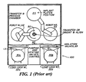
- FIG. 1 shows a prior art wafer handling system.
- the prior art system employs two cassettes holding a plurality of wafers and two load locks.
- a cassette of wafers is loaded into one of the load locks. While one load lock is being vented, the cassette exchanged, and the load lock pumped down, the other load lock remains in a vacuum state and all the wafers from its cassette are processed in sequence. That is, a load lock is cycled to vacuum and back to atmosphere once for each cassette of wafers placed in the load lock.
- processing of wafers occurs by transferring the wafers between robots via a transfer station. That is, robot #1 removes a wafer from a cassette in the load lock #1 and transfers the wafer to the transfer station 50. Robot #2 removes the wafer from the transfer station 50 and places the wafer on the platen 25 for processing at the process station. After the wafer is processed, robot #1 removes the wafer from the platen 25 and returns this wafer to the cassette in load lock #1. This cycle is followed until all the wafers in the cassette are processed.
- This system works well for 200mm wafers that are transported in cassettes where the cassettes maybe introduced into the vacuum system. Since FOUP's cannot be placed into a vacuum system this system requires wafers to be transferred from a FOUP into a wafer holding device in the load lock. To compensate for the additional handling step, the prior art system must employ complex rapid atmospheric wafer handling that places wafers at increased risk of damage.
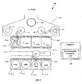
- FIG. 2 illustrates a system 100 suitable for practicing the present invention. Nevertheless, those skilled in the art will understand that this is a diagrammatic representation of a three-dimensional form and that various forms and details can be implemented without departing from the scope of the present invention.
- the system 100 includes one or more docking stations 101a through 101d to receive one or more FOUPs 104a through 104d. Each of the docking stations 101 a through 101d includes a door 102a through 102d that can be opened automatically by commercially available equipment, not shown.
- a robot 110 operating in atmosphere is capable of moving along a track 111 to load and unload wafers from each of the docking stations 101a through 101d.
- the robot 110 is capable of additional degrees of freedom including vertical, radial and azimuthal movements.
- a vacuum chamber 160 is provided with four load locks 120a through 120d, each of which is provided with an atmospheric valve 121a through 121 d, which opens to allow transfer of a wafer in atmosphere from one of the docking stations 101a through 101d to a selected load lock.
- Each of the load locks 120a through 120d include a vacuum valve 122a through 122d, which opens to allow transfer of the wafer from the load lock into the vacuum chamber 160.
- Load locks 120a through 120d are further equipped with venting and pumping means and with other valves and controls (not shown) that one skilled in the art will recognize.
- the load locks 120a through 120d are shown as being located side-by-side but can optionally be disposed as two pairs one above the other.
- a process station 150 addressable by a robot 131 and a robot 132.
- Robot 131 can address a holding station 141, which can pre-orient a wafer for processing at process station 150.
- Robot 132 can address a holding station 142 that is similar to the holding station 141.
- a controller 170 is provided to control sequencing of wafers through the system 100 and to control activation, deactivation and overall coordination of mechanical and environmental operations during wafer handling and processing.
- the environmental operations include, for example, control of vent and pump down operations for each of the load locks 120a through 120d and control of the clean environment in the vacuum chamber 160.
- the mechanical operations include, for example, instructing of each robot or wafer handler and control of certain valves and other mechanical devices.
- the controller 170 can optionally include an environmental controller 172 to control all or part of the environmental operations.
- vacuum processes benefit from the present invention.
- One such vacuum process is ion implantation.
- the implantation process time per wafer is often less than about 10 seconds.
- wafer throughputs of greater than 300 wafers per hour may be achievable for an ion implantation process.
- one wafer is removed from a slot in a selected FOUP or cassette in one of the docking stations 101a through 101d by the robot 110, and placed into one of the load locks 120a through 120d, which is pumped down to vacuum, and opened to the vacuum chamber 160.
- the wafer is transported to one of the holding stations 141, 142 by one of the robots 131 and 132 depending upon which load lock the wafer is placed.
- Which robot and holding station is selected to handle the wafer depends on which load lock the wafer is loaded into at atmosphere. For example, if the wafer is loaded into load lock 120a or 120b at atmosphere, robot 131 and holding station 141 are employed to process the wafer through the vacuum chamber 160.
- robot 132 and holding station 142 are employed to process the wafer through the vacuum chamber 160.
- the holding stations may be alignment stations for alignment and preorientation of wafers.
- all other wafer handling, atmospheric and vacuum, such as, alignment and orientation is performed as a background operation in parallel to the processing of a wafer on the process station 150.
- the processed wafer is placed directly into one of the load locks 120a through 120d, which is vented and opened to atmosphere to allow removal of the processed wafer.
- System 100 advantageously provides single-wafer vacuum entry and exit, and single-wafer processing. That is, one wafer rather than a batch of wafers is at risk at one time, thus providing greater flexibility in the selection and control of process variables such as beam incident angle, and cycle times at the various steps in the process. Further, system throughput does not depend on lot size as is the case when wafers are introduced into the vacuum system in batches of twenty-five. Furthermore, single wafer processing allows for the internal dimensions of each load lock to be minimized so that the internal volume of each load lock is significantly less than a load lock constructed to receive more than one wafer. The result of minimizing the internal volume of each load lock is shorter cycle times for pumping down and venting of each load lock due to the smaller volume to evacuate.
- the process station 150 can include an electrostatic chuck or platen that clamps the wafers using only backside contact.
- the process station 150 optionally includes three lift pins that are actuated by a mechanism below the surface of a platen. In operation, a wafer is extended over the electrostatic chuck by one of the robots 131, 132 and the lift pins are raised. The selected robot is retracted and the pins are lowered. When the electrostatic chuck senses the presence of the wafer, the chuck applies a clamping voltage to ensure secure clamping.
- the electrostatic chuck is tilted as appropriate and moved so as to traverse the wafer through a ribbon-shaped or scanned ion beam to accomplish uniform ion implantation.
- the chuck returns to the start position, unclamps the wafer, the pins are raised, and the robot that loaded the platen with the wafer unloads the wafer from the process station. With the robot under the wafer, the pins are lowered to transfer the wafer onto an arm of one of the robot.
- the following exemplary process flow illustrates the hardware and process steps to achieve this end.
- the total cycle time per wafer through the system 100 is about sixty seconds. Those skilled in the art will recognize that this cycle time is merely illustrative and may be shortened resulting in yet higher throughput, but the use of sixty seconds facilitates the discussion below.
- the vent time and the pumpdown time for each of the load locks 120a through 120d is about sixteen seconds for each operation, and the atmospheric load and unload time by the robot 110 is about ten seconds.
- each of the load locks 120a through 120d can be opened after the end of every process step, several seconds before the next processing step begins. This tends to make the pressure in the system identical during every process step, removing a source of systematic process variation that occurs in other process flows.
- the load locks 120a through 120d are physically arranged in two stacks of two load locks.
- the robot 110 moving on the track 111 in atmosphere can address both stacks and all FOUPs 104a through 104d, or cassettes.
- the robot 110 can include a vacuum chuck, and is capable of relatively high speed movement.
- Each of the robots 131 and 132 operate independently of each other in vacuum.
- the robot 131 accesses a first pair of load locks, one of the handling stations 141,142, and the process station 150.
- the robot 132 accesses a second pair of load locks, the other of the handling stations 141, 142, and the process station 150.
- Those skilled in the art will recognize that is possible to arrange and stack more than two pair of load locks.
- the robot 110 in atmosphere can use a vacuum chuck to securely hold the wafers by the backside, it is permitted to use high accelerations and fast motions.
- a single robot may be sufficient to meet throughput requirements, but more than one robot 110 can be used if desired.
- Figure 2 is referred to below to discuss an exemplary set of wafer transport paths.
- the exemplary set of wafer transport paths focuses on the FOUP 104a holding one or more wafers located at the docking station 101a, the load locks 120a and 120b, the first vacuum robot 131, and the holding station 141.
- a FOUP may hold up to twenty-five wafers in a vertical array and as such, the exemplary set of wafer transport paths are repeated twenty-five times until all wafers in the FOUP have completed processing. Nonetheless, those skilled in the art will recognize that the details discussed below apply equally to an exemplary set of wafer transport paths for the FOUPs 104b through 104d loaded into the docking stations 101b through 101d.
- FIG. 3 discussed below further illustrates the exemplary set of wafer transport paths as applied to the load locks 120a through 120d.
- the exemplary wafer transport paths employ the operation of load locks 120a, 120b, first vacuum robot 131, and first handling station 141.
- the discussion of the exemplary set of wafer transport paths are equally applicable to the operation of load locks 120c and 120d, the second vacuum robot 132, and the handling station 142, because each grouping of wafer handling devices operate in a concurrent manner.
- each FOUP 104a in the docking station 101a can be inserted or removed from each of the docking stations 101b through 101d, to maintain a continuous or near continuous supply of unprocessed wafers.
- Such operations can occur with flexible scheduling in background to the sequence of operations described below.
- Each new load of wafers will in due course be processed by a similar sequence of steps to that described below.
- the next load of wafers can be removed from a selected one of the docking stations 101b, 101c, or 101d, in a similar sequence.
- each wafer removed can be returned to the slot in the cassette or FOUP from which it was removed.
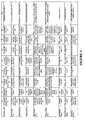
- FIG. 3 illustrates an exemplary timing diagram for the system 100 that illustrates the parallel processing of wafers so that each subsequent wafer lags an immediately preceding wafer by about ninety degrees in cycle phase through the process.
- the load locks 120a through 120d operate in a sequential manner so that at a given point in time one load lock is open to vacuum, one load lock is open to atmosphere, one load lock is venting, and one load lock is pumping down. That is, about every twelve to fifteen seconds, the next load lock in the sequence carries out the same step as its predecessor. The time for each of these steps is not required to be equal, but each load lock goes through this same sequence repetitively, recommencing the full cycle at equally phased intervals. Thus, it follows that every operation in the sequence is repeated about every twelve to fifteen seconds later.
- the actions of the robots 131, 132, the holding stations 141, 142 and the load locks 120a through 120d alternate between right and left, where load locks 120a and 120b, robot 131, and holding station 141 are classified as left in the system 100, and load locks 120c and 120d, robot 132, and holding station 142 are classified as right in the system 100. Furthermore, a wafer introduced into a first load lock on the left side of the system 100 is removed after processing from a second load lock on the left side of the system 100. That is, a wafer loaded into the load lock 120a at atmosphere for processing is unloaded from the load lock 120b at atmosphere when the processing is complete.
- This allotted cycle time of about fifty to sixty seconds helps to maintain the requisite level of cleanliness in each load lock to prevent particulate contamination of a wafer during pump down and venting.
- the fifty second cycle time allots about fifteen seconds for venting, ten seconds for wafer exchange at atmosphere, and about fifteen for pump down with the remaining time used for system pressure equalization.
- the robot 110 collects a wafer from a slot in the FOUP 104a in the docking station 101a and introduces it into the load lock 120a.
- the atmospheric valve 121a closes, and the load lock 120a is roughed down to a pressure of around 1 Pa.
- the vacuum valve 122a opens to a high vacuum (for example 1 x 10 -3 Pa), causing a brief rise in pressure in the vacuum chamber 160 lasting about one to four seconds. It will be seen that the timing of this event is often considered important.
- the robot 131 begins to fetch the wafer from the load lock 120a, and at about time twenty-two (22) seconds the robot 131 places the wafer on the holding station 141.
- the holding station 141 determines the correct orientation of the wafer.
- the robot 131 While the holding station 141 determines the correct orientation of the wafer, at about time twenty-three (23) seconds, the robot 131 begins to remove an already processed wafer from the process station 150, where its processing just completed. The processed wafer is placed in the load lock 120a by the robot 131 since it was loaded as an unprocessed wafer from load lock 120b. At about time twenty-four (24) seconds, the vacuum valve 122d opens. Those skilled in the art will recognize that because of the above timing any pressure burst in the vacuum chamber 160 occurs after the processing of a wafer has completed, and before the processing of the next wafer commences. Further, at about time twenty-four (24) seconds, the robot 132 commences placing another wafer onto the process station 150 from the holding station 142.
- the robot 131 removes the first wafer from the holding station 141 at about time twenty-five (25) seconds, and is ready to place that wafer onto the process station 150.
- the robot 132 begins to remove the processed wafer from the process station 150.
- the vacuum valve 122b opens to introduce a new wafer to the vacuum chamber 160, causing a pressure burst in the vacuum chamber 160.
- the robot 131 commences to move the first wafer from holding station 141 onto the process station 150, following the removal of the processed wafer from the process station 150 by the robot 132.
- Robot 131 after placing the first wafer onto the process station 150, removes the new wafer from the load lock 120b and places the new wafer onto the holding station 141 for orientation.
- processing of the first wafer commences, and stops at about time thirty-eight (38) seconds.
- the robot 131 commences removal of the now processed first wafer from the process station 150.
- the robot 131 places the first wafer into load lock 120b and the vacuum valve 122b closes at about time forty-two (42) seconds. Venting of the load lock 120b occurs from about time forty-two (42) seconds through about time fifty-four (54) seconds.
- the atmospheric valve 121b opens as soon as the pressure equalizes in the load lock 120b.
- the robot 110 in atmosphere picks the initially processed wafer out of the load lock 120b and returns that wafer to the slot in the FOUP 104a from which it came, completing the operation at about time fifty-seven (57) seconds.
- Figure 3 illustrates an exemplary timing diagram for the present invention, beginning at a point in time T0 after a number of wafers from a lot of wafers have cycled through system 100 for wafer processing (i.e., steady state).
- first load lock 120a is at atmosphere for the loading of a wafer 10
- second load lock 120b is at vacuum loading a wafer 6 (which entered the system from load lock 120a) from process station 150
- third load lock 120c is roughing down with wafer 9 for processing
- fourth load lock 120d is venting with a wafer 5 (which entered the system from load lock 120c) that has completed processing.
- robot 131 picks wafer 6 from process station 150 and loads it into load lock 120b for return to atmosphere.
- Robot 132 picks a wafer 7 off of holding station 142 and places wafer 7 onto process station 150 for processing once robot 131 removes wafer 6 therefrom. Wafer 7 was brought to vacuum in load lock 120d. While the load locks and robots perform their respective operations, holding station 141 orients a wafer 8 previously loaded by robot 131 from load lock 120b and holding station 142 is idle waiting for wafer 9 to reach vacuum. The process station 150 is idle for the unloading of wafer 6 and the loading of wafer 7. All even numbered wafers come from load locks 120a and 120b, while odd numbered wafers come from load locks 120c and 120d.
- Load lock 120a begins roughing down with the wafer 10
- load lock 120b vents with wafer 6
- load lock 120c opens at vacuum for the removal of wafer 9
- load lock 120d opens at atmosphere for unloading of wafer 5.
- robot 131 removes wafer 8 from transfer station 141 and idles waiting to place it onto process station 150
- robot 132 picks wafer 9 from load lock 120c, and loads it onto holding station 142.
- Holding station 141 idles while wafer 8 is removed, and holding station 142 idles to receive wafer 9.
- Process station 150 processes wafer 7.
- Load lock 120a opens at vacuum for the removal of wafer 10
- load lock 120b opens at atmosphere for removal of wafer 6
- load lock 120c is open at vacuum awaiting the loading of wafer 7 from process station 150
- load lock 120d is open at atmosphere for the loading of wafer 11.
- robot 131 places wafer 8 onto process station 150.
- robot 132 removes wafer 7 from process station 150 and loads wafer 7 into load lock 120c for return to atmosphere.
- Holding station 141 remains idle awaiting the next wafer and holding station 142 orients wafer 9.
- Process station 150 idles to remove wafer 7 and receive wafer 8.
- First load lock 120a is open to vacuum and robot 131 is unloading wafer 10
- load lock 120b is open to atmosphere for the loading of a wafer 12.
- Load lock 120c is venting with wafer 7, and load lock 120d is roughing down with wafer 11.
- robot 131 picks wafer 10 from load lock 120a and places it onto holding station 141, while robot 132 removes wafer 9 from holding station 142, and idles waiting for the processing of wafer 8 to complete.
- Holding station 141 idles to receive wafer 10 from robot 131 and holding station 142 idles for the removal just oriented wafer 9.
- Process station 150 processes wafer 8.
- First load lock 120a receives wafer 8 at vacuum from process station 150 via robot 131, second load lock 120b roughs down with wafer 12, load lock 120c opens at atmosphere for the unloading of wafer 7, and fourth load lock 120d opens at vacuum for the unloading of wafer 11.
- Robot 131 picks wafer 8 from process station 150, and loads first load lock 120a with wafer 8.
- Robot 132 places wafer 9 onto process station 150 for processing. While robots 131 and 132 handle wafers, holding station 141 orients wafer 10 and handling station 142 idles for the removal of wafer 9.
- Process station 150 idles for the unloading of wafer 8 by robot 131 and the loading of wafer 9 by robot 132.
- Load lock 120a vents with wafer 8
- load lock 120b opens at vacuum for the removal of wafer 12
- load lock 120c is open at atmosphere for the loading of wafer 13
- load lock 120d is open at vacuum unloading wafer 11.
- robot 131 unloads the wafer 10 from holding station 141 and waits for process station 150 to process wafer 9.
- Robot 132 picks wafer 11 from load lock 120d and places it onto holding station 142 for orientation. Holding station 141 idles for the removal of wafer 10 and holding station 142 idles to receive wafer 11.
- Process station 150 processes wafer 9.
- first load lock 120a opens at atmosphere for unloading for wafer 8
- load lock 120b remains open at vacuum awaiting the unloading of wafer 12
- load lock 120c is roughing down with wafer 13
- load lock 120d is open at vacuum for the loading of wafer 9 from process station 150.
- second robot 132 picks wafer 9 from process station 150, and loads it into load lock 120d.
- Robot 131 loads wafer 10 onto process station 150 after robot 132 removes wafer 9 therefrom.
- Holding station 141 idles awaiting the loading of wafer 12 and holding station 142 orients wafer 11.
- Process station 150 idles for the removal of wafer 9 and the placement of wafer 10.
- system 100 carries out the following steps.
- Load lock 120a is open at atmosphere for the loading of wafer 14
- load lock 120b is at vacuum unloading wafer 12
- load lock 120c opens at vacuum with wafer 13
- load lock 120d vents with wafer 9.
- Robot 131 picks wafer 12 from load lock 120b and loads it onto holding station 141.
- Robot 132 unloads wafer 11 from holding station 142, and idles awaiting the completion of processing of wafer 10 on process station 150.
- Holding station 141 idles to receive wafer 12 and holding station 142 idles for the removal of wafer 11.
- Process station 150 processes wafer 10.
- System 100 at time T8, carries out the following steps.
- Load lock 120a containing wafer 14, roughs down.
- Load lock 120b is open at vacuum for the loading of wafer 10 from process station 150
- load lock 120c is open at vacuum for the removal of wafer 13
- load lock 120d opens at atmosphere for the unloading of wafer 9.
- Robot 131 picks wafer 10 from process station 150 and loads it into load lock 120b for venting to atmosphere.
- Robot 132 loads wafer 11 onto process station 150 once wafer 10 is removed therefrom.
- Holding station 141 orients wafer 12 while holding station 142 idles awaiting the loading of wafer 13 from load lock 120c.
- Process station 150 idles for the removal of wafer 10 and the placement of wafer 11.
- System 100 continues in the above-detailed sequence of steps or operations until each wafer in the lot of wafers loaded into a selected docking station has been processed by and through the system. Nevertheless, those skilled in the art will recognize that system 100 can perform the above-described steps and operations in a continuous or near-continuous manner so long as an adequate supply of wafers for processing is provided to the system. That is, a number of docking stations, such as four, can be associated with the system to hold subsequent lots of unprocessed wafers for processing by the system. Moreover, the above discussion details that advantageous pairing of load locks to provide a load lock that is empty and open at vacuum awaiting the receipt of a processed wafer. The ability to provide a load lock open at vacuum waiting to receive a processed wafer as soon as processing is complete allows system 100 to realize a beneficial reduction in wafer processing cycle time.
- robots 131 and 132 might be placed one above the other, or even integrated onto a common center to act as a robot with two concentric independent articulating arms.
- load locks 120a through 120d need not be disposed in a straight line, but could be stacked two upon two.
- holding stations 141 and 142 need not be as shown, but could be located in any suitable position, including integrating them within each of robots 131 and 132.
Landscapes
- Engineering & Computer Science (AREA)
- Physics & Mathematics (AREA)
- Condensed Matter Physics & Semiconductors (AREA)
- General Physics & Mathematics (AREA)
- Manufacturing & Machinery (AREA)
- Computer Hardware Design (AREA)
- Microelectronics & Electronic Packaging (AREA)
- Power Engineering (AREA)
- Container, Conveyance, Adherence, Positioning, Of Wafer (AREA)
- Mechanical Treatment Of Semiconductor (AREA)
Claims (31)
- Un procédé de traitement de tranches, le procédé comprenant les opérations suivantes :fournir une première paire (120a, 120b) de sas de chargement et une deuxième paire (120c, 120d) de sas de chargement, chacun des sas de chargement (120a, 120b, 120c, 120d) possédant une première portion s'ouvrant à l'air libre et une deuxième portion s'ouvrant vers le vide dans une chambre à vide (160), ladite chambre à vide (160) comprenant un premier robot à vide (131) et un deuxième robot à vide (132) destinés à manipuler les tranches dans le vide ;commander la première (120a, 120b) et la deuxième (120c, 120d) paires de sas de chargement selon une séquence souhaitée pour faire passer les tranches de l'air libre au vide et retour à l'air libre ;amener le premier robot à vide (131) dans la chambre à vide (160) à retirer une première tranche d'un premier sas de chargement (120a) de la première paire (120a, 120b) de sas de chargement, à transporter ladite première tranche vers une station de traitement (150) pour traitement de la tranche dans la chambre à vide (160) et à charger la première tranche dans un deuxième sas de chargement (120b) de la première paire (120a, 120b) lorsque le traitement de la première tranche est terminé ; etamener le deuxième robot à vide (132) dans la chambre à vide (160) à retirer une deuxième tranche d'un premier sas de chargement (120c) de la deuxième paire (120c, 120d) de sas de chargement, à transporter ladite deuxième tranche vers une station de traitement (150) pour traitement de la tranche dans la chambre à vide (160) et à charger la deuxième des tranches dans un deuxième sas de chargement (120d) de la deuxième paire (120c, 120d) de sas de chargement lorsque le traitement de la deuxième tranche dans la chambre à vide (160) est terminé, où lesdits premier (131) et deuxième (132) robots à vide sont commandés de façon à réduire le temps entre le traitement de tranches successives.
- Un procédé selon la Revendication 1 comprenant en outre l'opération consistant à amener un premier robot atmosphérique (110) à l'air libre à charger et décharger chacune des tranches de la première (120a, 120b) et de la deuxième (120c, 120d) paires de sas de chargement et à transporter chacune de ces tranches entre le premier (120a) et le deuxième (120b) sas de chargement et une station d'accueil (101a, 101b, 101c, 101d) à l'air libre.
- Un procédé selon la Revendication 2 comprenant en outre l'opération consistant à amener le premier robot atmosphérique (110) à répartir les tranches de la station d'accueil (101a, 101b, 101c, 101d) à l'air libre entre le premier (120a) et le deuxième (120b) sas de chargement constituant la première paire (120a, 120b) de sas de chargement et le premier (120c) et le deuxième (120d) sas de chargement formant la deuxième paire (120c, 120d) de sas de chargement d'une manière substantiellement égale afin de fournir un flux substantiellement continu de tranches à la chambre à vide (160).
- Un procédé selon la Revendication 1, où l'opération de commande de la première paire (120a, 120b) de sas de chargement comprend les opérations suivantes :fermer une soupape atmosphérique associée au premier sas de chargement (120a) de la première paire (120a, 120b) de sas de chargement pour aspirer l'air du premier sas de chargement (120a) ; etouvrir une soupape de dépression associée au premier sas de chargement (120a) de la première paire (120a, 120b) de sas de chargement pour amener le premier sas de chargement (120a) à un état de vide.
- Un procédé selon la Revendication 2, où l'opération consistant à amener le premier robot à vide (131) à retirer une première tranche comprend les opérations suivantes :placer la première tranche sur une première station de maintien (141) après retrait de la première tranche du premier (120a) des sas de chargement formant la première paire (120a, 120b) des sas de chargement ; retirer une troisième tranche de la station de traitement (150) située dans la chambre à vide (160) ; etcharger la troisième tranche dans le premier sas de chargement (120a) de la première paire de sas de chargement (120a, 120b).
- Un procédé selon la Revendication 5, où l'opération consistant à amener le premier robot à vide (131) à retirer une première tranche comprend en outre les opérations suivantes :retirer la première tranche de la première station de maintien (141) ; etcharger la première tranche sur la station de traitement (150) pour ledit traitement.
- Un procédé selon la Revendication 6, où les opérations consistant à amener le premier robot à vide (131) et le deuxième robot à vide (132) à retirer des tranches comprennent les opérations suivantes :demander au premier robot à vide (131) de retirer la première tranche du premier sas de chargement (120a) de la première paire (120a, 120b) de sas de chargement et de placer la première tranche sur la première station de maintien (141) dans la chambre à vide (160) ;demander au premier robot à vide (131) de retirer une troisième tranche de la station de traitement (150) dans la chambre à vide (160) et de placer la troisième tranche dans le premier sas de chargement (120a) de la première paire (120a, 120b) de sas de chargement ;demander au deuxième robot à vide (132) de retirer une deuxième tranche d'une deuxième station de maintien (142) dans la chambre à vide (160) et de placer la deuxième tranche sur la station de traitement (150) dans la chambre à vide (160) pour ledit traitement ; età l'issue du traitement de la deuxième tranche sur la station de traitement (150), demander au deuxième robot à vide (132) de retirer la deuxième tranche de la station de traitement (150) dans la chambre à vide (160) et de charger la deuxième tranche dans le deuxième sas de chargement (120d) de la deuxième paire (120c, 120d) de sas de chargement, et demander au premier robot à vide (131) de retirer la première tranche de la première station de maintien (141) et de la placer sur la station de traitement (150) dans la chambre à vide (160) pourtraitement.
- Un procédé selon la Revendication 7, où au moins une (141, 142) des stations de maintien comprend un dispositif d'orientation de tranches capable d'orienter les tranches dans une direction souhaitée.
- Un procédé selon la Revendication 7, où au moins une (141, 142) des stations de maintien comprend un dispositif d'alignement de tranches capable d'aligner les tranches selon un alignement souhaité.
- Un procédé selon la Revendication 2, où ladite station d'accueil (101a, 101b, 101c, 101d) est adaptée de façon à être équipée d'un chariot pour lesdites tranches comprenant une nacelle unifiée à ouverture frontale (FOUP) (104a).
- Un procédé selon la Revendication 1, où chacun des sas de chargement (120a, 120b, 120c, 120d) est capable de contenir une seule tranche seulement.
- Un procédé selon la Revendication 1, où lesdits premier (131) et deuxième (132) robots à vide fonctionnent de manière indépendante, et au moyen desquels une première tranche dans ledit un des sas de chargement (120a, 120b) dans ledit premier sas de chargement (120a, 120b) est soumise aux opérations suivantes :retirer ladite première tranche d'un premier sas de chargement (120a) de ladite première paire (120a, 120b) de sas de chargement avec ledit premier robot à vide (131) pendant que ledit sas de chargement (120a) est ouvert au vide ;utiliser ledit premier robot à vide (131) pour placer ladite première tranche sur une première station de maintien (141) pour orienter ladite première tranche en vue du traitement ;utiliser ledit premier robot à vide (131) pour retirer ladite première tranche de ladite première station de maintien (141) et placer ladite première tranche sur une station de traitement (150) où ladite première tranche est traitée ;utiliser ledit premier robot à vide (131) pour retirer ladite première tranche traitée de ladite station de traitement (150) et placer ladite première tranche dans ledit deuxième sas de chargement (120b) de ladite première paire (120a, 120b) de sas de chargement pendant que ledit deuxième sas de chargement (120b) est ouvert au vide ;mettre ledit deuxième sas de chargement (120b) contenant ladite première tranche à l'air libre ;ouvrir ledit deuxième sas de chargement (120b) et retirer ladite première tranche à l'air libre ;placer une troisième tranche dans ledit deuxième sas de chargement (120b) à l'air libre ;réduire la pression dans ledit deuxième sas de chargement de façon qu'elle corresponde à la pression dans ladite chambre à vide (160) de façon que ledit deuxième sas de chargement (120b) puisse être ouvert dans le vide ; etretirer ladite troisième tranche dudit deuxième sas de chargement (120b), lançant ainsi le cycle de traitement de ladite troisième tranche ;et au moyen desquels ledit deuxième robot à vide (132) effectue les mêmes opérations que le premier robot à vide (131) avec une deuxième tranche à la différence près que ladite deuxième tranche se trouve au départ dans ledit un des sas de chargement (120c, 120d) de la deuxième paire (120c, 120d) de sas de chargement, ledit deuxième robot à vide (132) place ladite deuxième tranche sur une deuxième station de maintien (142), et après traitement, ladite deuxième tranche est placée par ledit deuxième robot à vide (132) dans l'autre sas de chargement (102c, 120d) de ladite deuxième paire (120c, 120d) de sas de chargement et non dans le sas de chargement (120a, 120b) à partir duquel elle est entrée au départ dans la chambre à vide (160).
- Un procédé selon la Revendication 12, comprenant en outre les opérations suivantes :décharger la première tranche d'une nacelle unifiée à ouverture frontale (FOUP) (104a) montée sur une station d'accueil (101a, 101b, 101c, 101d) à l'air libre ; etcharger la première tranche dans ledit premier sas de chargement (120a) pendant que ledit sas de chargement (120a) est ouvert à l'air libre.
- Un procédé selon la Revendication 13, comprenant en outre les opérations suivantes :aspirer ledit premier sas de chargement (120a) avec la première tranche à l'intérieur de celui-ci pour amener la première tranche dans un état de vide ; etouvrir la deuxième portion dudit premier sas de chargement (120a) pour traitement de la première tranche, où les opérations d'aspiration et d'ouverture de la deuxième portion se déroulent dans un ordre cyclique sur chacun des sas de chargement (120a, 120b, 120c, 120d).
- Un procédé selon la Revendication 1 comprenant les opérations suivantes :a) fournir une première (141) et une deuxième (142) stations de transfert pour prétraiter les tranches, ledit premier (131) et ledit deuxième (132) robots à vide fonctionnant de manière indépendante, et le premier robot à vide (131) manipulant des tranches provenant du premier (120a) et du deuxième (120b) sas de chargement formant ladite première paire (120a, 120b) de sas de chargement et le deuxième robot à vide (132) manipulant des tranches provenant du troisième (120c) et du quatrième (120d) sas de chargement formant la deuxième paire (120c, 120d) de sas de chargement ;b) prévider le premier sas de chargement (120a) avec une première tranche à l'intérieur de ce dernier pour lancer un cycle de traitement de la première des tranches ;c) retirer ladite première tranche du premier sas de chargement (120a) en état de vide en utilisant le premier robot à vide (131) et placer ladite première tranche sur ladite première station de transfert (141) pour prétraitement ;d) charger le premier sas de chargement (120a) avec une deuxième tranche provenant de la station de traitement (150) en utilisant le premier robot à vide (131) et mettre le premier sas de chargement (120a) à l'air libre pour terminer un cycle de traitement pour la deuxième tranche ;e) prévider le deuxième sas de chargement (120b) avec une troisième tranche à l'intérieur de ce dernier pour lancer un cycle de traitement de la troisième tranche ;f) retirer la première tranche de la première station de transfert (141) en utilisant le premier robot à vide (131) et placer la première tranche sur la station de traitement (150) pour traitement ;g) retirer la troisième tranche du deuxième sas de chargement en état de vide en utilisant le premier robot à vide (131) et placer la troisième tranche sur ladite première station de transfert (141) pour prétraitement ;h) retirer la première tranche de la station de traitement (150) en utilisant le premier robot à vide (131) et charger le deuxième sas de chargement (120b) ouvert en état de vide avec la première tranche pour mettre à l'air libre afin de terminer le cycle de traitement de la première tranche ;i) retirer la deuxième tranche de la première station de transfert (141) en utilisant le premier robot à vide (131) et placer la deuxième tranche sur la station de traitement (150) pour traitement ; etj) effectuer les opération b à i en utilisant les troisième et quatrième sas de chargement (120c, 120d), le deuxième robot à vide (132), la deuxième station de transfert (142), et la station de traitement (150) pour traiter simultanément les tranches, ladite station de traitement (150) traitant alternativement des tranches fournies par le premier robot à vide (131) et le deuxième robot à vide (132).
- Un procédé selon la Revendication 15 comprenant en outre l'opération consistant à charger chacun des sas de chargement (120a, 120b, 120c, 120d) à l'air libre avec les tranches en utilisant un robot atmosphérique (110).
- Un procédé selon la Revendication 16 comprenant en outre l'opération consistant à demander au robot atmosphérique (110) de répartir les tranches provenant d'une station d'accueil sélectionnée (101a, 101b, 101d, 101d) entre les quatre sas de chargement (120a, 120b, 120c, 120d) d'une manière substantiellement égale afin de fournir un flux substantiellement continu de tranches à la chambre à vide (160).
- Un procédé selon la Revendication 17 comprenant en outre l'opération consistant à charger la station d'accueil sélectionnée (101a, 101b, 101c, 101d) avec une nacelle unifiée à ouverture frontale (FOUP) (104a, 104b, 104c, 104d) maintenant les tranches à traiter.
- Un système destiné à traiter des pièces de fabrication sur une station de traitement dans le vide, ledit système comprenant :une chambre à vide (160) maintenue dans un état de vide poussé et contenant la station de traitement (150) pour traiter les pièces de fabrication, une première station de transfert (141) pour maintenir une première des pièces de fabrication jusqu'à ce que la station de traitement (150) se trouve dans un état prêt, une deuxième station de transfert (142) pour maintenir une deuxième des pièces de fabrication jusqu'à ce que la station de traitement (150) se trouve dans un état prêt, un premier robot à vide (131) pour manipuler la première des pièces de fabrication dans la chambre à vide (160) et un deuxième robot à vide (132) pour manipuler la deuxième des pièces de fabrication dans la chambre à vide (160) ; et au moins quatre sas de chargement (120a, 120b, 120c, 120d) possédant chacun une première portion en interface avec la chambre à vide (160) pour introduire les pièces de fabrication dans la chambre à vide (160) pour traitement sur la station de traitement (150) ; où lesdits premier (131) et deuxième (132) robots à vide agissent de manière indépendante et où chacun transporte les pièces de fabrication d'un sas de chargement (120a, 120b, 120c, 120d) vers une station de transfert (141, 142) puis vers la station de traitement (150) et retour vers un sas de chargement (120a, 120b, 120c, 120d) différent et un moyen de commande pour commander chacun des premier (131) et deuxième (132) robots à vide pour manipuler en continu et successivement les pièces de fabrication introduites à partir de chacun des sas de chargement (120a, 120b, 120c, 120d), le premier robot à vide (131) envoyant en séquence une première des tranches d'un premier (120a) des sas de chargement (120a, 120b) vers la station de traitement (150) via la première station de transfert (141) et à l'issue du traitement vers un deuxième (120b) des sas de chargement (120a, 120b) pour retour vers un chariot à l'air libre, le deuxième robot à vide (132) envoyant en séquence une deuxième des tranches d'un troisième (120c) des sas de chargement (120c, 120d) vers la station de traitement (150) via la deuxième station de transfert (142) et à l'issue du traitement vers un quatrième (120d) des sas de chargement (120c, 120d) pourretour vers le chariot à l'air libre.
- Un système selon la Revendication 19, comprenant en outre :une station d'accueil (101a, 101b, 101c, 101d) à l'air libre destinée à recevoir et à maintenir un chariot pour les pièces de fabrication ; etun robot atmosphérique (110) fonctionnant à la pression atmosphérique pour transporter les pièces de fabrication entre le chariot relié à la station d'accueil (101a, 101b, 101c, 101d) et chacun des sas de la pluralité de sas de chargement (120a, 120b, 120c, 120d).
- Un système selon la Revendication 19, comprenant en outre un moyen de commande du vide destiné à maintenir un vide poussé dans la chambre à vide (160) contenant la station de traitement (150).
- Un système selon la Revendication 20, comprenant en outre un système de régulation climatique destiné à pomper et à tirer l'air de chacun des sas de chargement (120a, 120b, 120c, 120d).
- Un système selon la Revendication 22, où ledit moyen de commande commande en outre ledit système de régulation climatique et une ou plusieurs soupapes associées à chacun des sas de chargement (120a, 120b, 120c, 120d) pour pomper et tirer l'air de chacun desdits sas de chargement (120a, 120b, 120c, 120d) selon une séquence prédéterminée.
- Un système selon la Revendication 19, où au moins une des stations de transfert (141, 142) comprend un moyen de détecter et de corriger une orientation des pièces de fabrication.
- Un système selon la Revendication 19, où au moins une des stations de transfert (141, 142) comprend un moyen de détecter et de corriger un alignement des pièces de fabrication.
- Un système selon la Revendication 19, où la station de traitement (150) comprend un mandrin électrostatique destiné à maintenir la pièce de fabrication pendant le traitement.
- Un système selon la Revendication 22, où le moyen de commande commande
un mouvement séquentiel de la pièce de fabrication qui va du chariot de la station d'accueil (101a, 101b, 101c, 101d) à la pression atmosphérique au chargement de la pièce de fabrication dans le premier (120a) des sas de chargement (120a, 120b, 120c, 120d) par le robot atmosphérique (110),
la réception de la pièce de fabrication dans la chambre à vide (150) par le premier robot à vide (131),
le traitement de la pièce de fabrication dans la station de traitement (160),
le chargement de la pièce de fabrication à l'issue du traitement dans le deuxième (120b) des sas de chargement (120a, 120b, 120c, 120d) par le premier robot à vide (131), et
le chargement de la pièce de fabrication dans le chariot provenant du deuxième (120b) des sas de chargement (120a, 120b, 120c, 120d) par le robot atmosphérique (110). - Un système selon la Revendication 22, où le chariot comprend une nacelle unifiée à ouverture frontale (FOUP) (104a, 104b, 104c, 104d).
- Un système selon la Revendication 28, où le moyen de commande commande le mouvement séquentiel des pièces de fabrication y compris l'orientation des pièces de fabrication pendant une période où les pièces de fabrication se trouvent dans la première (141) et la deuxième (142) stations de transfert.
- Un système selon la Revendication 19, où chacun des sas de chargement (120a, 120b, 120c, 120d) est dimensionné de façon à contenir une seule pièce de fabrication seulement.
- Un système selon la Revendication 22, où le chariot comprend une cassette.
Applications Claiming Priority (3)
| Application Number | Priority Date | Filing Date | Title |
|---|---|---|---|
| US33425101P | 2001-11-29 | 2001-11-29 | |
| US334251P | 2001-11-29 | ||
| PCT/US2002/038228 WO2003046958A2 (fr) | 2001-11-29 | 2002-11-27 | Procede et appareil de manipulation de tranche |
Publications (2)
| Publication Number | Publication Date |
|---|---|
| EP1454340A2 EP1454340A2 (fr) | 2004-09-08 |
| EP1454340B1 true EP1454340B1 (fr) | 2006-09-13 |
Family
ID=23306329
Family Applications (1)
| Application Number | Title | Priority Date | Filing Date |
|---|---|---|---|
| EP02791341A Expired - Lifetime EP1454340B1 (fr) | 2001-11-29 | 2002-11-27 | Procédé et appareil de manipulation de plaquette |
Country Status (7)
| Country | Link |
|---|---|
| US (1) | US7059817B2 (fr) |
| EP (1) | EP1454340B1 (fr) |
| JP (1) | JP4327599B2 (fr) |
| AT (1) | ATE339773T1 (fr) |
| AU (1) | AU2002365591A1 (fr) |
| DE (1) | DE60214763T2 (fr) |
| WO (1) | WO2003046958A2 (fr) |
Families Citing this family (29)
| Publication number | Priority date | Publication date | Assignee | Title |
|---|---|---|---|---|
| US6729824B2 (en) * | 2001-12-14 | 2004-05-04 | Applied Materials, Inc. | Dual robot processing system |
| JP3865703B2 (ja) * | 2002-10-25 | 2007-01-10 | ファナック株式会社 | 物品搬送システム及び搬送方法 |
| JP3674864B2 (ja) * | 2003-03-25 | 2005-07-27 | 忠素 玉井 | 真空処理装置 |
| US7112808B2 (en) * | 2004-02-25 | 2006-09-26 | Axcelis Technologies, Inc. | Wafer 2D scan mechanism |
| WO2005097640A2 (fr) * | 2004-04-05 | 2005-10-20 | Axcelis Technologies, Inc. | Procede de transport alterne d'une piece a travailler a travers un faisceau ionique |
| KR20060128001A (ko) * | 2004-04-09 | 2006-12-13 | 액셀리스 테크놀로지스, 인크. | 스프링 및 평형추를 이용한 왕복 회전 운동에 의한 웨이퍼주사 시스템 |
| US7119343B2 (en) * | 2004-05-06 | 2006-10-10 | Axcelis Technologies, Inc. | Mechanical oscillator for wafer scan with spot beam |
| US7477956B2 (en) * | 2004-07-12 | 2009-01-13 | Applied Materials, Inc. | Methods and apparatus for enhancing electronic device manufacturing throughput |
| US20060097196A1 (en) * | 2004-11-08 | 2006-05-11 | Axcelis Technologies Inc. | Dose uniformity during scanned ion implantation |
| JP4907077B2 (ja) * | 2004-11-30 | 2012-03-28 | 株式会社Sen | ウエハ処理装置及びウエハ処理方法並びにイオン注入装置 |
| KR100621775B1 (ko) * | 2005-04-15 | 2006-09-15 | 삼성전자주식회사 | 기판 세정장치 |
| US7694583B2 (en) * | 2005-05-05 | 2010-04-13 | Control Gaging, Inc. | Gripper gage assembly |
| JP4767641B2 (ja) * | 2005-09-27 | 2011-09-07 | 大日本スクリーン製造株式会社 | 基板処理装置および基板搬送方法 |
| JP4098338B2 (ja) | 2006-07-20 | 2008-06-11 | 川崎重工業株式会社 | ウェハ移載装置および基板移載装置 |
| US8153513B2 (en) * | 2006-07-25 | 2012-04-10 | Silicon Genesis Corporation | Method and system for continuous large-area scanning implantation process |
| US20080075563A1 (en) * | 2006-09-27 | 2008-03-27 | Mclane James R | Substrate handling system and method |
| US20080138178A1 (en) * | 2006-12-06 | 2008-06-12 | Axcelis Technologies,Inc. | High throughput serial wafer handling end station |
| US7949425B2 (en) * | 2006-12-06 | 2011-05-24 | Axcelis Technologies, Inc. | High throughput wafer notch aligner |
| US8500382B2 (en) * | 2007-05-22 | 2013-08-06 | Axcelis Technologies Inc. | Airflow management for particle abatement in semiconductor manufacturing equipment |
| US7772571B2 (en) * | 2007-10-08 | 2010-08-10 | Advanced Ion Beam Technology, Inc. | Implant beam utilization in an ion implanter |
| US7987014B2 (en) * | 2008-05-15 | 2011-07-26 | Texas Instruments Incorporated | Systems and methods for selecting wafer processing order for cyclical two pattern defect detection |
| JP6208419B2 (ja) * | 2012-09-19 | 2017-10-04 | 株式会社ダイヘン | 算出装置、搬送ロボットシステム、及び算出方法 |
| US9663854B2 (en) * | 2013-03-14 | 2017-05-30 | Taiwan Semiconductor Manufacturing Company, Ltd. | High-throughput system and method for post-implantation single wafer warm-up |
| US10157763B2 (en) * | 2013-08-29 | 2018-12-18 | Varian Semiconductor Equipment Associates, Inc. | High throughput substrate handling endstation and sequence |
| US9378992B2 (en) | 2014-06-27 | 2016-06-28 | Axcelis Technologies, Inc. | High throughput heated ion implantation system and method |
| US9607803B2 (en) | 2015-08-04 | 2017-03-28 | Axcelis Technologies, Inc. | High throughput cooled ion implantation system and method |
| US10790177B2 (en) * | 2017-11-14 | 2020-09-29 | Taiwan Semiconductor Manufacturing Co., Ltd. | Systems, devices, and methods for using a real time environment sensor in a FOUP |
| CN109244186B (zh) * | 2018-09-19 | 2024-02-27 | 通威太阳能(安徽)有限公司 | 一种新型背钝化背膜正膜机台镀膜连体上下料装置及方法 |
| US11335578B2 (en) * | 2020-02-13 | 2022-05-17 | Kawasaki Jukogyo Kabushiki Kaisha | Substrate transfer apparatus and method of measuring positional deviation of substrate |
Family Cites Families (20)
| Publication number | Priority date | Publication date | Assignee | Title |
|---|---|---|---|---|
| US5019233A (en) * | 1988-10-31 | 1991-05-28 | Eaton Corporation | Sputtering system |
| JPH05275511A (ja) * | 1991-03-01 | 1993-10-22 | Tokyo Electron Ltd | 被処理体の移載システム及び処理装置 |
| US5482607A (en) * | 1992-09-21 | 1996-01-09 | Nissin Electric Co., Ltd. | Film forming apparatus |
| US5544421A (en) * | 1994-04-28 | 1996-08-13 | Semitool, Inc. | Semiconductor wafer processing system |
| US5486080A (en) * | 1994-06-30 | 1996-01-23 | Diamond Semiconductor Group, Inc. | High speed movement of workpieces in vacuum processing |
| TW295677B (fr) * | 1994-08-19 | 1997-01-11 | Tokyo Electron Co Ltd | |
| JPH0936198A (ja) * | 1995-07-19 | 1997-02-07 | Hitachi Ltd | 真空処理装置およびそれを用いた半導体製造ライン |
| GB2316224B (en) | 1996-06-14 | 2000-10-04 | Applied Materials Inc | Ion implantation method |
| US6034000A (en) | 1997-07-28 | 2000-03-07 | Applied Materials, Inc. | Multiple loadlock system |
| GB2382717B (en) | 1998-07-21 | 2003-09-03 | Applied Materials Inc | Ion Implantation Beam Monitor |
| US6616394B1 (en) * | 1998-12-30 | 2003-09-09 | Silicon Valley Group | Apparatus for processing wafers |
| GB2349269A (en) | 1999-04-19 | 2000-10-25 | Applied Materials Inc | Ion implanter |
| US6350097B1 (en) | 1999-04-19 | 2002-02-26 | Applied Materials, Inc. | Method and apparatus for processing wafers |
| GB2349204B (en) | 1999-04-19 | 2004-03-03 | Applied Materials Inc | A method of detecting the position of a wafer |
| US6428262B1 (en) * | 1999-08-11 | 2002-08-06 | Proteros, Llc | Compact load lock system for ion beam processing of foups |
| GB2355337B (en) | 1999-10-12 | 2004-04-14 | Applied Materials Inc | Ion implanter and beam stop therefor |
| US6577923B1 (en) * | 1999-12-23 | 2003-06-10 | Applied Materials, Inc. | Apparatus and method for robotic alignment of substrates |
| US6520727B1 (en) * | 2000-04-12 | 2003-02-18 | Asyt Technologies, Inc. | Modular sorter |
| JP4021125B2 (ja) * | 2000-06-02 | 2007-12-12 | 東京エレクトロン株式会社 | ウェハ移載装置の装置ユニット接続時に用いられるレールの真直性保持装置 |
| US6748293B1 (en) * | 2003-03-24 | 2004-06-08 | Varian Semiconductor Equipment Associates, Inc. | Methods and apparatus for high speed object handling |
-
2002
- 2002-11-27 US US10/307,022 patent/US7059817B2/en not_active Expired - Fee Related
- 2002-11-27 AT AT02791341T patent/ATE339773T1/de not_active IP Right Cessation
- 2002-11-27 EP EP02791341A patent/EP1454340B1/fr not_active Expired - Lifetime
- 2002-11-27 AU AU2002365591A patent/AU2002365591A1/en not_active Abandoned
- 2002-11-27 DE DE60214763T patent/DE60214763T2/de not_active Expired - Lifetime
- 2002-11-27 WO PCT/US2002/038228 patent/WO2003046958A2/fr active IP Right Grant
- 2002-11-27 JP JP2003548285A patent/JP4327599B2/ja not_active Expired - Fee Related
Also Published As
| Publication number | Publication date |
|---|---|
| US7059817B2 (en) | 2006-06-13 |
| AU2002365591A1 (en) | 2003-06-10 |
| DE60214763D1 (de) | 2006-10-26 |
| US20030123958A1 (en) | 2003-07-03 |
| ATE339773T1 (de) | 2006-10-15 |
| WO2003046958A3 (fr) | 2003-12-31 |
| WO2003046958A2 (fr) | 2003-06-05 |
| JP4327599B2 (ja) | 2009-09-09 |
| EP1454340A2 (fr) | 2004-09-08 |
| DE60214763T2 (de) | 2007-09-06 |
| JP2005510870A (ja) | 2005-04-21 |
Similar Documents
| Publication | Publication Date | Title |
|---|---|---|
| EP1454340B1 (fr) | Procédé et appareil de manipulation de plaquette | |
| EP0690480B1 (fr) | Mouvement de pièces à haute vitesse pour traitement sous vide | |
| KR102656329B1 (ko) | 최적화된 저 에너지/고 생산성 디포지션 시스템 | |
| US9305818B2 (en) | Substrate processing apparatus | |
| EP1079418B1 (fr) | Dispositif de traitement sous vide et sa méthode d'opération | |
| KR100847888B1 (ko) | 반도체 소자 제조 장치 | |
| US6176667B1 (en) | Multideck wafer processing system | |
| JP5323718B2 (ja) | 高生産性ウエハ連続処理末端装置 | |
| KR101196914B1 (ko) | 로드록 및 버퍼를 갖는 워크피스 처리 시스템 | |
| US8292563B2 (en) | Nonproductive wafer buffer module for substrate processing apparatus | |
| JP2011049585A (ja) | 基板搬送装置及び方法 | |
| JPH04190840A (ja) | 真空処理装置 | |
| KR101106803B1 (ko) | 반도체 웨이퍼 처리용 반도체 제조 시스템, 대기중 로봇핸들링 장비 및 반도체 웨이퍼의 반송 방법 | |
| US11600503B2 (en) | High-throughput, multi-chamber substrate processing system | |
| WO2008039702A2 (fr) | Système et procédé de traitement de substrats | |
| KR101105924B1 (ko) | 웨이퍼 핸들링 방법 및 시스템 | |
| KR101039441B1 (ko) | 웨이퍼 센터링 방법 | |
| US7019315B2 (en) | System and method for serial ion implanting productivity enhancements | |
| USRE39824E1 (en) | Vacuum processing apparatus and operating method with wafers, substrates and/or semiconductors | |
| KR101929872B1 (ko) | 기판 처리 장치 및 기판 처리 방법 |
Legal Events
| Date | Code | Title | Description |
|---|---|---|---|
| PUAI | Public reference made under article 153(3) epc to a published international application that has entered the european phase |
Free format text: ORIGINAL CODE: 0009012 |
|
| 17P | Request for examination filed |
Effective date: 20040630 |
|
| AK | Designated contracting states |
Kind code of ref document: A2 Designated state(s): AT BE BG CH CY CZ DE DK EE ES FI FR GB GR IE IT LI LU MC NL PT SE SK TR |
|
| AX | Request for extension of the european patent |
Extension state: AL LT LV MK RO SI |
|
| RIN1 | Information on inventor provided before grant (corrected) |
Inventor name: SIERADZKI, MANNY Inventor name: WHITE, NICHOLAS, R. |
|
| GRAP | Despatch of communication of intention to grant a patent |
Free format text: ORIGINAL CODE: EPIDOSNIGR1 |
|
| GRAS | Grant fee paid |
Free format text: ORIGINAL CODE: EPIDOSNIGR3 |
|
| GRAA | (expected) grant |
Free format text: ORIGINAL CODE: 0009210 |
|
| AK | Designated contracting states |
Kind code of ref document: B1 Designated state(s): AT BE BG CH CY CZ DE DK EE ES FI FR GB GR IE IT LI LU MC NL PT SE SK TR |
|
| PG25 | Lapsed in a contracting state [announced via postgrant information from national office to epo] |
Ref country code: IT Free format text: LAPSE BECAUSE OF FAILURE TO SUBMIT A TRANSLATION OF THE DESCRIPTION OR TO PAY THE FEE WITHIN THE PRESCRIBED TIME-LIMIT;WARNING: LAPSES OF ITALIAN PATENTS WITH EFFECTIVE DATE BEFORE 2007 MAY HAVE OCCURRED AT ANY TIME BEFORE 2007. THE CORRECT EFFECTIVE DATE MAY BE DIFFERENT FROM THE ONE RECORDED. Effective date: 20060913 Ref country code: AT Free format text: LAPSE BECAUSE OF FAILURE TO SUBMIT A TRANSLATION OF THE DESCRIPTION OR TO PAY THE FEE WITHIN THE PRESCRIBED TIME-LIMIT Effective date: 20060913 Ref country code: CZ Free format text: LAPSE BECAUSE OF FAILURE TO SUBMIT A TRANSLATION OF THE DESCRIPTION OR TO PAY THE FEE WITHIN THE PRESCRIBED TIME-LIMIT Effective date: 20060913 Ref country code: NL Free format text: LAPSE BECAUSE OF FAILURE TO SUBMIT A TRANSLATION OF THE DESCRIPTION OR TO PAY THE FEE WITHIN THE PRESCRIBED TIME-LIMIT Effective date: 20060913 Ref country code: LI Free format text: LAPSE BECAUSE OF FAILURE TO SUBMIT A TRANSLATION OF THE DESCRIPTION OR TO PAY THE FEE WITHIN THE PRESCRIBED TIME-LIMIT Effective date: 20060913 Ref country code: CH Free format text: LAPSE BECAUSE OF FAILURE TO SUBMIT A TRANSLATION OF THE DESCRIPTION OR TO PAY THE FEE WITHIN THE PRESCRIBED TIME-LIMIT Effective date: 20060913 Ref country code: FI Free format text: LAPSE BECAUSE OF FAILURE TO SUBMIT A TRANSLATION OF THE DESCRIPTION OR TO PAY THE FEE WITHIN THE PRESCRIBED TIME-LIMIT Effective date: 20060913 Ref country code: SK Free format text: LAPSE BECAUSE OF FAILURE TO SUBMIT A TRANSLATION OF THE DESCRIPTION OR TO PAY THE FEE WITHIN THE PRESCRIBED TIME-LIMIT Effective date: 20060913 Ref country code: BE Free format text: LAPSE BECAUSE OF FAILURE TO SUBMIT A TRANSLATION OF THE DESCRIPTION OR TO PAY THE FEE WITHIN THE PRESCRIBED TIME-LIMIT Effective date: 20060913 |
|
| REG | Reference to a national code |
Ref country code: GB Ref legal event code: FG4D |
|
| REG | Reference to a national code |
Ref country code: CH Ref legal event code: EP |
|
| REG | Reference to a national code |
Ref country code: IE Ref legal event code: FG4D |
|
| REF | Corresponds to: |
Ref document number: 60214763 Country of ref document: DE Date of ref document: 20061026 Kind code of ref document: P |
|
| PG25 | Lapsed in a contracting state [announced via postgrant information from national office to epo] |
Ref country code: IE Free format text: LAPSE BECAUSE OF NON-PAYMENT OF DUE FEES Effective date: 20061127 |
|
| PG25 | Lapsed in a contracting state [announced via postgrant information from national office to epo] |
Ref country code: MC Free format text: LAPSE BECAUSE OF NON-PAYMENT OF DUE FEES Effective date: 20061130 |
|
| PG25 | Lapsed in a contracting state [announced via postgrant information from national office to epo] |
Ref country code: DK Free format text: LAPSE BECAUSE OF FAILURE TO SUBMIT A TRANSLATION OF THE DESCRIPTION OR TO PAY THE FEE WITHIN THE PRESCRIBED TIME-LIMIT Effective date: 20061213 Ref country code: BG Free format text: LAPSE BECAUSE OF FAILURE TO SUBMIT A TRANSLATION OF THE DESCRIPTION OR TO PAY THE FEE WITHIN THE PRESCRIBED TIME-LIMIT Effective date: 20061213 Ref country code: SE Free format text: LAPSE BECAUSE OF FAILURE TO SUBMIT A TRANSLATION OF THE DESCRIPTION OR TO PAY THE FEE WITHIN THE PRESCRIBED TIME-LIMIT Effective date: 20061213 |
|
| PG25 | Lapsed in a contracting state [announced via postgrant information from national office to epo] |
Ref country code: ES Free format text: LAPSE BECAUSE OF FAILURE TO SUBMIT A TRANSLATION OF THE DESCRIPTION OR TO PAY THE FEE WITHIN THE PRESCRIBED TIME-LIMIT Effective date: 20061224 |
|
| PG25 | Lapsed in a contracting state [announced via postgrant information from national office to epo] |
Ref country code: PT Free format text: LAPSE BECAUSE OF FAILURE TO SUBMIT A TRANSLATION OF THE DESCRIPTION OR TO PAY THE FEE WITHIN THE PRESCRIBED TIME-LIMIT Effective date: 20070226 |
|
| NLV1 | Nl: lapsed or annulled due to failure to fulfill the requirements of art. 29p and 29m of the patents act | ||
| ET | Fr: translation filed | ||
| REG | Reference to a national code |
Ref country code: CH Ref legal event code: PL |
|
| PLBE | No opposition filed within time limit |
Free format text: ORIGINAL CODE: 0009261 |
|
| STAA | Information on the status of an ep patent application or granted ep patent |
Free format text: STATUS: NO OPPOSITION FILED WITHIN TIME LIMIT |
|
| 26N | No opposition filed |
Effective date: 20070614 |
|
| PG25 | Lapsed in a contracting state [announced via postgrant information from national office to epo] |
Ref country code: GR Free format text: LAPSE BECAUSE OF FAILURE TO SUBMIT A TRANSLATION OF THE DESCRIPTION OR TO PAY THE FEE WITHIN THE PRESCRIBED TIME-LIMIT Effective date: 20061214 |
|
| PG25 | Lapsed in a contracting state [announced via postgrant information from national office to epo] |
Ref country code: EE Free format text: LAPSE BECAUSE OF FAILURE TO SUBMIT A TRANSLATION OF THE DESCRIPTION OR TO PAY THE FEE WITHIN THE PRESCRIBED TIME-LIMIT Effective date: 20060913 |
|
| PG25 | Lapsed in a contracting state [announced via postgrant information from national office to epo] |
Ref country code: TR Free format text: LAPSE BECAUSE OF FAILURE TO SUBMIT A TRANSLATION OF THE DESCRIPTION OR TO PAY THE FEE WITHIN THE PRESCRIBED TIME-LIMIT Effective date: 20060913 Ref country code: LU Free format text: LAPSE BECAUSE OF NON-PAYMENT OF DUE FEES Effective date: 20061127 |
|
| PG25 | Lapsed in a contracting state [announced via postgrant information from national office to epo] |
Ref country code: CY Free format text: LAPSE BECAUSE OF FAILURE TO SUBMIT A TRANSLATION OF THE DESCRIPTION OR TO PAY THE FEE WITHIN THE PRESCRIBED TIME-LIMIT Effective date: 20060913 |
|
| PGFP | Annual fee paid to national office [announced via postgrant information from national office to epo] |
Ref country code: GB Payment date: 20091007 Year of fee payment: 8 |
|
| GBPC | Gb: european patent ceased through non-payment of renewal fee |
Effective date: 20101127 |
|
| PG25 | Lapsed in a contracting state [announced via postgrant information from national office to epo] |
Ref country code: GB Free format text: LAPSE BECAUSE OF NON-PAYMENT OF DUE FEES Effective date: 20101127 |
|
| PGFP | Annual fee paid to national office [announced via postgrant information from national office to epo] |
Ref country code: FR Payment date: 20111103 Year of fee payment: 10 |
|
| PGFP | Annual fee paid to national office [announced via postgrant information from national office to epo] |
Ref country code: DE Payment date: 20111130 Year of fee payment: 10 |
|
| REG | Reference to a national code |
Ref country code: FR Ref legal event code: ST Effective date: 20130731 |
|
| REG | Reference to a national code |
Ref country code: DE Ref legal event code: R119 Ref document number: 60214763 Country of ref document: DE Effective date: 20130601 |
|
| PG25 | Lapsed in a contracting state [announced via postgrant information from national office to epo] |
Ref country code: DE Free format text: LAPSE BECAUSE OF NON-PAYMENT OF DUE FEES Effective date: 20130601 |
|
| PG25 | Lapsed in a contracting state [announced via postgrant information from national office to epo] |
Ref country code: FR Free format text: LAPSE BECAUSE OF NON-PAYMENT OF DUE FEES Effective date: 20121130 |