EP1454076B1 - Frein a disque a etrier flottant pour vehicule automobile - Google Patents
Frein a disque a etrier flottant pour vehicule automobile Download PDFInfo
- Publication number
- EP1454076B1 EP1454076B1 EP02774667A EP02774667A EP1454076B1 EP 1454076 B1 EP1454076 B1 EP 1454076B1 EP 02774667 A EP02774667 A EP 02774667A EP 02774667 A EP02774667 A EP 02774667A EP 1454076 B1 EP1454076 B1 EP 1454076B1
- Authority
- EP
- European Patent Office
- Prior art keywords
- brake
- holder
- floating caliper
- floating
- caliper
- Prior art date
- Legal status (The legal status is an assumption and is not a legal conclusion. Google has not performed a legal analysis and makes no representation as to the accuracy of the status listed.)
- Expired - Lifetime
Links
- 230000005540 biological transmission Effects 0.000 description 4
- 230000015572 biosynthetic process Effects 0.000 description 3
- 239000000463 material Substances 0.000 description 3
- 238000010276 construction Methods 0.000 description 2
- 230000007797 corrosion Effects 0.000 description 2
- 238000005260 corrosion Methods 0.000 description 2
- 238000006073 displacement reaction Methods 0.000 description 2
- 230000036316 preload Effects 0.000 description 2
- 229910052782 aluminium Inorganic materials 0.000 description 1
- XAGFODPZIPBFFR-UHFFFAOYSA-N aluminium Chemical compound [Al] XAGFODPZIPBFFR-UHFFFAOYSA-N 0.000 description 1
- 238000006243 chemical reaction Methods 0.000 description 1
- 230000003750 conditioning effect Effects 0.000 description 1
- 239000007769 metal material Substances 0.000 description 1
- 238000004321 preservation Methods 0.000 description 1
Images
Classifications
-
- F—MECHANICAL ENGINEERING; LIGHTING; HEATING; WEAPONS; BLASTING
- F16—ENGINEERING ELEMENTS AND UNITS; GENERAL MEASURES FOR PRODUCING AND MAINTAINING EFFECTIVE FUNCTIONING OF MACHINES OR INSTALLATIONS; THERMAL INSULATION IN GENERAL
- F16D—COUPLINGS FOR TRANSMITTING ROTATION; CLUTCHES; BRAKES
- F16D65/00—Parts or details
- F16D65/02—Braking members; Mounting thereof
- F16D65/04—Bands, shoes or pads; Pivots or supporting members therefor
- F16D65/092—Bands, shoes or pads; Pivots or supporting members therefor for axially-engaging brakes, e.g. disc brakes
- F16D65/095—Pivots or supporting members therefor
- F16D65/097—Resilient means interposed between pads and supporting members or other brake parts
- F16D65/0973—Resilient means interposed between pads and supporting members or other brake parts not subjected to brake forces
- F16D65/0974—Resilient means interposed between pads and supporting members or other brake parts not subjected to brake forces acting on or in the vicinity of the pad rim in a direction substantially transverse to the brake disc axis
- F16D65/0977—Springs made from sheet metal
-
- F—MECHANICAL ENGINEERING; LIGHTING; HEATING; WEAPONS; BLASTING
- F16—ENGINEERING ELEMENTS AND UNITS; GENERAL MEASURES FOR PRODUCING AND MAINTAINING EFFECTIVE FUNCTIONING OF MACHINES OR INSTALLATIONS; THERMAL INSULATION IN GENERAL
- F16D—COUPLINGS FOR TRANSMITTING ROTATION; CLUTCHES; BRAKES
- F16D55/00—Brakes with substantially-radial braking surfaces pressed together in axial direction, e.g. disc brakes
- F16D55/02—Brakes with substantially-radial braking surfaces pressed together in axial direction, e.g. disc brakes with axially-movable discs or pads pressed against axially-located rotating members
- F16D55/22—Brakes with substantially-radial braking surfaces pressed together in axial direction, e.g. disc brakes with axially-movable discs or pads pressed against axially-located rotating members by clamping an axially-located rotating disc between movable braking members, e.g. movable brake discs or brake pads
- F16D55/224—Brakes with substantially-radial braking surfaces pressed together in axial direction, e.g. disc brakes with axially-movable discs or pads pressed against axially-located rotating members by clamping an axially-located rotating disc between movable braking members, e.g. movable brake discs or brake pads with a common actuating member for the braking members
- F16D55/225—Brakes with substantially-radial braking surfaces pressed together in axial direction, e.g. disc brakes with axially-movable discs or pads pressed against axially-located rotating members by clamping an axially-located rotating disc between movable braking members, e.g. movable brake discs or brake pads with a common actuating member for the braking members the braking members being brake pads
- F16D55/226—Brakes with substantially-radial braking surfaces pressed together in axial direction, e.g. disc brakes with axially-movable discs or pads pressed against axially-located rotating members by clamping an axially-located rotating disc between movable braking members, e.g. movable brake discs or brake pads with a common actuating member for the braking members the braking members being brake pads in which the common actuating member is moved axially, e.g. floating caliper disc brakes
- F16D55/2265—Brakes with substantially-radial braking surfaces pressed together in axial direction, e.g. disc brakes with axially-movable discs or pads pressed against axially-located rotating members by clamping an axially-located rotating disc between movable braking members, e.g. movable brake discs or brake pads with a common actuating member for the braking members the braking members being brake pads in which the common actuating member is moved axially, e.g. floating caliper disc brakes the axial movement being guided by one or more pins engaging bores in the brake support or the brake housing
Definitions
- the invention relates to a floating caliper disc brake for a motor vehicle with an axle-fixed holder on which a floating caliper by means of a single bolt guide is slidably mounted and pivotable about the axis of the pin guide.
- the transmission of the brake circumferential forces is done by conditioning the brake pads on the side mounted in the floating caliper support bolts.
- the voltage applied to both brake pads brake circumferential forces are transmitted with the interposition of the support bolts on the floating caliper.
- This requires a very stable construction of the floating caliper or the support bolts, which runs counter to fundamental efforts for weight savings.
- the described construction of the floating caliper disc brake tends due to insufficient elasticity to the formation of unwanted rattling noises.
- the floating caliper disc brake for a motor vehicle according to claim 1.
- the floating caliper disc brake comprises an axle fixed holder, a slidably mounted by exactly one bolt guide on the holder floating caliper which is pivotally mounted about an axis of the bolt guide, wherein the floating caliper is supported in the circumferential direction on the holder, and on both sides of a brake disc arranged brake pads.
- a first brake pad is slidably guided and supported on the holder and a second brake pad supported on the floating caliper.
- a preferred embodiment of the floating caliper disc brake can be achieved in that on the spring bearing surfaces for guiding and supporting the floating caliper are formed.
- the floating caliper is supported and guided by the multifunctional spring on the holder.
- the spring thus forms an intermediate layer and prevents direct contact of the floating caliper with the holder. With appropriate spring design, this prevents the formation of corrosion between floating caliper and holder basically opens up the use of different materials for holders and floating calipers.
- the spring can be easily designed for good sliding properties on its surface and thus improve the floating caliper guide.
- a useful embodiment of the described floating caliper disc brake provides that the spring braces the first brake pad against the holder.
- This is the brake lining interacting with an actuating device of the floating caliper, which is usually arranged on the axial inner side of the vehicle.
- both a separate spring may be present, which braces only the first brake pad with the holder, as well as a combined spring which braces the first brake pad and the floating caliper against the holder.
- Such a combined spring advantageously reduces the component complexity.
- additional contact surfaces for guiding and supporting the first brake pad are formed on the spring.
- the brake pad guide is improved by extending the spring at least with a portion between the brake pad and the holder.
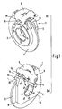
- the floating caliper disc brake 1 shown in the figures for a motor vehicle comprises a vehicle-fixed holder 2 and a sliding to the holder 2 mounted floating caliper 3.
- the holder 2 is either screwed fixed to the vehicle as shown or directly integrated into a steering knuckle, not shown.
- a floating caliper 3 On the holder 2 is a floating caliper 3 relative to the axial direction of a brake disc 5 is slidably mounted on a single bolt guide 4.
- a bolt guide 4 usually includes a guide pin which is attached either to the holder 2 or floating caliper 3 and slidably into an associated guide bore in each case other component, ie floating caliper 3 or holder extends.
- the floating caliper 3 engages over a brake disk 5 as well as on both sides of the brake disk 5 arranged brake pads 6, 7, which are brought into friction with a friction surface 8 of the brake disk 5 during braking.
- an actuating device 9 is integrated on the vehicle-related axially inner side of the brake disc 5.
- a floating caliper 3 is shown with a hydraulic actuator 9, wherein in principle for an inventive arrangement, the type of Zuwelt the floating caliper disc brake 1 during a brake operation is secondary. Alternatively, for example, find an electric, pneumatic or mechanical actuator 9 use. There are also mixed forms of various actuators conceivable, as used for example in combined floating caliper disc brakes for operating and parking brake operation.
- the support and displaceable guidance of the floating caliper 3 takes place next to the pin guide 4 via circumferential projections 12 in the circumferential direction 14, which cooperate with the holder arms 13.
- the projections 14 are formed on the axial outer side of the floating caliper 3 and are supported and guided both in the radial direction 11 and in the circumferential direction 12 relative to the holder arms 13.
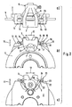
- a spring 15 is provided at least on one side, preferably on both sides, which is fastened to the holder arm 13 with a fastening section 16.
- contact surfaces 17, 18 are integrally formed on the attachment portion 16, which extend between the holder arm 13 and floating caliper 3 and serve to guide and support the floating caliper 3.
- the contact surfaces 17, 18 thus facilitate both the support of the floating caliper 3 in the circumferential direction 12 and its guide in the axial direction 10.
- the contact surfaces 17, 18 thus act as an intermediate layer and prevent direct contact of floating caliper 3 and holder 2.
- the use of different Materials for floating caliper 3 and 2 holder facilitates and, with the use of appropriate spring materials, the formation of corrosion difficult. In particular, this simplifies the use of light metal materials, such. As aluminum, for the floating caliper.
- the spring 15 comprises a spring portion 19, with which the floating caliper 3 is clamped rattle-free relative to the holder 2 or holder arm 13. This rattle-free spring preload refers to both the radial 11 and the circumferential direction 12. The spring preload thus prevents the preservation of the relative displacement between the floating caliper 3 and holder 2 the Emergence of unwanted brake noise.
- Another design feature that allows a weight-saving "slim" interpretation of the floating caliper disc brake 1 relates to the support of the resulting brake pads 6, 7 brake circumferential forces.
- the axially inner first brake pad 6, which acts directly on the actuating device 9 with a clamping force acts with L-shaped lateral projections 26 with the holder arms 13 together.
- a fastening section 21 of a spring 20 is also formed between the lateral projections 26 and the holder arms 13.
- corresponding contact surfaces 22, 23 are integrally formed to guide the first brake pad 6 to the holder arms 13 in the axial direction 10 easily displaceable and support in the circumferential direction 12.
- the spring 20 also has a spring portion 24 in order to clamp the first brake pad 6 rattle-free relative to the holder 2 both in the radial direction 11 and in the circumferential direction 12.
- the two springs 15, 20 for guiding and supporting as well as springing both the first brake lining 6 and the floating caliper 3 can be designed either as separate individual parts or as advantageous in the figures as a one-piece combined spring element. This simplifies the handling.
- the springs 15, 20 or the one-piece spring element are respectively fastened to the holder arm 13 via the attachment section 16, 21 by means of a fastening element 25.
- a fastener 25 may, for example, a screw, a rivet, a notched nail or similar be used.
- the axially outer second brake lining 7 abuts the outer floating caliper limb 30.
- axial protrusions 27 are integrally formed on the second brake pad 7, each of which extends in a form-fitting manner into associated recesses 32 within a U-shaped recess 31 of the floating caliper limb 30.
- These projections 27 with recesses 32 allow a support of the brake lining forces occurring on the second brake pad 7 via the floating caliper 3.
Claims (5)
- Frein à disque à étrier flottant pour un véhicule automobile comportant un support (2) solidaire de l'essieu, un étrier flottant (3) monté coulissant sur le support (2) au moyen d'un seul guide à boulon (4) lequel étrier flottant est disposé pivotant autour d'un axe du guide à boulon (4), l'étrier flottant (3) étant soutenu sur le support (2) dans la direction périphérique (12), et comportant des garnitures de frein (6, 7) disposées des deux côtés d'un disque de frein (5), une première garniture de frein (6) étant guidée coulissante sur le support (2) et soutenue et une seconde garniture de frein (7) étant soutenue sur l'étrier flottant (3), caractérisé en ce que sur le support (2) sont formés des bras de support (13) qui dépassent axialement du disque de frein (5), et des saillies (14) sont formées sur un côté extérieur axial de l'étrier flottant (3), lesquelles coopèrent avec les bras de support (13).
- Frein à disque à étrier flottant selon la revendication 1, caractérisé en ce que l'étrier flottant (3) est tendu dans la direction périphérique (12), au moins d'un côté, au moyen d'un ressort (15), par rapport au support (2).
- Frein à disque à étrier flottant selon la revendication 2, caractérisé en ce que sur le ressort (15) sont réalisées des surfaces de contact (17, 18) pour le guidage et le soutien de l'étrier flottant (3).
- Frein à disque à étrier flottant selon l'une des revendications 2 ou 3, caractérisé en ce que le ressort (15, 20) tend la première garniture de frein (6) par rapport au support (2).
- Frein à disque à étrier flottant selon l'une des revendications 2 à 4, caractérisé en ce que sur le ressort (15, 20) sont réalisées des surfaces de contact (22, 23) pour le guidage et le soutien de la première garniture de frein (3) sur le support (2).
Applications Claiming Priority (3)
| Application Number | Priority Date | Filing Date | Title |
|---|---|---|---|
| DE10158672 | 2001-11-30 | ||
| DE2001158672 DE10158672A1 (de) | 2001-11-30 | 2001-11-30 | Schwimmsattel-Scheibenbremse für ein Kraftfahrzeug |
| PCT/EP2002/010930 WO2003046401A1 (fr) | 2001-11-30 | 2002-09-30 | Frein a disque a etrier flottant pour vehicule automobile |
Publications (2)
| Publication Number | Publication Date |
|---|---|
| EP1454076A1 EP1454076A1 (fr) | 2004-09-08 |
| EP1454076B1 true EP1454076B1 (fr) | 2008-01-16 |
Family
ID=7707443
Family Applications (1)
| Application Number | Title | Priority Date | Filing Date |
|---|---|---|---|
| EP02774667A Expired - Lifetime EP1454076B1 (fr) | 2001-11-30 | 2002-09-30 | Frein a disque a etrier flottant pour vehicule automobile |
Country Status (3)
| Country | Link |
|---|---|
| EP (1) | EP1454076B1 (fr) |
| DE (2) | DE10158672A1 (fr) |
| WO (1) | WO2003046401A1 (fr) |
Cited By (1)
| Publication number | Priority date | Publication date | Assignee | Title |
|---|---|---|---|---|
| DE202013101406U1 (de) | 2013-04-02 | 2013-05-06 | Haldex Brake Products Ab | Scheibenbremse |
Family Cites Families (5)
| Publication number | Priority date | Publication date | Assignee | Title |
|---|---|---|---|---|
| US3330385A (en) * | 1965-06-15 | 1967-07-11 | Kelsey Hayes Co | Spot-type disk brake and support means |
| US3942611A (en) * | 1974-05-20 | 1976-03-09 | The Bendix Corporation | Disc brake and mounting structure therefor |
| JPS6225550Y2 (fr) * | 1979-03-24 | 1987-06-30 | ||
| IT1160157B (it) * | 1983-01-10 | 1987-03-04 | Brembo Spa | Complesso di freno a disco |
| DE4126339C2 (de) * | 1991-08-09 | 2002-04-04 | Continental Teves Ag & Co Ohg | Schwimmsattel-Teilbelagscheibenbremse für Hochleistungsfahrzeuge |
-
2001
- 2001-11-30 DE DE2001158672 patent/DE10158672A1/de not_active Withdrawn
-
2002
- 2002-09-30 WO PCT/EP2002/010930 patent/WO2003046401A1/fr active IP Right Grant
- 2002-09-30 DE DE50211575T patent/DE50211575D1/de not_active Expired - Lifetime
- 2002-09-30 EP EP02774667A patent/EP1454076B1/fr not_active Expired - Lifetime
Cited By (2)
| Publication number | Priority date | Publication date | Assignee | Title |
|---|---|---|---|---|
| DE202013101406U1 (de) | 2013-04-02 | 2013-05-06 | Haldex Brake Products Ab | Scheibenbremse |
| WO2014161679A1 (fr) | 2013-04-02 | 2014-10-09 | Haldex Brake Products Ab | Frein à disques |
Also Published As
| Publication number | Publication date |
|---|---|
| DE50211575D1 (de) | 2008-03-06 |
| WO2003046401A1 (fr) | 2003-06-05 |
| EP1454076A1 (fr) | 2004-09-08 |
| DE10158672A1 (de) | 2003-06-12 |
Similar Documents
| Publication | Publication Date | Title |
|---|---|---|
| EP0341610B1 (fr) | Frein à disque à garniture partielle | |
| EP1532380B1 (fr) | Support de frein a disque a etrier flottant pourvu d'un ressort de guidage de garnitures de frein | |
| EP1832777B1 (fr) | Frein à disque | |
| DE112006002895B4 (de) | Elektrische Betätigungseinheit für eine Fahrzeugbremsanordnung | |
| DE102007015510B4 (de) | Fahrzeugscheibenbremse mit integrierter Trommelbremse und Verfahren zu ihrer Herstellung | |
| DE3017307C2 (de) | Führung für die Tragplatten von Bremsbelägen einer Teilbelagscheibenbremse | |
| DE10131274A1 (de) | Bremsträger- und Bremsklotzanordnung zur Verwendung in einer Scheibenbremse | |
| DE2307537C3 (de) | Kombinierte Innen- und Außenbackenbremse | |
| DE2650767A1 (de) | Hydraulisch betaetigte scheibenbremse fuer fahrzeuge | |
| DE3508039A1 (de) | Innen umgriffene scheibenbremse, insbesondere fuer kraftfahrzeuge | |
| DE102007057614A1 (de) | Ein Parkbrems- und Aktormechanismus | |
| DE10238734A1 (de) | Schwimmsattel-Scheibenbremse mit einer Bremsbelagfeder | |
| DE102009007201A1 (de) | Scheibenbremse mit einer Federanordnung | |
| DE102004017383A1 (de) | Elektromechanische Scheibenbremse | |
| EP1516131B1 (fr) | Frein a disque a etrier flottant | |
| EP1158196A2 (fr) | Frein à disque de garniture partielle avec support de patin | |
| EP1454076B1 (fr) | Frein a disque a etrier flottant pour vehicule automobile | |
| EP0597893B1 (fr) | Frein a disque a etrier flottant a agencement confortable des segments | |
| DE19626296B4 (de) | Schwimmsattel-Teilbelagscheibenbremse | |
| EP1227260B1 (fr) | Frein à disque à étrier coulissant avec ensemble de ressort | |
| DE3539602A1 (de) | Innenumgreifende scheibenbremse, insbesondere fuer kraftfahrzeuge | |
| EP0469310A1 (fr) | Patin de frein pour freins à disque à garniture partielle | |
| EP1676044B1 (fr) | Frein a disque a garniture partielle dote d'un ensemble ressort | |
| DE60213220T3 (de) | Scheibenbremse | |
| DE19540757B4 (de) | Teilbelag-Festsattelscheibenbremse, insbesondere für Kraftfahrzeuge |
Legal Events
| Date | Code | Title | Description |
|---|---|---|---|
| PUAI | Public reference made under article 153(3) epc to a published international application that has entered the european phase |
Free format text: ORIGINAL CODE: 0009012 |
|
| 17P | Request for examination filed |
Effective date: 20040630 |
|
| AK | Designated contracting states |
Kind code of ref document: A1 Designated state(s): AT BE CH CY DE DK ES FI FR GB GR IE IT LI LU MC NL PT SE TR |
|
| 17Q | First examination report despatched |
Effective date: 20060918 |
|
| GRAP | Despatch of communication of intention to grant a patent |
Free format text: ORIGINAL CODE: EPIDOSNIGR1 |
|
| GRAS | Grant fee paid |
Free format text: ORIGINAL CODE: EPIDOSNIGR3 |
|
| GRAA | (expected) grant |
Free format text: ORIGINAL CODE: 0009210 |
|
| AK | Designated contracting states |
Kind code of ref document: B1 Designated state(s): DE FR IT |
|
| REF | Corresponds to: |
Ref document number: 50211575 Country of ref document: DE Date of ref document: 20080306 Kind code of ref document: P |
|
| RAP2 | Party data changed (patent owner data changed or rights of a patent transferred) |
Owner name: CONTINENTAL TEVES AG & CO. OHG |
|
| ET | Fr: translation filed | ||
| PLBE | No opposition filed within time limit |
Free format text: ORIGINAL CODE: 0009261 |
|
| STAA | Information on the status of an ep patent application or granted ep patent |
Free format text: STATUS: NO OPPOSITION FILED WITHIN TIME LIMIT |
|
| 26N | No opposition filed |
Effective date: 20081017 |
|
| PG25 | Lapsed in a contracting state [announced via postgrant information from national office to epo] |
Ref country code: IT Free format text: LAPSE BECAUSE OF FAILURE TO SUBMIT A TRANSLATION OF THE DESCRIPTION OR TO PAY THE FEE WITHIN THE PRESCRIBED TIME-LIMIT Effective date: 20080116 |
|
| REG | Reference to a national code |
Ref country code: FR Ref legal event code: PLFP Year of fee payment: 15 |
|
| REG | Reference to a national code |
Ref country code: FR Ref legal event code: PLFP Year of fee payment: 16 |
|
| PGFP | Annual fee paid to national office [announced via postgrant information from national office to epo] |
Ref country code: FR Payment date: 20170928 Year of fee payment: 16 |
|
| PGFP | Annual fee paid to national office [announced via postgrant information from national office to epo] |
Ref country code: DE Payment date: 20170930 Year of fee payment: 16 |
|
| REG | Reference to a national code |
Ref country code: DE Ref legal event code: R119 Ref document number: 50211575 Country of ref document: DE |
|
| PG25 | Lapsed in a contracting state [announced via postgrant information from national office to epo] |
Ref country code: DE Free format text: LAPSE BECAUSE OF NON-PAYMENT OF DUE FEES Effective date: 20190402 |
|
| PG25 | Lapsed in a contracting state [announced via postgrant information from national office to epo] |
Ref country code: FR Free format text: LAPSE BECAUSE OF NON-PAYMENT OF DUE FEES Effective date: 20180930 |