EP1454076B1 - Floating caliper disk brake for a motor vehicle - Google Patents
Floating caliper disk brake for a motor vehicle Download PDFInfo
- Publication number
- EP1454076B1 EP1454076B1 EP02774667A EP02774667A EP1454076B1 EP 1454076 B1 EP1454076 B1 EP 1454076B1 EP 02774667 A EP02774667 A EP 02774667A EP 02774667 A EP02774667 A EP 02774667A EP 1454076 B1 EP1454076 B1 EP 1454076B1
- Authority
- EP
- European Patent Office
- Prior art keywords
- brake
- holder
- floating caliper
- floating
- caliper
- Prior art date
- Legal status (The legal status is an assumption and is not a legal conclusion. Google has not performed a legal analysis and makes no representation as to the accuracy of the status listed.)
- Expired - Lifetime
Links
- 230000005540 biological transmission Effects 0.000 description 4
- 230000015572 biosynthetic process Effects 0.000 description 3
- 239000000463 material Substances 0.000 description 3
- 238000010276 construction Methods 0.000 description 2
- 230000007797 corrosion Effects 0.000 description 2
- 238000005260 corrosion Methods 0.000 description 2
- 238000006073 displacement reaction Methods 0.000 description 2
- 230000036316 preload Effects 0.000 description 2
- 229910052782 aluminium Inorganic materials 0.000 description 1
- XAGFODPZIPBFFR-UHFFFAOYSA-N aluminium Chemical compound [Al] XAGFODPZIPBFFR-UHFFFAOYSA-N 0.000 description 1
- 238000006243 chemical reaction Methods 0.000 description 1
- 230000003750 conditioning effect Effects 0.000 description 1
- 239000007769 metal material Substances 0.000 description 1
- 238000004321 preservation Methods 0.000 description 1
Images
Classifications
-
- F—MECHANICAL ENGINEERING; LIGHTING; HEATING; WEAPONS; BLASTING
- F16—ENGINEERING ELEMENTS AND UNITS; GENERAL MEASURES FOR PRODUCING AND MAINTAINING EFFECTIVE FUNCTIONING OF MACHINES OR INSTALLATIONS; THERMAL INSULATION IN GENERAL
- F16D—COUPLINGS FOR TRANSMITTING ROTATION; CLUTCHES; BRAKES
- F16D65/00—Parts or details
- F16D65/02—Braking members; Mounting thereof
- F16D65/04—Bands, shoes or pads; Pivots or supporting members therefor
- F16D65/092—Bands, shoes or pads; Pivots or supporting members therefor for axially-engaging brakes, e.g. disc brakes
- F16D65/095—Pivots or supporting members therefor
- F16D65/097—Resilient means interposed between pads and supporting members or other brake parts
- F16D65/0973—Resilient means interposed between pads and supporting members or other brake parts not subjected to brake forces
- F16D65/0974—Resilient means interposed between pads and supporting members or other brake parts not subjected to brake forces acting on or in the vicinity of the pad rim in a direction substantially transverse to the brake disc axis
- F16D65/0977—Springs made from sheet metal
-
- F—MECHANICAL ENGINEERING; LIGHTING; HEATING; WEAPONS; BLASTING
- F16—ENGINEERING ELEMENTS AND UNITS; GENERAL MEASURES FOR PRODUCING AND MAINTAINING EFFECTIVE FUNCTIONING OF MACHINES OR INSTALLATIONS; THERMAL INSULATION IN GENERAL
- F16D—COUPLINGS FOR TRANSMITTING ROTATION; CLUTCHES; BRAKES
- F16D55/00—Brakes with substantially-radial braking surfaces pressed together in axial direction, e.g. disc brakes
- F16D55/02—Brakes with substantially-radial braking surfaces pressed together in axial direction, e.g. disc brakes with axially-movable discs or pads pressed against axially-located rotating members
- F16D55/22—Brakes with substantially-radial braking surfaces pressed together in axial direction, e.g. disc brakes with axially-movable discs or pads pressed against axially-located rotating members by clamping an axially-located rotating disc between movable braking members, e.g. movable brake discs or brake pads
- F16D55/224—Brakes with substantially-radial braking surfaces pressed together in axial direction, e.g. disc brakes with axially-movable discs or pads pressed against axially-located rotating members by clamping an axially-located rotating disc between movable braking members, e.g. movable brake discs or brake pads with a common actuating member for the braking members
- F16D55/225—Brakes with substantially-radial braking surfaces pressed together in axial direction, e.g. disc brakes with axially-movable discs or pads pressed against axially-located rotating members by clamping an axially-located rotating disc between movable braking members, e.g. movable brake discs or brake pads with a common actuating member for the braking members the braking members being brake pads
- F16D55/226—Brakes with substantially-radial braking surfaces pressed together in axial direction, e.g. disc brakes with axially-movable discs or pads pressed against axially-located rotating members by clamping an axially-located rotating disc between movable braking members, e.g. movable brake discs or brake pads with a common actuating member for the braking members the braking members being brake pads in which the common actuating member is moved axially, e.g. floating caliper disc brakes
- F16D55/2265—Brakes with substantially-radial braking surfaces pressed together in axial direction, e.g. disc brakes with axially-movable discs or pads pressed against axially-located rotating members by clamping an axially-located rotating disc between movable braking members, e.g. movable brake discs or brake pads with a common actuating member for the braking members the braking members being brake pads in which the common actuating member is moved axially, e.g. floating caliper disc brakes the axial movement being guided by one or more pins engaging bores in the brake support or the brake housing
Definitions
- the invention relates to a floating caliper disc brake for a motor vehicle with an axle-fixed holder on which a floating caliper by means of a single bolt guide is slidably mounted and pivotable about the axis of the pin guide.
- the transmission of the brake circumferential forces is done by conditioning the brake pads on the side mounted in the floating caliper support bolts.
- the voltage applied to both brake pads brake circumferential forces are transmitted with the interposition of the support bolts on the floating caliper.
- This requires a very stable construction of the floating caliper or the support bolts, which runs counter to fundamental efforts for weight savings.
- the described construction of the floating caliper disc brake tends due to insufficient elasticity to the formation of unwanted rattling noises.
- the floating caliper disc brake for a motor vehicle according to claim 1.
- the floating caliper disc brake comprises an axle fixed holder, a slidably mounted by exactly one bolt guide on the holder floating caliper which is pivotally mounted about an axis of the bolt guide, wherein the floating caliper is supported in the circumferential direction on the holder, and on both sides of a brake disc arranged brake pads.
- a first brake pad is slidably guided and supported on the holder and a second brake pad supported on the floating caliper.
- a preferred embodiment of the floating caliper disc brake can be achieved in that on the spring bearing surfaces for guiding and supporting the floating caliper are formed.
- the floating caliper is supported and guided by the multifunctional spring on the holder.
- the spring thus forms an intermediate layer and prevents direct contact of the floating caliper with the holder. With appropriate spring design, this prevents the formation of corrosion between floating caliper and holder basically opens up the use of different materials for holders and floating calipers.
- the spring can be easily designed for good sliding properties on its surface and thus improve the floating caliper guide.
- a useful embodiment of the described floating caliper disc brake provides that the spring braces the first brake pad against the holder.
- This is the brake lining interacting with an actuating device of the floating caliper, which is usually arranged on the axial inner side of the vehicle.
- both a separate spring may be present, which braces only the first brake pad with the holder, as well as a combined spring which braces the first brake pad and the floating caliper against the holder.
- Such a combined spring advantageously reduces the component complexity.
- additional contact surfaces for guiding and supporting the first brake pad are formed on the spring.
- the brake pad guide is improved by extending the spring at least with a portion between the brake pad and the holder.
- the floating caliper disc brake 1 shown in the figures for a motor vehicle comprises a vehicle-fixed holder 2 and a sliding to the holder 2 mounted floating caliper 3.
- the holder 2 is either screwed fixed to the vehicle as shown or directly integrated into a steering knuckle, not shown.
- a floating caliper 3 On the holder 2 is a floating caliper 3 relative to the axial direction of a brake disc 5 is slidably mounted on a single bolt guide 4.
- a bolt guide 4 usually includes a guide pin which is attached either to the holder 2 or floating caliper 3 and slidably into an associated guide bore in each case other component, ie floating caliper 3 or holder extends.
- the floating caliper 3 engages over a brake disk 5 as well as on both sides of the brake disk 5 arranged brake pads 6, 7, which are brought into friction with a friction surface 8 of the brake disk 5 during braking.
- an actuating device 9 is integrated on the vehicle-related axially inner side of the brake disc 5.
- a floating caliper 3 is shown with a hydraulic actuator 9, wherein in principle for an inventive arrangement, the type of Zuwelt the floating caliper disc brake 1 during a brake operation is secondary. Alternatively, for example, find an electric, pneumatic or mechanical actuator 9 use. There are also mixed forms of various actuators conceivable, as used for example in combined floating caliper disc brakes for operating and parking brake operation.
- the support and displaceable guidance of the floating caliper 3 takes place next to the pin guide 4 via circumferential projections 12 in the circumferential direction 14, which cooperate with the holder arms 13.
- the projections 14 are formed on the axial outer side of the floating caliper 3 and are supported and guided both in the radial direction 11 and in the circumferential direction 12 relative to the holder arms 13.
- a spring 15 is provided at least on one side, preferably on both sides, which is fastened to the holder arm 13 with a fastening section 16.
- contact surfaces 17, 18 are integrally formed on the attachment portion 16, which extend between the holder arm 13 and floating caliper 3 and serve to guide and support the floating caliper 3.
- the contact surfaces 17, 18 thus facilitate both the support of the floating caliper 3 in the circumferential direction 12 and its guide in the axial direction 10.
- the contact surfaces 17, 18 thus act as an intermediate layer and prevent direct contact of floating caliper 3 and holder 2.
- the use of different Materials for floating caliper 3 and 2 holder facilitates and, with the use of appropriate spring materials, the formation of corrosion difficult. In particular, this simplifies the use of light metal materials, such. As aluminum, for the floating caliper.
- the spring 15 comprises a spring portion 19, with which the floating caliper 3 is clamped rattle-free relative to the holder 2 or holder arm 13. This rattle-free spring preload refers to both the radial 11 and the circumferential direction 12. The spring preload thus prevents the preservation of the relative displacement between the floating caliper 3 and holder 2 the Emergence of unwanted brake noise.
- Another design feature that allows a weight-saving "slim" interpretation of the floating caliper disc brake 1 relates to the support of the resulting brake pads 6, 7 brake circumferential forces.
- the axially inner first brake pad 6, which acts directly on the actuating device 9 with a clamping force acts with L-shaped lateral projections 26 with the holder arms 13 together.
- a fastening section 21 of a spring 20 is also formed between the lateral projections 26 and the holder arms 13.
- corresponding contact surfaces 22, 23 are integrally formed to guide the first brake pad 6 to the holder arms 13 in the axial direction 10 easily displaceable and support in the circumferential direction 12.
- the spring 20 also has a spring portion 24 in order to clamp the first brake pad 6 rattle-free relative to the holder 2 both in the radial direction 11 and in the circumferential direction 12.
- the two springs 15, 20 for guiding and supporting as well as springing both the first brake lining 6 and the floating caliper 3 can be designed either as separate individual parts or as advantageous in the figures as a one-piece combined spring element. This simplifies the handling.
- the springs 15, 20 or the one-piece spring element are respectively fastened to the holder arm 13 via the attachment section 16, 21 by means of a fastening element 25.
- a fastener 25 may, for example, a screw, a rivet, a notched nail or similar be used.
- the axially outer second brake lining 7 abuts the outer floating caliper limb 30.
- axial protrusions 27 are integrally formed on the second brake pad 7, each of which extends in a form-fitting manner into associated recesses 32 within a U-shaped recess 31 of the floating caliper limb 30.
- These projections 27 with recesses 32 allow a support of the brake lining forces occurring on the second brake pad 7 via the floating caliper 3.
Description
Die Erfindung betrifft eine Schwimmsattel-Scheibenbremse für ein Kraftfahrzeug mit einem achsfesten Halter, an dem ein Schwimmsattel mittels einer einzigen Bolzenführung verschiebbar sowie um die Achse der Bolzenführung schwenkbar gelagert ist.The invention relates to a floating caliper disc brake for a motor vehicle with an axle-fixed holder on which a floating caliper by means of a single bolt guide is slidably mounted and pivotable about the axis of the pin guide.
Aus der
Dokument
Ausgehend davon ist es die Aufgabe der Erfindung eine Schwimmsattel-Scheibenbremse mit nur einer Bolzenführung für den Schwimmsattel anzugeben, die eine verbesserte Führung und Abstützung des Schwimmsattels sowie der Bremsbeläge ermöglicht und gleichzeitig eine gewichtssparende Konstruktion zulässt.Based on this, it is the object of the invention to provide a floating caliper disc brake with only one bolt guide for the floating caliper, which allows improved guidance and support of the floating caliper and the brake pads while allowing a weight-saving design.
Gelöst wird diese Aufgabe durch eine Schwimmsattel-Scheibenbremse für ein Kraftfahrzeug nach Patentanspruch 1. Danach umfasst die Schwimmsattel-Scheibenbremse einen achsfesten Halter, einen mittels genau einer Bolzenführung verschiebbar am Halter gelagerten Schwimmsattel, der um eine Achse der Bolzenführung schwenkbar angeordnet ist, wobei der Schwimmsattel in Umfangsrichtung am Halter abgestützt ist, und beiderseits einer Bremsscheibe angeordneten Bremsbeläge. Zur Vereinfachung der Schwimmsattel- wie auch der Bremsbelagführung ist ein erster Bremsbelag am Halter verschiebbar geführt sowie abgestützt und ein zweiter Bremsbelag am Schwimmsattel abgestützt. An Halter sind Haltearme angeformt, welche die Bremsscheibe axial überragen, und an einer axialen Außenseite des Schwimmsattels Vorsprünge angeformt sind, die mit den Haltearmen zusammenwirken. Damit wird ein Teil der Bremsumfangskräfte über den Schwimmsattel auf den achsfesten Halter übertragen. Die Übertragung der gesamten Bremsumfangskräfte wird demnach auf mehrere Kraftübertragungswege aufgeteilt und erlaubt dadurch insbesondere für den Halter und den Schwimmsattel eine gewichtssparend "schlanke" Gestaltung. Außerdem ergibt sich durch die schwenkbare Anordnung eine statisch bestimmte Lagerung des Schwimmsattels am Halter. Diese Art der Lagerung ist besonders toleranzunempfindlich und verhindert gleichzeitig ein Verklemmen des Schwimmsattels unter Umfangslast innerhalb der Bolzenführung bzw. am Halter.This problem is solved by a floating caliper disc brake for a motor vehicle according to claim 1. Thereafter, the floating caliper disc brake comprises an axle fixed holder, a slidably mounted by exactly one bolt guide on the holder floating caliper which is pivotally mounted about an axis of the bolt guide, wherein the floating caliper is supported in the circumferential direction on the holder, and on both sides of a brake disc arranged brake pads. To simplify the floating saddle as well as the brake pad guide a first brake pad is slidably guided and supported on the holder and a second brake pad supported on the floating caliper. At holder support arms are formed, which project axially beyond the brake disc, and on an axial outer side of the floating caliper projections are formed, which cooperate with the retaining arms. Thus, a portion of the brake circumferential forces on the floating caliper is transmitted to the axle-fixed holder. The transmission of the entire brake circumferential forces is therefore divided into several power transmission paths and thereby allows a weight-saving "slim" design, in particular for the holder and the floating caliper. In addition, results from the pivotal arrangement a statically determined storage of the floating caliper on the holder. This type of storage is particularly insensitive to tolerances and at the same time prevents jamming of the floating caliper under circumferential load within the bolt guide or on the holder.
Eine vorteilhafte Weiterentwicklung der Schwimmsattel-Scheibenbremse ergibt sich dadurch, dass der Schwimmsattel in Umfangsrichtung zumindest einseitig mittels einer Feder gegenüber dem Halter verspannt ist. Damit werden unerwünschte Klappergeräusche während des Bremsbetriebes unterbunden. Die Feder wirkt bezogen auf die Bremsscheibenachse im wesentlichen sowohl in radialer Richtung als auch in Umfangsrichtung und ist insbesondere am Halter befestigt. Die besten Ergebnisse lassen sich mit mehreren Federn auf beiden Halterseiten in Umfangsrichtung erzielen.An advantageous further development of the floating caliper disc brake results from the fact that the floating caliper in the circumferential direction at least on one side by means of a spring is braced against the holder. This prevents unwanted rattling noises during braking operation. The spring acts relative to the brake disc axis substantially both in the radial direction and in the circumferential direction and is in particular attached to the holder. The best results can be achieved with several springs on both sides of the holder in the circumferential direction.
Eine bevorzugte Ausführung der Schwimmsattel-Scheibenbremse lässt sich dadurch erreichen, dass an der Feder Anlageflächen zur Führung und Abstützung des Schwimmsattels ausgebildet sind. Dabei ist der Schwimmsattel über die multifunktionale Feder am Halter abgestützt und geführt. Die Feder bildet somit eine Zwischenlage und verhindert eine direkte Berührung des Schwimmsattels mit dem Halter. Bei entsprechender Federgestaltung verhindert dies die Entstehung von Korrosion zwischen Schwimmsattel und Halter eröffnet grundsätzlich die Verwendung unterschiedlicher Materialien für Halter und Schwimmsattel. Die Feder kann auf einfachem Wege gezielt auf gute Gleiteigenschaften an ihrer Oberfläche ausgelegt werden und demnach die Schwimmsattelführung verbessern.A preferred embodiment of the floating caliper disc brake can be achieved in that on the spring bearing surfaces for guiding and supporting the floating caliper are formed. The floating caliper is supported and guided by the multifunctional spring on the holder. The spring thus forms an intermediate layer and prevents direct contact of the floating caliper with the holder. With appropriate spring design, this prevents the formation of corrosion between floating caliper and holder basically opens up the use of different materials for holders and floating calipers. The spring can be easily designed for good sliding properties on its surface and thus improve the floating caliper guide.
Eine sinnvolle Ausführungsform der beschriebenen Schwimmsattel-Scheibenbremse sieht vor, dass die Feder den ersten Bremsbelag gegenüber dem Halter verspannt. Hierbei handelt es sich um den mit einer Betätigungsvorrichtung des Schwimmsattels zusammenwirkenden Bremsbelag, der fahrzeugbezogen üblicherweise auf der axialen Innenseite angeordnet ist. Dabei kann sowohl eine separate Feder vorhanden sein, die nur den ersten Bremsbelag mit dem Halter verspannt, als auch eine kombinierte Feder die den ersten Bremsbelag und den Schwimmsattel gegenüber dem Halter verspannt. Eine solche kombinierte Feder reduziert vorteilhaft den Bauteilaufwand. In Erweiterung dieser Multifunktionalität sind an der Feder zusätzlich Anlageflächen zur Führung und Abstützung des ersten Bremsbelages ausgebildet sind. Damit wird auch die Bremsbelagführung verbessert, indem sich die Feder zumindest mit einem Abschnitt zwischen dem Bremsbelag und dem Halter erstreckt.A useful embodiment of the described floating caliper disc brake provides that the spring braces the first brake pad against the holder. This is the brake lining interacting with an actuating device of the floating caliper, which is usually arranged on the axial inner side of the vehicle. In this case, both a separate spring may be present, which braces only the first brake pad with the holder, as well as a combined spring which braces the first brake pad and the floating caliper against the holder. Such a combined spring advantageously reduces the component complexity. In extension of this multi-functionality additional contact surfaces for guiding and supporting the first brake pad are formed on the spring. Thus, the brake pad guide is improved by extending the spring at least with a portion between the brake pad and the holder.
Weitere sinnvolle Detailmerkmale der Erfindung sind dem Ausführungsbeispiel in den Figuren zu entnehmen und werden im folgenden näher erläutert.Further meaningful detail features of the invention can be found in the embodiment in the figures and are explained in more detail below.
Es zeigt:
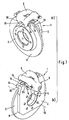
- Fig.1
- zwei räumliche Ansichten einer Schwimmsattel-Scheibenbremse nur einer Bolzenführung für den Schwimmsattel und erfindungsgemäßer Abstützung sowie Führung mittels Federn;
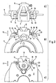
- Fig.2
- drei weitere Ansichten der Schwimmsattel-Scheibenbremse aus Figur 1.
- Fig.1
- two spatial views of a floating caliper disc brake only one bolt guide for the floating caliper and inventive support and leadership by means of springs;
- Fig.2
- three further views of the floating caliper disc brake of Figure 1.
Die in den Figuren dargestellte Schwimmsattel-Scheibenbremse 1 für ein Kraftfahrzeug umfasst einen fahrzeugfesten Halter 2 sowie einen verschiebbar zum Halter 2 gelagerten Schwimmsattel 3. Der Halter 2 ist dabei entweder wie dargestellt fahrzeugfest verschraubt oder aber unmittelbar in einen nicht gezeigten Achsschenkel integriert.The floating caliper disc brake 1 shown in the figures for a motor vehicle comprises a vehicle-fixed
Am Halter 2 ist über eine einzelne Bolzenführung 4 ein Schwimmsattel 3 bezogen auf die Achsrichtung einer Bremsscheibe 5 verschiebbar gelagert. Eine solche Bolzenführung 4 enthält üblicherweise einen Führungsbolzen, der entweder am Halter 2 oder Schwimmsattel 3 befestigt ist und sich verschiebbar in eine zugehörige Führungsbohrung im jeweils anderen Bauteil, d. h. Schwimmsattel 3 oder Halter erstreckt. Der Schwimmsattel 3 übergreift eine Bremsscheibe 5 sowie beiderseits der Bremsscheibe 5 angeordnete Bremsbeläge 6, 7, die bei Bremsbetätigung in Reibanlage mit einer Reibfläche 8 der Bremsscheibe 5 gebracht werden. In den Schwimmsattel 3 ist auf der fahrzeugbezogen axial innenliegenden Seite der Bremsscheibe 5 eine Betätigungsvorrichtung 9 integriert. Diese dient der direkten Beaufschlagung eines ersten Bremsbelages 6 mit einer Bremsenzuspannkraft, während der gegenüberliegende zweite Bremsbelag 7 durch Verschiebung des Schwimmsattels 3 infolge Reaktionskraft gegen die Bremsscheibe 5 gedrückt wird. In den Figuren ist ein Schwimmsattel 3 mit einer hydraulischen Betätigungsvorrichtung 9 gezeigt, wobei grundsätzlich für eine erfindungsgemäße Anordnung die Art der Zuspannung der Schwimmsattel-Scheibenbremse 1 während einer Bremsbetätigung nebensächlich ist. Alternativ kann beispielsweise auch eine elektrische, pneumatische oder mechanische Betätigungsvorrichtung 9 Verwendung finden. Es sind auch Mischformen der verschiedenartiger Betätigungsvorrichtungen denkbar, wie sie beispielsweise bei kombinierten Schwimmsattel-Scheibenbremsen zur Betriebs- sowie zur Feststellbremsbetätigung eingesetzt werden.On the
Vor allem aus Gründen der Gewichtseinsparung wurden die Anbindungsstellen des verschiebbar angeordneten Schwimmsattels 3 zum Halter 2 auf das Notwendigste reduziert. Dazu ist nur eine einzige Bolzenführung 4 vorgesehen mittels der der Schwimmsattel 3 in Zuspannrichtung bzw. parallel zur Achsrichtung 10 der Bremsscheibe 5 verschiebbar am Halter 2 gelagert ist. Damit ist der Schwimmsattel 3 um die Achse der Bolzenführung 4 schwenkbar am Halter 2 angeordnet (siehe Figur 2c). In Umfangsrichtung 12 stützt sich der Schwimmsattel 3 zur Übertragung auftretender Bremsumfangskräfte am Halter 2 ab. Dazu sind am Halter 2 Halterarme 13 angeformt, die die Bremsscheibe 5 axial überragen. Die Abstützung sowie verschiebbare Führung des Schwimmsattels 3 erfolgt neben der Bolzenführung 4 über in Umfangsrichtung 12 seitliche Vorsprünge 14, die mit den Halterarmen 13 zusammenwirken. Die Vorsprünge 14 sind dabei an der axialen Außenseite des Schwimmsattels 3 angeformt und sind sowohl in Radialrichtung 11 als auch in Umfangsrichtung 12 gegenüber den Halterarmen 13 abgestützt und geführt. Zur Verbesserung der Führungseigenschaften des Schwimmsattels 3 ist zumindest einseitig, vorzugsweise beidseitig, eine Feder 15 vorgesehen, die mit einem Befestigungsabschnitt 16 am Halterarm 13 befestigt ist. Dabei sind am Befestigungsabschnitt 16 gleichzeitig Anlageflächen 17, 18 angeformt, die sich zwischen Halterarm 13 und Schwimmsattel 3 erstrecken und der Führung sowie Abstützung des Schwimmsattels 3 dienen. Die Anlageflächen 17, 18 erleichtern damit sowohl die Abstützung des Schwimmsattels 3 in Umfangsrichtung 12 als auch dessen Führung in Achsrichtung 10. Die Anlageflächen 17, 18 wirken somit als Zwischenlage und verhindern einen direkten Kontakt von Schwimmsattel 3 und Halter 2. Dadurch wird die Verwendung unterschiedlicher Materialien für Schwimmsattel 3 und Halter 2 erleichtert und, bei Verwendung entsprechender Federwerkstoffe, die Entstehung von Korrosion erschwert. Insbesondere vereinfacht dies den Einsatz von Leichtmetallwerkstoffen, wie z. B. Aluminium, für den Schwimmsattel. Darüber hinaus umfasst die Feder 15 einen Federabschnitt 19, mit dem der Schwimmsattel 3 klapperfrei gegenüber dem Halter 2 bzw. Halterarm 13 verspannt wird. Diese klapperfrei Federvorspannung bezieht sowohl auf die Radial- 11 als auch die Umfangsrichtung 12. Die Federvorspannung verhindert somit unter Erhaltung der relativen Verschiebbarkeit zwischen Schwimmsattel 3 und Halter 2 die Entstehung unerwünschter Bremsgeräusche.Mainly for reasons of weight savings, the attachment points of the slidably arranged floating
Ein weiteres Konstruktionsmerkmal, das eine gewichtssparend "schlanke" Auslegung der Schwimmsattel-Scheibenbremse 1 ermöglicht betrifft die Abstützung der an den Bremsbelägen 6, 7 entstehenden Bremsumfangskräften. Der axial innenliegende erste Bremsbelag 6, der direkt von der Betätigungsvorrichtung 9 mit einer Zuspannkraft beaufschlagt wirkt mit L-förmigen seitlichen Ansätzen 26 mit den Halterarmen 13 zusammen. Analog zu den Vorsprüngen 14 des Schwimmsattels 3 ist auch zwischen den seitlichen Ansätzen 26 und den Halterarmen 13 jeweils ein Befestigungsabschnitt 21 einer Feder 20 ausgebildet. Am Befestigungsabschnitt 21 sind entsprechend Anlageflächen 22, 23 angeformt, um den ersten Bremsbelag 6 an den Halterarmen 13 in Achsrichtung 10 leicht verschiebbar zu führen und in Umfangsrichtung 12 abzustützen. Insgesamt werden die am ersten Bremsbelag 6 entstehenden Bremsumfangskraft unter Zwischenschaltung der Anlageflächen 22 direkt über den fahrzeugfesten Halter 2 abgeführt. Weiterhin weist die Feder 20 auch einen Federabschnitt 24 auf, um den ersten Bremsbelag 6 sowohl in Radialrichtung 11 als auch in Umfangsrichtung 12 klapperfrei gegenüber dem Halter 2 zu verspannen.Another design feature that allows a weight-saving "slim" interpretation of the floating caliper disc brake 1 relates to the support of the resulting
Die beiden Federn 15, 20 zur Führung und Abstützung sowie Befederung sowohl des ersten Bremsbelages 6 als auch des Schwimmsattels 3 können entweder als separate Einzelteile oder wie in den Figuren vorteilhaft als einteiliges kombiniertes Federelement ausgeführt werden. Dies vereinfacht die Handhabung. Insbesondere sind die Federn 15, 20 bzw. das einteilige Federelement jeweils über den Befestigungsabschnitt 16, 21 mittels eines Befestigungselementes 25 am Halterarm 13 befestigt. Als Befestigungselement 25 kann beispielsweise eine Schraube, ein Niet, ein Kerbnagel oder ähnliches verwendet werden.The two springs 15, 20 for guiding and supporting as well as springing both the
Der axial außenliegende zweite Bremsbelag 7 liegt am außenliegenden Schwimmsattelschenkel 30 an. Dazu sind am zweiten Bremsbelag 7 axiale Vorsprünge 27 angeformt, die sich jeweils formschlüssig in zugehörige Aussparungen 32 innerhalb einer U-förmigen Ausnehmung 31 des Schwimmsattelschenkels 30 erstrecken. Diese Vorsprünge 27 mit Aussparungen 32 gestatten eine Abstützung der am zweiten Bremsbelag 7 auftretenden Bremsumfangkräfte über den Schwimmsattel 3. Bezogen auf den zweiten Bremsbelag verläuft der Kraftfluss bei der Übertragung der Bremsumfangkräfte während einer Bremsbetätigung ausgehend vom Bremsbelag 7 über den Schwimmsattel 3, die seitlichen Vorsprünge 14 und die Halterarme 13 hin zum fahrzeugfesten Halter 2. Insgesamt werden die an den beiden Bremsbelägen 6, 7 anliegenden Bremsumfangskräfte somit anteilig in den Halter 2 bzw. den Schwimmsattel 3 abgeführt. Dieser aufgeteilte Kraftfluss erlaubt eine optimierte, insbesondere gewichtssparende, Auslegung der einzelnen Komponenten der Schwimmsattel-Scheibenbremse.The axially outer second brake lining 7 abuts the outer floating
Claims (5)
- Floating-caliper disc brake for a motor vehicle with a holder (2) fixed to a shaft, with a floating caliper (3) that is slidably mounted on the holder (2) by means of exactly one pin guide (4), the said floating caliper being arranged so as to be tiltable about an axis of the pin guide (4), with the floating caliper (3) being supported in a circumferential direction (12) at the holder (2), and with brake pads (6, 7) arranged on either side of a brake disc (5), with a first brake pad (6) being slidably guided and supported on the holder (2), while a second brake pad (7) is supported on the floating caliper (3),
characterized in that holder arms (13) are shaped at the holder (2) and project axially over the brake disc (5), and projections (14) are shaped at an axial outside surface of the floating caliper (3) and cooperate with the holder arms (13). - Floating-caliper disc brake as claimed in claim 1,
characterized in that the floating caliper (3) is clamped in relation to the holder (2) in the circumferential direction (12) at least on one side by means of a spring (15). - Floating-caliper disc brake as claimed in claim 2,
characterized in that the spring (15) is provided with abutment surfaces (17, 18) for guiding and supporting the floating caliper (3). - Floating-caliper disc brake as claimed in any one of claims 2 to 3,
characterized in that the spring (15, 20) clamps the first brake pad (6) in relation to the holder (2). - Floating-caliper disc brake as claimed in any one of claims 2 to 4,
characterized in that abutment surfaces (22, 23) are provided on the spring (15, 20) for guiding and supporting the first brake pad (3) on the holder (2).
Applications Claiming Priority (3)
| Application Number | Priority Date | Filing Date | Title |
|---|---|---|---|
| DE10158672 | 2001-11-30 | ||
| DE2001158672 DE10158672A1 (en) | 2001-11-30 | 2001-11-30 | Floating caliper disc brake for a motor vehicle |
| PCT/EP2002/010930 WO2003046401A1 (en) | 2001-11-30 | 2002-09-30 | Floating caliper disk brake for a motor vehicle |
Publications (2)
| Publication Number | Publication Date |
|---|---|
| EP1454076A1 EP1454076A1 (en) | 2004-09-08 |
| EP1454076B1 true EP1454076B1 (en) | 2008-01-16 |
Family
ID=7707443
Family Applications (1)
| Application Number | Title | Priority Date | Filing Date |
|---|---|---|---|
| EP02774667A Expired - Lifetime EP1454076B1 (en) | 2001-11-30 | 2002-09-30 | Floating caliper disk brake for a motor vehicle |
Country Status (3)
| Country | Link |
|---|---|
| EP (1) | EP1454076B1 (en) |
| DE (2) | DE10158672A1 (en) |
| WO (1) | WO2003046401A1 (en) |
Cited By (1)
| Publication number | Priority date | Publication date | Assignee | Title |
|---|---|---|---|---|
| DE202013101406U1 (en) | 2013-04-02 | 2013-05-06 | Haldex Brake Products Ab | disc brake |
Family Cites Families (5)
| Publication number | Priority date | Publication date | Assignee | Title |
|---|---|---|---|---|
| US3330385A (en) * | 1965-06-15 | 1967-07-11 | Kelsey Hayes Co | Spot-type disk brake and support means |
| US3942611A (en) * | 1974-05-20 | 1976-03-09 | The Bendix Corporation | Disc brake and mounting structure therefor |
| JPS6225550Y2 (en) * | 1979-03-24 | 1987-06-30 | ||
| IT1160157B (en) * | 1983-01-10 | 1987-03-04 | Brembo Spa | DISC BRAKE COMPLEX |
| DE4126339C2 (en) * | 1991-08-09 | 2002-04-04 | Continental Teves Ag & Co Ohg | Part floating disc brake for high-performance vehicles |
-
2001
- 2001-11-30 DE DE2001158672 patent/DE10158672A1/en not_active Withdrawn
-
2002
- 2002-09-30 WO PCT/EP2002/010930 patent/WO2003046401A1/en active IP Right Grant
- 2002-09-30 EP EP02774667A patent/EP1454076B1/en not_active Expired - Lifetime
- 2002-09-30 DE DE50211575T patent/DE50211575D1/en not_active Expired - Lifetime
Cited By (2)
| Publication number | Priority date | Publication date | Assignee | Title |
|---|---|---|---|---|
| DE202013101406U1 (en) | 2013-04-02 | 2013-05-06 | Haldex Brake Products Ab | disc brake |
| WO2014161679A1 (en) | 2013-04-02 | 2014-10-09 | Haldex Brake Products Ab | Disc brake |
Also Published As
| Publication number | Publication date |
|---|---|
| WO2003046401A1 (en) | 2003-06-05 |
| EP1454076A1 (en) | 2004-09-08 |
| DE50211575D1 (en) | 2008-03-06 |
| DE10158672A1 (en) | 2003-06-12 |
Similar Documents
| Publication | Publication Date | Title |
|---|---|---|
| EP0341610B1 (en) | Spot-type disc brake | |
| EP1532380B1 (en) | Brake holder for a floating-caliper disk brake with a brake pad guide spring | |
| DE112006002895B4 (en) | Electrical actuator for a vehicle brake assembly | |
| EP1832777B1 (en) | Disc brake | |
| DE102007015510B4 (en) | Vehicle disc brake with integrated drum brake and method for its production | |
| DE3017307C2 (en) | Guide for the support plates of the brake linings of a partially lined disc brake | |
| DE10131274A1 (en) | Brake carrier and brake pad assembly for use in a disc brake | |
| DE2307537C3 (en) | Combined inner and outer shoe brake | |
| DE2650767A1 (en) | HYDRAULICALLY ACTUATED DISC BRAKE FOR VEHICLES | |
| DE3508039A1 (en) | Disc brake with engagement on the inside, in particular for motor vehicles | |
| DE102007057614A1 (en) | A parking brake and actuator mechanism | |
| DE10238734A1 (en) | Floating caliper disc brake for motor vehicles has brake lining spring fastened to lining and supported axially relative to brake holder via spring arm | |
| DE102009007201A1 (en) | Disk brake i.e. floating caliper disk brake, for use in motor vehicle brake system, has spring arrangement with radial spring element, which is designed such that assembly of element is enabled when brake lining is mounted | |
| DE102004017383A1 (en) | Electromechanical disc brake | |
| EP1516131B1 (en) | Floating-caliper disk brake | |
| EP1158196A2 (en) | Partially lined disc brake with brake pad support | |
| EP1454076B1 (en) | Floating caliper disk brake for a motor vehicle | |
| EP0597893B1 (en) | Floating caliper disc brake with convenient shoe arrangement | |
| DE19626296B4 (en) | Floating caliper-type disc brake | |
| DE3539602A1 (en) | INTERNAL DISC BRAKE, ESPECIALLY FOR MOTOR VEHICLES | |
| EP1227260B1 (en) | Floating caliper disc brake with spring assembly | |
| EP0469310A1 (en) | Brake pad for spot-type disc brakes | |
| EP1676044B1 (en) | Partially lined disc brake comprising a spring arrangement | |
| DE60213220T3 (en) | disc brake | |
| DE19540757B4 (en) | Part-pad fixed caliper disc brake, in particular for motor vehicles |
Legal Events
| Date | Code | Title | Description |
|---|---|---|---|
| PUAI | Public reference made under article 153(3) epc to a published international application that has entered the european phase |
Free format text: ORIGINAL CODE: 0009012 |
|
| 17P | Request for examination filed |
Effective date: 20040630 |
|
| AK | Designated contracting states |
Kind code of ref document: A1 Designated state(s): AT BE CH CY DE DK ES FI FR GB GR IE IT LI LU MC NL PT SE TR |
|
| 17Q | First examination report despatched |
Effective date: 20060918 |
|
| GRAP | Despatch of communication of intention to grant a patent |
Free format text: ORIGINAL CODE: EPIDOSNIGR1 |
|
| GRAS | Grant fee paid |
Free format text: ORIGINAL CODE: EPIDOSNIGR3 |
|
| GRAA | (expected) grant |
Free format text: ORIGINAL CODE: 0009210 |
|
| AK | Designated contracting states |
Kind code of ref document: B1 Designated state(s): DE FR IT |
|
| REF | Corresponds to: |
Ref document number: 50211575 Country of ref document: DE Date of ref document: 20080306 Kind code of ref document: P |
|
| RAP2 | Party data changed (patent owner data changed or rights of a patent transferred) |
Owner name: CONTINENTAL TEVES AG & CO. OHG |
|
| ET | Fr: translation filed | ||
| PLBE | No opposition filed within time limit |
Free format text: ORIGINAL CODE: 0009261 |
|
| STAA | Information on the status of an ep patent application or granted ep patent |
Free format text: STATUS: NO OPPOSITION FILED WITHIN TIME LIMIT |
|
| 26N | No opposition filed |
Effective date: 20081017 |
|
| PG25 | Lapsed in a contracting state [announced via postgrant information from national office to epo] |
Ref country code: IT Free format text: LAPSE BECAUSE OF FAILURE TO SUBMIT A TRANSLATION OF THE DESCRIPTION OR TO PAY THE FEE WITHIN THE PRESCRIBED TIME-LIMIT Effective date: 20080116 |
|
| REG | Reference to a national code |
Ref country code: FR Ref legal event code: PLFP Year of fee payment: 15 |
|
| REG | Reference to a national code |
Ref country code: FR Ref legal event code: PLFP Year of fee payment: 16 |
|
| PGFP | Annual fee paid to national office [announced via postgrant information from national office to epo] |
Ref country code: FR Payment date: 20170928 Year of fee payment: 16 |
|
| PGFP | Annual fee paid to national office [announced via postgrant information from national office to epo] |
Ref country code: DE Payment date: 20170930 Year of fee payment: 16 |
|
| REG | Reference to a national code |
Ref country code: DE Ref legal event code: R119 Ref document number: 50211575 Country of ref document: DE |
|
| PG25 | Lapsed in a contracting state [announced via postgrant information from national office to epo] |
Ref country code: DE Free format text: LAPSE BECAUSE OF NON-PAYMENT OF DUE FEES Effective date: 20190402 |
|
| PG25 | Lapsed in a contracting state [announced via postgrant information from national office to epo] |
Ref country code: FR Free format text: LAPSE BECAUSE OF NON-PAYMENT OF DUE FEES Effective date: 20180930 |