EP1452749B1 - Dispositif de jonction articulée - Google Patents
Dispositif de jonction articulée Download PDFInfo
- Publication number
- EP1452749B1 EP1452749B1 EP04100727A EP04100727A EP1452749B1 EP 1452749 B1 EP1452749 B1 EP 1452749B1 EP 04100727 A EP04100727 A EP 04100727A EP 04100727 A EP04100727 A EP 04100727A EP 1452749 B1 EP1452749 B1 EP 1452749B1
- Authority
- EP
- European Patent Office
- Prior art keywords
- axis
- suspended structure
- plates
- parts
- suspended
- Prior art date
- Legal status (The legal status is an assumption and is not a legal conclusion. Google has not performed a legal analysis and makes no representation as to the accuracy of the status listed.)
- Expired - Lifetime
Links
- 230000002265 prevention Effects 0.000 claims 1
- 230000000295 complement effect Effects 0.000 description 4
- 230000002093 peripheral effect Effects 0.000 description 4
Images


Classifications
-
- F—MECHANICAL ENGINEERING; LIGHTING; HEATING; WEAPONS; BLASTING
- F16—ENGINEERING ELEMENTS AND UNITS; GENERAL MEASURES FOR PRODUCING AND MAINTAINING EFFECTIVE FUNCTIONING OF MACHINES OR INSTALLATIONS; THERMAL INSULATION IN GENERAL
- F16C—SHAFTS; FLEXIBLE SHAFTS; ELEMENTS OR CRANKSHAFT MECHANISMS; ROTARY BODIES OTHER THAN GEARING ELEMENTS; BEARINGS
- F16C11/00—Pivots; Pivotal connections
- F16C11/04—Pivotal connections
- F16C11/06—Ball-joints; Other joints having more than one degree of angular freedom, i.e. universal joints
-
- F—MECHANICAL ENGINEERING; LIGHTING; HEATING; WEAPONS; BLASTING
- F16—ENGINEERING ELEMENTS AND UNITS; GENERAL MEASURES FOR PRODUCING AND MAINTAINING EFFECTIVE FUNCTIONING OF MACHINES OR INSTALLATIONS; THERMAL INSULATION IN GENERAL
- F16C—SHAFTS; FLEXIBLE SHAFTS; ELEMENTS OR CRANKSHAFT MECHANISMS; ROTARY BODIES OTHER THAN GEARING ELEMENTS; BEARINGS
- F16C11/00—Pivots; Pivotal connections
- F16C11/02—Trunnions; Crank-pins
-
- F—MECHANICAL ENGINEERING; LIGHTING; HEATING; WEAPONS; BLASTING
- F16—ENGINEERING ELEMENTS AND UNITS; GENERAL MEASURES FOR PRODUCING AND MAINTAINING EFFECTIVE FUNCTIONING OF MACHINES OR INSTALLATIONS; THERMAL INSULATION IN GENERAL
- F16C—SHAFTS; FLEXIBLE SHAFTS; ELEMENTS OR CRANKSHAFT MECHANISMS; ROTARY BODIES OTHER THAN GEARING ELEMENTS; BEARINGS
- F16C11/00—Pivots; Pivotal connections
- F16C11/04—Pivotal connections
- F16C11/045—Pivotal connections with at least a pair of arms pivoting relatively to at least one other arm, all arms being mounted on one pin
-
- F—MECHANICAL ENGINEERING; LIGHTING; HEATING; WEAPONS; BLASTING
- F16—ENGINEERING ELEMENTS AND UNITS; GENERAL MEASURES FOR PRODUCING AND MAINTAINING EFFECTIVE FUNCTIONING OF MACHINES OR INSTALLATIONS; THERMAL INSULATION IN GENERAL
- F16C—SHAFTS; FLEXIBLE SHAFTS; ELEMENTS OR CRANKSHAFT MECHANISMS; ROTARY BODIES OTHER THAN GEARING ELEMENTS; BEARINGS
- F16C23/00—Bearings for exclusively rotary movement adjustable for aligning or positioning
- F16C23/10—Bearings, parts of which are eccentrically adjustable with respect to each other
-
- Y—GENERAL TAGGING OF NEW TECHNOLOGICAL DEVELOPMENTS; GENERAL TAGGING OF CROSS-SECTIONAL TECHNOLOGIES SPANNING OVER SEVERAL SECTIONS OF THE IPC; TECHNICAL SUBJECTS COVERED BY FORMER USPC CROSS-REFERENCE ART COLLECTIONS [XRACs] AND DIGESTS
- Y10—TECHNICAL SUBJECTS COVERED BY FORMER USPC
- Y10S—TECHNICAL SUBJECTS COVERED BY FORMER USPC CROSS-REFERENCE ART COLLECTIONS [XRACs] AND DIGESTS
- Y10S403/00—Joints and connections
- Y10S403/08—Radially acting cam or eccentric
-
- Y—GENERAL TAGGING OF NEW TECHNOLOGICAL DEVELOPMENTS; GENERAL TAGGING OF CROSS-SECTIONAL TECHNOLOGIES SPANNING OVER SEVERAL SECTIONS OF THE IPC; TECHNICAL SUBJECTS COVERED BY FORMER USPC CROSS-REFERENCE ART COLLECTIONS [XRACs] AND DIGESTS
- Y10—TECHNICAL SUBJECTS COVERED BY FORMER USPC
- Y10T—TECHNICAL SUBJECTS COVERED BY FORMER US CLASSIFICATION
- Y10T403/00—Joints and connections
- Y10T403/32—Articulated members
- Y10T403/32606—Pivoted
- Y10T403/32861—T-pivot, e.g., wrist pin, etc.
- Y10T403/32893—T-pivot, e.g., wrist pin, etc. including distinct pin retainer
-
- Y—GENERAL TAGGING OF NEW TECHNOLOGICAL DEVELOPMENTS; GENERAL TAGGING OF CROSS-SECTIONAL TECHNOLOGIES SPANNING OVER SEVERAL SECTIONS OF THE IPC; TECHNICAL SUBJECTS COVERED BY FORMER USPC CROSS-REFERENCE ART COLLECTIONS [XRACs] AND DIGESTS
- Y10—TECHNICAL SUBJECTS COVERED BY FORMER USPC
- Y10T—TECHNICAL SUBJECTS COVERED BY FORMER US CLASSIFICATION
- Y10T403/00—Joints and connections
- Y10T403/32—Articulated members
- Y10T403/32606—Pivoted
- Y10T403/32861—T-pivot, e.g., wrist pin, etc.
- Y10T403/32918—T-pivot, e.g., wrist pin, etc. fork and tongue
Definitions
- the invention relates to a compact articulated junction device, provided in particular for being interposed between a bearing structure and a suspended structure.
- the bearing structure then comprises a yoke which projects downwards and on which the upper end of the shackle is articulated by a first axis.
- the lower end of the shackle is articulated by a second axis on a clevis integral with the suspended structure. This last clevis then projects upwards or laterally from the suspended structure.
- This arrangement has the disadvantage of having a large footprint in a vertical direction, due to the presence of the shackle connecting the yokes that project upwards or laterally on the suspended structure and down below the bearing structure.
- the purpose of the invention is precisely to propose a new compact junction device in a vertical direction, suitable for use in place of a traditional shackle for hanging a suspended structure under a supporting structure and transmitting loads. which remain acceptable compared to those transmitted by shackles used on existing devices.
- this object is achieved, at least in part, by the use of an articulated joint device according to claim 1.
- This arrangement according to the invention makes it possible to connect a suspended structure to the supporting structure in a compact manner.
- the suspended structure has the shape of a U-shaped yoke having two parallel plates between which is placed the bearing structure, a first part being mounted in each of the plates of the suspended structure.
- first parts are preferably mounted respectively in each of the two plates of the suspended structure. These first parts then cooperate with the two plates of the suspended structure by surfaces in the form of portions of spheres defining between the plates and said parts a ball-type connection.
- Intermediate pieces forming ball cages can then be fixed in each of the two plates of the suspended structure. These intermediate pieces cooperate by inner surfaces in the form of portions of spheres with outer surfaces in the form of portions of spheres of the first parts.
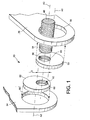
- an articulated junction device 10 is used to pivotally connect a suspended structure 36 to a supporting structure 54.
- the articulated jointing device 10 comprises a single articulation axis 48, a first disc-shaped piece 50 and a second disc-shaped piece 52, which is generally identical. to the first.
- the first disk-shaped piece 50 is mounted in a cylindrical hole 56 passing through the suspended structure 36 along a first axis A1, so that the first piece 50 can rotate freely about this first axis.
- the second disk-shaped piece 52 is mounted in a cylindrical hole 58 which passes through the support structure 54 along a second axis A2, so that the second piece 52 can rotate freely about this second axis.
- the second axis A2 is parallel to the first axis A1.
- the second axis A2 is offset vertically upwards with respect to the first axis A1 of a distance D which may be slightly greater, substantially equal to or even smaller than the diameter of the articulation axis 48.
- the hinge axis 48 has a diameter substantially smaller than that of the parts 50 and 52. It passes through cylindrical holes 60 and 62 respectively machined in the first disk-shaped part 50 and in the second disc-shaped part 52. More specifically, the axis A3 common to the cylindrical holes 60 and 62 and to the hinge axis 48 is eccentric relative to the respective axes A1 and A2 of the parts 50 and 52.
- anti-rotation means are provided between the hinge axis 48 and each of disc-shaped pieces 50 and 52.
- These anti-rotation means comprise, for example, teeth or splines 64 formed on the peripheral surface of the hinge pin 48, engaged with complementary teeth or splines 66 and 68 respectively formed in the cylindrical holes 60 and 62.
- This last arrangement makes it possible to eliminate a degree of freedom in the connection thus obtained between the suspended structure 36 and the supporting structure 54.
- FIG. 2 illustrates a variant of the embodiment illustrated in FIG. 1, in which the suspended structure 36 is in the form of a U-shaped yoke. More specifically, the suspended structure 36 illustrated in FIG. 2 comprises two plane plates 70, parallel to each other. In this case, a cylindrical hole 56 is machined in each of the plates 70, so that the two holes 56 are centered on the same axis A1.
- Each of the cylindrical holes 56 then receives a piece 50 in the form of a disc, through which a cylindrical hole 60, the diameter of which is the same as that of the hinge axis 48, is traversed.
- the tab embodying the carrier structure 54 is placed between the parallel plates 70 of the suspended structure 36, with the disk-shaped part 52 rotatably received in the cylindrical hole 58, as in the embodiment of FIG. figure 1.
- the hinge axis 48 then simultaneously passes through each of the cylindrical holes 60 and 62 respectively formed in the two disk-shaped parts 50 and in the disk-shaped part 52.
- the hinge axis 48 thus ensures the connection between the suspended structure 36 and the supporting structure 54.
- the cohesion of this connection may in particular be provided by flanges, nuts, etc. placed at the ends of the articulation axis 48.
- anti-rotation means such as splines may be provided between the hinge axis 48 and the cylindrical holes 60 and 62 in which this axis is received. This removes a degree of freedom in the connection provided between the suspended structure 36 and the supporting structure 54.
- FIG. 3 shows an improvement to the embodiment variant which has just been described with reference to FIG. 2.
- each of the disk-shaped pieces 50 mounted in the plates 70 of the suspended structure 36 has a peripheral surface 72 in the form of a portion of a sphere.
- Intermediate parts 74 forming cages of ball joints are mounted in each of the plates 70, to define inner surfaces 56 'in the form of portions of spheres. These inner surfaces are complementary to the peripheral surfaces 72 of the disc-shaped pieces 50 and have a common center of rotation.
- the disk-shaped part 52 has an outer peripheral surface 76 in the form of a portion of a sphere, complementary to an inner surface 58 ', in the form of a portion of a sphere, of the supporting structure 54.
- the complementary surfaces 76 and 58 ' connect the pivot axis 48 and the support structure 54 by a ball-type connection.
- the two ball joints thus formed have centers that are offset by a distance D relative to each other in a vertical direction.
- This distance D is the same as in the embodiment of Figure 1 described above.
Landscapes
- Engineering & Computer Science (AREA)
- General Engineering & Computer Science (AREA)
- Mechanical Engineering (AREA)
- Pivots And Pivotal Connections (AREA)
- Massaging Devices (AREA)
- Electrical Discharge Machining, Electrochemical Machining, And Combined Machining (AREA)
- Processing Of Terminals (AREA)
- Toys (AREA)
- Document Processing Apparatus (AREA)
- Pressure Welding/Diffusion-Bonding (AREA)
Description
- L'invention concerne un dispositif compact de jonction articulée, prévu notamment pour être interposé entre une structure portante et une structure suspendue.
- Il est connu de relier une structure suspendue à une structure portante au moyen d'une manille.
- La structure portante comporte alors une chape qui fait saillie vers le bas et sur laquelle l'extrémité haute de la manille est articulée par un premier axe. L'extrémité basse de la manille est articulée par un deuxième axe sur une chape solidaire de la structure suspendue. Cette dernière chape fait alors saillie vers le haut ou latéralement à partir de la structure suspendue.
- Cet agencement a pour inconvénient de présenter un encombrement important dans une direction verticale, du fait de la présence de la manille reliant les chapes qui font saillie vers le haut ou latéralement sur la structure suspendue et vers le bas en dessous de la structure portante.
- L'invention a précisément pour but de proposer un nouveau dispositif de jonction compact dans une direction verticale, apte à être utilisé à la place d'une manille traditionnelle pour l'accrochage d'une structure suspendue sous une structure portante et en transmettant des charges qui restent acceptables par rapport à celles qui sont transmises par les manilles utilisées sur les dispositifs existants.
- Conformément à l'invention, cet objectif est atteint, au moins en partie, grâce à l'utilisation d'un dispositif de jonction articulée conforme à la revendication 1.
- Cet agencement conforme à l'invention permet de relier une structure suspendue à la structure portante, de façon compacte.
- Avantageusement, la structure suspendue a la forme d'une chape en U comportant deux plaques parallèles entre lesquelles est placée la stucture portante, une première pièce étant montée dans chacune des plaques de la structure suspendue.
- Dans ce dernier cas, deux premières pièces sont, de préférence, montées respectivement dans chacune des deux plaques de la structure suspendue. Ces premières pièces coopérent alors avec les deux plaques de la structure suspendue par des surfaces en forme de portions de sphères définissant entre les plaques et lesdites pièces une liaison de type rotule.
- Des pièces intermédiaires formant cages de rotule peuvent alors être fixées dans chacune des deux plaques de la structure suspendue. Ces pièces intermédiaires coopèrent par des surfaces intérieures en forme de portions de sphères avec des surfaces extérieures en forme de portion de sphères des premières pièces.
- On décrira à présent, à titre d'exemple non limitatif, un mode de réalisation préféré de l'invention, en se référant aux dessins annexés, dans lesquels :
- la figure 1 est une vue en perspective éclatée qui illustre un mode de réalisation préféré du dispositif de jonction compact selon l'invention ;
- la figure 2 est une vue en perspective éclatée qui illustre un perfectionnement au mode de réalisation du dispositif de jonction selon l'invention illustré sur la figure 1 ; et
- la figure 3 est une vue en coupe qui représente une variante du perfectionnement illustré sur la figure 2.
- Dans le mode préféré de réalisation de l'invention illustré sur la figure 1, un dispositif de jonction articulée 10 est utilisé pour relier de façon pivotante une structure suspendue 36 à une structure porteuse 54.
- Dans le mode de réalisation de l'invention représenté sur la figure 1, le dispositif de jonction articulée 10 comprend un axe d'articulation unique 48, une première pièce 50 en forme de disque et une deuxième pièce 52 en forme de disque, généralement identique à la première.
- De façon plus précise, la première pièce 50 en forme de disque est montée dans un trou cylindrique 56 traversant la structure suspendue 36 selon un premier axe A1, de telle sorte que la première pièce 50 peut tourner librement autour de ce premier axe.
- De façon comparable, la deuxième pièce 52 en forme de disque est montée dans un trou cylindrique 58 qui traverse la structure porteuse 54 selon un deuxième axe A2, de telle sorte que la deuxième pièce 52 peut tourner librement autour de ce deuxième axe.
- Le deuxième axe A2 est parallèle au premier axe A1. En outre, le deuxième axe A2 est décalé verticalement vers le haut par rapport au premier axe A1 d'une distance D qui peut être légèrement supérieure, sensiblement égale ou même inférieure au diamètre de l'axe d'articulation 48.
- L'axe d'articulation 48 a un diamètre sensiblement inférieur à celui des pièces 50 et 52. Il traverse des trous cylindriques 60 et 62 usinés respectivement dans la première pièce 50 en forme de disque et dans la deuxième pièce 52 en forme de disque. Plus précisément, l'axe A3 commun aux trous cylindriques 60 et 62 et à l'axe d'articulation 48 est excentré par rapport aux axes respectifs A1 et A2 des pièces 50 et 52.
- L'agencement qui vient d'être décrit en se référant à la figure 1 permet de réduire la hauteur du dispositif de jonction, par rapport à une manille classique.
- De préférence et comme on l'a représenté schématiquement sur la figure 1, des moyens anti-rotation sont prévus entre l'axe d'articulation 48 et chacune de pièces 50 et 52 en forme de disque. Ces moyens anti-rotation comprennent, par exemple, des dentures ou des cannelures 64 formées sur la surface périphérique de l'axe d'articulation 48, en prise sur des dentures ou des cannelures complémentaires 66 et 68 formées respectivement dans les trous cylindriques 60 et 62.
- Ce dernier agencement permet de supprimer un degré de liberté dans la liaison ainsi obtenue entre la structure suspendue 36 et la structure porteuse 54.
- La figure 2 illustre une variante du mode de réalisation illustré sur la figure 1, dans laquelle la structure suspendue 36 a la forme d'une chape en U. Plus précisément, la structure suspendue 36 illustrée sur la figure 2 comprend deux plaques planes 70, parallèles entre elles. Dans ce cas, un trou cylindrique 56 est usiné dans chacune des plaques 70, de telle sorte que les deux trous 56 soient centrés sur le même axe A1.
- Chacun des trous cylindriques 56 reçoit alors une pièce 50 en forme de disque, traversée par un trou cylindrique 60 dont le diamètre est le même que celui de l'axe d'articulation 48.
- Dans ce cas, la patte matérialisant la structure porteuse 54 est placée entre les plaques parallèles 70 de la structure suspendue 36, avec la pièce en forme de disque 52 reçue de façon tournante dans le trou cylindrique 58, comme dans le mode de réalisation de la figure 1.
- L'axe d'articulation 48 traverse alors simultanément chacun des trous cylindriques 60 et 62 formés respectivement dans les deux pièces en forme de disque 50 et dans la pièce en forme de disque 52. L'axe d'articulation 48 assure ainsi la liaison entre la structure suspendue 36 et la structure porteuse 54. La cohésion de cette liaison peut notamment être assurée par des flasques, écrous, etc. placés aux extrémités de l'axe d'articulation 48.
- Comme dans le mode de la figure 1, des moyens anti-rotation tels que des cannelures peuvent être prévus entre l'axe d'articulation 48 et les trous cylindriques 60 et 62 dans lesquels cet axe est reçu. On supprime ainsi un degré de liberté dans la liaison prévue entre la structure suspendue 36 et la structure porteuse 54.
- Sur la figure 3, on a représenté un perfectionnement à la variante de réalisation qui vient d'être décrite en référence à la figure 2.
- Dans ce cas, une fonction "rotule" est ajoutée au dispositif de jonction par lequel la structure suspendue 36 est reliée à la structure porteuse 54.
- De façon plus précise, chacune des pièces en forme de disque 50 montées dans les plaques 70 de la structure suspendue 36 présente une surface périphérique 72 en forme de portion de sphère. Des pièces intermédiaires 74 formant cages de rotules sont montées dans chacune des plaques 70, pour y définir des surfaces intérieures 56' en forme de portions de sphères. Ces surfaces intérieures sont complémentaires des surfaces périphériques 72 des pièces en forme de disque 50 et présentent un centre de rotation commun. Ainsi, lorsque les pièces en forme de disque 50 sont reçues dans les pièces intermédiaires 74, elles assurent une liaison de type rotule entre l'axe de pivotement 48 et la structure suspendue 36.
- De façon comparable, la pièce en forme de disque 52 présente une surface périphérique extérieure 76 en forme de portion de sphère, complémentaire d'une surface intérieure 58', en forme de portion de sphère, de la structure porteuse 54. Ainsi, lorsque la pièce en forme de disque 52 est reçue dans la structure porteuse 54, les surfaces complémentaires 76 et 58' relient l'axe de pivotement 48 et la structure porteuse 54 par une liaison de type rotule.
- Comme on l'a illustré sur la figure 3, les deux liaisons de type rotule ainsi formées ont des centres qui sont décalés d'une distance D l'un par rapport à l'autre selon une direction verticale. Cette distance D est la même que dans le mode de réalisation de la figure 1 décrit précédemment.
- Dans le perfectionnement qui vient d'être décrit en référence à la figure 3, seul un degré de liberté des dispositifs de jonction 10 est figé. En outre, la plus grande compacité du dispositif selon l'invention, par rapport à un dispositif classique de type "manille", s'accompagne aussi d'une réduction du poids.
Claims (4)
- Dispositif de jonction articulée reliant une structure suspendue(36) à une structure portante (54) par deux axes parallèles, le dispositif étant caractérisé en ce qu'il comprend un axe d'articulation (48), au moins une première pièce (50) montée dans la structure suspendue (36) de façon à pouvoir tourner autour d'un premier axe (A1) et une deuxième pièce (52) montée dans la structure portante (54), de façon à pouvoir tourner autour d'un deuxième axe (A2), l'axe d'articulation (48) traversant la première pièce (50) et la deuxième pièce (52), le premier axe (A1) et le deuxième axe (A2) étant parallèles entre eux et décalés l'un par rapport à l'autre, et des moyens anti-rotation (64, 66, 68) étant prévus entre l'axe d'articulation (48) et chacune des première et deuxième pièces (50, 52), de façon à interdire toute rotation relative entre eux.
- Dispositif de jonction articulée selon la revendication 1, dans lequel la structure suspendue (36) a la forme d'une chape en U comportant deux plaques parallèles (70) entre lesquelles est placée la structure portante (54), une première pièce (50) étant montée dans chacune des plaques (70) de la structure suspendue (36).
- Dispositif de jonction articulée selon la revendication 2, dans lequel deux premières pièces (50) sont montées respectivement dans chacune des deux plaques (70) de la structure suspendue (36), lesdites premières pièces (50) coopérant avec les deux plaques (70) de la structure suspendue (36) par des surfaces (72, 56') en forme de portions de sphères définissant entre les plaques (70) et lesdites pièces (50) une liaison de type rotule.
- Dispositif de jonction articulée selon la revendication 3, dans lequel des pièces intermédiaires (74) formant cages de rotule sont fixées dans chacune des deux plaques (70) de la structure suspendue (36) et coopèrent par des surfaces intérieures (56') en forme de portions de sphères avec des surfaces extérieures (72) en forme de portion de sphères des premières pièces (50).
Applications Claiming Priority (2)
| Application Number | Priority Date | Filing Date | Title |
|---|---|---|---|
| FR0302340 | 2003-02-26 | ||
| FR0302340A FR2851623B1 (fr) | 2003-02-26 | 2003-02-26 | Dispositif de jonction articulee |
Publications (2)
| Publication Number | Publication Date |
|---|---|
| EP1452749A1 EP1452749A1 (fr) | 2004-09-01 |
| EP1452749B1 true EP1452749B1 (fr) | 2006-06-21 |
Family
ID=32749727
Family Applications (1)
| Application Number | Title | Priority Date | Filing Date |
|---|---|---|---|
| EP04100727A Expired - Lifetime EP1452749B1 (fr) | 2003-02-26 | 2004-02-25 | Dispositif de jonction articulée |
Country Status (7)
| Country | Link |
|---|---|
| US (1) | US7811023B2 (fr) |
| EP (1) | EP1452749B1 (fr) |
| AT (1) | ATE331148T1 (fr) |
| CA (1) | CA2457744C (fr) |
| DE (1) | DE602004001244T2 (fr) |
| ES (1) | ES2266986T3 (fr) |
| FR (1) | FR2851623B1 (fr) |
Families Citing this family (10)
| Publication number | Priority date | Publication date | Assignee | Title |
|---|---|---|---|---|
| DE102005034891B4 (de) * | 2005-07-26 | 2007-06-14 | Airbus Deutschland Gmbh | Querkraftanschluss |
| WO2010111276A2 (fr) * | 2009-03-24 | 2010-09-30 | Charles Hoberman | Ensembles panneaux a proprietes de surface reglables |
| US8627548B2 (en) | 2011-05-03 | 2014-01-14 | Expander System Sweden Ab | Aligning multiple pivot pin system and method therefor |
| US20130149023A1 (en) * | 2011-12-09 | 2013-06-13 | United Technologies Corporation | Adjustable clevis assembly |
| DE102014201876A1 (de) * | 2014-02-03 | 2015-08-06 | Schaeffler Technologies AG & Co. KG | Vorrichtung zum Einstellen der Spur und/oder des Sturzes für ein Fahrwerk eines Kraftfahrzeugs |
| ITUB20155355A1 (it) * | 2015-10-30 | 2017-04-30 | Fgp Srl | Snodo eccentrico tensionatore per ortesi o tutori ortopedici adibiti alla riabilitazione di articolazioni |
| EP3296198B1 (fr) | 2016-09-15 | 2018-11-14 | AIRBUS HELICOPTERS DEUTSCHLAND GmbH | Réglage de piste et équilibrage d'un rotor à pales multiples |
| US20210231172A1 (en) * | 2020-01-24 | 2021-07-29 | Katerra Inc. | Nested double eccentric anchor bolt bushings |
| CN112065012A (zh) * | 2020-08-31 | 2020-12-11 | 中国建筑第二工程局有限公司 | 一种医院建筑施工架及其使用方法 |
| US11608855B2 (en) * | 2021-04-16 | 2023-03-21 | The Boeing Company | Tooling and methods for clocking dual eccentric bushings of a clevis |
Family Cites Families (48)
| Publication number | Priority date | Publication date | Assignee | Title |
|---|---|---|---|---|
| US1044055A (en) * | 1912-03-13 | 1912-11-12 | Olof M Johnson | Adjusting mechanism. |
| US1478052A (en) * | 1919-11-19 | 1923-12-18 | Joseph W Oliver | Sawing machine |
| US1900081A (en) * | 1932-03-11 | 1933-03-07 | Millard F Swerer | Adjustable door hinge |
| US2180046A (en) * | 1935-07-02 | 1939-11-14 | Gleissner Paul | Calendering machine |
| US2102420A (en) * | 1936-02-13 | 1937-12-14 | Chrysler Corp | Vehicle suspension system |
| DE964748C (de) * | 1953-09-10 | 1957-05-29 | Daimler Benz Ag | Vorrichtung zum Einstellen bzw. Nachstellen des Sturzes von gelenkten Kraftfahrzeugraedern |
| NL235534A (fr) * | 1953-12-18 | |||
| US3006443A (en) * | 1954-12-20 | 1961-10-31 | Joseph T Siler | Method and apparatus for attaching juxtaposed members |
| US3145021A (en) * | 1961-09-21 | 1964-08-18 | Wilmot Castle Co | Door locking apparatus |
| DE1255518B (de) * | 1965-12-28 | 1967-11-30 | Rheinstahl Henschel Ag | Gelenk fuer Lenk- bzw. Spurstangen von Fahrzeugen mit mehreren Stangen |
| DE1555216C3 (de) * | 1967-02-14 | 1974-03-28 | Daimler-Benz Ag, 7000 Stuttgart | Vorrichtung zum Einstellen des Sturzes und des Nachlaufes von Rädern von Kraftfahrzeugen |
| US3590461A (en) * | 1968-12-19 | 1971-07-06 | Joseph T Siler | Alignment means for bushings having eccentric bores |
| US3529790A (en) * | 1969-02-18 | 1970-09-22 | Gen Dynamics Corp | Means for changing wing incidence for varying angles of attack |
| US3567262A (en) * | 1969-05-02 | 1971-03-02 | Western Hydraulics Inc | Self-aligning double-ball joint |
| GB1250685A (fr) * | 1969-09-26 | 1971-10-20 | ||
| US4026572A (en) * | 1970-02-17 | 1977-05-31 | Koji Yoshioka | Means for isolating a vibration or shock |
| US3880444A (en) * | 1974-02-22 | 1975-04-29 | Alvin C Bridges | Means to adjust wheel support pivot shaft |
| US4013307A (en) * | 1975-09-22 | 1977-03-22 | Massey-Ferguson Inc. | Dual position stabilizer |
| US4225264A (en) * | 1978-09-18 | 1980-09-30 | Lynos, Inc. | Method and apparatus for coupling engagement of misalignable flanges |
| EP0016270A1 (fr) * | 1979-03-23 | 1980-10-01 | Carl Douglas | Dispositifs d'ajustage de la position |
| JPS57167808A (en) * | 1981-04-07 | 1982-10-15 | Toyota Motor Corp | Adjusting device of alignment for vehicle |
| DE3131107A1 (de) * | 1981-08-06 | 1982-12-02 | Daimler-Benz Ag, 7000 Stuttgart | "vorrichtung zur einstellung der drehachse eines gelenks zur schwenkfaehigen aufhaengung eines fuehrungslenkers eines rades am aufbau eines kraftfahrzeuges" |
| US4444365A (en) * | 1981-11-25 | 1984-04-24 | Omac, Inc. | Double cam mounting assembly for mounting an aircraft wing to a fuselage to provide an adjustable angle of attack |
| DE3504921A1 (de) * | 1985-02-13 | 1986-08-14 | Dorma-Baubeschlag Gmbh & Co Kg, 5828 Ennepetal | Scharnierband fuer tueren, insbesondere scharnierband mit drei bandgliedern |
| JPS6255204A (ja) * | 1985-09-03 | 1987-03-10 | Toyota Motor Corp | ト−イン調整装置 |
| DD261285A3 (de) * | 1986-10-24 | 1988-10-26 | Robotron Elektronik | Einstellbare lagerung |
| US4736964A (en) * | 1986-12-29 | 1988-04-12 | Specktor Gerald A | Locking cam for adjustment of automobile wheel alignment |
| USRE34659E (en) * | 1987-07-28 | 1994-07-12 | Reilly; Bruce J. | Apparatus to vary axle orientation |
| US4813163A (en) * | 1988-01-26 | 1989-03-21 | Construction Technology, Inc. | Alignment fitting for attaching implements to a backhoe |
| JPH01269762A (ja) * | 1988-04-22 | 1989-10-27 | Tokai Shinku Kenkyusho:Kk | 真空チャンバの扉のクランプ機構及び真空チャンバ付き作業ボックス |
| IT1233062B (it) * | 1989-02-03 | 1992-03-14 | Motrol Spa | Serratura con incremento del carico di chiusura ed apertura elettrica particolarmente per applicazioni automobilistiche |
| US4948185A (en) * | 1989-08-21 | 1990-08-14 | Pullman Leasing Company | Hatch cover assembly |
| US5016906A (en) * | 1990-01-04 | 1991-05-21 | The Boler Company | Suspension adjustment |
| US5052711A (en) * | 1990-05-18 | 1991-10-01 | A.O. Smith Corporation | Vehicle alignment and verification system |
| US5104061A (en) * | 1990-05-25 | 1992-04-14 | General Dynamics Corporation, Convair Division | Dual eccentric bearing for adjustment of pivoting aircraft wings |
| US5316332A (en) * | 1992-09-21 | 1994-05-31 | Thomas W. O'Rourke | Method and structure for correcting alignment of kingpin axle assemblies |
| AUPM320093A0 (en) * | 1993-12-31 | 1994-01-27 | Reilly, Bruce John | Improved system for reorienting the king pin axis of a knuckle steering assembly |
| AUPN313795A0 (en) * | 1995-05-23 | 1995-06-15 | Reilly, Bruce John | Adjustment of camber |
| DE19528790C1 (de) * | 1995-08-04 | 1997-03-06 | Daimler Benz Ag | Lageveränderliche stirnseitige Einspannung eines Ringkörpers |
| US5580201A (en) * | 1995-11-01 | 1996-12-03 | General Motors Corporation | Cam bolt system |
| DE19721752C2 (de) * | 1997-05-24 | 2003-08-14 | Daimler Chrysler Ag | Vorrichtung zum Einstellen der Spur bei Rädern von Kraftfahrzeugen |
| US6350074B1 (en) * | 1998-06-08 | 2002-02-26 | Northrop Grumman Corporation | Spherical clevis assembly |
| FR2795783B1 (fr) * | 1999-06-30 | 2001-09-28 | Rapid Sa | Dispositif de liaison mecanique a amortissement |
| DE10018763A1 (de) * | 2000-04-15 | 2001-10-18 | Volkswagen Ag | Gelenk mit einer exzentrisch und winkelig einstellbaren Gelenklagerhülse |
| US6484363B1 (en) * | 2001-02-05 | 2002-11-26 | Stanley Chung | Adjustable hinge |
| US6688629B2 (en) * | 2001-04-17 | 2004-02-10 | Mark Essinger | Apparatus and method of a dual eccentric adjustable motorcycle footrest |
| US6688616B1 (en) * | 2001-12-07 | 2004-02-10 | Dana Corporation | Suspension camber and caster adjustment system |
| FR2836672B1 (fr) * | 2002-03-04 | 2004-06-04 | Airbus France | Mat d'accrochage d'un moteur sous une voilure d'aeronef |
-
2003
- 2003-02-26 FR FR0302340A patent/FR2851623B1/fr not_active Expired - Fee Related
-
2004
- 2004-02-16 CA CA2457744A patent/CA2457744C/fr not_active Expired - Fee Related
- 2004-02-19 US US10/783,585 patent/US7811023B2/en not_active Expired - Fee Related
- 2004-02-25 AT AT04100727T patent/ATE331148T1/de not_active IP Right Cessation
- 2004-02-25 ES ES04100727T patent/ES2266986T3/es not_active Expired - Lifetime
- 2004-02-25 DE DE602004001244T patent/DE602004001244T2/de not_active Expired - Lifetime
- 2004-02-25 EP EP04100727A patent/EP1452749B1/fr not_active Expired - Lifetime
Also Published As
| Publication number | Publication date |
|---|---|
| FR2851623B1 (fr) | 2005-05-13 |
| ES2266986T3 (es) | 2007-03-01 |
| CA2457744C (fr) | 2011-08-09 |
| CA2457744A1 (fr) | 2004-08-26 |
| US7811023B2 (en) | 2010-10-12 |
| DE602004001244T2 (de) | 2007-05-03 |
| EP1452749A1 (fr) | 2004-09-01 |
| ATE331148T1 (de) | 2006-07-15 |
| US20040165939A1 (en) | 2004-08-26 |
| FR2851623A1 (fr) | 2004-08-27 |
| DE602004001244D1 (de) | 2006-08-03 |
Similar Documents
| Publication | Publication Date | Title |
|---|---|---|
| EP1452749B1 (fr) | Dispositif de jonction articulée | |
| EP3015368B1 (fr) | Dispositif de fixation d'un moteur d'aéronef, et aéronef correspondant | |
| CA1314436C (fr) | Articulation d'accouplement de deux vehicules ferroviaires | |
| EP1300337B1 (fr) | Suspension de turboréacteur | |
| EP1231138B1 (fr) | Dispositif d'accrochage d'un moteur sur un aéronef | |
| FR2779488A1 (fr) | Machine rotative, notamment compresseur, dispositif reglable d'insertion et d'extraction d'un groupe compresseur, et procede de maintien de ce dernier en alignement avec un carter fixe | |
| FR2770486A1 (fr) | Dispositif d'accrochage d'un moteur sur un aeronef | |
| FR2794422A3 (fr) | Frein a disque avant pour bicyclette | |
| EP1638792A2 (fr) | Ensemble d'articulation d'attelage a amortissement des mouvements de lacet d'une remorque | |
| FR2585789A1 (fr) | Joint pour relier entre eux deux elements de structure d'un vehicule et procede d'assemblage de tels elements | |
| FR2472109A1 (fr) | Accouplements flexibles | |
| EP1298048B1 (fr) | Jeu de direction de bicyclette, et adapteur pour un tel jeu de direction | |
| FR2574879A1 (fr) | Articulation a rattrapage de tolerances et procede pour articuler entre eux deux elements de structure d'une machine | |
| EP1908723B1 (fr) | Chassis avec bras d'appui au sol pour engin de levage | |
| EP0672796B1 (fr) | Dispositif pour permettre la prise automatique d'outils, notamment pour engins de terrassement ou analogue | |
| EP0203850A1 (fr) | Dispositif de solidarisation ou de désolidarisation rapide, à des fins d'anti-vol du volant et de la colonne de direction d'un véhicule automobile | |
| EP0403714B1 (fr) | Perfectionnements aux transmissions de véhicules équipées de ralentisseurs électriques | |
| FR2703003A1 (fr) | Chariot élévateur à fourches comportant une roue motrice et des roues d'appui latérales. | |
| FR2744677A1 (fr) | Dispositif de suspension d'un groupe moto-propulseur de vehicule automobile, comportant une biellette anti-couple | |
| FR2650738A1 (fr) | Table pliante | |
| FR3019139A1 (fr) | Cycle comportant un dispositif de reglage rapide de selle et dispositif de reglage de selle pour un tel cycle. | |
| EP1692070B1 (fr) | Chariot et portique comprenant un tel chariot | |
| EP0266232A1 (fr) | Dispositif de support de hayon élévateur pour véhicule de transport routier | |
| EP0269538A1 (fr) | Equerre et installation pour le redressage des carrosseries ou autres parties endommagées de véhicules automobiles | |
| EP1592892B1 (fr) | Bride de centrage |
Legal Events
| Date | Code | Title | Description |
|---|---|---|---|
| PUAI | Public reference made under article 153(3) epc to a published international application that has entered the european phase |
Free format text: ORIGINAL CODE: 0009012 |
|
| AK | Designated contracting states |
Kind code of ref document: A1 Designated state(s): AT BE BG CH CY CZ DE DK EE ES FI FR GB GR HU IE IT LI LU MC NL PT RO SE SI SK TR |
|
| AX | Request for extension of the european patent |
Extension state: AL LT LV MK |
|
| 17P | Request for examination filed |
Effective date: 20050215 |
|
| AKX | Designation fees paid |
Designated state(s): AT BE BG CH CY CZ DE DK EE ES FI FR GB GR HU IE IT LI LU MC NL PT RO SE SI SK TR |
|
| 17Q | First examination report despatched |
Effective date: 20050427 |
|
| GRAP | Despatch of communication of intention to grant a patent |
Free format text: ORIGINAL CODE: EPIDOSNIGR1 |
|
| GRAS | Grant fee paid |
Free format text: ORIGINAL CODE: EPIDOSNIGR3 |
|
| GRAA | (expected) grant |
Free format text: ORIGINAL CODE: 0009210 |
|
| AK | Designated contracting states |
Kind code of ref document: B1 Designated state(s): AT BE BG CH CY CZ DE DK EE ES FI FR GB GR HU IE IT LI LU MC NL PT RO SE SI SK TR |
|
| PG25 | Lapsed in a contracting state [announced via postgrant information from national office to epo] |
Ref country code: NL Free format text: LAPSE BECAUSE OF FAILURE TO SUBMIT A TRANSLATION OF THE DESCRIPTION OR TO PAY THE FEE WITHIN THE PRESCRIBED TIME-LIMIT Effective date: 20060621 Ref country code: IT Free format text: LAPSE BECAUSE OF FAILURE TO SUBMIT A TRANSLATION OF THE DESCRIPTION OR TO PAY THE FEE WITHIN THE PRESCRIBED TIME-LIMIT;WARNING: LAPSES OF ITALIAN PATENTS WITH EFFECTIVE DATE BEFORE 2007 MAY HAVE OCCURRED AT ANY TIME BEFORE 2007. THE CORRECT EFFECTIVE DATE MAY BE DIFFERENT FROM THE ONE RECORDED. Effective date: 20060621 Ref country code: IE Free format text: LAPSE BECAUSE OF FAILURE TO SUBMIT A TRANSLATION OF THE DESCRIPTION OR TO PAY THE FEE WITHIN THE PRESCRIBED TIME-LIMIT Effective date: 20060621 Ref country code: FI Free format text: LAPSE BECAUSE OF FAILURE TO SUBMIT A TRANSLATION OF THE DESCRIPTION OR TO PAY THE FEE WITHIN THE PRESCRIBED TIME-LIMIT Effective date: 20060621 Ref country code: AT Free format text: LAPSE BECAUSE OF FAILURE TO SUBMIT A TRANSLATION OF THE DESCRIPTION OR TO PAY THE FEE WITHIN THE PRESCRIBED TIME-LIMIT Effective date: 20060621 Ref country code: CZ Free format text: LAPSE BECAUSE OF FAILURE TO SUBMIT A TRANSLATION OF THE DESCRIPTION OR TO PAY THE FEE WITHIN THE PRESCRIBED TIME-LIMIT Effective date: 20060621 Ref country code: RO Free format text: LAPSE BECAUSE OF FAILURE TO SUBMIT A TRANSLATION OF THE DESCRIPTION OR TO PAY THE FEE WITHIN THE PRESCRIBED TIME-LIMIT Effective date: 20060621 Ref country code: SI Free format text: LAPSE BECAUSE OF FAILURE TO SUBMIT A TRANSLATION OF THE DESCRIPTION OR TO PAY THE FEE WITHIN THE PRESCRIBED TIME-LIMIT Effective date: 20060621 Ref country code: SK Free format text: LAPSE BECAUSE OF FAILURE TO SUBMIT A TRANSLATION OF THE DESCRIPTION OR TO PAY THE FEE WITHIN THE PRESCRIBED TIME-LIMIT Effective date: 20060621 |
|
| REG | Reference to a national code |
Ref country code: GB Ref legal event code: FG4D Free format text: NOT ENGLISH |
|
| REG | Reference to a national code |
Ref country code: CH Ref legal event code: EP |
|
| REG | Reference to a national code |
Ref country code: IE Ref legal event code: FG4D Free format text: LANGUAGE OF EP DOCUMENT: FRENCH |
|
| REF | Corresponds to: |
Ref document number: 602004001244 Country of ref document: DE Date of ref document: 20060803 Kind code of ref document: P |
|
| PG25 | Lapsed in a contracting state [announced via postgrant information from national office to epo] |
Ref country code: DK Free format text: LAPSE BECAUSE OF FAILURE TO SUBMIT A TRANSLATION OF THE DESCRIPTION OR TO PAY THE FEE WITHIN THE PRESCRIBED TIME-LIMIT Effective date: 20060921 |
|
| GBT | Gb: translation of ep patent filed (gb section 77(6)(a)/1977) |
Effective date: 20060911 |
|
| REG | Reference to a national code |
Ref country code: SE Ref legal event code: TRGR |
|
| PG25 | Lapsed in a contracting state [announced via postgrant information from national office to epo] |
Ref country code: PT Free format text: LAPSE BECAUSE OF FAILURE TO SUBMIT A TRANSLATION OF THE DESCRIPTION OR TO PAY THE FEE WITHIN THE PRESCRIBED TIME-LIMIT Effective date: 20061121 |
|
| NLV1 | Nl: lapsed or annulled due to failure to fulfill the requirements of art. 29p and 29m of the patents act | ||
| REG | Reference to a national code |
Ref country code: IE Ref legal event code: FD4D |
|
| PG25 | Lapsed in a contracting state [announced via postgrant information from national office to epo] |
Ref country code: MC Free format text: LAPSE BECAUSE OF NON-PAYMENT OF DUE FEES Effective date: 20070228 |
|
| REG | Reference to a national code |
Ref country code: ES Ref legal event code: FG2A Ref document number: 2266986 Country of ref document: ES Kind code of ref document: T3 |
|
| PLBE | No opposition filed within time limit |
Free format text: ORIGINAL CODE: 0009261 |
|
| STAA | Information on the status of an ep patent application or granted ep patent |
Free format text: STATUS: NO OPPOSITION FILED WITHIN TIME LIMIT |
|
| 26N | No opposition filed |
Effective date: 20070322 |
|
| BERE | Be: lapsed |
Owner name: AIRBUS FRANCE Effective date: 20070228 |
|
| PG25 | Lapsed in a contracting state [announced via postgrant information from national office to epo] |
Ref country code: BE Free format text: LAPSE BECAUSE OF NON-PAYMENT OF DUE FEES Effective date: 20070228 |
|
| PG25 | Lapsed in a contracting state [announced via postgrant information from national office to epo] |
Ref country code: GR Free format text: LAPSE BECAUSE OF FAILURE TO SUBMIT A TRANSLATION OF THE DESCRIPTION OR TO PAY THE FEE WITHIN THE PRESCRIBED TIME-LIMIT Effective date: 20060922 |
|
| PG25 | Lapsed in a contracting state [announced via postgrant information from national office to epo] |
Ref country code: BG Free format text: LAPSE BECAUSE OF FAILURE TO SUBMIT A TRANSLATION OF THE DESCRIPTION OR TO PAY THE FEE WITHIN THE PRESCRIBED TIME-LIMIT Effective date: 20060921 |
|
| PG25 | Lapsed in a contracting state [announced via postgrant information from national office to epo] |
Ref country code: EE Free format text: LAPSE BECAUSE OF FAILURE TO SUBMIT A TRANSLATION OF THE DESCRIPTION OR TO PAY THE FEE WITHIN THE PRESCRIBED TIME-LIMIT Effective date: 20060621 |
|
| REG | Reference to a national code |
Ref country code: CH Ref legal event code: PL |
|
| PG25 | Lapsed in a contracting state [announced via postgrant information from national office to epo] |
Ref country code: LI Free format text: LAPSE BECAUSE OF NON-PAYMENT OF DUE FEES Effective date: 20080229 Ref country code: CH Free format text: LAPSE BECAUSE OF NON-PAYMENT OF DUE FEES Effective date: 20080229 |
|
| PG25 | Lapsed in a contracting state [announced via postgrant information from national office to epo] |
Ref country code: CY Free format text: LAPSE BECAUSE OF FAILURE TO SUBMIT A TRANSLATION OF THE DESCRIPTION OR TO PAY THE FEE WITHIN THE PRESCRIBED TIME-LIMIT Effective date: 20060621 Ref country code: LU Free format text: LAPSE BECAUSE OF NON-PAYMENT OF DUE FEES Effective date: 20070225 |
|
| PG25 | Lapsed in a contracting state [announced via postgrant information from national office to epo] |
Ref country code: TR Free format text: LAPSE BECAUSE OF FAILURE TO SUBMIT A TRANSLATION OF THE DESCRIPTION OR TO PAY THE FEE WITHIN THE PRESCRIBED TIME-LIMIT Effective date: 20060621 Ref country code: HU Free format text: LAPSE BECAUSE OF FAILURE TO SUBMIT A TRANSLATION OF THE DESCRIPTION OR TO PAY THE FEE WITHIN THE PRESCRIBED TIME-LIMIT Effective date: 20061222 |
|
| REG | Reference to a national code |
Ref country code: GB Ref legal event code: 732E Free format text: REGISTERED BETWEEN 20110721 AND 20110727 |
|
| REG | Reference to a national code |
Ref country code: FR Ref legal event code: CJ Effective date: 20110916 Ref country code: FR Ref legal event code: CD Owner name: AIRBUS HOLDING, FR Effective date: 20110916 Ref country code: FR Ref legal event code: TP Owner name: AIRBUS HOLDING, FR Effective date: 20110913 Ref country code: FR Ref legal event code: CA Effective date: 20110916 |
|
| REG | Reference to a national code |
Ref country code: ES Ref legal event code: PC2A Owner name: AIRBUS OPERATIONS SAS Effective date: 20120308 |
|
| REG | Reference to a national code |
Ref country code: DE Ref legal event code: R082 Ref document number: 602004001244 Country of ref document: DE Representative=s name: HENKEL, BREUER & PARTNER, DE |
|
| REG | Reference to a national code |
Ref country code: DE Ref legal event code: R082 Ref document number: 602004001244 Country of ref document: DE Representative=s name: PATENTANWAELTE HENKEL, BREUER & PARTNER, DE Effective date: 20120326 Ref country code: DE Ref legal event code: R081 Ref document number: 602004001244 Country of ref document: DE Owner name: AIRBUS OPERATIONS SAS, FR Free format text: FORMER OWNER: AIRBUS FRANCE, TOULOUSE, FR Effective date: 20120326 |
|
| PGFP | Annual fee paid to national office [announced via postgrant information from national office to epo] |
Ref country code: ES Payment date: 20130227 Year of fee payment: 10 Ref country code: SE Payment date: 20130219 Year of fee payment: 10 |
|
| REG | Reference to a national code |
Ref country code: SE Ref legal event code: EUG |
|
| PG25 | Lapsed in a contracting state [announced via postgrant information from national office to epo] |
Ref country code: SE Free format text: LAPSE BECAUSE OF NON-PAYMENT OF DUE FEES Effective date: 20140226 |
|
| REG | Reference to a national code |
Ref country code: FR Ref legal event code: PLFP Year of fee payment: 13 |
|
| PG25 | Lapsed in a contracting state [announced via postgrant information from national office to epo] |
Ref country code: ES Free format text: LAPSE BECAUSE OF NON-PAYMENT OF DUE FEES Effective date: 20140226 |
|
| REG | Reference to a national code |
Ref country code: FR Ref legal event code: PLFP Year of fee payment: 14 |
|
| REG | Reference to a national code |
Ref country code: FR Ref legal event code: PLFP Year of fee payment: 15 |
|
| PGFP | Annual fee paid to national office [announced via postgrant information from national office to epo] |
Ref country code: GB Payment date: 20200219 Year of fee payment: 17 Ref country code: IT Payment date: 20200225 Year of fee payment: 17 Ref country code: DE Payment date: 20200219 Year of fee payment: 17 |
|
| PGFP | Annual fee paid to national office [announced via postgrant information from national office to epo] |
Ref country code: FR Payment date: 20200219 Year of fee payment: 17 |
|
| REG | Reference to a national code |
Ref country code: DE Ref legal event code: R119 Ref document number: 602004001244 Country of ref document: DE |
|
| GBPC | Gb: european patent ceased through non-payment of renewal fee |
Effective date: 20210225 |
|
| PG25 | Lapsed in a contracting state [announced via postgrant information from national office to epo] |
Ref country code: FR Free format text: LAPSE BECAUSE OF NON-PAYMENT OF DUE FEES Effective date: 20210228 Ref country code: GB Free format text: LAPSE BECAUSE OF NON-PAYMENT OF DUE FEES Effective date: 20210225 Ref country code: DE Free format text: LAPSE BECAUSE OF NON-PAYMENT OF DUE FEES Effective date: 20210901 |
|
| PG25 | Lapsed in a contracting state [announced via postgrant information from national office to epo] |
Ref country code: IT Free format text: LAPSE BECAUSE OF NON-PAYMENT OF DUE FEES Effective date: 20210225 |