EP1452380A1 - Antriebsaggregat für ein Kraftfahrzeug - Google Patents
Antriebsaggregat für ein Kraftfahrzeug Download PDFInfo
- Publication number
- EP1452380A1 EP1452380A1 EP03027964A EP03027964A EP1452380A1 EP 1452380 A1 EP1452380 A1 EP 1452380A1 EP 03027964 A EP03027964 A EP 03027964A EP 03027964 A EP03027964 A EP 03027964A EP 1452380 A1 EP1452380 A1 EP 1452380A1
- Authority
- EP
- European Patent Office
- Prior art keywords
- drive unit
- unit according
- combustion engine
- internal combustion
- housing assembly
- Prior art date
- Legal status (The legal status is an assumption and is not a legal conclusion. Google has not performed a legal analysis and makes no representation as to the accuracy of the status listed.)
- Granted
Links
Images



Classifications
-
- B—PERFORMING OPERATIONS; TRANSPORTING
- B60—VEHICLES IN GENERAL
- B60K—ARRANGEMENT OR MOUNTING OF PROPULSION UNITS OR OF TRANSMISSIONS IN VEHICLES; ARRANGEMENT OR MOUNTING OF PLURAL DIVERSE PRIME-MOVERS IN VEHICLES; AUXILIARY DRIVES FOR VEHICLES; INSTRUMENTATION OR DASHBOARDS FOR VEHICLES; ARRANGEMENTS IN CONNECTION WITH COOLING, AIR INTAKE, GAS EXHAUST OR FUEL SUPPLY OF PROPULSION UNITS IN VEHICLES
- B60K17/00—Arrangement or mounting of transmissions in vehicles
- B60K17/04—Arrangement or mounting of transmissions in vehicles characterised by arrangement, location or kind of gearing
- B60K17/06—Arrangement or mounting of transmissions in vehicles characterised by arrangement, location or kind of gearing of change-speed gearing
- B60K17/08—Arrangement or mounting of transmissions in vehicles characterised by arrangement, location or kind of gearing of change-speed gearing of mechanical type
-
- F—MECHANICAL ENGINEERING; LIGHTING; HEATING; WEAPONS; BLASTING
- F01—MACHINES OR ENGINES IN GENERAL; ENGINE PLANTS IN GENERAL; STEAM ENGINES
- F01M—LUBRICATING OF MACHINES OR ENGINES IN GENERAL; LUBRICATING INTERNAL COMBUSTION ENGINES; CRANKCASE VENTILATING
- F01M1/00—Pressure lubrication
- F01M1/12—Closed-circuit lubricating systems not provided for in groups F01M1/02 - F01M1/10
-
- F—MECHANICAL ENGINEERING; LIGHTING; HEATING; WEAPONS; BLASTING
- F01—MACHINES OR ENGINES IN GENERAL; ENGINE PLANTS IN GENERAL; STEAM ENGINES
- F01M—LUBRICATING OF MACHINES OR ENGINES IN GENERAL; LUBRICATING INTERNAL COMBUSTION ENGINES; CRANKCASE VENTILATING
- F01M1/00—Pressure lubrication
- F01M1/12—Closed-circuit lubricating systems not provided for in groups F01M1/02 - F01M1/10
- F01M2001/126—Dry-sumps
-
- Y—GENERAL TAGGING OF NEW TECHNOLOGICAL DEVELOPMENTS; GENERAL TAGGING OF CROSS-SECTIONAL TECHNOLOGIES SPANNING OVER SEVERAL SECTIONS OF THE IPC; TECHNICAL SUBJECTS COVERED BY FORMER USPC CROSS-REFERENCE ART COLLECTIONS [XRACs] AND DIGESTS
- Y10—TECHNICAL SUBJECTS COVERED BY FORMER USPC
- Y10T—TECHNICAL SUBJECTS COVERED BY FORMER US CLASSIFICATION
- Y10T74/00—Machine element or mechanism
- Y10T74/21—Elements
- Y10T74/2186—Gear casings
Definitions
- the invention relates to a drive unit for a motor vehicle, in particular a Passenger cars of the sports car category according to the preamble of the claim 1.
- a known drive unit of the type mentioned at the outset, EP 0 183 051 A1 is shown in one embodiment - e.g. B. Fig. 13 - arranged in the rear of the passenger car, and it is formed by an internal combustion engine and a gearbox that work together are blocked, with different housings for a differential and the gearbox are provided.
- the object of the invention is a drive unit in particular for one To create passenger cars of the sports car category, in which one Internal combustion engine, a clutch, a transmission and a differential spatially favorable are arranged to each other.
- the clutch, gearbox and differential should all be in one advantageously designed housing assembly.
- the main advantages achieved with the invention are that the Housing assembly the coupling and thanks to the provision of the first, second and third Bear the input shaft, the output shaft of the gearbox and the differential teleological way.
- the scope of the Housing assembly still by integrating the container area for the Dry sump lubrication of the internal combustion engine expanded.
- a simple manufacture of the Housing assembly results when it is independent of a housing structure of the Internal combustion engine is manufactured, wherein the housing structure and the housing assembly are assembled into a compact unit at a common parting plane. This has a favorable spatial effect, especially when viewed in the longitudinal direction of the vehicle, that the input shaft and the output shaft of the transmission are transverse to one Longitudinal direction of the crankshaft.
- the housing assembly is Inclusion of the clutch and a starting device for the internal combustion engine trained so that they perform additional functions through targeted design measures takes over.
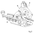
- a drive unit 1 is in a passenger car 2 of the sports car category - dynamic, attractive appearance and sophisticated performance - built-in from which only a unit carrier 3 of the drive unit 1 and a rear axle 4 with Wheels 5 and 6 are shown.
- the drive unit 3 comprises one Internal combustion engine 7 and a housing assembly 8, which is used to receive a clutch 9 a transmission 10 and a differential 11 is formed.
- the opposite Internal combustion engine 7 having cylinder rows 12, 13 with an approximately in one Longitudinal center plane B-B of the passenger car 2 extending crankshaft 14 - only shown schematically - seen in the direction of travel C in front of the rear axle 4 - Mid-motor arrangement - and it is directly blocked with the housing assembly 8.
- the drive unit 3 is mediated by a front Unit bearing 15 and rear unit bearings 16, 17 on the unit carrier 3, the is designed in the manner of a drive unit surrounding an enveloping body, attached.
- the housing assembly 8 with third bearings 23 for the differential 11th Mistake is a container area 24 for one Integrated dry sump lubrication.
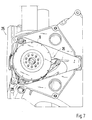
- the side 25 is, for example, from a Light metal alloy existing housing assembly 8 with a receiving space 26 provided that the clutch 9 together with a console 27 for a Release device 28 essentially completely accommodates - Fig. 7 -.
- the Receiving space 26 has a trapezoidal shape that extends above clutch 9 lying container area 24 tapers.
- Between a back wall 33 and the side walls 29, 30 are offset in height approximately horizontally extending reinforcing ribs 34, 35 and 36, 37 are provided.
- the clutch 9 is connected to the crankshaft 14 by means of a flywheel 38 Internal combustion engine 7 connected, which is not shown.
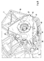
- the console is 27 with the help of screws 39 on the housing structure 18 of the internal combustion engine 7 attached, on a side 40 facing the housing assembly 8.
- the console 27 comprises a base plate 41 which has the shape of an equilateral triangle having. At the top of the triangle there are three more rotationally symmetrical ones Coupling elements 42 of coupling 9 encompassing fastening pins 43, 44 and 45 attached, which are supported on the housing structure 18 of the internal combustion engine 7 - Fig. 9 -.
- the housing assembly 8 comprises a first housing part 46 and a second housing part 47.
- the first housing part 46 In the first housing part 46, the first bearings 19 for the input shaft 21 and the third bearings 23 are provided for the differential 11.
- the second housing part 47 and the first housing part 46 form the bearings 20 for the Output shaft 22 in such a way that the bearings 20 by bearing halves 48, 49 of the first housing part 46 and the second housing part 47 are shown.
- This Housing part 47 is on a side 50 remote from internal combustion engine 7 at least one support bracket 51 for the attachment of the drive unit 1 a cross member 52 extending between the unit bearings 16, 17 is provided.
- the bearing halves 47, 48 are on both sides of a relatively upright parting plane 53, along which the first housing part 46 and the second housing part 47 below Mediation of screws 54 are interconnected.
- 3 shows that the container area 24, the receiving space 26 and a differential space 55 through a wall structure 56 are separated from each other.
- This wall structure 56 connects the Rear wall 33 with a front wall 57 and a bottom wall 58, so that a stiffer Frame assembly for the housing assembly 8 is created.
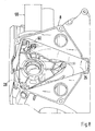
- FIG. 8 shows how a starting device 59 for the internal combustion engine 1 in FIG Housing assembly 8 is used. Thereafter, the starter device 59 also penetrates a starter pinion 60, the side wall 29 of the housing assembly 8, wherein the starter pinion 60 cooperates with a not shown ring gear element of the clutch 9.
Landscapes
- Engineering & Computer Science (AREA)
- Mechanical Engineering (AREA)
- General Engineering & Computer Science (AREA)
- Chemical & Material Sciences (AREA)
- Combustion & Propulsion (AREA)
- Transportation (AREA)
- Arrangement Of Transmissions (AREA)
- General Details Of Gearings (AREA)
- Hybrid Electric Vehicles (AREA)
Abstract
Description
- Fig. 1
- eine Ansicht von oben auf ein erfindungsgemäße Antriebsaggregat, eingebaut in einen teilweise dargestellten Personenkraftwagen,
- Fig. 2
- eine Schrägansicht auf das Antriebsaggregat von hinten rechts des Personenkraftwagens,
- Fig. 3
- einen Schnitt nach der Linie IV-IV der Fig. 1 in größerem Maßstab,
- Fig. 4
- eine Ansicht in Pfeilrichtung A der Fig. 1 in größerem Maßstab,
- Fig. 5
- eine Schrägansicht von hinten links auf eine Gehäusebaueinheit des Antriebsaggregats,
- Fig. 6
- eine Schrägansicht teilweise im Schnitt von vorne links auf die Gehäusebaueinheit,
- Fig. 7
- einen Schnitt etwa nach der Linie Vll-Vll der Fig.1,
- Fig. 8
- eine Ansicht entsprechend Fig. 7,
- Fig. 9
- eine Schrägansicht auf die Rückseite der Brennkraftmaschine von hinten links.
Claims (12)
- Antriebsaggregat für ein Kraftfahrzeug, insbesondere einen Personenkraftwagen der Sportwagengattung, das eine Brennkraftmaschine und eine Gehäusebaueinheit vorzugsweise zur Aufnahme einer Kupplung, eines Getriebes und eines Differentials umfasst, dadurch gekennzeichnet, dass die die Kupplung (9) aufnehmende und mit der Brennkraftmaschine (7) verbundene Gehäusebaueinheit (8) des Antriebsaggregats (1) erste Lager (19) und zweite Lager (29) für eine Eingangswelle (21) sowie eine Ausgangswelle (22) des Getriebes (11) und dritte Lager (23) für das Differential (11) aufweist, wobei in die Gehäusebaueinheit (8) ein Behälterbereich (24) für eine Trockensumpfschmierung der Brennkraftmaschine (7) integriert ist.
- Antriebsaggregat nach Anspruch 1, dadurch gekennzeichnet, dass die Gehäusebaueinheit (8) und eine Gehäusestruktur (18) der Brennkraftmaschine (7) als getrennte Bauteile an einer Verbindungsebene (Vb) zusammengesetzt sind.
- Antriebsaggregat nach Anspruch 1, dadurch gekennzeichnet, dass die Eingangswelle (21) und Ausgangswelle (22) quer zu einer Längsmittelebene (B-B) des Personenkraftwagen (1) angeordnet sind.
- Antriebsaggregat nach Anspruch 1, dadurch gekennzeichnet, dass die Gehäusebaueinheit (8) auf der der Brennkraftmaschine (7) zugekehrten Seite (25) eine Aufnahmeraum (26) für die Kupplung (9) besitzt.
- Antriebsaggregat nach Anspruch 4, dadurch gekennzeichnet, dass die Kupplung (9) unter Vermittlung einer Schwungscheibe (38) an einer Kurbelwelle (14) der Brennkraftmaschine (7) in Lage gehalten wird.
- Antriebsaggregat nach Anspruch 1, dadurch gekennzeichnet, die Gehäusebaueinheit (8) ein erstes Gehäuseteil (46) für die ersten Lager (19) der Eingangswelle (21) und die dritten Lager (23) des Differentials (11) umfasst, wobei ein zweites Gehäuseteil (47) zusammen mit dem ersten Gehäuseteil (46) die zweiten Lager (20) für die Ausgangswelle (22) bilden.
- Antriebsaggregat nach Anspruch 6, dadurch gekennzeichnet, dass die zweiten Lager (20) durch Lagerhälften (48,49) des ersten Gehäuseteils (46) und des zweiten Gehäuseteils (47) gebildet werden.
- Antriebsaggregat nach Anspruch 7, dadurch gekennzeichnet, dass die Lagerhälften (48,49) beiderseits einer Trennebene (53) vorgesehen sind, an der das erste Gehäuseteil (46) und das zweite Gehäuseteil (47) zusammengesetzt sind.
- Antriebsaggregat nach Anspruch I, dadurch gekennzeichnet, dass die Trennebene (53) zwischen dem ersten Gehäuseteil (46) und dem zweiten Gehäuseteil (47) relativ aufrecht verläuft.
- Antriebsaggregat nach einem oder mehreren der vorangehenden Ansprüche, dadurch gekennzeichnet, dass die Gehäusebaueinheit (8) zur Aufnahme einer Anlassvorrichtung (59) der Brennkraftmaschine (7) ausgebildet ist, die mit der Kupplung (9) zusammenarbeitet.
- Antriebsaggregat nach Anspruch 10, dadurch gekennzeichnet, dass die Anlassvorrichtung (59) mit einem Anlassritzel (60) durch eine Seitenwand (29) der Gehäusebaueinheit (8) hindurchgeführt ist, wobei das Anlassritzel (60) mit einem Zahnkranzelement der Kupplung (9) zusammenarbeitet.
- Antriebsaggregat nach einem oder mehreren der vorangehenden Ansprüche, dadurch gekennzeichnet, dass die Gehäusebaueinheit (8) auf einer von der Brennkraftmaschine abgekehrten Seite (50) mit wenigstens einer Tragkonsolen (51) für die Lagerung des Antriebsaggregats (1) versehen ist.
Applications Claiming Priority (2)
| Application Number | Priority Date | Filing Date | Title |
|---|---|---|---|
| DE10308757 | 2003-02-28 | ||
| DE10308757A DE10308757B4 (de) | 2003-02-28 | 2003-02-28 | Antriebsaggregat für ein Kraftfahrzeug |
Publications (2)
| Publication Number | Publication Date |
|---|---|
| EP1452380A1 true EP1452380A1 (de) | 2004-09-01 |
| EP1452380B1 EP1452380B1 (de) | 2009-04-15 |
Family
ID=32748109
Family Applications (1)
| Application Number | Title | Priority Date | Filing Date |
|---|---|---|---|
| EP03027964A Expired - Lifetime EP1452380B1 (de) | 2003-02-28 | 2003-12-05 | Antriebsaggregat für ein Kraftfahrzeug |
Country Status (4)
| Country | Link |
|---|---|
| US (1) | US20040168543A1 (de) |
| EP (1) | EP1452380B1 (de) |
| JP (1) | JP2004262442A (de) |
| DE (2) | DE10308757B4 (de) |
Families Citing this family (1)
| Publication number | Priority date | Publication date | Assignee | Title |
|---|---|---|---|---|
| US10935124B2 (en) | 2018-05-23 | 2021-03-02 | Dana Automotive Systems Group, Llc | Carrier assembly with offset trunnion ribs |
Citations (7)
| Publication number | Priority date | Publication date | Assignee | Title |
|---|---|---|---|---|
| GB378489A (en) | 1931-04-02 | 1932-08-08 | Birger Ljungstroem | Improvements in or relating to power transmission for motor vehicles |
| GB1006701A (en) * | 1963-09-13 | 1965-10-06 | Ford Motor Co | Motor vehicle transmission unit |
| DE2140377A1 (de) * | 1971-08-12 | 1973-02-15 | Porsche Kg | Schmiermittelkreislauf von brennkraftmaschinen mit trockensumpfschmierung |
| EP0183051A1 (de) | 1984-10-26 | 1986-06-04 | Nissan Motor Co., Ltd. | Kraftübertragungssystem für Kraftfahrzeuge |
| US4920825A (en) | 1987-03-06 | 1990-05-01 | Honda Giken Kabushiki Kaisha | Vehicle engine |
| GB2291117A (en) * | 1994-06-24 | 1996-01-17 | Ford Motor Co | Two-stroke engine installation |
| DE10029844A1 (de) * | 2000-06-16 | 2002-01-03 | Porsche Ag | Brennkraftmaschine, insbesondere für Motorräder |
Family Cites Families (16)
| Publication number | Priority date | Publication date | Assignee | Title |
|---|---|---|---|---|
| US1473194A (en) * | 1920-07-24 | 1923-11-06 | John Keller | Motor car |
| US1989446A (en) * | 1932-05-07 | 1935-01-29 | Ganz Joseph | Driving block arrangement for motor vehicles |
| US2448345A (en) * | 1944-12-20 | 1948-08-31 | Charles N Aronson | Drive for automobiles and the like |
| US3204717A (en) * | 1961-11-30 | 1965-09-07 | Ford Motor Co | Vehicle power plant and wheel suspension system |
| US3302740A (en) * | 1963-10-15 | 1967-02-07 | Fiat Spa | Front wheel drive aggregate for motor vehicles |
| US3373833A (en) * | 1964-07-31 | 1968-03-19 | Honda Gijutsu Kenkyusho Kk | Compact motor car construction |
| US3555930A (en) * | 1969-02-26 | 1971-01-19 | James G Boyd | Transmission unit |
| DE2139340A1 (de) * | 1971-08-06 | 1973-02-15 | Porsche Kg | Antriebseinheit fuer fahrzeuge, insbesondere fuer kraftfahrzeuge |
| DE2825177A1 (de) * | 1978-06-08 | 1979-12-13 | Hatz Motoren | Brennkraftmaschine |
| JPS6192335A (ja) * | 1984-10-09 | 1986-05-10 | Honda Motor Co Ltd | 車両用変速機 |
| US5024287A (en) * | 1987-03-31 | 1991-06-18 | Yamaha Hatsudiki Kabushiki Kaisha | Engine unit for vehicle |
| JPH026222A (ja) * | 1988-06-24 | 1990-01-10 | Honda Motor Co Ltd | 車両の駆動装置 |
| US5257674A (en) * | 1988-11-14 | 1993-11-02 | Yamaha Hatsudoki Kabushiki Kaisha | Engine construction for vehicle |
| US5186078A (en) * | 1991-03-19 | 1993-02-16 | Mazda Motor Corporation | Engine unit |
| DE4307999A1 (de) * | 1993-03-13 | 1994-09-15 | Porsche Ag | Kraftfahrzeug |
| DE10202956B4 (de) * | 2002-01-26 | 2006-09-07 | Dr.Ing.H.C. F. Porsche Ag | Tragstruktur für ein Antriebsaggregat eines Kraftfahrzeugs |
-
2003
- 2003-02-28 DE DE10308757A patent/DE10308757B4/de not_active Expired - Fee Related
- 2003-12-05 DE DE50311415T patent/DE50311415D1/de not_active Expired - Lifetime
- 2003-12-05 EP EP03027964A patent/EP1452380B1/de not_active Expired - Lifetime
-
2004
- 2004-02-10 US US10/774,408 patent/US20040168543A1/en not_active Abandoned
- 2004-02-25 JP JP2004049947A patent/JP2004262442A/ja not_active Withdrawn
Patent Citations (7)
| Publication number | Priority date | Publication date | Assignee | Title |
|---|---|---|---|---|
| GB378489A (en) | 1931-04-02 | 1932-08-08 | Birger Ljungstroem | Improvements in or relating to power transmission for motor vehicles |
| GB1006701A (en) * | 1963-09-13 | 1965-10-06 | Ford Motor Co | Motor vehicle transmission unit |
| DE2140377A1 (de) * | 1971-08-12 | 1973-02-15 | Porsche Kg | Schmiermittelkreislauf von brennkraftmaschinen mit trockensumpfschmierung |
| EP0183051A1 (de) | 1984-10-26 | 1986-06-04 | Nissan Motor Co., Ltd. | Kraftübertragungssystem für Kraftfahrzeuge |
| US4920825A (en) | 1987-03-06 | 1990-05-01 | Honda Giken Kabushiki Kaisha | Vehicle engine |
| GB2291117A (en) * | 1994-06-24 | 1996-01-17 | Ford Motor Co | Two-stroke engine installation |
| DE10029844A1 (de) * | 2000-06-16 | 2002-01-03 | Porsche Ag | Brennkraftmaschine, insbesondere für Motorräder |
Also Published As
| Publication number | Publication date |
|---|---|
| DE50311415D1 (de) | 2009-05-28 |
| DE10308757B4 (de) | 2007-02-01 |
| JP2004262442A (ja) | 2004-09-24 |
| EP1452380B1 (de) | 2009-04-15 |
| DE10308757A1 (de) | 2004-09-16 |
| US20040168543A1 (en) | 2004-09-02 |
Similar Documents
| Publication | Publication Date | Title |
|---|---|---|
| DE3807183C2 (de) | ||
| DE2838669C2 (de) | Schmiervorrichtung für einen Achsantrieb | |
| DE2805901C2 (de) | Gehäuse für eine Fahrzeug-Kraftübertragungseinheit | |
| DE2832616C2 (de) | Triebwerkeinheit für ein Kraftfahrzeug | |
| DE3801715C2 (de) | ||
| DE69706909T2 (de) | Zweiteiliges Gehäuse für ein Verbundgetriebe | |
| DE3920638C2 (de) | Antriebssystem für ein Fahrzeug | |
| DE10250733B4 (de) | Getriebe mit einer Lagereinheit | |
| DE2805900A1 (de) | Kraftuebertragungseinheit fuer ein kraftfahrzeug | |
| EP0838577B1 (de) | Ölversorgungssystem für einen Kraftfahrzeugmotor | |
| DE102015118003A1 (de) | Fahrzeugverteilergetriebebaugruppe mit einteiliger Drehmomentübertragungskomponente, die einen Kettenradabschnitt und einen Abtriebsflanschabschnitt aufweist | |
| DE102009025453B4 (de) | Ausgleichswellenmodul | |
| DE102019201585A1 (de) | Antriebsstrang für ein Fahrzeug, insbesondere für ein Kraftfahrzeug | |
| EP1148271A2 (de) | Achsgetriebe für ein Kraftfahrzeug | |
| DE4143102A1 (de) | Kraftuebertragungsteil fuer ein kraftfahrzeug | |
| DE3888119T2 (de) | Antriebssystem für Kraftfahrzeuge. | |
| EP0864779B1 (de) | Ausgleichsgetriebe,insbesondere für den Achsantrieb eines Kraftfahrzeugs | |
| DE10308757B4 (de) | Antriebsaggregat für ein Kraftfahrzeug | |
| DE3841818C2 (de) | Getriebeeinheit mit Vorderrad-Differential für ein Kraftfahrzeug | |
| DE102008063315A1 (de) | Massenausgleichseinheit | |
| EP0485442B1 (de) | Getriebeeinheit für ein zwei triebachsen aufweisendes kraftfahrzeug | |
| DE202006020617U1 (de) | Vorrichtung zum Kräfte- und/oder Momentenausgleich für Brennkraftmaschinen | |
| DE3119362C2 (de) | Vierzylinder-Brennkraftmaschine mit einem Massenausgleich zweiter Ordnung | |
| DE112024000622T5 (de) | Kompaktes koaxiales untersetzungsgetriebe | |
| DE102005001863A1 (de) | Mehrzylindrige Brennkraftmaschine |
Legal Events
| Date | Code | Title | Description |
|---|---|---|---|
| PUAI | Public reference made under article 153(3) epc to a published international application that has entered the european phase |
Free format text: ORIGINAL CODE: 0009012 |
|
| AK | Designated contracting states |
Kind code of ref document: A1 Designated state(s): AT BE BG CH CY CZ DE DK EE ES FI FR GB GR HU IE IT LI LU MC NL PT RO SE SI SK TR |
|
| AX | Request for extension of the european patent |
Extension state: AL LT LV MK |
|
| 17P | Request for examination filed |
Effective date: 20050301 |
|
| AKX | Designation fees paid |
Designated state(s): DE FR GB IT |
|
| RBV | Designated contracting states (corrected) |
Designated state(s): DE FR GB IT |
|
| 17Q | First examination report despatched |
Effective date: 20061012 |
|
| RIN1 | Information on inventor provided before grant (corrected) |
Inventor name: ARMBRUSTER, REINER Inventor name: SCHOLZ, ANDRE Inventor name: BRAUN, WOLFGANG Inventor name: HUELSEMANN, ULRICH |
|
| RIN1 | Information on inventor provided before grant (corrected) |
Inventor name: HUELSEMANN, ULRICH |
|
| RIN1 | Information on inventor provided before grant (corrected) |
Inventor name: HUELSEMANN, ULRICH |
|
| 17Q | First examination report despatched |
Effective date: 20061012 |
|
| RAP1 | Party data changed (applicant data changed or rights of an application transferred) |
Owner name: DR. ING. H.C. F. PORSCHE AKTIENGESELLSCHAFT |
|
| RAP1 | Party data changed (applicant data changed or rights of an application transferred) |
Owner name: DR. ING. H.C. F. PORSCHE AKTIENGESELLSCHAFT |
|
| GRAP | Despatch of communication of intention to grant a patent |
Free format text: ORIGINAL CODE: EPIDOSNIGR1 |
|
| GRAJ | Information related to disapproval of communication of intention to grant by the applicant or resumption of examination proceedings by the epo deleted |
Free format text: ORIGINAL CODE: EPIDOSDIGR1 |
|
| GRAP | Despatch of communication of intention to grant a patent |
Free format text: ORIGINAL CODE: EPIDOSNIGR1 |
|
| GRAS | Grant fee paid |
Free format text: ORIGINAL CODE: EPIDOSNIGR3 |
|
| GRAA | (expected) grant |
Free format text: ORIGINAL CODE: 0009210 |
|
| AK | Designated contracting states |
Kind code of ref document: B1 Designated state(s): DE FR GB IT |
|
| REG | Reference to a national code |
Ref country code: GB Ref legal event code: FG4D Free format text: NOT ENGLISH |
|
| REF | Corresponds to: |
Ref document number: 50311415 Country of ref document: DE Date of ref document: 20090528 Kind code of ref document: P |
|
| PLBE | No opposition filed within time limit |
Free format text: ORIGINAL CODE: 0009261 |
|
| STAA | Information on the status of an ep patent application or granted ep patent |
Free format text: STATUS: NO OPPOSITION FILED WITHIN TIME LIMIT |
|
| 26N | No opposition filed |
Effective date: 20100118 |
|
| PGFP | Annual fee paid to national office [announced via postgrant information from national office to epo] |
Ref country code: FR Payment date: 20110104 Year of fee payment: 8 |
|
| REG | Reference to a national code |
Ref country code: FR Ref legal event code: TP |
|
| PGFP | Annual fee paid to national office [announced via postgrant information from national office to epo] |
Ref country code: GB Payment date: 20101221 Year of fee payment: 8 |
|
| REG | Reference to a national code |
Ref country code: GB Ref legal event code: 732E Free format text: REGISTERED BETWEEN 20110310 AND 20110316 |
|
| REG | Reference to a national code |
Ref country code: GB Ref legal event code: 732E Free format text: REGISTERED BETWEEN 20110331 AND 20110406 |
|
| PGFP | Annual fee paid to national office [announced via postgrant information from national office to epo] |
Ref country code: DE Payment date: 20101115 Year of fee payment: 8 Ref country code: IT Payment date: 20101223 Year of fee payment: 8 |
|
| GBPC | Gb: european patent ceased through non-payment of renewal fee |
Effective date: 20111205 |
|
| REG | Reference to a national code |
Ref country code: FR Ref legal event code: ST Effective date: 20120831 |
|
| REG | Reference to a national code |
Ref country code: DE Ref legal event code: R119 Ref document number: 50311415 Country of ref document: DE Effective date: 20120703 |
|
| PG25 | Lapsed in a contracting state [announced via postgrant information from national office to epo] |
Ref country code: GB Free format text: LAPSE BECAUSE OF NON-PAYMENT OF DUE FEES Effective date: 20111205 Ref country code: DE Free format text: LAPSE BECAUSE OF NON-PAYMENT OF DUE FEES Effective date: 20120703 |
|
| PG25 | Lapsed in a contracting state [announced via postgrant information from national office to epo] |
Ref country code: IT Free format text: LAPSE BECAUSE OF NON-PAYMENT OF DUE FEES Effective date: 20111205 |
|
| PG25 | Lapsed in a contracting state [announced via postgrant information from national office to epo] |
Ref country code: FR Free format text: LAPSE BECAUSE OF NON-PAYMENT OF DUE FEES Effective date: 20120102 |