EP1450052B1 - Beschlag - Google Patents
Beschlag Download PDFInfo
- Publication number
- EP1450052B1 EP1450052B1 EP04001050A EP04001050A EP1450052B1 EP 1450052 B1 EP1450052 B1 EP 1450052B1 EP 04001050 A EP04001050 A EP 04001050A EP 04001050 A EP04001050 A EP 04001050A EP 1450052 B1 EP1450052 B1 EP 1450052B1
- Authority
- EP
- European Patent Office
- Prior art keywords
- housing
- tightening bolt
- head
- fitting
- clamping member
- Prior art date
- Legal status (The legal status is an assumption and is not a legal conclusion. Google has not performed a legal analysis and makes no representation as to the accuracy of the status listed.)
- Expired - Lifetime
Links
- 238000001746 injection moulding Methods 0.000 abstract description 3
- 238000000465 moulding Methods 0.000 abstract 1
- 101100390736 Danio rerio fign gene Proteins 0.000 description 5
- 101100390738 Mus musculus Fign gene Proteins 0.000 description 5
- 238000004519 manufacturing process Methods 0.000 description 2
- 230000006835 compression Effects 0.000 description 1
- 238000007906 compression Methods 0.000 description 1
- 238000006073 displacement reaction Methods 0.000 description 1
- 230000003993 interaction Effects 0.000 description 1
- 239000000463 material Substances 0.000 description 1
- 239000007787 solid Substances 0.000 description 1
Images




Classifications
-
- F—MECHANICAL ENGINEERING; LIGHTING; HEATING; WEAPONS; BLASTING
- F16—ENGINEERING ELEMENTS AND UNITS; GENERAL MEASURES FOR PRODUCING AND MAINTAINING EFFECTIVE FUNCTIONING OF MACHINES OR INSTALLATIONS; THERMAL INSULATION IN GENERAL
- F16B—DEVICES FOR FASTENING OR SECURING CONSTRUCTIONAL ELEMENTS OR MACHINE PARTS TOGETHER, e.g. NAILS, BOLTS, CIRCLIPS, CLAMPS, CLIPS OR WEDGES; JOINTS OR JOINTING
- F16B12/00—Jointing of furniture or the like, e.g. hidden from exterior
- F16B12/10—Jointing of furniture or the like, e.g. hidden from exterior using pegs, bolts, tenons, clamps, clips, or the like
- F16B12/12—Jointing of furniture or the like, e.g. hidden from exterior using pegs, bolts, tenons, clamps, clips, or the like for non-metal furniture parts, e.g. made of wood, of plastics
- F16B12/20—Jointing of furniture or the like, e.g. hidden from exterior using pegs, bolts, tenons, clamps, clips, or the like for non-metal furniture parts, e.g. made of wood, of plastics using clamps, clips, wedges, sliding bolts, or the like
- F16B12/2009—Jointing of furniture or the like, e.g. hidden from exterior using pegs, bolts, tenons, clamps, clips, or the like for non-metal furniture parts, e.g. made of wood, of plastics using clamps, clips, wedges, sliding bolts, or the like actuated by rotary motion
- F16B12/2027—Jointing of furniture or the like, e.g. hidden from exterior using pegs, bolts, tenons, clamps, clips, or the like for non-metal furniture parts, e.g. made of wood, of plastics using clamps, clips, wedges, sliding bolts, or the like actuated by rotary motion with rotating excenters or wedges
- F16B12/2036—Jointing of furniture or the like, e.g. hidden from exterior using pegs, bolts, tenons, clamps, clips, or the like for non-metal furniture parts, e.g. made of wood, of plastics using clamps, clips, wedges, sliding bolts, or the like actuated by rotary motion with rotating excenters or wedges with rotating excenters or wedges acting on a head of a pin or screw
-
- F—MECHANICAL ENGINEERING; LIGHTING; HEATING; WEAPONS; BLASTING
- F16—ENGINEERING ELEMENTS AND UNITS; GENERAL MEASURES FOR PRODUCING AND MAINTAINING EFFECTIVE FUNCTIONING OF MACHINES OR INSTALLATIONS; THERMAL INSULATION IN GENERAL
- F16B—DEVICES FOR FASTENING OR SECURING CONSTRUCTIONAL ELEMENTS OR MACHINE PARTS TOGETHER, e.g. NAILS, BOLTS, CIRCLIPS, CLAMPS, CLIPS OR WEDGES; JOINTS OR JOINTING
- F16B12/00—Jointing of furniture or the like, e.g. hidden from exterior
- F16B12/10—Jointing of furniture or the like, e.g. hidden from exterior using pegs, bolts, tenons, clamps, clips, or the like
- F16B12/12—Jointing of furniture or the like, e.g. hidden from exterior using pegs, bolts, tenons, clamps, clips, or the like for non-metal furniture parts, e.g. made of wood, of plastics
- F16B12/20—Jointing of furniture or the like, e.g. hidden from exterior using pegs, bolts, tenons, clamps, clips, or the like for non-metal furniture parts, e.g. made of wood, of plastics using clamps, clips, wedges, sliding bolts, or the like
- F16B12/2009—Jointing of furniture or the like, e.g. hidden from exterior using pegs, bolts, tenons, clamps, clips, or the like for non-metal furniture parts, e.g. made of wood, of plastics using clamps, clips, wedges, sliding bolts, or the like actuated by rotary motion
-
- F—MECHANICAL ENGINEERING; LIGHTING; HEATING; WEAPONS; BLASTING
- F16—ENGINEERING ELEMENTS AND UNITS; GENERAL MEASURES FOR PRODUCING AND MAINTAINING EFFECTIVE FUNCTIONING OF MACHINES OR INSTALLATIONS; THERMAL INSULATION IN GENERAL
- F16B—DEVICES FOR FASTENING OR SECURING CONSTRUCTIONAL ELEMENTS OR MACHINE PARTS TOGETHER, e.g. NAILS, BOLTS, CIRCLIPS, CLAMPS, CLIPS OR WEDGES; JOINTS OR JOINTING
- F16B2200/00—Constructional details of connections not covered for in other groups of this subclass
- F16B2200/40—Clamping arrangements where clamping parts are received in recesses of elements to be connected
-
- F—MECHANICAL ENGINEERING; LIGHTING; HEATING; WEAPONS; BLASTING
- F16—ENGINEERING ELEMENTS AND UNITS; GENERAL MEASURES FOR PRODUCING AND MAINTAINING EFFECTIVE FUNCTIONING OF MACHINES OR INSTALLATIONS; THERMAL INSULATION IN GENERAL
- F16B—DEVICES FOR FASTENING OR SECURING CONSTRUCTIONAL ELEMENTS OR MACHINE PARTS TOGETHER, e.g. NAILS, BOLTS, CIRCLIPS, CLAMPS, CLIPS OR WEDGES; JOINTS OR JOINTING
- F16B2200/00—Constructional details of connections not covered for in other groups of this subclass
- F16B2200/67—Rigid angle couplings
-
- Y—GENERAL TAGGING OF NEW TECHNOLOGICAL DEVELOPMENTS; GENERAL TAGGING OF CROSS-SECTIONAL TECHNOLOGIES SPANNING OVER SEVERAL SECTIONS OF THE IPC; TECHNICAL SUBJECTS COVERED BY FORMER USPC CROSS-REFERENCE ART COLLECTIONS [XRACs] AND DIGESTS
- Y10—TECHNICAL SUBJECTS COVERED BY FORMER USPC
- Y10S—TECHNICAL SUBJECTS COVERED BY FORMER USPC CROSS-REFERENCE ART COLLECTIONS [XRACs] AND DIGESTS
- Y10S403/00—Joints and connections
- Y10S403/12—Furniture type having a rotatable fastener or fastening element that tightens connection
-
- Y—GENERAL TAGGING OF NEW TECHNOLOGICAL DEVELOPMENTS; GENERAL TAGGING OF CROSS-SECTIONAL TECHNOLOGIES SPANNING OVER SEVERAL SECTIONS OF THE IPC; TECHNICAL SUBJECTS COVERED BY FORMER USPC CROSS-REFERENCE ART COLLECTIONS [XRACs] AND DIGESTS
- Y10—TECHNICAL SUBJECTS COVERED BY FORMER USPC
- Y10T—TECHNICAL SUBJECTS COVERED BY FORMER US CLASSIFICATION
- Y10T403/00—Joints and connections
- Y10T403/46—Rod end to transverse side of member
- Y10T403/4602—Corner joint
Definitions
- the invention relates to a fitting for releasably connecting two plates, in particular furniture panels, with a rotatable in a housing from a release in a locking position clamping part which receives the head of an associated tightening bolt as it is known from US 6 142 700 A.
- the housing consists of an upper and a lower part, which are connected to one another in a lockable manner, the two parts and the clamping part arranged between them being manufactured in one operation via predetermined breaking points. This is, if you, for example, the Fittings produced by injection molding, only a single tool required.
- the clamping part In order to assemble the parts easily after manufacture, the clamping part is above the lower housing part and the upper housing part above the clamping part, the three parts are each arranged centrally to each other prior to assembly. It is then only necessary to press the upper housing part on the lower part. The clamping part is pressed by the upper housing part with in the lower part, whereupon the locking connection between the two housing parts takes place.
- the pull stud is made in one operation with the other parts and is also connected via a predetermined breaking point, this results in a further improvement.
- the head of the tightening bolt is separated before the latching connection of the housing parts and inserted into the clamping part, from which then protrudes designed as a shaft free end of the tightening bolt.
- a sleeve for guiding the tightening bolt is arranged on the housing.
- the pull stud itself is provided at its head opposite the end of his shaft with swing barbs, which are provided with provided at the free end of the sleeve bevels or with a frusto-conical sleeve end spreading interact.
- the fully assembled fitting is then inserted with the shaft of the tightening bolt in the bore of one and the housing in the bore of another plate. Then, when the clamping member is rotated to tighten the tightening bolt accordingly, the swinging barbs run on the free end of the sleeve, thereby spreading in the bore of the corresponding plate and are thus determined in this.
- the clamping part In order to be able to separate the plates from each other again in a simple manner, in a fitting with a tightening bolt whose shaft is offset from the head in diameter, the clamping part has two approximately opposite clamping curves. In this case, the head part of the tightening bolt directed towards the shaft bears against the tightening curve. The free head end, however, is located on an ejection curve. Now, if the clamping part is rotated counter to the clamping direction, carried out by the Auaracekurve a directed into the bore backward displacement of the shank of the tightening bolt. The barbs are swung back through the bore walls in their original position on the shaft, so that then the fitting can be removed with the pull stud from the bore.
- the fitting according to Fig. 1 consists of an upper part 1, a lower part 2, and a clamping part 3. These three parts are arranged centrally one above the other and connected by not recognizable from the drawing predetermined breaking points. As soon as pressure is exerted on the upper housing part 1, the clamping part 3 pushes into and the upper housing part 1 onto the lower housing part 2 until the lugs 4 of the upper part 1 engage in the recesses 5 of the lower part 2, as shown in FIG.
- the tightening bolt 6 is screwed with its shaft 7 in the bore 8 of a plate 9, up to the annular flange 10.
- the housing 1.2 is then inserted into the bore 11 of the second plate 12, whereupon the two Plates 9 and 12 are compressed.
- the head 13 of the tightening bolt 6 is inserted through the opening 14 of the housing 1.2 in the clamping part 3, whereupon then tightened by appropriate rotation of the clamping part 3 of the tightening bolt 6 and thus the plates 9 and 12 are firmly connected.
- FIG. 4 a further embodiment of the fitting according to the invention is shown.
- the upper housing part 14, the clamping part 16 and the lower housing part 17 are centrally superimposed and are connected to each other by predetermined breaking points, not shown.
- a pull stud 18 is still provided, which is connected via a predetermined breaking point 36 with the clamping part 16.
- To mount the parts of the pull stud 18 is released from the clamping part 16 and, as shown in FIG. 5, inserted into this. Subsequently, in turn, the compression of the upper housing part 14 and the lower housing part 17 takes place until the ready-to-use fitting 15 according to FIG. 6 results.
- the locking takes place here again by lugs 19 and locking recesses 20th
- the pull stud 18 has a shaft 21 and a head 22. At the free end, two barbs 23,24 are pivotally provided.
- the housing 14, 17 is provided with a sleeve 25 which has at its free end two opposing ramps 26 for the barbs 23, 24.
Landscapes
- Engineering & Computer Science (AREA)
- General Engineering & Computer Science (AREA)
- Mechanical Engineering (AREA)
- Connection Of Plates (AREA)
- Furniture Connections (AREA)
- Mechanical Coupling Of Light Guides (AREA)
- Clamps And Clips (AREA)
- Coupling Device And Connection With Printed Circuit (AREA)
- Non-Reversible Transmitting Devices (AREA)
- Massaging Devices (AREA)
- Infusion, Injection, And Reservoir Apparatuses (AREA)
- Insertion Pins And Rivets (AREA)
Description
- Die Erfindung bezieht sich auf einen Beschlag zur lösbaren Verbindung zweier Platten, insbesondere Möbelplatten, mit einem in einem Gehäuse aus einer Freigabe in eine Sperrstellung drehbaren Spannteil, welches den Kopf eines zugehörigen Anzugsbolzens aufnimmt wie es aus der US 6 142 700 A bekannt ist. Um die Herstellung der Teile und ihre Montage zu vereinfachen, besteht erfindungsgemäß das Gehäuse aus einem Ober- und einem Unterteil, welche rastbar miteinander verbindbar sind, wobei die beiden Teile und das zwischen ihnen angeordnete Spannteil in einem Arbeitsgang über Sollbruchstellen zusammenhängend gefertigt sind. Damit ist, wenn man beispielsweise den Beschlag im Spritzgussverfahren herstellt, nur noch ein einziges Werkzeug erforderlich.
- Um die Teile nach der Herstellung leicht zusammensetzen zu können, befindet sich vor der Montage das Spannteil über dem Gehäuseunterteil und das Gehäuseoberteil über dem Spannteil, wobei alle drei Teile jeweils zentrisch zueinander angeordnet sind. Es ist dann nur noch erforderlich, das Gehäuseoberteil auf das Unterteil zu pressen. Dabei wird das Spannteil durch das Gehäuseoberteil mit in das Unterteil gedrückt, worauf dann die Rastverbindung zwischen den beiden Gehäuseteilen erfolgt.
- Wenn zusätzlich noch der Anzugsbolzen in einem Arbeitsgang mit den anderen Teilen gefertigt wird und ebenfalls über eine Sollbruchstelle verbunden ist, ergibt sich hierdurch noch eine weitere Verbesserung. In diesem Fall wird der Kopf des Anzugsbolzens vor der Rastverbindung der Gehäuseteile abgetrennt und in das Spannteil eingesetzt, aus welchem das als Schaft ausgebildete freie Ende des Anzugsbolzens dann herausragt.
- Bei einer bevorzugten Ausführungsform ist am Gehäuse eine Hülse zur Führung des Anzugsbolzens angeordnet. Der Anzugsbolzen selbst ist an seinem dem Kopf entgegengesetzten Ende seines Schaftes mit ausschwenkbaren Widerhaken versehen, welche mit am freien Ende der Hülse vorgesehenen Auflaufschrägen oder mit einem kegelstumpfförmig ausgebildeten Hülsenende sich spreizend zusammenwirken. Der fertig montierte Beschlag wird dann mit dem Schaft des Anzugsbolzens in die Bohrung der einen und das Gehäuse in die Bohrung einer anderen Platte eingesetzt. Wenn dann das Spannteil zum Anziehen des Anzugsbolzens entsprechend gedreht wird, laufen die ausschwenkbaren Widerhaken am freien Ende der Hülse auf, spreizen sich dabei in der Bohrung der entsprechenden Platte und werden dadurch in dieser festgelegt.
- Um die Platten auf einfache Weise wieder voneinander trennen zu können, weist bei einem Beschlag mit einem Anzugsbolzen, dessen Schaft gegenüber dem Kopf im Durchmesser abgesetzt ist, das Spannteil zwei sich etwa gegenüberliegende Spannkurven auf. Dabei liegt das zum Schaft gerichtete Kopfteil des Anzugsbolzens an der Anzugskurve an. Das freie Kopfende befindet sich dagegen an einer Ausstoßkurve. Wenn nunmehr das Spannteil entgegen der Spannrichtung gedreht wird, erfolgt durch die Auastoßkurve eine in die Bohrung gerichtete Rückwärtsverschiebung des Schaftes des Anzugsbolzens. Dabei werden die Widerhaken durch die Bohrungswände in ihre ursprünglich am Schaft anliegende Stellung zurückgeschwenkt, so dass dann der Beschlag mit dem Anzugsbolzen aus der Bohrung herausgenommen werden kann.
- Die Zeichnung zeigt Ausführungsbeispiele der Erfindung. Es stellen dar:
- Figur 1
- die Ansicht eines dreiteiligen Beschlages vor der Montage,
- Figur 2
- eine Darstellung nach Fig. 1 im zusammengerasteten Zustand des Beschlages mit davor liegendem Anzugsbolzen,
- Figur 3
- einen Querschnitt durch zwei mittels des Beschlages nach Fign. 1 und 2 verbundene Platten,
- Figur 4
- eine Darstellung nach Fig. 1 einer anderen Ausführungsform,
- Figur 5
- eine Darstellung nach Fig. 4 mit in das Spannteil eingesetztem Anzugsbolzen,
- Figur 6
- eine Darstellung nach Fig. 5 mit zusammengerasteten Gehäuseteilen,
- Figur 7
- die Verbindung zweier Platten durch den Beschlag nach Fig. 6 mit nicht angezogenem Anzugsbolzen,
- Figur 8
- eine Darstellung nach Fig. 7 mit angezogenem Anzugsbolzen,
- Figur 9
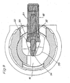
- einen Querschnitt nach Fig. 6 mit einem in der Ausgangsstellung befindlichen Spannteil,
- Fign.10 bis 13
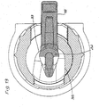
- Darstellungen nach Fig. 9 in einer 60°-, in einer 90°-, in einer 120°- und in einer 180°-Stellung des Spannteiles.
- Der Beschlag nach Fig. 1 besteht aus einem Oberteil 1, einem Unterteil 2, und einem Spannteil 3. Diese drei Teile sind zentrisch übereinander angeordnet und durch aus der Zeichnung nicht erkennbare Sollbruchstellen miteinander verbunden. Sobald auf das Gehäuseoberteil 1 Druck ausgeübt wird, schieben sich das Spannteil 3 in und das Gehäuseoberteil 1 auf das Gehäuseunterteil 2, bis die Ansätze 4 des Oberteils 1 in die Ausnehmungen 5 des Unterteils 2 einrasten, wie dies in Fig. 2 dargestellt ist.
- Nach Fig. 3 ist der Anzugsbolzen 6 mit seinem Schaft 7 in die Bohrung 8 einer Platte 9 eingeschraubt, und zwar bis zu dem ringförmigen Flansch 10. Das Gehäuse 1,2 wird dann in die Bohrung 11 der zweiten Platte 12 eingesetzt, worauf die beiden Platten 9 und 12 zusammengedrückt werden. Anschließend wird der Kopf 13 des Anzugsbolzens 6 durch die Öffnung 14 des Gehäuses 1,2 in das Spannteil 3 eingesetzt, worauf dann durch entsprechendes Drehen des Spannteils 3 der Anzugsbolzen 6 angezogen und damit die Platten 9 und 12 fest miteinander verbunden werden.
- In Fig. 4 ist eine weitere Ausführungsform des erfindungsgemäßen Beschlages dargestellt. Das Gehäuseoberteil 14, das Spannteil 16 und das Gehäuseunterteil 17. liegen zentrisch übereinander und sind durch nicht dargestellte Sollbruchstellen miteinander verbunden. Zusätzlich ist noch ein Anzugsbolzen 18 vorgesehen, welcher über eine Sollbruchstelle 36 mit dem Spannteil 16 verbunden ist. Zur Montage der Teile wird der Anzugsbolzen 18 vom Spannteil 16 gelöst und, wie Fig. 5 zeigt, in dieses eingesetzt. Anschließend erfolgt dann wiederum das Zusammenpressen von Gehäuseoberteil 14 und Gehäuseunterteil 17, bis sich der einsatzbereite Beschlag 15 nach Fig. 6 ergibt. Die Verrastung erfolgt auch hier wiederum durch Ansätze 19 und Rastausnehmungen 20.
- Der Anzugsbolzen 18 weist einen Schaft 21 und einen Kopf 22 auf. Am freien Ende sind schwenkbar zwei Widerhaken 23,24 vorgesehen. Das Gehäuse 14, 17 ist mit einer Hülse 25 versehen, welche an ihrem freien Ende zwei sich gegenüberliegende Auflaufschrägen 26 für die Widerhaken 23, 24 aufweist.
- In den Fign. 7 und 8 ist das Zusammenwirken der Widerhaken 23, 24 mit den Auflaufschrägen 26 dargestellt. In der Platte 27 ist eine Bohrung 29 für den Anzugsbolzen 18 und in der Platte 28 eine Ausnehmung 30 für das Gehäuse 15 vorgesehen. Zum Verbinden der beiden Platten 27 und 28 werden zunächst das Gehäuse 15 in die Ausnehmung 30 und anschließend der Anzugsbolzen 18 in die Ausnehmung 29 eingeführt. Beim Drehen des Spannteils 16 wird der Anzugsbolzen 18 in Pfeilrichtung 31 bewegt, wobei die Widerhaken 23 und 24 auf die Auflaufschrägen 26 auflaufen und sich dabei, wie Fig. 8 zeigt, spreizen und in das Material der Platte 27 eingreifen, wodurch sich ein absolut fester Sitz des Anzugsbolzens 18 in der Platte 27 und damit auch eine gute Verbindung beider Platten 27,28 ergibt.
- In den Fign. 9 bis 13 sind fünf Stellungen des Spannteils 16 und des Anzugsbolzen 18 zwischen 0° und 180° dargestellt. Dabei stützt sich der zum Schaft 18 gerichtete Kopfteil 32 an der Anzugskurve 33 ab, während das freie Kopfende 34 an der Ausstoßkurve 35 anliegt. Beim Anzug des Anzugsbolzens 18 dreht sich das Spannteil 16 entgegen dem Uhrzeigersinn und zieht den Anzugsbolzen bis in die in Fig. 13 gezeigte Stellung. Bei einer Drehung des Spannteils 16 im Uhrzeigersinn wird der Spannbolzen dagegen durch die Anlage seines freien Kopfendes 14 an der Kurve 35 in seine Ursprungslage nach Fig. 9 zurückbewegt. Dabei rutschen die Widerhaken 23 und 24 von den Auflaufschrägen 26 ab und gehen durch ihre Anlage an den Wänden der Bohrung 29 wieder an ihre Ursprungslage nach Fig. 7 zurück, so dass man dann die Platten 27 und 28 ohne weiteres wieder trennen kann.
Claims (7)
- Beschlag zur lösbaren Verbindung zweier Platten (9,12 u. 27,28), insbesondere Möbelplatten, mit einem in einem Gehäuse (1,2 u.14,17) aus einer Freigabe in eine Sperrstellung drehbaren Spannteil (3,16), welches den Kopf (13,22) eines zugehörigen Anzugsbolzens (6,18) Aufnimmt wobei, das Gehäuse aus einem Ober- (1,15) und einem Unterteil (2,17) besteht, welche rastbar miteinander verbindbar sind, dadurch gekennzeichnet, dass die beiden Teile und das zwischen ihnen angeordnete Spannteil (3,16) in einem Arbeitsgang über Sollbruchstellen zusammenhängend gefertigt sind.
- Beschlag nach Anspruch 1, dadurch gekennzeichnet, dass sich vor der Montage das Spannteil (3,16) über dem Gehäuseunterteil (2,17) und das Gehäuseoberteil (1,15) über dem Spannteil jeweils zentrisch zueinander angeordnet befinden.
- Beschlag nach einem oder beiden der Ansprüche 1 und 2, dadurch gekennzeichnet, dass zusammen mit dem Gehäuse (14) und dem Spannteil (16) zusätzlich auch der Anzugsbolzen (18) in einem Arbeitsgang über eine Sollbruchstelle (36) zusammenhängend gefertigt ist.
- Beschlag nach einem oder mehreren der vorhergehenden Ansprüche, dadurch gekennzeichnet, dass vor der Rastverbindung der Gehäuseteile (15,17) der abgetrennte Kopf (22) des Anzugsbolzen (18) im Spannteil liegt, aus welchem das freie Ende seines Schaftes herausragt.
- Beschlag nach einem oder mehreren der vorhergehenden Ansprüche, dadurch gekennzeichnet, dass am Gehäuse (14) eine Hülse (25) zur Führung des Anzugsbolzens (18) angeordnet ist.
- Beschlag nach Anspruch 5, dadurch gekennzeichnet, dass der Anzugsbolzen (18) an seinem dem Kopf (22) entgegengesetzten Ende mit ausschwenkbaren Widerhaken (23,24) versehen ist, welche mit am freien Ende der Hülse (25) vorgesehenen Auflaufschrägen (26) oder mit einem kegelstumpfförmig ausgebildeten Hülsenende sich spreizend zusammenwirken.
- Beschlag mit einem Anzugsbolzen, bestehend aus einem Schaft (21) mit Kopf (22), wobei der Schaft gegenüber dem Kopf im Durchmesser abgesetzt ist, nach einem oder mehreren der vorhergehenden Ansprüche, dadurch gekennzeichnet, dass das Spannteil (16) zwei sich etwa gegenüberliegende Spannkurven aufweist, wobei der zum Schaft (21) gerichtete Kopfteil (32) des Anzugsbolzens (18) an einer Anzugskurve (33) und das freie Kopfende (34) an einer Ausstoßkurve (35) anliegen.
Priority Applications (1)
| Application Number | Priority Date | Filing Date | Title |
|---|---|---|---|
| SI200430021T SI1450052T1 (sl) | 2003-02-19 | 2004-01-20 | Sponski okov |
Applications Claiming Priority (2)
| Application Number | Priority Date | Filing Date | Title |
|---|---|---|---|
| DE20302694U | 2003-02-19 | ||
| DE20302694U DE20302694U1 (de) | 2003-02-19 | 2003-02-19 | Beschlag |
Publications (2)
| Publication Number | Publication Date |
|---|---|
| EP1450052A1 EP1450052A1 (de) | 2004-08-25 |
| EP1450052B1 true EP1450052B1 (de) | 2006-03-08 |
Family
ID=7980175
Family Applications (1)
| Application Number | Title | Priority Date | Filing Date |
|---|---|---|---|
| EP04001050A Expired - Lifetime EP1450052B1 (de) | 2003-02-19 | 2004-01-20 | Beschlag |
Country Status (9)
| Country | Link |
|---|---|
| US (1) | US6939075B2 (de) |
| EP (1) | EP1450052B1 (de) |
| AT (1) | ATE319941T1 (de) |
| DE (2) | DE20302694U1 (de) |
| DK (1) | DK1450052T3 (de) |
| ES (1) | ES2260699T3 (de) |
| PL (1) | PL201050B1 (de) |
| RU (1) | RU2262620C1 (de) |
| SI (1) | SI1450052T1 (de) |
Families Citing this family (24)
| Publication number | Priority date | Publication date | Assignee | Title |
|---|---|---|---|---|
| DE202004000473U1 (de) * | 2004-01-14 | 2004-04-01 | Häfele GmbH & Co. KG | Verbindungsbeschlag für Hohlplatten |
| DE202004006730U1 (de) * | 2004-04-27 | 2005-09-08 | Hettich-Heinze Gmbh & Co. Kg | Verbindungsbeschlag zum Verbinden zweier Möbelteile |
| DE202004012350U1 (de) * | 2004-08-06 | 2004-10-21 | Häfele GmbH & Co KG | Verbindungsbeschlag für Platten, insbesondere für Tablare |
| DE202005001451U1 (de) * | 2005-01-29 | 2005-04-14 | Häfele GmbH & Co KG | Verbinder für Platten, insbesondere für Tablare |
| US20080292837A1 (en) * | 2007-05-21 | 2008-11-27 | Mackal Glenn H | Apparatus and Method for Injection Molding a Fully-Assembled Multi-Component Articulatable Device |
| US8123311B2 (en) * | 2008-04-23 | 2012-02-28 | Robert Nilsson | Portable display system and associated methods |
| GB0815236D0 (en) * | 2008-08-20 | 2008-09-24 | Titus Int Plc | Camming element for fastener |
| US20100202852A1 (en) * | 2009-02-09 | 2010-08-12 | Krause Steven T | No-tools panel coupler and insert |
| DE202009010237U1 (de) * | 2009-07-28 | 2009-12-10 | Häfele GmbH & Co KG | Tablarträger und Tablaranordnung |
| US8579122B2 (en) * | 2011-03-29 | 2013-11-12 | Dimension Espacio, S.A. De C.V. | Modular system for display |
| US8562239B1 (en) * | 2012-04-24 | 2013-10-22 | Min-Sheng Liu | Joint with a protrusion rod for furniture |
| US8819973B2 (en) * | 2012-09-13 | 2014-09-02 | Howard Grayston Mochel | Front loading frame on rail display system |
| DE202015103874U1 (de) | 2015-07-23 | 2016-10-25 | Grass Gmbh | Vorrichtung zum Verbinden zweier Möbelteile |
| ITUB20154290A1 (it) * | 2015-10-09 | 2017-04-09 | Leonardo Srl | Dispositivo di giunzione ad ampia accessibilita? per parti di mobili e articoli da arredamento |
| DE202016101880U1 (de) | 2016-04-11 | 2016-04-27 | Häfele Berlin Gmbh & Co Kg | Beschlag zum lösbaren Verbinden zweier Möbelteile |
| IT201600070959A1 (it) * | 2016-07-07 | 2018-01-07 | Leonardo Srl | Giunzione per intercollegare stabilmente un primo e un secondo pannello di mobili e di altri articoli da arredamento |
| US10443635B2 (en) * | 2016-10-18 | 2019-10-15 | The Boeing Company | Panel fastening system |
| DE202017106045U1 (de) | 2017-10-05 | 2017-11-23 | Häfele GmbH & Co KG | Verbinder zum Stoßverbinden zweier Bauteile |
| USD911813S1 (en) * | 2018-02-23 | 2021-03-02 | Mcs Industries, Inc. | Cam lock |
| CN112065834A (zh) * | 2020-10-09 | 2020-12-11 | 佛山市艾锐特五金制品有限公司 | 一种免预埋件快装连接杆及使用方法 |
| CN115076197B (zh) * | 2022-07-27 | 2023-03-10 | 常州市凯迪电器股份有限公司 | 一种旋拨连接结构、快速安装支架、升降组件及安装方法 |
| CA3212836A1 (en) * | 2022-09-15 | 2024-03-15 | Systemes Norbec Inc. | Insulated panel connection |
| DE102023124315A1 (de) * | 2023-09-08 | 2025-03-13 | Hettich-Heinze Gmbh & Co. Kg | Verbindungsbeschlag, Möbel und Verfahren zur Montage |
| KR102936730B1 (ko) * | 2024-03-22 | 2026-03-06 | 백화옥 | 조립가구용 밀착 연결장치 |
Family Cites Families (12)
| Publication number | Priority date | Publication date | Assignee | Title |
|---|---|---|---|---|
| GR64219B (en) * | 1977-03-16 | 1980-02-12 | Unerman Greenman Berger Ltd | A coupling device primarily for connecting two sections of an article of furniture |
| DE3269151D1 (en) * | 1982-06-16 | 1986-03-27 | Salice Arturo Spa | Joining means |
| JPH01203705A (ja) * | 1988-02-04 | 1989-08-16 | Kazuhiro Matsui | 板状体の組立具 |
| JPH0280804A (ja) * | 1988-09-13 | 1990-03-20 | Kojima Shoten:Kk | 組立具 |
| DE8900182U1 (de) * | 1989-01-09 | 1989-05-11 | G & G Beschläge GmbH, 7270 Nagold | Möbelbeschlag |
| DE4437273C2 (de) * | 1994-10-18 | 1996-09-26 | Salice Arturo Spa | Verbindungsbeschlag |
| GB2301644B (en) * | 1995-05-31 | 1999-03-10 | Titus Int Plc | Joint forming devices |
| GB2301413B (en) * | 1995-05-31 | 1999-03-10 | Titus Int Plc | Joint forming devices |
| DE29510504U1 (de) * | 1995-06-28 | 1995-09-07 | Arturo Salice S.P.A., Novedrate, Como | Verbindungsbeschlag |
| DE29714853U1 (de) * | 1997-08-19 | 1997-10-16 | Häfele GmbH & Co, 72202 Nagold | Einteiliger Beschlag |
| DE29721068U1 (de) * | 1997-11-27 | 1998-01-22 | Arturo Salice S.P.A., Novedrate, Como | Verbindungsbeschlag |
| DE29804267U1 (de) * | 1998-03-11 | 1999-07-15 | Häfele GmbH & Co, 72202 Nagold | Verbinder zwischen zwei Bauteilen, insbesondere Platten |
-
2003
- 2003-02-19 DE DE20302694U patent/DE20302694U1/de not_active Expired - Lifetime
-
2004
- 2004-01-20 DE DE502004000328T patent/DE502004000328D1/de not_active Expired - Lifetime
- 2004-01-20 AT AT04001050T patent/ATE319941T1/de not_active IP Right Cessation
- 2004-01-20 ES ES04001050T patent/ES2260699T3/es not_active Expired - Lifetime
- 2004-01-20 EP EP04001050A patent/EP1450052B1/de not_active Expired - Lifetime
- 2004-01-20 DK DK04001050T patent/DK1450052T3/da active
- 2004-01-20 SI SI200430021T patent/SI1450052T1/sl unknown
- 2004-02-14 US US10/778,730 patent/US6939075B2/en not_active Expired - Fee Related
- 2004-02-16 PL PL365260A patent/PL201050B1/pl unknown
- 2004-02-18 RU RU2004104994/11A patent/RU2262620C1/ru active
Also Published As
| Publication number | Publication date |
|---|---|
| DE20302694U1 (de) | 2003-06-12 |
| RU2004104994A (ru) | 2005-07-27 |
| PL201050B1 (pl) | 2009-03-31 |
| SI1450052T1 (sl) | 2006-06-30 |
| DE502004000328D1 (de) | 2006-05-04 |
| RU2262620C1 (ru) | 2005-10-20 |
| ATE319941T1 (de) | 2006-03-15 |
| ES2260699T3 (es) | 2006-11-01 |
| PL365260A1 (en) | 2004-08-23 |
| US6939075B2 (en) | 2005-09-06 |
| EP1450052A1 (de) | 2004-08-25 |
| DK1450052T3 (da) | 2006-07-10 |
| US20040161294A1 (en) | 2004-08-19 |
Similar Documents
| Publication | Publication Date | Title |
|---|---|---|
| EP1450052A1 (de) | Beschlag | |
| DE19505311C2 (de) | Befestigungsanordnung von Beschlägen, insbesondere Möbelbeschlägen an Möbelstücken | |
| EP2094369B1 (de) | Filtergehäuse und herstellungsverfahren | |
| EP1454071A1 (de) | Verbindungsmutter zum anschrauben von konstruktionselementen an einem plattenartigen bauteil | |
| EP1343974B2 (de) | Verbindereinrichtung für profile | |
| DE102012007996A1 (de) | Toleranzausgleichsanordnung mit Ausdrehsicherung | |
| EP0272519A1 (de) | Verbindungsbeschlag | |
| DE102005032699B4 (de) | Befestigungsvorrichtung | |
| DE2610200A1 (de) | Beschlag zum loesbaren verbinden von bauteilen, insbesondere zum wieder loesbaren verbinden von plattenfoermigen bauteilen | |
| EP3379129A1 (de) | Anschlussverbinder | |
| EP3122981B1 (de) | Dichtungsvorrichtung und befestigungsmittel | |
| DE102016124805B4 (de) | Membranventil | |
| DE102006016277A1 (de) | Schnellverschluss | |
| DE2615322C2 (de) | Befestigungsvorrichtung für Türschilder bzw. Türrosetten | |
| EP2918354B1 (de) | Pressaufsatz zum axialen Verpressen von Werkstücken | |
| DE102013208494A1 (de) | Vorrichtung zur werkzeuglosen Verbindung zweier Bauteile | |
| EP3819645A1 (de) | Versteifungselement zum versteifen eines testkontaktorsystems, verwendung und verfahren zur montage eines testkontaktorsystems | |
| EP0791759A1 (de) | Schnellverschluss | |
| EP2012024A2 (de) | Befestigungsklammer zur Verbindung zweier aufeinanderliegender flacher Bauteile | |
| EP4047219A1 (de) | Montage-einheit mit zumindest einer montageschiene sowie wenigstens einer halteklammer | |
| AT518841B1 (de) | Mutter für eine Schraubverbindung,Schraubverbindung mit der Mutter, sowie WC-Sitzgarnitur mit der Schraubverbindung | |
| DE2546750A1 (de) | Beschlag zum loesbaren verbinden zweier senkrecht aufeinanderstossender plattenfoermiger bauteile | |
| DE10357646B4 (de) | Wanddurchführung | |
| DE102006022890A1 (de) | Befestigungssystem mit einem Clip | |
| EP0512144A1 (de) | Brennstoffiltereinheit |
Legal Events
| Date | Code | Title | Description |
|---|---|---|---|
| PUAI | Public reference made under article 153(3) epc to a published international application that has entered the european phase |
Free format text: ORIGINAL CODE: 0009012 |
|
| AK | Designated contracting states |
Kind code of ref document: A1 Designated state(s): AT BE BG CH CY CZ DE DK EE ES FI FR GB GR HU IE IT LI LU MC NL PT RO SE SI SK TR |
|
| AX | Request for extension of the european patent |
Extension state: AL LT LV MK |
|
| 17P | Request for examination filed |
Effective date: 20040714 |
|
| AKX | Designation fees paid |
Designated state(s): AT BE BG CH CY CZ DE DK EE ES FI FR GB GR HU IE IT LI LU MC NL PT RO SE SI SK TR |
|
| GRAP | Despatch of communication of intention to grant a patent |
Free format text: ORIGINAL CODE: EPIDOSNIGR1 |
|
| GRAS | Grant fee paid |
Free format text: ORIGINAL CODE: EPIDOSNIGR3 |
|
| GRAA | (expected) grant |
Free format text: ORIGINAL CODE: 0009210 |
|
| AK | Designated contracting states |
Kind code of ref document: B1 Designated state(s): AT BE BG CH CY CZ DE DK EE ES FI FR GB GR HU IE IT LI LU MC NL PT RO SE SI SK TR |
|
| PG25 | Lapsed in a contracting state [announced via postgrant information from national office to epo] |
Ref country code: IT Free format text: LAPSE BECAUSE OF FAILURE TO SUBMIT A TRANSLATION OF THE DESCRIPTION OR TO PAY THE FEE WITHIN THE PRESCRIBED TIME-LIMIT;WARNING: LAPSES OF ITALIAN PATENTS WITH EFFECTIVE DATE BEFORE 2007 MAY HAVE OCCURRED AT ANY TIME BEFORE 2007. THE CORRECT EFFECTIVE DATE MAY BE DIFFERENT FROM THE ONE RECORDED. Effective date: 20060308 Ref country code: NL Free format text: LAPSE BECAUSE OF FAILURE TO SUBMIT A TRANSLATION OF THE DESCRIPTION OR TO PAY THE FEE WITHIN THE PRESCRIBED TIME-LIMIT Effective date: 20060308 Ref country code: RO Free format text: LAPSE BECAUSE OF FAILURE TO SUBMIT A TRANSLATION OF THE DESCRIPTION OR TO PAY THE FEE WITHIN THE PRESCRIBED TIME-LIMIT Effective date: 20060308 Ref country code: IE Free format text: LAPSE BECAUSE OF FAILURE TO SUBMIT A TRANSLATION OF THE DESCRIPTION OR TO PAY THE FEE WITHIN THE PRESCRIBED TIME-LIMIT Effective date: 20060308 |
|
| REG | Reference to a national code |
Ref country code: GB Ref legal event code: FG4D Free format text: NOT ENGLISH |
|
| REG | Reference to a national code |
Ref country code: CH Ref legal event code: EP |
|
| REG | Reference to a national code |
Ref country code: IE Ref legal event code: FG4D Free format text: LANGUAGE OF EP DOCUMENT: GERMAN |
|
| GBT | Gb: translation of ep patent filed (gb section 77(6)(a)/1977) |
Effective date: 20060327 |
|
| REF | Corresponds to: |
Ref document number: 502004000328 Country of ref document: DE Date of ref document: 20060504 Kind code of ref document: P |
|
| PG25 | Lapsed in a contracting state [announced via postgrant information from national office to epo] |
Ref country code: BG Free format text: LAPSE BECAUSE OF FAILURE TO SUBMIT A TRANSLATION OF THE DESCRIPTION OR TO PAY THE FEE WITHIN THE PRESCRIBED TIME-LIMIT Effective date: 20060608 |
|
| REG | Reference to a national code |
Ref country code: GR Ref legal event code: EP Ref document number: 20060401674 Country of ref document: GR |
|
| REG | Reference to a national code |
Ref country code: SE Ref legal event code: TRGR |
|
| REG | Reference to a national code |
Ref country code: DK Ref legal event code: T3 |
|
| PG25 | Lapsed in a contracting state [announced via postgrant information from national office to epo] |
Ref country code: PT Free format text: LAPSE BECAUSE OF FAILURE TO SUBMIT A TRANSLATION OF THE DESCRIPTION OR TO PAY THE FEE WITHIN THE PRESCRIBED TIME-LIMIT Effective date: 20060808 |
|
| ET | Fr: translation filed | ||
| NLV1 | Nl: lapsed or annulled due to failure to fulfill the requirements of art. 29p and 29m of the patents act | ||
| REG | Reference to a national code |
Ref country code: IE Ref legal event code: FD4D |
|
| REG | Reference to a national code |
Ref country code: ES Ref legal event code: FG2A Ref document number: 2260699 Country of ref document: ES Kind code of ref document: T3 |
|
| PLBE | No opposition filed within time limit |
Free format text: ORIGINAL CODE: 0009261 |
|
| STAA | Information on the status of an ep patent application or granted ep patent |
Free format text: STATUS: NO OPPOSITION FILED WITHIN TIME LIMIT |
|
| PG25 | Lapsed in a contracting state [announced via postgrant information from national office to epo] |
Ref country code: MC Free format text: LAPSE BECAUSE OF NON-PAYMENT OF DUE FEES Effective date: 20070131 |
|
| 26N | No opposition filed |
Effective date: 20061211 |
|
| PG25 | Lapsed in a contracting state [announced via postgrant information from national office to epo] |
Ref country code: AT Free format text: LAPSE BECAUSE OF NON-PAYMENT OF DUE FEES Effective date: 20070120 |
|
| PG25 | Lapsed in a contracting state [announced via postgrant information from national office to epo] |
Ref country code: EE Free format text: LAPSE BECAUSE OF FAILURE TO SUBMIT A TRANSLATION OF THE DESCRIPTION OR TO PAY THE FEE WITHIN THE PRESCRIBED TIME-LIMIT Effective date: 20060308 |
|
| REG | Reference to a national code |
Ref country code: CH Ref legal event code: PL |
|
| PG25 | Lapsed in a contracting state [announced via postgrant information from national office to epo] |
Ref country code: LI Free format text: LAPSE BECAUSE OF NON-PAYMENT OF DUE FEES Effective date: 20080131 Ref country code: CH Free format text: LAPSE BECAUSE OF NON-PAYMENT OF DUE FEES Effective date: 20080131 |
|
| PGFP | Annual fee paid to national office [announced via postgrant information from national office to epo] |
Ref country code: SK Payment date: 20081219 Year of fee payment: 6 |
|
| PGFP | Annual fee paid to national office [announced via postgrant information from national office to epo] |
Ref country code: GR Payment date: 20081219 Year of fee payment: 6 |
|
| PG25 | Lapsed in a contracting state [announced via postgrant information from national office to epo] |
Ref country code: CY Free format text: LAPSE BECAUSE OF FAILURE TO SUBMIT A TRANSLATION OF THE DESCRIPTION OR TO PAY THE FEE WITHIN THE PRESCRIBED TIME-LIMIT Effective date: 20060308 Ref country code: LU Free format text: LAPSE BECAUSE OF NON-PAYMENT OF DUE FEES Effective date: 20070120 |
|
| PG25 | Lapsed in a contracting state [announced via postgrant information from national office to epo] |
Ref country code: HU Free format text: LAPSE BECAUSE OF FAILURE TO SUBMIT A TRANSLATION OF THE DESCRIPTION OR TO PAY THE FEE WITHIN THE PRESCRIBED TIME-LIMIT Effective date: 20060909 |
|
| REG | Reference to a national code |
Ref country code: SK Ref legal event code: MM4A Ref document number: E 602 Country of ref document: SK Effective date: 20100120 |
|
| PG25 | Lapsed in a contracting state [announced via postgrant information from national office to epo] |
Ref country code: SK Free format text: LAPSE BECAUSE OF NON-PAYMENT OF DUE FEES Effective date: 20100120 |
|
| PGFP | Annual fee paid to national office [announced via postgrant information from national office to epo] |
Ref country code: FI Payment date: 20110124 Year of fee payment: 8 |
|
| PGFP | Annual fee paid to national office [announced via postgrant information from national office to epo] |
Ref country code: BE Payment date: 20110124 Year of fee payment: 8 |
|
| PGFP | Annual fee paid to national office [announced via postgrant information from national office to epo] |
Ref country code: GB Payment date: 20110121 Year of fee payment: 8 |
|
| PGFP | Annual fee paid to national office [announced via postgrant information from national office to epo] |
Ref country code: FR Payment date: 20120201 Year of fee payment: 9 |
|
| PGFP | Annual fee paid to national office [announced via postgrant information from national office to epo] |
Ref country code: SE Payment date: 20120126 Year of fee payment: 9 |
|
| BERE | Be: lapsed |
Owner name: *HAFELE G.M.B.H. & CO. K.G. Effective date: 20120131 |
|
| GBPC | Gb: european patent ceased through non-payment of renewal fee |
Effective date: 20120120 |
|
| PG25 | Lapsed in a contracting state [announced via postgrant information from national office to epo] |
Ref country code: GB Free format text: LAPSE BECAUSE OF NON-PAYMENT OF DUE FEES Effective date: 20120120 Ref country code: FI Free format text: LAPSE BECAUSE OF NON-PAYMENT OF DUE FEES Effective date: 20120120 |
|
| PG25 | Lapsed in a contracting state [announced via postgrant information from national office to epo] |
Ref country code: BE Free format text: LAPSE BECAUSE OF NON-PAYMENT OF DUE FEES Effective date: 20120131 |
|
| PGFP | Annual fee paid to national office [announced via postgrant information from national office to epo] |
Ref country code: CZ Payment date: 20121207 Year of fee payment: 10 |
|
| REG | Reference to a national code |
Ref country code: SE Ref legal event code: EUG |
|
| REG | Reference to a national code |
Ref country code: FR Ref legal event code: ST Effective date: 20130930 |
|
| PG25 | Lapsed in a contracting state [announced via postgrant information from national office to epo] |
Ref country code: SE Free format text: LAPSE BECAUSE OF NON-PAYMENT OF DUE FEES Effective date: 20130121 |
|
| PG25 | Lapsed in a contracting state [announced via postgrant information from national office to epo] |
Ref country code: FR Free format text: LAPSE BECAUSE OF NON-PAYMENT OF DUE FEES Effective date: 20130131 |
|
| PG25 | Lapsed in a contracting state [announced via postgrant information from national office to epo] |
Ref country code: CZ Free format text: LAPSE BECAUSE OF NON-PAYMENT OF DUE FEES Effective date: 20140120 |
|
| PGFP | Annual fee paid to national office [announced via postgrant information from national office to epo] |
Ref country code: ES Payment date: 20230216 Year of fee payment: 20 Ref country code: DK Payment date: 20230123 Year of fee payment: 20 |
|
| PGFP | Annual fee paid to national office [announced via postgrant information from national office to epo] |
Ref country code: TR Payment date: 20230118 Year of fee payment: 20 Ref country code: SI Payment date: 20230112 Year of fee payment: 20 Ref country code: IT Payment date: 20230131 Year of fee payment: 20 Ref country code: DE Payment date: 20230126 Year of fee payment: 20 |
|
| P01 | Opt-out of the competence of the unified patent court (upc) registered |
Effective date: 20230630 |
|
| REG | Reference to a national code |
Ref country code: DE Ref legal event code: R071 Ref document number: 502004000328 Country of ref document: DE |
|
| REG | Reference to a national code |
Ref country code: DK Ref legal event code: EUP Expiry date: 20240120 |
|
| REG | Reference to a national code |
Ref country code: ES Ref legal event code: FD2A Effective date: 20240126 |
|
| PG25 | Lapsed in a contracting state [announced via postgrant information from national office to epo] |
Ref country code: SI Free format text: LAPSE BECAUSE OF EXPIRATION OF PROTECTION Effective date: 20240121 |
|
| PG25 | Lapsed in a contracting state [announced via postgrant information from national office to epo] |
Ref country code: ES Free format text: LAPSE BECAUSE OF EXPIRATION OF PROTECTION Effective date: 20240121 |
|
| PG25 | Lapsed in a contracting state [announced via postgrant information from national office to epo] |
Ref country code: ES Free format text: LAPSE BECAUSE OF EXPIRATION OF PROTECTION Effective date: 20240121 |