EP1449722B1 - Véhicule à moteur équipé d'un marchepied escamotable - Google Patents
Véhicule à moteur équipé d'un marchepied escamotable Download PDFInfo
- Publication number
- EP1449722B1 EP1449722B1 EP04100124A EP04100124A EP1449722B1 EP 1449722 B1 EP1449722 B1 EP 1449722B1 EP 04100124 A EP04100124 A EP 04100124A EP 04100124 A EP04100124 A EP 04100124A EP 1449722 B1 EP1449722 B1 EP 1449722B1
- Authority
- EP
- European Patent Office
- Prior art keywords
- steps
- motor vehicle
- door
- rotation
- extended position
- Prior art date
- Legal status (The legal status is an assumption and is not a legal conclusion. Google has not performed a legal analysis and makes no representation as to the accuracy of the status listed.)
- Expired - Lifetime
Links
- 230000035939 shock Effects 0.000 description 2
- 230000009471 action Effects 0.000 description 1
- 230000009194 climbing Effects 0.000 description 1
- 238000010276 construction Methods 0.000 description 1
- 230000036541 health Effects 0.000 description 1
- 230000007246 mechanism Effects 0.000 description 1
- 230000004048 modification Effects 0.000 description 1
- 238000012986 modification Methods 0.000 description 1
- 239000002689 soil Substances 0.000 description 1
- 230000002747 voluntary effect Effects 0.000 description 1
Images
Classifications
-
- B—PERFORMING OPERATIONS; TRANSPORTING
- B66—HOISTING; LIFTING; HAULING
- B66F—HOISTING, LIFTING, HAULING OR PUSHING, NOT OTHERWISE PROVIDED FOR, e.g. DEVICES WHICH APPLY A LIFTING OR PUSHING FORCE DIRECTLY TO THE SURFACE OF A LOAD
- B66F9/00—Devices for lifting or lowering bulky or heavy goods for loading or unloading purposes
- B66F9/06—Devices for lifting or lowering bulky or heavy goods for loading or unloading purposes movable, with their loads, on wheels or the like, e.g. fork-lift trucks
- B66F9/065—Devices for lifting or lowering bulky or heavy goods for loading or unloading purposes movable, with their loads, on wheels or the like, e.g. fork-lift trucks non-masted
-
- B—PERFORMING OPERATIONS; TRANSPORTING
- B60—VEHICLES IN GENERAL
- B60R—VEHICLES, VEHICLE FITTINGS, OR VEHICLE PARTS, NOT OTHERWISE PROVIDED FOR
- B60R3/00—Arrangements of steps or ladders facilitating access to or on the vehicle, e.g. running-boards
- B60R3/02—Retractable steps or ladders, e.g. movable under shock
-
- B—PERFORMING OPERATIONS; TRANSPORTING
- B66—HOISTING; LIFTING; HAULING
- B66F—HOISTING, LIFTING, HAULING OR PUSHING, NOT OTHERWISE PROVIDED FOR, e.g. DEVICES WHICH APPLY A LIFTING OR PUSHING FORCE DIRECTLY TO THE SURFACE OF A LOAD
- B66F9/00—Devices for lifting or lowering bulky or heavy goods for loading or unloading purposes
- B66F9/06—Devices for lifting or lowering bulky or heavy goods for loading or unloading purposes movable, with their loads, on wheels or the like, e.g. fork-lift trucks
- B66F9/075—Constructional features or details
- B66F9/07504—Accessories, e.g. for towing, charging, locking
-
- B—PERFORMING OPERATIONS; TRANSPORTING
- B66—HOISTING; LIFTING; HAULING
- B66F—HOISTING, LIFTING, HAULING OR PUSHING, NOT OTHERWISE PROVIDED FOR, e.g. DEVICES WHICH APPLY A LIFTING OR PUSHING FORCE DIRECTLY TO THE SURFACE OF A LOAD
- B66F9/00—Devices for lifting or lowering bulky or heavy goods for loading or unloading purposes
- B66F9/06—Devices for lifting or lowering bulky or heavy goods for loading or unloading purposes movable, with their loads, on wheels or the like, e.g. fork-lift trucks
- B66F9/075—Constructional features or details
- B66F9/0759—Details of operating station, e.g. seats, levers, operator platforms, cabin suspension
-
- E—FIXED CONSTRUCTIONS
- E02—HYDRAULIC ENGINEERING; FOUNDATIONS; SOIL SHIFTING
- E02F—DREDGING; SOIL-SHIFTING
- E02F3/00—Dredgers; Soil-shifting machines
- E02F3/04—Dredgers; Soil-shifting machines mechanically-driven
- E02F3/28—Dredgers; Soil-shifting machines mechanically-driven with digging tools mounted on a dipper- or bucket-arm, i.e. there is either one arm or a pair of arms, e.g. dippers, buckets
- E02F3/283—Dredgers; Soil-shifting machines mechanically-driven with digging tools mounted on a dipper- or bucket-arm, i.e. there is either one arm or a pair of arms, e.g. dippers, buckets with a single arm pivoted directly on the chassis
-
- E—FIXED CONSTRUCTIONS
- E02—HYDRAULIC ENGINEERING; FOUNDATIONS; SOIL SHIFTING
- E02F—DREDGING; SOIL-SHIFTING
- E02F9/00—Component parts of dredgers or soil-shifting machines, not restricted to one of the kinds covered by groups E02F3/00 - E02F7/00
- E02F9/08—Superstructures; Supports for superstructures
- E02F9/0833—Improving access, e.g. for maintenance, steps for improving driver's access, handrails
Definitions
- the present invention relates to a motor vehicle comprising a step according to the preamble of claim 1, as known from US 6,179,312.
- Motor vehicles for example public works machinery handling equipment, loader or elevator, of the type earthmoving loader-excavator or the like include a raised cockpit to allow the operator to have a global vision to thus monitor his work.
- the footboard is centered between the wheels and aligned with the outside jig of the machine.
- the step is often very out of step with the opening of the door. This forces the operator to cling to the mobile door and climb to the uphill cabin. Or, the operator plate laterally against the cab at the descent, so as not to fall before having reached the top step.
- a first problem that the invention proposes to solve is to obtain a system of retractable steps that solves the problems mentioned above.
- a second problem is to equip a motor vehicle and more particularly a public works machine with a step incorporating steps responding to Ergonomic constraints, reliability and robustness necessary for such a body.
- a motor vehicle includes a cockpit for an operator and a footboard with at least two steps to access the cockpit by an opening that can be closed by a door.
- the steps are mobile between a retracted position in which the steps are under the cockpit and a exit position in which the steps are exposed to allow a climb and easy descent of the operator.
- the steps go from the retracted position to the position and vice versa by pivoting with respect to an axis of rotation substantially vertical.
- the motor vehicle is characterized in that the steps are substantially offset on the horizontal, in the position out, relative to each other, and on both sides of the axis of rotation substantially vertical.
- the step can include two steps, located at different heights, an upper step and a lower step. Walking higher can be advantageously substantially rectangular.
- this upper step has a long side which can be positioned substantially parallel to the opening for the door.
- This top step can be favorably positioned at the opening for the cabin door of piloting. The operator therefore sees the first step down and this step is located directly opposite the opening of the cabin.
- the lower step can be substantially rectangular. In the extended position, this lower step has a side long, which can be positioned substantially perpendicular to the opening for the door.
- the steps can each be mounted on a different axis of rotation and substantially vertical.
- the steps can rotate in the opposite direction to move from the position returned to the output position and vice versa.
- a possibility is to mount a hydraulic cylinder that can then operate a cross link for each step.
- Connecting rod references can be mounted to turn on a pivot directly secured to one of the steps.
- the references forming connecting rod can be mounted to rotate on the axis of rotation of another of the steps.
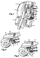
- a motor vehicle for example a public works machine (1), such as shown in Figure 1, comprises a frame (2), wheels (3), an engine compartment (4), work equipment (6), in the form of an articulated arm, at the end of which is installed a working tool (not shown) and a cockpit (7).
- a operator (8) controls the public works machine (1) and accesses the cockpit (7) by an opening (9) closed by a door (11). The operator (8) sits on a seat (12) provided in the cockpit (7).
- a step is provided so that the operator (8) can easily access the cockpit (7).
- the step comprises a substantially lower step horizontal (13) and a substantially horizontal upper step (14).
- the lower step (13) is shifted on the horizontal to the right of an axis vertical (V)
- the upper step (14) is shifted on the horizontal to the left of the axis vertical (V).
- the lower step (13) and the top step (14) are substantially rectangular.
- the upper step (14) has a long side (16) positioned substantially parallel to the opening (9) for the door (11).
- the lower step (13) has a long side (17) positioned substantially perpendicular to the opening (9) for the door (11).
- the first lower step (13) thus has a flange (18) away from the chassis (2) and the public works machine (1), and is easily accessible on the first foot of the operator (8).
- the upper step (14) In the extended position, the upper step (14) is made visible from the top of the cockpit (7). In position with the steps exits (13 and 14), there is no more overhang or directly vertical climb in the cockpit (7).
- the upper step (14) is positioned at the opening (9) for the door (11) of the cockpit (7). So, the last foot movement of the operator (8) allows the latter to enter directly into the cabin (7), without this the last one is made to make a gap and thus without risk of falling.
- the two steps (13 and 14) simultaneously move from the retracted position to the position and vice versa, by pivoting with respect to an axis substantially vertical, these two steps (13 and 14) thus maintaining their horizontality.
- the steps (13 and 14) fit into the jig of the public works machine (1), pass and remain horizontally completely under the frame (2). In position the steps (13 and 14) are protected from possible lateral shocks or by the below.
- the lower step (13) is pivotally mounted on an axis of rotation substantially vertical lower (19).
- the upper step (14) is mounted for pivoting on a substantially vertical upper axis of rotation (21).
- the axis of rotation lower (19) rotates and is held in a bearing (not visible) provided at a level lower bar (22) of the frame (2).
- the upper rotation axis (21) rotates and is maintained in a bearing (not visible) provided at an upper bar (23) of chassis (2).
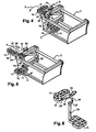
- a hydraulic cylinder (24) allows the passage of the steps (13 and 14) of the position returned to the out position and the out position to the retracted position.
- the cylinder (24) is connected to one end of a first linkage connecting rod (26) and actuates it as well.
- a other end of the first connecting link (26) is then functionally connected to a crank (27).
- This crank (27) is then secured to the axis of lower rotation (19) of the lower step (13).
- the hydraulic cylinder (24) is connected to one end of a second linkage connecting rod (28) and thereby actuates it.
- Another end of the second connecting link (28) is then functionally connected to a pivot (29). This pivot (29) is secured to the upper step (14), offset from the upper axis of rotation (21).
- This kinematic chain makes that horizontal back and forth movements (Arrows A and B) of the hydraulic cylinder (24) rotate in a horizontal plane (Arrows C and D) the lower step (13) and rotate in a horizontal plane (Arrows E and F) the top step (14). Pivots are in opposite directions for move them from the retracted position to the exited position and vice versa.
- the output and the inlet of the hydraulic cylinder (24), and therefore of the steps (13 and 14), are related to the retraction of the headquarters consoles (12), which is a voluntary action obligatory on the part of the operator (8) before any output of the public works machine (1).
- the setting in motion may be related to any other sign of the exit of the operator (8), such as opening the door (11) or a manual action on a button is located inside or outside the public works machine (1).
- the number and shape of the steps can be variable. Hydraulic cylinder double acting or single acting hydraulic cylinder with return spring can be used.
Landscapes
- Engineering & Computer Science (AREA)
- Structural Engineering (AREA)
- Transportation (AREA)
- Civil Engineering (AREA)
- Mechanical Engineering (AREA)
- Life Sciences & Earth Sciences (AREA)
- Geology (AREA)
- Mining & Mineral Resources (AREA)
- General Engineering & Computer Science (AREA)
- Vehicle Step Arrangements And Article Storage (AREA)
- Air Bags (AREA)
- Automobile Manufacture Line, Endless Track Vehicle, Trailer (AREA)
Description
- la Figure 1 représente une vue partielle en perspective d'un engin de travaux publics équipé d'un marchepied selon l'invention ;
- la Figure 2 représente une vue partielle agrandie en perspective de l'engin de travaux publics avec le marchepied en position escamotée ;
- la Figure 3 représente une vue partielle agrandie en perspective de l'engin de travaux publics avec le marchepied en position sortie ;
- la Figure 4 représente une vue en perspective du marchepied en position escamotée ;
- la Figure 5 représente une vue en perspective du marchepied en position sortie ; et
- la Figure 6 représente une vue en perspective du marchepied avec son mécanisme d'escamotage isolé.
Claims (7)
- Véhicule à moteur, comprenant une cabine de pilotage (7) pour un opérateur (8) et un marchepied avec au moins deux marches (13, 14) permettant d'accéder à la cabine de pilotage (7) par une ouverture (9) pouvant être fermée par une porte (11), les marches (13, 14) étant mobiles entre une position rentrée dans laquelle les marches (13, 14) sont sous la cabine de pilotage (7) et une position sortie dans laquelle les marches (13, 14) sont exposées pour permettre une montée et une descente facilitée de l'opérateur (8), lesdites marches (13, 14) passant de la position rentrée à la position sortie et inversement par pivotement par rapport à un axe de rotation sensiblement vertical, caractérisé en ce que les marches (13, 14) sont sensiblement décalées sur l'horizontale, dans la position sortie, l'une par rapport à l'autre, et de part et d'autre de l'axe de rotation sensiblement vertical (V).
- Véhicule à moteur selon la revendication 1, caractérisé en ce que le marchepied comprend deux marches (13, 14), une marche supérieure (14) et une marche inférieure (13) situées à des hauteurs différentes.
- Véhicule à moteur selon la revendication 2, caractérisé en ce que la marche supérieure (14) est sensiblement rectangulaire et présente en position sortie un côté long (16) positionné sensiblement parallèlement à l'ouverture (9) pour la porte (11).
- Véhicule à moteur selon la revendication 2 ou 3, caractérisé en ce que la marche supérieure (14) est positionnée au niveau de l'ouverture (9) pour la porte (11) de la cabine de pilotage (7).
- Véhicule à moteur selon la revendication 2, caractérisé en ce que la marche inférieure (13) est sensiblement rectangulaire et présente en position sortie un côté long (17) positionné sensiblement perpendiculairement à l'ouverture (9) pour la porte (11).
- Véhicule à moteur selon l'une quelconque des revendications précédentes, caractérisé en ce que les marches (13, 14) sont chacune montées sur un axe de rotation différent et sensiblement vertical (19, 21) et pivotent en sens opposé pour passer de la position rentrée à la position sortie et réciproquement
- Véhicule à moteur selon la revendication 6, caractérisé en ce qu'il comprend un vérin hydraulique (24) actionnant un renvoi formant bielle (26, 28) pour chacune des marches (13, 14), et en ce que les renvois formant bielle (26, 28) sont montés pour tourner sur un pivot (29) directement solidarisé à l'une des marches (14) ou pour tourner sur l'axe de rotation (21) d'une autre des marches (13).
Applications Claiming Priority (2)
| Application Number | Priority Date | Filing Date | Title |
|---|---|---|---|
| FR0302213A FR2851527B1 (fr) | 2003-02-24 | 2003-02-24 | Vehicule a moteur equipe d'un marchepied escamotable |
| FR0302213 | 2003-02-24 |
Publications (2)
| Publication Number | Publication Date |
|---|---|
| EP1449722A1 EP1449722A1 (fr) | 2004-08-25 |
| EP1449722B1 true EP1449722B1 (fr) | 2005-08-31 |
Family
ID=32732054
Family Applications (1)
| Application Number | Title | Priority Date | Filing Date |
|---|---|---|---|
| EP04100124A Expired - Lifetime EP1449722B1 (fr) | 2003-02-24 | 2004-01-15 | Véhicule à moteur équipé d'un marchepied escamotable |
Country Status (4)
| Country | Link |
|---|---|
| EP (1) | EP1449722B1 (fr) |
| AT (1) | ATE303266T1 (fr) |
| DE (1) | DE602004000067T2 (fr) |
| FR (1) | FR2851527B1 (fr) |
Families Citing this family (6)
| Publication number | Priority date | Publication date | Assignee | Title |
|---|---|---|---|---|
| US7219911B2 (en) * | 2004-10-18 | 2007-05-22 | Ventra Group Inc. | Retractable vehicle step assembly |
| DE202006016432U1 (de) * | 2006-10-26 | 2008-02-28 | Gebr. Bode Gmbh & Co. Kg | Ein-/Ausstiegsvorrichtung für ein Fahrzeug des öffentlichen Personen-Verkehrs mit einem in einem Rahmen angeordneten Schiebetritt |
| GB0719055D0 (en) * | 2007-09-29 | 2007-11-07 | Passenger Lift Services Ltd | A step for a vehicle |
| CN101480936B (zh) * | 2009-02-25 | 2010-08-18 | 张建明 | 消防车的活动踏脚板装置 |
| US9404238B1 (en) * | 2015-01-10 | 2016-08-02 | Bauer Maschinen Gmbh | Construction machine |
| FR3031492B1 (fr) * | 2015-01-12 | 2017-01-13 | Groupe Mecalac | Marchepied escamotable |
Family Cites Families (6)
| Publication number | Priority date | Publication date | Assignee | Title |
|---|---|---|---|---|
| US3388925A (en) * | 1966-12-05 | 1968-06-18 | Salvador V. Chavira | Truck step |
| SE427641B (sv) * | 1979-05-31 | 1983-04-25 | Kockums Landsverk Ab | Insteg till fordon med hogt belegen forarplats |
| DE3011347C2 (de) * | 1980-03-25 | 1982-06-16 | Daimler-Benz Ag, 7000 Stuttgart | Zweifache Trittstufen an einem Kraftfahrzeug |
| US4623160A (en) * | 1985-09-06 | 1986-11-18 | Trudell Jerry W | Extensible step assembly for vehicles |
| US5538265A (en) * | 1995-01-12 | 1996-07-23 | Navistar International Transportation Corp. | Retractable step for a truck |
| US6179312B1 (en) * | 1997-03-14 | 2001-01-30 | Freightliner Llc | Retractable stairway for entering and exiting a vehicle |
-
2003
- 2003-02-24 FR FR0302213A patent/FR2851527B1/fr not_active Expired - Fee Related
-
2004
- 2004-01-15 AT AT04100124T patent/ATE303266T1/de not_active IP Right Cessation
- 2004-01-15 DE DE602004000067T patent/DE602004000067T2/de not_active Expired - Lifetime
- 2004-01-15 EP EP04100124A patent/EP1449722B1/fr not_active Expired - Lifetime
Also Published As
| Publication number | Publication date |
|---|---|
| EP1449722A1 (fr) | 2004-08-25 |
| FR2851527A1 (fr) | 2004-08-27 |
| ATE303266T1 (de) | 2005-09-15 |
| DE602004000067T2 (de) | 2006-03-30 |
| FR2851527B1 (fr) | 2006-02-03 |
| DE602004000067D1 (de) | 2005-10-06 |
Similar Documents
| Publication | Publication Date | Title |
|---|---|---|
| US9677249B2 (en) | Work vehicle with stowable user support member | |
| JP7049921B2 (ja) | 作業機械用キャブ、および作業機械 | |
| FR3018052A1 (fr) | Machine de travail, notamment camion a benne | |
| EP2682530A1 (fr) | Chargeur sur roues | |
| FR2839093A1 (fr) | Vehicule de travail pourvu de roues | |
| CN110337516B (zh) | 工程机械 | |
| FR2624898A1 (fr) | Appareil de bulldozer pour engin de chantier comprenant plusieurs verins de compensation des forces developpees pendant les operations de terrassement, excavation ou autres | |
| EP1449722A1 (fr) | Véhicule à moteur équipé d'un marchepied escamotable | |
| CN111601932A (zh) | 作业机械用驾驶室及作业机械 | |
| FR2810351A1 (fr) | Engin chargeur et de travaux publics, perfectionne | |
| EP4502288A1 (fr) | Engin de chantier | |
| EP0113266B1 (fr) | Véhicule automobile mixte, notamment camion léger d'intervention rapide à pelle excavatrice | |
| JP2024105160A (ja) | 建設機械 | |
| AU2012363763A1 (en) | Powered operator access system | |
| JP5351122B2 (ja) | 建設機械 | |
| JP6789149B2 (ja) | 立坑掘削機 | |
| JP2013104221A (ja) | 作業機械のフットレスト | |
| FR2869195A1 (fr) | Machine pour effectuer des travaux de fauchage/ debroussaillage et d'elagage | |
| EP1245739B1 (fr) | Engin de travaux publics | |
| US12214748B2 (en) | Angle folded egress ladder | |
| JP6595927B2 (ja) | 作業用車両 | |
| FR2515473A1 (fr) | Perfectionnements concernant les vehicules agricoles, munis d'un dispositif porte-outils | |
| FR3139129A1 (fr) | Engin de manutention de charge | |
| FR2714347A1 (fr) | Dispositif de freinage contrôlé pour engin du type à chenille. | |
| FR2945006A1 (fr) | Vehicule de transport en commun equipe de moyens pour l'accessibilite d'un usager en fauteuil roulant |
Legal Events
| Date | Code | Title | Description |
|---|---|---|---|
| PUAI | Public reference made under article 153(3) epc to a published international application that has entered the european phase |
Free format text: ORIGINAL CODE: 0009012 |
|
| AK | Designated contracting states |
Kind code of ref document: A1 Designated state(s): AT BE BG CH CY CZ DE DK EE ES FI FR GB GR HU IE IT LI LU MC NL PT RO SE SI SK TR |
|
| AX | Request for extension of the european patent |
Extension state: AL LT LV MK |
|
| RIN1 | Information on inventor provided before grant (corrected) |
Inventor name: MARCHETTA, HENRI Inventor name: BREHMER, PATRICK Inventor name: BONI, MAXIME |
|
| RIN1 | Information on inventor provided before grant (corrected) |
Inventor name: BONI, MAXIME Inventor name: MARCHETTA, HENRI Inventor name: BREHMER, PATRICK |
|
| 17P | Request for examination filed |
Effective date: 20041012 |
|
| GRAP | Despatch of communication of intention to grant a patent |
Free format text: ORIGINAL CODE: EPIDOSNIGR1 |
|
| AKX | Designation fees paid |
Designated state(s): AT BE BG CH CY CZ DE DK EE ES FI FR GB GR HU IE IT LI LU MC NL PT RO SE SI SK TR |
|
| GRAS | Grant fee paid |
Free format text: ORIGINAL CODE: EPIDOSNIGR3 |
|
| GRAA | (expected) grant |
Free format text: ORIGINAL CODE: 0009210 |
|
| AK | Designated contracting states |
Kind code of ref document: B1 Designated state(s): AT BE BG CH CY CZ DE DK EE ES FI FR GB GR HU IE IT LI LU MC NL PT RO SE SI SK TR |
|
| PG25 | Lapsed in a contracting state [announced via postgrant information from national office to epo] |
Ref country code: FI Free format text: LAPSE BECAUSE OF FAILURE TO SUBMIT A TRANSLATION OF THE DESCRIPTION OR TO PAY THE FEE WITHIN THE PRESCRIBED TIME-LIMIT Effective date: 20050831 Ref country code: NL Free format text: LAPSE BECAUSE OF FAILURE TO SUBMIT A TRANSLATION OF THE DESCRIPTION OR TO PAY THE FEE WITHIN THE PRESCRIBED TIME-LIMIT Effective date: 20050831 Ref country code: SK Free format text: LAPSE BECAUSE OF FAILURE TO SUBMIT A TRANSLATION OF THE DESCRIPTION OR TO PAY THE FEE WITHIN THE PRESCRIBED TIME-LIMIT Effective date: 20050831 Ref country code: SI Free format text: LAPSE BECAUSE OF FAILURE TO SUBMIT A TRANSLATION OF THE DESCRIPTION OR TO PAY THE FEE WITHIN THE PRESCRIBED TIME-LIMIT Effective date: 20050831 Ref country code: RO Free format text: LAPSE BECAUSE OF FAILURE TO SUBMIT A TRANSLATION OF THE DESCRIPTION OR TO PAY THE FEE WITHIN THE PRESCRIBED TIME-LIMIT Effective date: 20050831 Ref country code: CZ Free format text: LAPSE BECAUSE OF FAILURE TO SUBMIT A TRANSLATION OF THE DESCRIPTION OR TO PAY THE FEE WITHIN THE PRESCRIBED TIME-LIMIT Effective date: 20050831 Ref country code: AT Free format text: LAPSE BECAUSE OF FAILURE TO SUBMIT A TRANSLATION OF THE DESCRIPTION OR TO PAY THE FEE WITHIN THE PRESCRIBED TIME-LIMIT Effective date: 20050831 Ref country code: IE Free format text: LAPSE BECAUSE OF FAILURE TO SUBMIT A TRANSLATION OF THE DESCRIPTION OR TO PAY THE FEE WITHIN THE PRESCRIBED TIME-LIMIT Effective date: 20050831 |
|
| REG | Reference to a national code |
Ref country code: GB Ref legal event code: FG4D Free format text: NOT ENGLISH Ref country code: CH Ref legal event code: EP |
|
| REG | Reference to a national code |
Ref country code: IE Ref legal event code: FG4D Free format text: LANGUAGE OF EP DOCUMENT: FRENCH |
|
| REF | Corresponds to: |
Ref document number: 602004000067 Country of ref document: DE Date of ref document: 20051006 Kind code of ref document: P |
|
| GBT | Gb: translation of ep patent filed (gb section 77(6)(a)/1977) |
Effective date: 20050928 |
|
| PG25 | Lapsed in a contracting state [announced via postgrant information from national office to epo] |
Ref country code: GR Free format text: LAPSE BECAUSE OF FAILURE TO SUBMIT A TRANSLATION OF THE DESCRIPTION OR TO PAY THE FEE WITHIN THE PRESCRIBED TIME-LIMIT Effective date: 20051130 Ref country code: SE Free format text: LAPSE BECAUSE OF FAILURE TO SUBMIT A TRANSLATION OF THE DESCRIPTION OR TO PAY THE FEE WITHIN THE PRESCRIBED TIME-LIMIT Effective date: 20051130 Ref country code: BG Free format text: LAPSE BECAUSE OF FAILURE TO SUBMIT A TRANSLATION OF THE DESCRIPTION OR TO PAY THE FEE WITHIN THE PRESCRIBED TIME-LIMIT Effective date: 20051130 Ref country code: DK Free format text: LAPSE BECAUSE OF FAILURE TO SUBMIT A TRANSLATION OF THE DESCRIPTION OR TO PAY THE FEE WITHIN THE PRESCRIBED TIME-LIMIT Effective date: 20051130 |
|
| PG25 | Lapsed in a contracting state [announced via postgrant information from national office to epo] |
Ref country code: ES Free format text: LAPSE BECAUSE OF FAILURE TO SUBMIT A TRANSLATION OF THE DESCRIPTION OR TO PAY THE FEE WITHIN THE PRESCRIBED TIME-LIMIT Effective date: 20051212 |
|
| PG25 | Lapsed in a contracting state [announced via postgrant information from national office to epo] |
Ref country code: LU Free format text: LAPSE BECAUSE OF NON-PAYMENT OF DUE FEES Effective date: 20060131 Ref country code: BE Free format text: LAPSE BECAUSE OF NON-PAYMENT OF DUE FEES Effective date: 20060131 Ref country code: MC Free format text: LAPSE BECAUSE OF NON-PAYMENT OF DUE FEES Effective date: 20060131 |
|
| PG25 | Lapsed in a contracting state [announced via postgrant information from national office to epo] |
Ref country code: PT Free format text: LAPSE BECAUSE OF FAILURE TO SUBMIT A TRANSLATION OF THE DESCRIPTION OR TO PAY THE FEE WITHIN THE PRESCRIBED TIME-LIMIT Effective date: 20060223 |
|
| NLV1 | Nl: lapsed or annulled due to failure to fulfill the requirements of art. 29p and 29m of the patents act | ||
| PG25 | Lapsed in a contracting state [announced via postgrant information from national office to epo] |
Ref country code: HU Free format text: LAPSE BECAUSE OF FAILURE TO SUBMIT A TRANSLATION OF THE DESCRIPTION OR TO PAY THE FEE WITHIN THE PRESCRIBED TIME-LIMIT Effective date: 20060301 |
|
| REG | Reference to a national code |
Ref country code: IE Ref legal event code: FD4D |
|
| PLBE | No opposition filed within time limit |
Free format text: ORIGINAL CODE: 0009261 |
|
| STAA | Information on the status of an ep patent application or granted ep patent |
Free format text: STATUS: NO OPPOSITION FILED WITHIN TIME LIMIT |
|
| 26N | No opposition filed |
Effective date: 20060601 |
|
| BERE | Be: lapsed |
Owner name: GROUPE MECALAC Effective date: 20060131 |
|
| PG25 | Lapsed in a contracting state [announced via postgrant information from national office to epo] |
Ref country code: EE Free format text: LAPSE BECAUSE OF FAILURE TO SUBMIT A TRANSLATION OF THE DESCRIPTION OR TO PAY THE FEE WITHIN THE PRESCRIBED TIME-LIMIT Effective date: 20050831 |
|
| PG25 | Lapsed in a contracting state [announced via postgrant information from national office to epo] |
Ref country code: TR Free format text: LAPSE BECAUSE OF FAILURE TO SUBMIT A TRANSLATION OF THE DESCRIPTION OR TO PAY THE FEE WITHIN THE PRESCRIBED TIME-LIMIT Effective date: 20050831 |
|
| REG | Reference to a national code |
Ref country code: CH Ref legal event code: PL |
|
| PG25 | Lapsed in a contracting state [announced via postgrant information from national office to epo] |
Ref country code: LI Free format text: LAPSE BECAUSE OF NON-PAYMENT OF DUE FEES Effective date: 20080131 Ref country code: CH Free format text: LAPSE BECAUSE OF NON-PAYMENT OF DUE FEES Effective date: 20080131 |
|
| PG25 | Lapsed in a contracting state [announced via postgrant information from national office to epo] |
Ref country code: CY Free format text: LAPSE BECAUSE OF FAILURE TO SUBMIT A TRANSLATION OF THE DESCRIPTION OR TO PAY THE FEE WITHIN THE PRESCRIBED TIME-LIMIT Effective date: 20050831 |
|
| PGFP | Annual fee paid to national office [announced via postgrant information from national office to epo] |
Ref country code: IT Payment date: 20120125 Year of fee payment: 9 |
|
| PGFP | Annual fee paid to national office [announced via postgrant information from national office to epo] |
Ref country code: GB Payment date: 20130121 Year of fee payment: 10 Ref country code: DE Payment date: 20130110 Year of fee payment: 10 |
|
| REG | Reference to a national code |
Ref country code: DE Ref legal event code: R119 Ref document number: 602004000067 Country of ref document: DE |
|
| GBPC | Gb: european patent ceased through non-payment of renewal fee |
Effective date: 20140115 |
|
| REG | Reference to a national code |
Ref country code: DE Ref legal event code: R119 Ref document number: 602004000067 Country of ref document: DE Effective date: 20140801 |
|
| PG25 | Lapsed in a contracting state [announced via postgrant information from national office to epo] |
Ref country code: DE Free format text: LAPSE BECAUSE OF NON-PAYMENT OF DUE FEES Effective date: 20140801 |
|
| PG25 | Lapsed in a contracting state [announced via postgrant information from national office to epo] |
Ref country code: GB Free format text: LAPSE BECAUSE OF NON-PAYMENT OF DUE FEES Effective date: 20140115 |
|
| REG | Reference to a national code |
Ref country code: FR Ref legal event code: PLFP Year of fee payment: 13 |
|
| PG25 | Lapsed in a contracting state [announced via postgrant information from national office to epo] |
Ref country code: IT Free format text: LAPSE BECAUSE OF NON-PAYMENT OF DUE FEES Effective date: 20140115 |
|
| REG | Reference to a national code |
Ref country code: FR Ref legal event code: PLFP Year of fee payment: 14 |
|
| PGFP | Annual fee paid to national office [announced via postgrant information from national office to epo] |
Ref country code: FR Payment date: 20170124 Year of fee payment: 14 |
|
| PG25 | Lapsed in a contracting state [announced via postgrant information from national office to epo] |
Ref country code: FR Free format text: LAPSE BECAUSE OF NON-PAYMENT OF DUE FEES Effective date: 20180131 |
|
| REG | Reference to a national code |
Ref country code: FR Ref legal event code: ST Effective date: 20180928 |