EP1449591B1 - Brause - Google Patents
Brause Download PDFInfo
- Publication number
- EP1449591B1 EP1449591B1 EP04002734A EP04002734A EP1449591B1 EP 1449591 B1 EP1449591 B1 EP 1449591B1 EP 04002734 A EP04002734 A EP 04002734A EP 04002734 A EP04002734 A EP 04002734A EP 1449591 B1 EP1449591 B1 EP 1449591B1
- Authority
- EP
- European Patent Office
- Prior art keywords
- housing
- shower
- shower according
- water guide
- bearing
- Prior art date
- Legal status (The legal status is an assumption and is not a legal conclusion. Google has not performed a legal analysis and makes no representation as to the accuracy of the status listed.)
- Expired - Lifetime
Links
Images



Classifications
-
- B—PERFORMING OPERATIONS; TRANSPORTING
- B05—SPRAYING OR ATOMISING IN GENERAL; APPLYING FLUENT MATERIALS TO SURFACES, IN GENERAL
- B05B—SPRAYING APPARATUS; ATOMISING APPARATUS; NOZZLES
- B05B15/00—Details of spraying plant or spraying apparatus not otherwise provided for; Accessories
- B05B15/60—Arrangements for mounting, supporting or holding spraying apparatus
- B05B15/65—Mounting arrangements for fluid connection of the spraying apparatus or its outlets to flow conduits
- B05B15/652—Mounting arrangements for fluid connection of the spraying apparatus or its outlets to flow conduits whereby the jet can be oriented
-
- B—PERFORMING OPERATIONS; TRANSPORTING
- B05—SPRAYING OR ATOMISING IN GENERAL; APPLYING FLUENT MATERIALS TO SURFACES, IN GENERAL
- B05B—SPRAYING APPARATUS; ATOMISING APPARATUS; NOZZLES
- B05B1/00—Nozzles, spray heads or other outlets, with or without auxiliary devices such as valves, heating means
- B05B1/14—Nozzles, spray heads or other outlets, with or without auxiliary devices such as valves, heating means with multiple outlet openings; with strainers in or outside the outlet opening
- B05B1/16—Nozzles, spray heads or other outlets, with or without auxiliary devices such as valves, heating means with multiple outlet openings; with strainers in or outside the outlet opening having selectively- effective outlets
- B05B1/1627—Nozzles, spray heads or other outlets, with or without auxiliary devices such as valves, heating means with multiple outlet openings; with strainers in or outside the outlet opening having selectively- effective outlets with a selecting mechanism comprising a gate valve, a sliding valve or a cock
- B05B1/1636—Nozzles, spray heads or other outlets, with or without auxiliary devices such as valves, heating means with multiple outlet openings; with strainers in or outside the outlet opening having selectively- effective outlets with a selecting mechanism comprising a gate valve, a sliding valve or a cock by relative rotative movement of the valve elements
- B05B1/1645—Nozzles, spray heads or other outlets, with or without auxiliary devices such as valves, heating means with multiple outlet openings; with strainers in or outside the outlet opening having selectively- effective outlets with a selecting mechanism comprising a gate valve, a sliding valve or a cock by relative rotative movement of the valve elements the outlets being rotated during selection
-
- B—PERFORMING OPERATIONS; TRANSPORTING
- B05—SPRAYING OR ATOMISING IN GENERAL; APPLYING FLUENT MATERIALS TO SURFACES, IN GENERAL
- B05B—SPRAYING APPARATUS; ATOMISING APPARATUS; NOZZLES
- B05B1/00—Nozzles, spray heads or other outlets, with or without auxiliary devices such as valves, heating means
- B05B1/14—Nozzles, spray heads or other outlets, with or without auxiliary devices such as valves, heating means with multiple outlet openings; with strainers in or outside the outlet opening
- B05B1/18—Roses; Shower heads
Definitions
- the invention relates to a shower head, in particular hand shower, with a shower head rotatably mounted on a holding part about an axis.
- the invention has for its object to propose another rotatable attachment of the shower head on the holding part.
- the shower head has a connected to an outer housing water supply housing, arranged as a rotary joint for the water supply a pipe socket sealed in a sleeve piece and axial securing a coaxial with the pipe socket and the sleeve piece trained bearing flange is provided, wherein the bearing flange the outer housing is provided and rests on the one hand on a thrust bearing and on the other hand on a flange of a coaxial with the thrust bearing hollow screw.
- the hinge between the shower head and the holding part for a relatively long service life with the required ease and is substantially free of play adjustable.
- the holding part can be designed both as a handle for a hand shower and as a support for a stationary spray.
- the axis of rotation can preferably be arranged inclined both to the holding part, as well as to the direction of the effervescent spray emerging from the shower head, so that the jet angle of the effervescent jets is variable to the support body.
- the pipe pin can be advantageously formed on a water guide housing of the shower head, while the bearing flange is formed in one, by means of one or more screws, attachable to the water guide housing outer housing, with a water outlet openings for the shower jets having bottom part both the outer housing also the water supply housing is closed downstream.
- the sleeve piece formed on a tubular water guide advantageously has, concentrically to the sleeve piece, a further socket with a larger diameter, on whose outer jacket a thrust bearing for the bearing flange and on the inner wall an internal thread for receiving the hollow screw, which has a corresponding radially projecting annular flange is, so that in the assembly together by screwing the banjo bolt on block and a subsequent defined reverse rotation, the ease of rotation of the pivot can be adjusted can.
- a downstream projecting, integrally formed on the sleeve piece elastic ring gear can be formed, in which the hollow screw with radially on the inner wall of the hollow screw locking lugs surrounds, so that the respectively set rotational position of the hollow screw is rotationally secured by the sprocket.
- the bearing flange of the water guide housing rests with its two end faces in each case on a sliding ring.
- Both sliding rings are expediently provided with axial slots which border on the outer wall of a concentric to the thrust bearing projecting nozzle in accordance with the neck formed axial ribs so that they are rotatably held to the water guide, in which then the bearing flange is rotated accordingly. In this way, in particular, it is ensured that no torque is transmitted to the hollow screw by the rotation of the shower head and thus unwanted co-rotation of the hollow screw is excluded.
- a locking means with which the respectively desired rotational position of the shower head is fixable to the holding part.
- this may be formed on the outer casing concentric to the bearing flange a larger diameter annular surface, are fixed to the rotational position by frictional engagement or positive engagement with the locking means can.
- this can be arranged as a locking a Einarmiger lever in a pivot bearing on the water guide, which is pressed by a spring against the circular surface of the shower head, so that the user solved by overcoming the spring force, the locking means, brought the shower head in the desired rotational position and then the selected rotational position is fixed again by releasing the lever.
- the lever may have a claw, which engages in corresponding locking recesses of the circular surface.
- the tubular water guide can be arranged in a housing, wherein the upstream end region of the water guide protrudes from the housing, so that a line for the water supply can be connected.
- the housing can be closed at the end face with an outer annular flange formed concentrically with the sleeve piece.
- the hand shower shown in the drawing essentially comprises a holding part 1 and a shower head 2.
- the shower head 2 is pivotally mounted about an axis 3 on the holding part 1.
- the axis 3 is both to Longitudinal axis of the holding part as well as to the central longitudinal axis of the water outlet openings 220 exiting the shower head 2 effervescent spray arranged inclined.
- the holding part 1 consists of a tubular water guide 10 and a housing designed as a handle 19.
- the water supply 10 passes through the housing 19 and protrudes at the upstream end region with a connecting piece 14 from the housing 19.
- a line not shown in the drawing for the pre-application of shower water can be connected to the connector 14, a line not shown in the drawing for the pre-application of shower water can be connected.
- the water guide 10 is fixed axially to the housing 19 at the upstream end.
- a sleeve piece 100 is formed at the opposite end portion coaxial with the axis of rotation 3.
- a ring gear 1000 is formed, on the outer surface of a toothing is formed.
- a nozzle 111 having a larger diameter is integrally formed on the water guide 10, which has an internal thread on its inner wall and an axial bearing 110 formed as an annular flange on its outer jacket.
- axial bearing 110 formed as an annular flange on its outer jacket.
- radially projecting axial ribs 1112 are formed downstream of the axial bearing 110 on the outer jacket, which are distributed symmetrically around the circumference.
- a further annular flange 120 is also formed on a conical design, which rests against the end face of the housing 19.
- a lever 6 is arranged in one arm and received by a formed on the water guide 10 pivot bearing 13.
- the pivot bearing 13 is designed so that the lever in the bearing position with its pivot pin 13 can be inserted into the pivot bearing.
- the lever 6 is provided at the opposite end to the pivot bearing 13 with a claw 61 which engages through an opening 1200 of the annular flange 120.
- the lever 6 has about half the lever length a radially through an opening 191 in the housing 19 cross-key 62 on.
- a spring 60 is formed in the form of a bending tab, which is supported with its end to the water supply 10.
- the opening 191 in the housing 19 is covered on an outer side with a membrane 8, so that via the opening 191 no substances can penetrate from the outside into the space 190.
- the shower head 2 has an approximately spherical outer housing 21 which is closed downstream of a bottom part 22 with the water outlet openings 220. Upstream, the outer housing 21 has an opening enclosed by a bearing flange 210, in which a tube pin 200 of a water guide housing 20 is arranged concentrically to the bearing surface 210. On the outer jacket of the pipe pin 200, a sealing ring 201 is disposed in an annular groove.
- the water guide housing 20 is designed so that it is in the inserted position in which the pipe pin 200 is arranged concentrically to the bearing flange 210, with two diagonally opposite screws 7 on the outer shell 21 is fixed, as it is in particular from FIGS. 8 and 9 the drawing can be seen.
- the bottom part 22 is designed so that on the one hand a harmonious transition to the outer housing 21 and on the other hand, a tight connection to the water guide housing 20 is made after assembly.
- a sleeve piece 100 facing the end face of the outer housing 21 is concentric with the bearing flange 210 has a larger diameter circular surface 211 formed in the symmetrically arranged locking recesses 2110 are recessed.
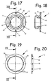
- a hollow screw 4 is provided, as they in particular FIGS. 17 and 18 the drawing can be seen.
- the hollow screw 4 has a thread 41 on the outer casing, which corresponds to the internal thread 1110 on the nozzle 111.
- On the inner wall of the hollow screw 4 three symmetrically arranged locking lugs 40, which extend radially inwardly formed, and which correspond approximately to the tooth gaps of the ring gear 1000 in cross section.
- the hollow screw 4 has a radially outwardly projecting annular flange 42, at the downstream end face symmetrically formed recesses 43 are recessed for the approach of a turning tool.
- a sliding ring 5 of good sliding, wear-resistant plastic as in particular FIGS. 19 and 20 can be seen.
- the two Slide rings 5 have on the inner wall axial slots 50 which correspond to the axial ribs 1112 on the outer surface of the nozzle 111, so that the sliding rings are axially displaceable, but rotatably held on the nozzle 111.
- the hand shower described above can be mounted in the following manner: First, the lever 6 is clipped on the water guide 10 in the pivot bearing 13. Then, the completed water guide 10 is inserted into the housing 19 from the downstream side until the annular flange 120 rests against the end face of the housing 19 and the water guide 10 upstream in the region of the connecting piece 14 with the housing 19 is locked, so that the water guide 10 axially is held fixed in the housing 19. Following this, a slide ring 5 is slid axially onto the neck 111 until it rests against the axial bearing 110. Then, the outer housing 21 is pushed with the bearing flange 210 on the nozzle 111 until it rests against the sliding ring 5.
- the second seal ring 5 is pushed axially on the nozzle 111 until it rests against the downstream end face of the bearing flange 210.
- the hollow screw 4 is screwed into the internal thread 1110, wherein the locking lugs 40 slide on the ring gear 1000 along and deflect the radially projecting teeth resiliently.
- the outer housing 21 rests with an end face with little play on the annular flange 120 to the water guide 10 and forms a certain distance from the housing 19, as it in particular FIG. 3 the drawing can be seen.
- the in FIGS. 13 and 14 the drawing shown water guide housing 20 inserted into the outer housing 21, wherein the tubular pin 200, provided with the sealing ring 201, is inserted into the sleeve piece 100.
- the sealing ring 201 thereby comes sealingly against the inner wall of the sleeve piece 100 to the plant.
- the water guide housing 20 is connected to the two screws 7 with the outer housing 21, as it in particular FIG. 8 the drawing can be seen.
- the bottom part 22, which has a connection piece for the water guide housing 20 on the inside is then mounted.
- the hand shower with the fitting 14 can be connected to a hose and used.
- the shower head 2 can be easily rotated to the holding part 1 about the axis 3, as soon as the claw 61 is pivoted out of a detent recess 2110 by pressing the button 62. In the desired rotational position then the claw can be swung back by means of the spring 60 in the locking position.
Landscapes
- Nozzles (AREA)
- Bathtubs, Showers, And Their Attachments (AREA)
- Domestic Plumbing Installations (AREA)
- Massaging Devices (AREA)
- Percussion Or Vibration Massage (AREA)
- Joints Allowing Movement (AREA)
Description
- Die Erfindung betrifft eine Brause, insbesondere Handbrause, mit einem an einem Halteteil um eine Achse drehbar angeordneten Brausekopf.
- Eine derartige Brause ist aus der deutschen Offenlegungsschrift
DE 100 63 956 A1 bekannt. - Weiterhin ist aus der
DE 297 09 441 U1 eine drehbare Verbindung zwischen einer Sanitärarmatur und einem Brauseschlauch bekannt. - Der Erfindung liegt die Aufgabe zugrunde eine andere drehbare Befestigung des Brausekopfes am Halteteil vorzuschlagen.
- Diese Aufgabe wird erfindungsgemäß dadurch gelöst, dass der Brausekopf ein mit einem Außengehäuse verbundenes Wasserführungsgehäuse aufweist, als Drehgelenk für die Wasserführung ein Rohrzapfen in einem Muffenstück gedichtet angeordnet und zur axialen Sicherung ein koaxial zum Rohrzapfen und dem Muffenstück ausgebildeter Lagerflansch vorgesehen ist, wobei der Lagerflansch an dem Außengehäuse vorgesehen ist und einerseits an einem Axiallager und andererseits an einem Flansch einer koaxial zum Axiallager angeordneten Hohlschraube anliegt.
Weitere Ausgestaltungen der Erfindung sind in den Ansprüchen 2 bis 17 angegeben. - Mit den erfindungsgemäßen Maßnahmen wird insbesondere erreicht, dass das Drehgelenk zwischen dem Brausekopf und dem Halteteil für eine relativ lange Gebrauchsdauer mit der erforderlichen Leichtgängigkeit und im Wesentlichen spielfrei einstellbar ist. Hierbei kann das Halteteil sowohl als Handgriff für eine Handbrause als auch als Träger für eine Stationärbrause ausgebildet sein. Die Drehachse kann vorzugsweise sowohl zum Halteteil, als auch zur Richtung der aus dem Brausekopf austretenden Brausestrahlen geneigt angeordnet werden, so dass der Strahlwinkel der Brausestrahlen zum Tragkörper veränderbar ist.
- In weiterer Ausgestaltung der Erfindung kann der Rohrzapfen vorteilhaft an einem Wasserführungsgehäuse des Brausekopfes angeformt werden, während der Lagerflansch in einem, mittels einer oder mehrerer Schrauben, am Wasserführungsgehäuse befestigbaren Außengehäuse ausgebildet ist, wobei mit einem die Wasseraustrittsöffnungen für die Brausestrahlen aufweisenden Bodenteil sowohl das Außengehäuse als auch das Wasserführungsgehäuse stromabwärts verschlossen wird.
Das an einer rohrförmigen Wasserführung ausgebildete Muffenstück weist vorteilhaft konzentrisch zum Muffenstück einen weiteren Stutzen mit einem größeren Durchmesser auf, an dessen Außenmantel ein Axiallager für den Lagerflansch und an der Innenwandung eine Innengewinde für die Aufnahme der Hohlschraube, die einen entsprechenden radial vorstehenden Ringflansch aufweist, ausgebildet ist, so dass bei der Zusammenmontage durch ein Einschrauben der Hohlschraube auf Block und ein anschließendes definiertes Rückdrehen die Leichtgängigkeit des Drehgelenkes eingestellt werden kann. Hierbei kann zweckmäßig am Muffenstück ein stromabwärts vorstehender, einstückig an dem Muffenstück angeformter elastischer Zahnkranz ausgebildet werden, in den die Hohlschraube mit an der Innenwandung der Hohlschraube radial vorstehenden Rastnasen einfasst, so dass die jeweils eingestellte Drehstellung der Hohlschraube von dem Zahnkranz drehgesichert wird. - In Weiterbildung der Erfindung hat es sich als besonders vorteilhaft herausgestellt, wenn der Lagerflansch des Wasserführungsgehäuses mit seinen beiden Stirnseiten jeweils an einem Gleitring anliegt. Dabei sind zweckmäßig beide Gleitringe mit Axialschlitzen versehen, die an der Außenwandung eines konzentrisch zum Axiallager vorstehenden Stutzens in entsprechend an dem Stutzen ausgebildeten Axialrippen einfassen, so dass sie drehfest zur Wasserführung gehalten werden, in denen dann der Lagerflansch entsprechend drehbar ist. Hierdurch wird insbesondere auch sichergestellt, dass durch den Drehvorgang des Brausekopfes keinerlei Drehmoment auf die Hohlschraube übertragen und somit ein unerwünschtes Mitdrehen der Hohlschraube ausgeschlossen wird.
- In Weiterbildung der Erfindung kann zweckmäßig im Bereich des Halteteiles ein Feststellmittel vorgesehen sein, mit dem die jeweils gewünschte Drehstellung des Brauskopfes zum Halteteil fixierbar ist. Zweckmäßig kann hierzu am Außengehäuse konzentrisch zum Lagerflansch eine im Durchmesser größere Ringfläche ausgebildet sein, an der durch Reibschluss oder Formschluss mit dem Feststellmittel die Drehstellung fixiert werden kann. Vorteilhaft kann hierbei als Feststellmittel ein einarmiger Hebel in einem Drehlager an der Wasserführung angeordnet werden, der von einer Feder gegen die kreisförmige Fläche des Brausekopfes gedrückt ist, so dass vom Benutzer durch Überwindung der Federkraft das Feststellmittel gelöst, der Brausekopf in die gewünschte Drehstellung gebracht und anschließend durch ein Loslassen des Hebels die gewählte Drehstellung wieder fixiert wird. Zweckmäßig kann hierbei der Hebel eine Klaue aufweisen, die in entsprechende Rastmulden der kreisförmigen Fläche einfasst.
Schließlich kann vorteilhaft die rohrförmige Wasserführung in einem Gehäuse angeordnet werden, wobei der stromaufwärts gelegene Endbereich der Wasserführung aus dem Gehäuse vorsteht, so dass eine Leitung für die Wasserzuführung anschließbar ist. Am stromabwärts gelegenen Endbereich kann das Gehäuse mit einem konzentrisch zum Muffenstück angeformten äußeren Ringflansch stirnseitig verschlossen werden. Mit Hilfe dieses äußeren Ringflansches kann außerdem erreicht werden, dass die meist veredelten Oberflächen des Gehäuses und des Außengehäuses des Brausekopfes mit einem bestimmten Abstand zueinander in der Montagelage angeordnet werden können, so dass sicher eine Kontaktkorrosion ausgeschlossen und ein harmonischer Übergang sichergestellt ist. - Ein Ausführungsbeispiel der Erfindung ist in der Zeichnung dargestellt und wird im Folgenden näher beschrieben. Es zeigt in der Zeichnung
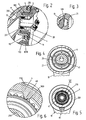
- Figur 1
- eine Handbrause in Seitenansicht, teilweise geschnitten;
- Figur 2
- einen in
Figur 1 gezeigten Teilbereich II in vergrößerter Darstellung; - Figur 3
- einen in
Figur 1 gezeigten Teilbereich III in vergrößerter Darstellung; - Figur 4
- die in
Figur 1 gezeigte Handbrause in der Schnittebene IV; - Figur 5
- die in
Figur 1 gezeigte Handbrause in der Schnittebene V; - Figur 6
- einen in
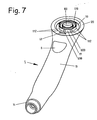
Figur 5 angegebenen Teilbereich VI in vergrößerter Darstellung; - Figur 7
- den in
Figur 1 gezeigten Halteteil der Handbrause in Perspektivansicht; - Figur 8
- den in
Figur 1 gezeigten Brausekopf ohne Bodenteil in Perspektivansicht; - Figur 9
- den in
Figur 8 gezeigten Teil des Brausekopfes um etwa 90° gedreht in Perspektivansicht; - Figur 10
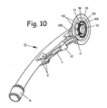
- die in
Figur 1 gezeigte Wasserführung in Perspektivansicht; - Figur 11
- die in
Figur 10 gezeigte Wasserführung in der Schnittebene XI derFigur 12 ; - Figur 12
- die in
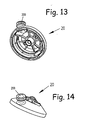
Figur 11 gezeigte Wasserführung um 90° gedreht; - Figur 13
- das in
Figur 1 zum Teil gezeigte Wasserführungsgehäuse in Perspektivansicht; - Figur 14
- das in
Figur 13 gezeigte Wasserführungsgehäuse um etwa 90° gedreht in Perspektivansicht; - Figur 15
- das in
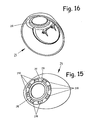
Figur 1 gezeigte Außengehäuse des Brausekopfes in Perspektivansicht; - Figur 16
- das in
Figur 15 gezeigte Außengehäuse um etwa 90° gedreht in Perspektivansicht; - Figur 17
- die in
Figur 1 gezeigte Hohlschraube in Draufsicht in vergrößerter Darstellung; - Figur 18
- die in
Figur 17 gezeigte Hohlschraube in der Schnitteben XVIII; - Figur 19
- einen in
Figur 1 gezeigten Gleitring in Draufsicht in vergrößerter Darstellung; - Figur 20
- den in
Figur 19 gezeigten Gleitring in der Schnittebene XX. - Die in der Zeichnung dargestellte Handbrause enthält im Wesentlichen einen Halteteil 1 und einen Brausekopf 2. Der Brausekopf 2 ist dabei um eine Achse 3 drehbar am Halteteil 1 angelenkt. Die Achse 3 ist sowohl zur Längsachse des Halteteiles als auch zur zentralen Längsachse der aus Wasseraustrittsöffnungen 220 aus dem Brausekopf 2 austretenden Brausestrahlen geneigt angeordnet. Durch diese Anlenkung kann der Strahlwinkel des Brausekopfes zum Halteteil 1 in Abhängigkeit der Drehstellung verändert werden.
- Der Halteteil 1 besteht aus einer rohrförmigen Wasserführung 10 und einem als Handgriff ausgebildeten Gehäuse 19. Die Wasserführung 10 durchgreift hierbei das Gehäuse 19 und steht am stromaufwärts gelegenen Endbereich mit einem Anschlussstück 14 aus dem Gehäuse 19 vor. An das Anschlussstück 14 kann eine in der Zeichnung nicht dargestellte Leitung zur Heranführung von Brausewasser angeschlossen werden. Außerdem ist die Wasserführung 10 am stromaufwärts gelegenen Ende axial zum Gehäuse 19 fixiert. Am gegenüberliegenden Endbereich ist koaxial zur Drehachse 3 ein Muffenstück 100 ausgebildet. Am stromabwärts gelegenen Endbereich des Muffenstückes 100 ist ein Zahnkranz 1000 angeformt, an dessen Außenmantel eine Verzahnung ausgebildet ist. Koaxial zum Muffenstück 100 ist ein, einen größeren Durchmesser aufweisender Stutzen 111 an der Wasserführung 10 angeformt, der an seiner Innenwandung ein Innengewinde und an seinem Außenmantel ein als Ringflansch ausgebildetes Axiallager 110 trägt. Am Stutzen 111 sind stromabwärts hinter dem Axiallager 110 am Außenmantel radial vorstehende Axialrippen 1112 angeformt, die symmetrisch auf den Umfang verteilt sind. Konzentrisch zum Stutzen 111 ist außerdem an einer kegelförmigen Ausbildung ein weiterer Ringflansch 120 ausgebildet, der an der Stirnseite des Gehäuses 19 anliegt.
- In einem Raum 190 zwischen dem Gehäuse 19 und der Wasserführung 10 ist ein Hebel 6 angeordnet. Der Hebel 6 ist einarmig ausgebildet und von einem an der Wasserführung 10 angeformten Drehlager 13 aufgenommen. Das Drehlager 13 ist dabei so ausgebildet, dass der Hebel in der Lagerposition mit seinen Drehzapfen in das Drehlager 13 einsprengbar ist. Der Hebel 6 ist an dem zum Drehlager 13 entgegengesetzten Endbereich mit einer Klaue 61 versehen, die durch eine Öffnung 1200 des Ringflansches 120 hindurchgreift. Außerdem weist der Hebel 6 etwa auf der halben Hebellänge eine radial durch eine Öffnung 191 im Gehäuse 19 hindurchgreifende Taste 62 auf. An der der Taste 62 gegenüberliegenden Seite des Hebels 6 ist eine Feder 60 in Form einer Biegelasche angeformt, die sich mit ihrem Endbereich an der Wasserführung 10 abstützt. Die Öffnung 191 in dem Gehäuse 19 ist an einer Außenseite mit einer Membran 8 abgedeckt, so dass über die Öffnung 191 keinerlei Stoffe von außen in den Raum 190 eindringen können.
- Der Brausekopf 2 weist ein etwa kugelförmiges Außengehäuse 21 auf, das stromabwärts von einem Bodenteil 22 mit den Wasseraustrittsöffnungen 220 abgeschlossen ist. Stromaufwärts weist das Außengehäuse 21 eine von einem Lagerflansch 210 umschlossene Öffnung auf, in der konzentrisch zur Lagerfläche 210 ein Rohrzapfen 200 eines Wasserführungsgehäuses 20 angeordnet ist. Auf dem Außenmantel des Rohrzapfens 200 ist in einer Ringnut ein Dichtring 201 angeordnet. Das Wasserführungsgehäuse 20 ist dabei so ausgebildet, dass es in der Stecklage, in der der Rohrzapfen 200 konzentrisch zum Lagerflansch 210 angeordnet ist, mit zwei diagonal gegenüberliegenden Schrauben 7 am Außengehäüse 21 fixierbar ist, wie es insbesondere aus
Figur 8 und 9 der Zeichnung zu entnehmen ist. Der Bodenteil 22 ist dabei so ausgebildet, dass einerseits ein harmonischer Übergang zum Außengehäuse 21 und andererseits ein dichter Anschluss an das Wasserführungsgehäuse 20 nach der Zusammenmontage hergestellt wird.
An der dem Muffenstück 100 zugekehrten Stirnseite des Außengehäuses 21 ist konzentrisch zum Lagerflansch 210 eine einen größeren Durchmesser aufweisende kreisförmige Fläche 211 ausgebildet, in der symmetrisch angeordnete Rastmulden 2110 eingelassen sind. - Zur Axialsicherung des Drehgelenkes ist außerdem eine Hohlschraube 4 vorgesehen, wie sie insbesondere aus
Figur 17 und 18 der Zeichnung zu entnehmen ist. Die Hohlschraube 4 hat am Außenmantel ein Gewinde 41, das dem Innengewinde 1110 am Stutzen 111 entspricht. An der Innenwandung der Hohlschraube 4 sind drei symmetrisch angeordnete Rastnasen 40, die sich radial nach innen erstrecken, angeformt und die in etwa im Querschnitt den Zahnlücken des Zahnkranzes 1000 entsprechen. Am stromabwärts gelegenen Endbereich weist die Hohlschraube 4 einen radial nach außen vorstehenden Ringflansch 42 auf, an dessen stromabwärts gelegenen Stirnseite symmetrisch ausgebildete Ausnehmungen 43 für den Ansatz eines Drehwerkzeuges eingelassen sind. Außerdem sind an der stromabwärts gelegenen Stirnseite des Axiallagers 110 und an der stromaufwärts gelegenen Stirnseite des Ringflansches 42 der Hohlschraube 4 jeweils ein Gleitring 5 aus gut gleitfähigem, verschleißfestem Kunststoff vorgesehen, wie es insbesondere ausFigur 19 und 20 zu entnehmen ist. Die beiden Gleitringe 5 weisen dabei an der Innenwandung Axialschlitze 50 auf, die den Axialrippen 1112 am Außenmantel des Stutzens 111 entsprechen, so dass die Gleitringe axial verschieblich, aber drehfest auf dem Stutzen 111 gehalten sind. - Die vorstehend beschriebene Handbrause kann in folgender Weise montiert werden:
Zunächst wird der Hebel 6 an der Wasserführung 10 in das Drehlager 13 eingeklippst. Sodann wird die komplettierte Wasserführung 10 in das Gehäuse 19 von der stromabwärts gelegenen Seite eingeführt, bis der Ringflansch 120 an der Stirnseite des Gehäuses 19 anliegt und die Wasserführung 10 stromaufwärts im Bereich des Anschlussstückes 14 mit dem Gehäuse 19 verrastet, so dass die Wasserführung 10 axial festliegend im Gehäuse 19 gehalten ist. Im Anschluss daran wird auf den Stutzen 111 ein Gleitring 5 axial bis zur Anlage an das Axiallager 110 aufgeschoben. Sodann wird das Außengehäuse 21 mit dem Lagerflansch 210 auf den Stutzen 111 bis zur Anlage an den Gleitring 5 aufgeschoben. Anschließend wird der zweite Gleitring 5 axial auf den Stutzen 111 bis zur Anlage an der stromabwärts gelegenen Stirnseite des Lagerflansches 210 aufgeschoben. Sodann wird die Hohlschraube 4 in das Innengewinde 1110 eingeschraubt, wobei die Rastnasen 40 am Zahnkranz 1000 entlang gleiten und die radial vorstehenden Zähnen elastisch federnd auslenken. Sobald der Lagerflansch 210 mit den beiden Gleitringen 5 von der Hohlschraube 4 auf Block gegen das Axiallager 110 gedrückt ist, wird die Hohlschraube 4 um einen vorgegebenen Drehwinkel zurückgedreht, so dass die erforderliche Leichtgängigkeit des Drehgelenkes sichergestellt ist. - In dieser Lage liegt das Außengehäuse 21 mit einer Stirnseite mit geringem Spiel am Ringflansch 120 an der Wasserführung 10 an und bildet einen bestimmten Abstand zum Gehäuse 19, wie es insbesondere aus
Figur 3 der Zeichnung zu entnehmen ist.
Hiernach wird das inFigur 13 und 14 der Zeichnung dargestellte Wasserführungsgehäuse 20 in das Außengehäuse 21 eingeführt, wobei der Rohrzapfen 200, mit dem Dichtring 201 versehen, in das Muffenstück 100 eingeführt wird. Der Dichtring 201 gelangt dabei dichtend an der Innenwandung des Muffenstückes 100 zur Anlage. In der Stecklage wird das Wasserführungsgehäuse 20 mit den beiden Schrauben 7 mit dem Außengehäuse 21 verbunden, wie es insbesondere ausFigur 8 der Zeichnung zu entnehmen ist.
Im Anschluss daran wird dann der Bodenteil 22, der an der Innenseite ein Anschlussstück für das Wasserführungsgehäuse 20 aufweist, anmontiert. - Hiernach kann die Handbrause mit dem Anschlussstück 14 an eine Schlauchleitung angeschlossen und benutzt werden.
Der Brausekopf 2 kann zum Halteteil 1 um die Achse 3 leichtgängig gedreht werden, sobald die Klaue 61 aus einer Rastmulde 2110 durch Eindrücken der Taste 62 herausgeschwenkt ist. In der gewünschten Drehstellung kann dann die Klaue mit Hilfe der Feder 60 in die Rastposition zurückgeschwenkt werden.
Claims (17)
- Brause, insbesondere Handbrause,- mit einem an einem Halteteil (1) um eine Achse (3) drehbar angeordneten Brausekopf (2),dadurch gekennzeichnet, dass- der Brausekopf (2) ein mit einem Außengehäuse (21) verbundenes Wasserführungsgehäuse (20) aufweist,- als Drehgelenk für die Wasserführung ein Rohrzapfen (200) in einem Muffenstück (100) gedichtet angeordnet und- zur axialen Sicherung des Drehgelenks ein koaxial zum Rohrzapfen (200) und dem Muffenstück (100) ausgebildeter Lagerflansch (210) vorgesehen ist, wobei- - - der Lagerflansch (210) an dem Außengehäuse vorgesehen ist und einerseits an einem Axiallager (110) und- - - andererseits an einem Ringflansch (42) einer koaxial zum Axiallager (110) angeordneten Hohlschraube (4) anliegt.
- Brause nach Anspruch 1, dadurch gekennzeichnet, dass die Achse (3) sowohl zum Halteteil (1) als auch zum Wasseraustrittsbereich des Brausekopfes (2) geneigt angeordnet ist.
- Brause nach Anspruch 1 oder 2, dadurch gekennzeichnet, dass der Rohrzapfen (200) an dem Wasserführungsgehäuse (20) angeformt ist.
- Brause nach Anspruch 1 oder 2, dadurch gekennzeichnet, dass das Wasserführungsgehäuse (20) mit wenigstens einer Schraube (7) am Außengehäuse (21) lösbar befestigt ist.
- Brause nach wenigstens einem der vorhergehenden Ansprüche, dadurch gekennzeichnet, dass das Muffenstück (100) an einer Wasserführung (10) ausgebildet ist, an der konzentrisch zum Muffenstück (100) ein weiterer Stutzen (111) mit einem größeren Durchmesser angeformt ist, der mit einem Innengewinde versehen ist und der am Außenmantel ein Axiallager (110) trägt, wobei in das Innengewinde (1110) die Hohlschraube (4) eindrehbar ist.
- Brause nach Anspruch 5, dadurch gekennzeichnet, dass stromabwärts vom Axiallager (110) am vorstehenden Bereich des Stutzens (111) am Außenmantel radial vorstehende Axialrippen (1112) angeformt sind, auf die zwei Gleitringe (5) mit entsprechenden Axialschlitzen (50) anordbar sind, welche nach dem Eindrehen der Hohlschraube (4) ein Gleitlager für den Lagerflansch (210) bilden.
- Brause nach wenigstens einem der vorhergehenden Ansprüche, dadurch gekennzeichnet, dass die Hohlschraube (4) an der Innenwandung wenigstens eine radial vorstehende Rastnase (40) aufweist, die jeweils in der Schraubposition in einen am Muffenstück (100) angeformten, federnden Zahnkranz (1000) einfasst und eine Drehsicherung für die Hohlschraube (4) bildet.
- Brause nach wenigstens einem der vorhergehenden Ansprüche, dadurch gekennzeichnet, dass am stromabwärts gelegenen Endbereich der Wasserführung (10) konzentrisch zum Muffenstück (100) ein weiterer Ringflansch (120) angeformt ist, der einerseits die Stirnseite des Gehäuses (19) verschließt und andererseits einen bestimmten Abstand zum Gehäuse (19) wahrende Anlagefläche für das Außengehäuse (21) des Brausekopfes (2) bildet.
- Brause nach wenigstens einem der vorhergehenden Ansprüche, dadurch gekennzeichnet, dass konzentrisch zum Lagerflansch (210) am Außengehäuse (21) eine kreisringförmige Fläche (211) ausgebildet ist, an die ein lösbares Feststellmittel angedrückt ist, so dass der Brausekopf (2) in der jeweils gewünschten Drehstellung zum Gehäuse (19) feststellbar ist.
- Brause nach Anspruch 9, dadurch gekennzeichnet, dass in der Fläche (211) Rastmulden (2110) eingeformt sind, in die das Feststellmittel zur Verrastung einfasst.
- Brause nach Anspruch 9 oder 10 dadurch gekennzeichnet, dass als Feststellmittel ein von einer Feder (60) in die Feststellposition gedrückter Hebel (6) vorgesehen ist.
- Brause nach Anspruch 11, dadurch gekennzeichnet, dass der Hebel (6) eine zu den Rastmulden (2110) entsprechende Klaue (61) hat.
- Brause nach Anspruch 11 oder 12, dadurch gekennzeichnet, dass der Hebel (6) einarmig ausgebildet und an der Wasserführung (10) mit einem Drehlager (13) befestigt ist.
- Brause nach wenigstens einem der vorhergehenden Ansprüche, dadurch gekennzeichnet, dass die Feder (60) als Blattfeder einstückig am Hebel (6) ausgebildet ist.
- Brause nach wenigstens einem der vorhergehenden Ansprüche, dadurch gekennzeichnet, dass der Hebel (6) mit der Feder (60) in einem Raum (190) zwischen der Wasserführung (10) und dem Gehäuse (19) angeordnet ist und mit einer Taste (62) durch eine Öffnung (191) des Gehäuses (19) hindurchtritt.
- Brause nach Anspruch 15, dadurch gekennzeichnet, dass die Öffnung (191) im Gehäuse (19) von einer Membran (8) abgedeckt ist.
- Brause nach wenigstens einem der vorhergehenden Ansprüche, dadurch gekennzeichnet, dass die Klaue (61) durch eine Öffnung (1200) im Ringflansch (120) vom Raum (190) zur Fläche (211) hindurch greift.
Applications Claiming Priority (2)
| Application Number | Priority Date | Filing Date | Title |
|---|---|---|---|
| DE10307122A DE10307122A1 (de) | 2003-02-19 | 2003-02-19 | Brause |
| DE10307122 | 2003-02-19 |
Publications (2)
| Publication Number | Publication Date |
|---|---|
| EP1449591A1 EP1449591A1 (de) | 2004-08-25 |
| EP1449591B1 true EP1449591B1 (de) | 2008-07-02 |
Family
ID=32731059
Family Applications (1)
| Application Number | Title | Priority Date | Filing Date |
|---|---|---|---|
| EP04002734A Expired - Lifetime EP1449591B1 (de) | 2003-02-19 | 2004-02-07 | Brause |
Country Status (5)
| Country | Link |
|---|---|
| EP (1) | EP1449591B1 (de) |
| CN (1) | CN1524480A (de) |
| AT (1) | ATE399595T1 (de) |
| DE (2) | DE10307122A1 (de) |
| ES (1) | ES2309405T3 (de) |
Families Citing this family (4)
| Publication number | Priority date | Publication date | Assignee | Title |
|---|---|---|---|---|
| EP2301669A1 (de) | 2008-10-04 | 2011-03-30 | Kwc Ag | Brause mit beleuchtetem Brausekopf |
| DE502008002491D1 (de) | 2008-10-04 | 2011-03-10 | Kwc Ag | Umstellbarer Brausekopf |
| CN103637728A (zh) * | 2013-12-03 | 2014-03-19 | 夏致俊 | 全自动洗澡淋浴房的洗涤力调节装置 |
| DE102023124265A1 (de) * | 2023-09-08 | 2025-03-13 | Hansgrohe Se | Brause mit Mengenzuschalteinrichtung |
Family Cites Families (5)
| Publication number | Priority date | Publication date | Assignee | Title |
|---|---|---|---|---|
| US2144644A (en) * | 1936-03-17 | 1939-01-24 | Lawrence T Ward | Spray head |
| DE7533417U (de) * | 1975-10-21 | 1976-02-12 | Max Langenstein Feld- Und Gartengeraete, 7918 Illertissen | Schlauchwagen |
| DE2819623C3 (de) * | 1978-05-05 | 1981-07-16 | Hans Grohe Gmbh & Co Kg, 7622 Schiltach | Brausevorrichtung |
| DE29709441U1 (de) * | 1997-05-29 | 1997-07-24 | Friedhelm Ramspott Metall- und Kunststoffverarbeitung GmbH & Co KG, 59909 Bestwig | Drehbare Verbindung für Sanitärarmaturen |
| US6508415B2 (en) * | 2001-05-16 | 2003-01-21 | Wang Tzu-Meng | Spray head with a pivot nozzle |
-
2003
- 2003-02-19 DE DE10307122A patent/DE10307122A1/de not_active Withdrawn
-
2004
- 2004-02-07 ES ES04002734T patent/ES2309405T3/es not_active Expired - Lifetime
- 2004-02-07 EP EP04002734A patent/EP1449591B1/de not_active Expired - Lifetime
- 2004-02-07 DE DE502004007463T patent/DE502004007463D1/de not_active Expired - Lifetime
- 2004-02-07 AT AT04002734T patent/ATE399595T1/de not_active IP Right Cessation
- 2004-02-18 CN CNA2004100046092A patent/CN1524480A/zh active Pending
Also Published As
| Publication number | Publication date |
|---|---|
| ATE399595T1 (de) | 2008-07-15 |
| DE502004007463D1 (de) | 2008-08-14 |
| CN1524480A (zh) | 2004-09-01 |
| ES2309405T3 (es) | 2008-12-16 |
| DE10307122A1 (de) | 2004-09-02 |
| EP1449591A1 (de) | 2004-08-25 |
Similar Documents
| Publication | Publication Date | Title |
|---|---|---|
| DE602004003306T2 (de) | Handsprühgerät mit einer Schnelltrennkupplung | |
| EP1320647A1 (de) | Brausevorrichtung | |
| DE29521612U1 (de) | Umlenkventil für Duschsprühvorrichtungen | |
| EP0933136A2 (de) | Wasserausflussarmatur | |
| DE19637074A1 (de) | Kupplungseinrichtung zur Verbindung zweier Rohrelemente | |
| EP2292850A2 (de) | Kugelgelenk für eine sanitäre Auslaufarmatur | |
| DE2827847A1 (de) | Steckverbindung, insbesondere fuer sanitaergegenstaende | |
| DE29914962U1 (de) | Luftauslaß, insbesondere für eine Kraftfahrzeug-Lüftung | |
| EP0733839B1 (de) | Mischventil mit einem Handhebel | |
| EP1246974A1 (de) | Brausehaltevorrichtung | |
| EP0757134A1 (de) | Mischbatterie | |
| EP0818647B1 (de) | Mischventil mit einem Handhebel | |
| EP3759285B9 (de) | Kugelgelenk | |
| EP1686218B1 (de) | Sanitärarmatur mit schwenkbarem Wasserauslass | |
| EP1449591A1 (de) | Brause | |
| DE10232463A1 (de) | Handbrause mit integriertem Ventil | |
| DE102004018749B4 (de) | Auslaufelement für eine Sanitärarmatur | |
| EP0804970B1 (de) | Handspritzpistole für ein Hochdruckreinigungsgerät | |
| DE20002216U1 (de) | Anschluss eines Ablaufrohrs an einen Überputzspülkasten der Toilette | |
| DE102005052919A1 (de) | Mischbatterie | |
| DE2634721A1 (de) | Hydraulisches dreiwegeventil, insbesondere wasseranschluss fuer mund- und/ oder hautmassage- bzw. hautreinigungsduschen | |
| DE10307072A1 (de) | Brause mit Umstelleinrichtung | |
| DE102004037051A1 (de) | Mischbatterie mit Standanschluss | |
| DE1708634A1 (de) | Laermgedaempftes Ventilsystem fuer Klosettdruckspuelvorrichtung mit Ruecksaugesicherung | |
| DE3912278C2 (de) |
Legal Events
| Date | Code | Title | Description |
|---|---|---|---|
| PUAI | Public reference made under article 153(3) epc to a published international application that has entered the european phase |
Free format text: ORIGINAL CODE: 0009012 |
|
| AK | Designated contracting states |
Kind code of ref document: A1 Designated state(s): AT BE BG CH CY CZ DE DK EE ES FI FR GB GR HU IE IT LI LU MC NL PT RO SE SI SK TR |
|
| AX | Request for extension of the european patent |
Extension state: AL LT LV MK |
|
| 17P | Request for examination filed |
Effective date: 20041009 |
|
| AKX | Designation fees paid |
Designated state(s): AT BE BG CH CY CZ DE DK EE ES FI FR GB GR HU IE IT LI LU MC NL PT RO SE SI SK TR |
|
| RAP1 | Party data changed (applicant data changed or rights of an application transferred) |
Owner name: GROHE AG |
|
| 17Q | First examination report despatched |
Effective date: 20061109 |
|
| GRAP | Despatch of communication of intention to grant a patent |
Free format text: ORIGINAL CODE: EPIDOSNIGR1 |
|
| GRAS | Grant fee paid |
Free format text: ORIGINAL CODE: EPIDOSNIGR3 |
|
| GRAA | (expected) grant |
Free format text: ORIGINAL CODE: 0009210 |
|
| AK | Designated contracting states |
Kind code of ref document: B1 Designated state(s): AT BE BG CH CY CZ DE DK EE ES FI FR GB GR HU IE IT LI LU MC NL PT RO SE SI SK TR |
|
| REG | Reference to a national code |
Ref country code: GB Ref legal event code: FG4D Free format text: NOT ENGLISH |
|
| REG | Reference to a national code |
Ref country code: CH Ref legal event code: EP |
|
| REF | Corresponds to: |
Ref document number: 502004007463 Country of ref document: DE Date of ref document: 20080814 Kind code of ref document: P |
|
| REG | Reference to a national code |
Ref country code: IE Ref legal event code: FG4D Free format text: LANGUAGE OF EP DOCUMENT: GERMAN |
|
| PG25 | Lapsed in a contracting state [announced via postgrant information from national office to epo] |
Ref country code: SI Free format text: LAPSE BECAUSE OF FAILURE TO SUBMIT A TRANSLATION OF THE DESCRIPTION OR TO PAY THE FEE WITHIN THE PRESCRIBED TIME-LIMIT Effective date: 20080702 |
|
| PG25 | Lapsed in a contracting state [announced via postgrant information from national office to epo] |
Ref country code: NL Free format text: LAPSE BECAUSE OF FAILURE TO SUBMIT A TRANSLATION OF THE DESCRIPTION OR TO PAY THE FEE WITHIN THE PRESCRIBED TIME-LIMIT Effective date: 20080702 |
|
| REG | Reference to a national code |
Ref country code: ES Ref legal event code: FG2A Ref document number: 2309405 Country of ref document: ES Kind code of ref document: T3 |
|
| NLV1 | Nl: lapsed or annulled due to failure to fulfill the requirements of art. 29p and 29m of the patents act | ||
| PG25 | Lapsed in a contracting state [announced via postgrant information from national office to epo] |
Ref country code: PT Free format text: LAPSE BECAUSE OF FAILURE TO SUBMIT A TRANSLATION OF THE DESCRIPTION OR TO PAY THE FEE WITHIN THE PRESCRIBED TIME-LIMIT Effective date: 20081202 |
|
| REG | Reference to a national code |
Ref country code: IE Ref legal event code: FD4D |
|
| PG25 | Lapsed in a contracting state [announced via postgrant information from national office to epo] |
Ref country code: FI Free format text: LAPSE BECAUSE OF FAILURE TO SUBMIT A TRANSLATION OF THE DESCRIPTION OR TO PAY THE FEE WITHIN THE PRESCRIBED TIME-LIMIT Effective date: 20080702 Ref country code: BG Free format text: LAPSE BECAUSE OF FAILURE TO SUBMIT A TRANSLATION OF THE DESCRIPTION OR TO PAY THE FEE WITHIN THE PRESCRIBED TIME-LIMIT Effective date: 20081002 |
|
| PG25 | Lapsed in a contracting state [announced via postgrant information from national office to epo] |
Ref country code: EE Free format text: LAPSE BECAUSE OF FAILURE TO SUBMIT A TRANSLATION OF THE DESCRIPTION OR TO PAY THE FEE WITHIN THE PRESCRIBED TIME-LIMIT Effective date: 20080702 Ref country code: DK Free format text: LAPSE BECAUSE OF FAILURE TO SUBMIT A TRANSLATION OF THE DESCRIPTION OR TO PAY THE FEE WITHIN THE PRESCRIBED TIME-LIMIT Effective date: 20080702 Ref country code: IE Free format text: LAPSE BECAUSE OF FAILURE TO SUBMIT A TRANSLATION OF THE DESCRIPTION OR TO PAY THE FEE WITHIN THE PRESCRIBED TIME-LIMIT Effective date: 20080702 |
|
| PGFP | Annual fee paid to national office [announced via postgrant information from national office to epo] |
Ref country code: ES Payment date: 20090219 Year of fee payment: 6 |
|
| PLBE | No opposition filed within time limit |
Free format text: ORIGINAL CODE: 0009261 |
|
| STAA | Information on the status of an ep patent application or granted ep patent |
Free format text: STATUS: NO OPPOSITION FILED WITHIN TIME LIMIT |
|
| PG25 | Lapsed in a contracting state [announced via postgrant information from national office to epo] |
Ref country code: RO Free format text: LAPSE BECAUSE OF FAILURE TO SUBMIT A TRANSLATION OF THE DESCRIPTION OR TO PAY THE FEE WITHIN THE PRESCRIBED TIME-LIMIT Effective date: 20080702 Ref country code: CZ Free format text: LAPSE BECAUSE OF FAILURE TO SUBMIT A TRANSLATION OF THE DESCRIPTION OR TO PAY THE FEE WITHIN THE PRESCRIBED TIME-LIMIT Effective date: 20080702 Ref country code: SK Free format text: LAPSE BECAUSE OF FAILURE TO SUBMIT A TRANSLATION OF THE DESCRIPTION OR TO PAY THE FEE WITHIN THE PRESCRIBED TIME-LIMIT Effective date: 20080702 |
|
| 26N | No opposition filed |
Effective date: 20090403 |
|
| BERE | Be: lapsed |
Owner name: GROHE A.G. Effective date: 20090228 |
|
| PGFP | Annual fee paid to national office [announced via postgrant information from national office to epo] |
Ref country code: IT Payment date: 20090220 Year of fee payment: 6 |
|
| PG25 | Lapsed in a contracting state [announced via postgrant information from national office to epo] |
Ref country code: MC Free format text: LAPSE BECAUSE OF NON-PAYMENT OF DUE FEES Effective date: 20090228 |
|
| REG | Reference to a national code |
Ref country code: CH Ref legal event code: PL |
|
| GBPC | Gb: european patent ceased through non-payment of renewal fee |
Effective date: 20090207 |
|
| PG25 | Lapsed in a contracting state [announced via postgrant information from national office to epo] |
Ref country code: LI Free format text: LAPSE BECAUSE OF NON-PAYMENT OF DUE FEES Effective date: 20090228 Ref country code: CH Free format text: LAPSE BECAUSE OF NON-PAYMENT OF DUE FEES Effective date: 20090228 |
|
| PGFP | Annual fee paid to national office [announced via postgrant information from national office to epo] |
Ref country code: FR Payment date: 20090213 Year of fee payment: 6 |
|
| PG25 | Lapsed in a contracting state [announced via postgrant information from national office to epo] |
Ref country code: SE Free format text: LAPSE BECAUSE OF FAILURE TO SUBMIT A TRANSLATION OF THE DESCRIPTION OR TO PAY THE FEE WITHIN THE PRESCRIBED TIME-LIMIT Effective date: 20081002 |
|
| PG25 | Lapsed in a contracting state [announced via postgrant information from national office to epo] |
Ref country code: BE Free format text: LAPSE BECAUSE OF NON-PAYMENT OF DUE FEES Effective date: 20090228 |
|
| PG25 | Lapsed in a contracting state [announced via postgrant information from national office to epo] |
Ref country code: GB Free format text: LAPSE BECAUSE OF NON-PAYMENT OF DUE FEES Effective date: 20090207 |
|
| PG25 | Lapsed in a contracting state [announced via postgrant information from national office to epo] |
Ref country code: AT Free format text: LAPSE BECAUSE OF NON-PAYMENT OF DUE FEES Effective date: 20090207 |
|
| PG25 | Lapsed in a contracting state [announced via postgrant information from national office to epo] |
Ref country code: GR Free format text: LAPSE BECAUSE OF FAILURE TO SUBMIT A TRANSLATION OF THE DESCRIPTION OR TO PAY THE FEE WITHIN THE PRESCRIBED TIME-LIMIT Effective date: 20081003 |
|
| REG | Reference to a national code |
Ref country code: FR Ref legal event code: ST Effective date: 20101029 |
|
| PG25 | Lapsed in a contracting state [announced via postgrant information from national office to epo] |
Ref country code: FR Free format text: LAPSE BECAUSE OF NON-PAYMENT OF DUE FEES Effective date: 20100301 |
|
| PG25 | Lapsed in a contracting state [announced via postgrant information from national office to epo] |
Ref country code: IT Free format text: LAPSE BECAUSE OF NON-PAYMENT OF DUE FEES Effective date: 20100207 |
|
| PG25 | Lapsed in a contracting state [announced via postgrant information from national office to epo] |
Ref country code: LU Free format text: LAPSE BECAUSE OF NON-PAYMENT OF DUE FEES Effective date: 20090207 |
|
| PGFP | Annual fee paid to national office [announced via postgrant information from national office to epo] |
Ref country code: DE Payment date: 20110218 Year of fee payment: 8 |
|
| PG25 | Lapsed in a contracting state [announced via postgrant information from national office to epo] |
Ref country code: HU Free format text: LAPSE BECAUSE OF FAILURE TO SUBMIT A TRANSLATION OF THE DESCRIPTION OR TO PAY THE FEE WITHIN THE PRESCRIBED TIME-LIMIT Effective date: 20090103 |
|
| PG25 | Lapsed in a contracting state [announced via postgrant information from national office to epo] |
Ref country code: TR Free format text: LAPSE BECAUSE OF FAILURE TO SUBMIT A TRANSLATION OF THE DESCRIPTION OR TO PAY THE FEE WITHIN THE PRESCRIBED TIME-LIMIT Effective date: 20080702 |
|
| PG25 | Lapsed in a contracting state [announced via postgrant information from national office to epo] |
Ref country code: CY Free format text: LAPSE BECAUSE OF FAILURE TO SUBMIT A TRANSLATION OF THE DESCRIPTION OR TO PAY THE FEE WITHIN THE PRESCRIBED TIME-LIMIT Effective date: 20080702 |
|
| REG | Reference to a national code |
Ref country code: ES Ref legal event code: FD2A Effective date: 20120220 |
|
| PG25 | Lapsed in a contracting state [announced via postgrant information from national office to epo] |
Ref country code: ES Free format text: LAPSE BECAUSE OF NON-PAYMENT OF DUE FEES Effective date: 20100208 |
|
| REG | Reference to a national code |
Ref country code: DE Ref legal event code: R119 Ref document number: 502004007463 Country of ref document: DE Effective date: 20120901 |
|
| PG25 | Lapsed in a contracting state [announced via postgrant information from national office to epo] |
Ref country code: DE Free format text: LAPSE BECAUSE OF NON-PAYMENT OF DUE FEES Effective date: 20120901 |