EP1448113B1 - Komponenten für verbesserte abdrücke - Google Patents
Komponenten für verbesserte abdrücke Download PDFInfo
- Publication number
- EP1448113B1 EP1448113B1 EP02783906.7A EP02783906A EP1448113B1 EP 1448113 B1 EP1448113 B1 EP 1448113B1 EP 02783906 A EP02783906 A EP 02783906A EP 1448113 B1 EP1448113 B1 EP 1448113B1
- Authority
- EP
- European Patent Office
- Prior art keywords
- abutment
- component
- impression
- region
- implant
- Prior art date
- Legal status (The legal status is an assumption and is not a legal conclusion. Google has not performed a legal analysis and makes no representation as to the accuracy of the status listed.)
- Expired - Lifetime
Links
- 230000010485 coping Effects 0.000 claims description 116
- 239000007943 implant Substances 0.000 claims description 85
- 239000000463 material Substances 0.000 claims description 66
- 230000007704 transition Effects 0.000 claims description 15
- 238000006073 displacement reaction Methods 0.000 claims description 9
- 238000004904 shortening Methods 0.000 claims description 5
- 238000007373 indentation Methods 0.000 claims description 4
- 238000000034 method Methods 0.000 description 16
- 239000002131 composite material Substances 0.000 description 15
- 238000002513 implantation Methods 0.000 description 13
- 239000004053 dental implant Substances 0.000 description 12
- 210000001519 tissue Anatomy 0.000 description 10
- 210000000988 bone and bone Anatomy 0.000 description 9
- 238000000465 moulding Methods 0.000 description 9
- 150000001875 compounds Chemical class 0.000 description 7
- 230000008901 benefit Effects 0.000 description 5
- 230000014759 maintenance of location Effects 0.000 description 5
- 239000011796 hollow space material Substances 0.000 description 4
- 238000009434 installation Methods 0.000 description 4
- 230000004048 modification Effects 0.000 description 4
- 238000012986 modification Methods 0.000 description 4
- 238000012546 transfer Methods 0.000 description 4
- 238000010276 construction Methods 0.000 description 3
- 230000001419 dependent effect Effects 0.000 description 3
- 230000003362 replicative effect Effects 0.000 description 3
- 238000003780 insertion Methods 0.000 description 2
- 230000037431 insertion Effects 0.000 description 2
- 230000003278 mimic effect Effects 0.000 description 2
- 210000004400 mucous membrane Anatomy 0.000 description 2
- RTAQQCXQSZGOHL-UHFFFAOYSA-N Titanium Chemical compound [Ti] RTAQQCXQSZGOHL-UHFFFAOYSA-N 0.000 description 1
- 238000004873 anchoring Methods 0.000 description 1
- 230000015572 biosynthetic process Effects 0.000 description 1
- 239000000969 carrier Substances 0.000 description 1
- 229910010293 ceramic material Inorganic materials 0.000 description 1
- 230000000295 complement effect Effects 0.000 description 1
- 230000006835 compression Effects 0.000 description 1
- 238000007906 compression Methods 0.000 description 1
- 230000008878 coupling Effects 0.000 description 1
- 238000010168 coupling process Methods 0.000 description 1
- 238000005859 coupling reaction Methods 0.000 description 1
- 238000005520 cutting process Methods 0.000 description 1
- 230000035876 healing Effects 0.000 description 1
- 230000001771 impaired effect Effects 0.000 description 1
- 238000004519 manufacturing process Methods 0.000 description 1
- 230000013011 mating Effects 0.000 description 1
- RVTZCBVAJQQJTK-UHFFFAOYSA-N oxygen(2-);zirconium(4+) Chemical class [O-2].[O-2].[Zr+4] RVTZCBVAJQQJTK-UHFFFAOYSA-N 0.000 description 1
- 238000007789 sealing Methods 0.000 description 1
- 210000004872 soft tissue Anatomy 0.000 description 1
- 238000010561 standard procedure Methods 0.000 description 1
- 229910052719 titanium Inorganic materials 0.000 description 1
- 239000010936 titanium Substances 0.000 description 1
- 229910001928 zirconium oxide Inorganic materials 0.000 description 1
Images


Classifications
-
- A—HUMAN NECESSITIES
- A61—MEDICAL OR VETERINARY SCIENCE; HYGIENE
- A61C—DENTISTRY; APPARATUS OR METHODS FOR ORAL OR DENTAL HYGIENE
- A61C8/00—Means to be fixed to the jaw-bone for consolidating natural teeth or for fixing dental prostheses thereon; Dental implants; Implanting tools
-
- A—HUMAN NECESSITIES
- A61—MEDICAL OR VETERINARY SCIENCE; HYGIENE
- A61C—DENTISTRY; APPARATUS OR METHODS FOR ORAL OR DENTAL HYGIENE
- A61C8/00—Means to be fixed to the jaw-bone for consolidating natural teeth or for fixing dental prostheses thereon; Dental implants; Implanting tools
- A61C8/0001—Impression means for implants, e.g. impression coping
-
- A—HUMAN NECESSITIES
- A61—MEDICAL OR VETERINARY SCIENCE; HYGIENE
- A61C—DENTISTRY; APPARATUS OR METHODS FOR ORAL OR DENTAL HYGIENE
- A61C8/00—Means to be fixed to the jaw-bone for consolidating natural teeth or for fixing dental prostheses thereon; Dental implants; Implanting tools
- A61C8/0048—Connecting the upper structure to the implant, e.g. bridging bars
- A61C8/005—Connecting devices for joining an upper structure with an implant member, e.g. spacers
- A61C8/0069—Connecting devices for joining an upper structure with an implant member, e.g. spacers tapered or conical connection
-
- A—HUMAN NECESSITIES
- A61—MEDICAL OR VETERINARY SCIENCE; HYGIENE
- A61C—DENTISTRY; APPARATUS OR METHODS FOR ORAL OR DENTAL HYGIENE
- A61C8/00—Means to be fixed to the jaw-bone for consolidating natural teeth or for fixing dental prostheses thereon; Dental implants; Implanting tools
- A61C8/0048—Connecting the upper structure to the implant, e.g. bridging bars
- A61C8/005—Connecting devices for joining an upper structure with an implant member, e.g. spacers
- A61C8/006—Connecting devices for joining an upper structure with an implant member, e.g. spacers with polygonal positional means, e.g. hexagonal or octagonal
Definitions
- the invention relates to components for an improved system for pick-up impression making at a dental implantation site, comprising an abutment, an abutment replica and an impression coping.
- the invention also relates to a series of abutments and to a set comprising an abutment and an impression coping.
- Dental implant systems are widely used for replacing damaged or lost natural teeth.
- an implant is placed in the jaw of a patient in order to replace the natural tooth root.
- An abutment structure comprising one or several parts may then attached to the implant in order to build up a core for the part of the prosthetic tooth protruding from the bone tissue, through the soft gingival tissue and into the mouth of the patient.
- the prosthesis or crown may finally be seated.
- the final prosthesis must be sized and configured so as to naturally fit with the remaining teeth of the patient, both for functionality and aesthetics.
- a dental technician need to try out a proper prosthesis for the individual patient, using a model of the jaw of the patient, said model including the implant and possibly an abutment structure.
- so called master cast modelling techniques are used.
- pick-up One category of such modelling techniques is the so called "pick-up" method.
- pick-up method could be described by the following subsequent steps:
- US 6 068 478 discloses an impression system including an impression cap for transferring an end, protruding from a human tissue structure, of an implant which is fitted in the human body, including possible superstructures, to a master cast.
- the outwardly directed implant end has an undercut contour on its outside, and the impression cap has a geometry which complements the undercut contour and engages therein.
- the undercut contour is formed either by an implant geometry tapering in a trumpet shape towards the implant bed, or by a recess near the implant end.
- a superstructure part is described to be screwed into the implant such that an abutment of the superstructure is projecting above the implant shoulder.
- a slide sleeve is first of all pushed onto the conical superstructure. Then, an impression cap is pushed over the slide sleeve.
- the impression cap has a cap shoulder which is complementary to the implant shoulder. On the outside, the cap shoulder is surrounded by an elastic snap element directed inwards, so that it can snap over the implant shoulder and releasably grip an undercut contour on the implant head.
- An impression tray filled with impression compound is now pressed onto the implantation site.
- the slide sleeve might be omitted if the hollow space remaining in the impression cap, and left by the selected abutment inside the impression cap, is filled with impression compound. Also, the slide sleeve and the impression cap may be combined and designed as one piece.
- US 6 159 010 discloses a dental coping for placement over an abutment post that is attached to and protruding above a dental implant.
- the coping includes a base portion having an internally tapered surface for mating with a support surface of the implant.
- a wall extends away from the base portion for enveloping the abutment post.
- the wall includes at least one aperture for allowing wax material to pass therethrough when taking an impression of the implantation site.
- US 5 688 123 discloses a transfer cap for dental implants that is to be used when taking an impression for forming a master cast model.
- This transfer cap is adapted in form and size to the built-up part or abutment of the implant and carries one or more resilient flaps extending over the shoulders of a conical area of the built-up part.
- WO99/29255 discloses an abutment analogue having a head portion being formed with retention means such as an annular groove.
- EP 0 190 670 discloses a prefabricated abutment that may be used in combination with a prefabricated sleeve-like coping which is telescopically mated to the post.
- WO 98/52490 discloses a support for sustaining and/or forming a dental prosthesis, comprising an axle, an anchoring part which can be anchored in a bone or a master model, and a head part which protrudes out of said bone or master model.
- the head part has a flat shoulder next to a ring shaped groove.
- An object of this invention is to provide components for a system for improved function when using pick-up impression methods, and a method using said components.
- coronal is here and throughout this application used to indicate a direction towards a head end or trailing end of the component discussed.
- the coronal direction would be a direction towards the part of the abutment being directed away from the implant.
- the term "apical” indicates a direction towards an insertion end of the component.
- the apical direction would be a direction towards the implant.
- apical and coronal are opposite directions.
- apical and coronal directions of the different parts may not be coinciding.
- a direction towards the maximum diameter of the component support region is referred to.
- the coronal direction of a component support region is a direction away from said maximum diameter, towards a free end of the component support region.
- the component engagement means is arranged for releasable engagement with said component, said engagement being accomplished by linear displacement of said dental component in relation to said abutment.
- the engagement should be releasable by linear displacement only of the component in relation to the component support region. This is advantageous since the component engagement means might among other functions be used for locking an impression coping for pick-up impression making to the abutment. In pick-up impression making, any rotational movements between the impression coping and the abutment when releasing the coping from the abutment should preferably be avoided.
- the retaining force of the engagement between the abutment and the component may be selected for different applications.
- the retaining force should be large enough to securely retain the impression coping on the abutment in a well defined position, but not so large that the impression coping may not easily be removed from the abutment together with impression material into which it is embedded.
- the component engagement means should preferably provide a stable locking of the component to the abutment at a well defined location on the abutment.
- the component engagement means is provided at a component support region of the abutment, which is extending coronally of a maximum diameter of the component support region of the abutment.
- the maximum diameter is provided at a position down in the soft gingival tissue overlying the bone tissue where the dental implant is situated, this means that the gingival tissue will have to be pushed aside and risks being damaged when attaching a component to the abutment.
- the large diameter of the component may make it difficult to attach or remove the component from the abutment without said component colliding with possible teeth adjacent to the implant. Where the adjacent teeth are very close set, the diameter of the component might even be too large for the component to pass between the teeth to be set on the abutment.
- the arrangement disclosed above diminishes these problems in providing a possibility of attaching components having a relatively small outer diameter to the abutment.
- the component engagement means of the present abutment is provided closer to a maximum diameter of the component support region than to a coronal end of said region. This provides an advantage in that a relatively large portion of the component support region will extend coronally of the component engagement means. Consequently, said portion of the component support region may be modified by the dental technician, without compromising the function of the component engagement means. Such modifications are sometimes made for customising standard abutments so as to adapt to the needs of an individual patient.
- the specified position of the component engagement means allows components to be attached to the abutment independent of whether the latter has been modified or is left in an original standard appearance.
- the component engagement means being provided closer to said maximum diameter than to the coronal end of the abutment means that it is provided at a distance from said maximum diameter being less than 50% of the distance between said maximum diameter and said coronal end of the abutment.
- it may be provided at a position from said maximum diameter being less than 35 % of the distance between said maximum diameter and said coronal end of the abutment, and most preferred less than 25 %.
- the abutment for connection of a dental component to an implant comprises an implant contacting region and a component support region, said component support region having a maximum diameter and comprising a shoulder portion presenting an outer surface, and a post portion extending coronally from said shoulder portion to a coronal end of the abutment and presenting an outer surface forming an angle less than 180° with said outer surface of said shoulder portion.
- a component engagement means is arranged for releasable connection of said component to said abutment by linear displacement of said component in relation to said abutment.
- Said component engagement means is provided at the post portion, at a position being closer to the shoulder portion than to said coronal end of the abutment.
- shoulder portion of the component support region that it should be structured and adapted to support a component at least partly from “below”, that is from the apical direction.
- the projection of a normal to the outer surface of the shoulder portion onto the longitudinal axis of the component support region would extend in the coronal direction.
- the post portion of the component support region may have an outer surface being parallel to a longitudinal axis of the abutment, that is, a normal of said outer surface is directed transversly to said longitudinal axis.
- the outer surface of the post portion is forming an angle with the longitudinal axis.
- the shoulder portion residing apically of the component engagement means will provide a stable base for support of said component, independently of whether the post portion of the abutment is modified or not.
- the post part is modified in a way that compromises its function for supporting a component.
- a component is adapted to the abutment, having an inner surface closely following the post portion and the shoulder portion, it will be in contact with both the post portion and the shoulder portion if set on an abutment having its original shape.
- the post portion is customised, the component seated on the abutment will not follow the new customised outer contour of the post portion.
- such a component may be securely seated on the abutment, since the shoulder portion rests unmodified and may provide the necessary support.
- a stable and repeatable placement of components on the abutment is particularly important when using pick-up impression techniques, in order to provide an accurate master cast model and a correctly located prosthesis.
- the component engagement means is provided closer to said shoulder portion than to the coronal end of the abutment such that the component engagement means is provided at a distance from said shoulder portion less than 50% of the distance between said maximum diameter and said coronal end of the abutment.
- it may be provided at a position from said shoulder portion being less than 30 % the distance between said maximum diameter and said apical end of the abutment, and most preferred less than 20%.
- the angle between the outer surface of said shoulder portion and the outer surface of said post portion is in the range 100 to 160°, more preferred 120 to 150°, most preferred 130 to 140°.
- said component engagement means may be provided at a transition between said post portion and said shoulder portion. This location maximises the part of the post portion extending coronally of the component engagement means, and thus the part of the abutment being available for modification by a dental technician.
- the outer surface of the post portion may advantageously be tapering inwardly in a coronal direction of the abutment.
- the taper has the advantage that it allows more lateral play in an initial stage of attaching a component to the post portion, as is common for example with impression caps.
- any component to be threaded on the post portion must be brought into axial alignment with the post portion.
- the taper may contribute to providing an engagement function with said component.
- an outer surface of the post portion forming an angle preferably less than 20° , more preferred less than 15° , most preferred 6 ° with a longitudinal axis of the abutment has been found to be useful.
- the shoulder portion tapers inwardly in a coronal direction of the abutment.
- the conical outer surface of the shoulder portion may form an angle in the range 40 to 60°, preferably 50° with a longitudinal axis of the abutment.
- an abutment according to the invention described above is further having an extension region being provided between said implant contacting region and said component support region.
- Such an extension region is useful to extend the height of the abutment so as to pass through the gingival soft tissue overlying the bone tissue where the implant is placed.
- the outer surface of said extension region may be parallel to a longitudinal axis of the abutment, or it may be tapering outwardly in a coronal direction.
- the extension region may favourably be arranged such that the transition between said extension region and said shoulder portion defines the maximum diameter of the abutment.
- said component engagement means comprise at least one protrusion or indentation in an outer surface of said component support region.
- a protrusion or indentation might for example be a rib or groove extending at least partly around à circumference of the outer surface of said component support region.
- each abutment having a maximum diameter of said component support region, and said maximum diameter being constant for all abutments in said series.
- each abutment is having a longitudinal axis and further comprising an implant contacting region and an extension region extending between said implant contacting region and said component support region, wherein
- the angles of the component support region are fixed, leading to the advantage of enabling conformity in the shape of components adapted for different abutments.
- an abutment replica comprising a component support region having a similar outer shape as the outer shape of the component support region of an abutment according to the invention, including the component engagement means.
- Said replica further comprises a bore extending from an apical end of said replica, at least to a position coronally of said component engagement means.
- at least part of the component support region may be cut off, leaving a replica comprising a remaining apical region and the component engagement means of the support region and being provided with a through bore.
- An impression coping for pick-up impression making of a dental abutment attached to a dental implant comprises an abutment surrounding region for surrounding said abutment, said abutment surrounding region having an apical end and a coronal end, and having an inner wall being provided with abutment engagement means being arranged for releasable engagement with said abutment by linear displacement of said impression coping in relation to said abutment, said component engagement means being located closer to said apical end than to said coronal end.
- locking means such as flaps are sometimes provided at the end of an impression cap for engagement over and around an abutment.
- the locking means will contribute to an enlarged outer diameter at the apical end of the impression cap, leading to unnecessary compression of the soft gingival tissue surrounding the abutment.
- the placement of the locking means at the end of the impression caps often leads to a low attachment level of the cap down in the gingival tissue of the patient.
- the abutment surrounding region of the impression coping comprises a shoulder contacting portion having an inner wall and a post surrounding portion extending coronally from said shoulder contacting portion and presenting an inner wall forming an angle larger than 180° with said inner wall of said shoulder contacting portion, wherein said abutment engagement means are provided at the post surrounding portion, at a position being closer to the shoulder contacting portion than to the coronal end of the abutment surrounding region.
- the shoulder contacting portion is intended to contact a shoulder portion of a corresponding abutment. Accordingly, the projection of a normal to the inner wall of said shoulder contacting portion onto a longitudinal axis of the component surrounding region would extend in the apical direction.
- the post surrounding portion may have an inner wall having various shapes. It may be formed such that the entire inner wall contacts a post portion of an abutment. However, it may also be formed so as to contact the post portion of an abutment only with a part of said inner wall. Some such embodiments will be described below.
- the location of the abutment engagement means on the inner wall of a post surrounding portion extending from a shoulder contacting portion results in a position of the locking means at a site where the diameter of the abutment on which the impression coping is to be seated is relatively small, as compared to the diameter at a shoulder portion of the abutment.
- this location of the locking means allows more construction variations of the locking means to be used without having to increase the outer diameter of the impression coping at the locking means beyond the maximum diameter of said abutment.
- the shoulder contacting portion is useful for increasing contact and stability when interacting with said abutment. This is particularly important as the impression coping will be used in pick-up impression methods, where it will first be attached to an abutment being fixed to an implant, thereafter be embedded in impression material and removed from the abutment together with said impression material, and finally an abutment replica will be inserted into said impression coping.
- both the abutment and the abutment replica should be securable in the impression coping with good accuracy, which said shoulder contacting portion contributes to.
- Said abutment engagement means is provided at a distance from said shoulder contacting portion being less than 50% the distance between said shoulder portion and said coronal end, preferably less than 30 %, most preferred less than 20%.
- the abutment engagement means may be provided at a transition between said post surrounding portion and said shoulder contacting portion. Further, the abutment engagement means comprise at least one protrusion or indentation, such as a rib or groove, in an inner wall of said abutment surrounding region.
- the impression coping is having a through passage extending from a coronal end to an apical end of the impression coping.
- impression material may then be introduced through the coronal end into the impression coping, thus increasing the fixation of the impression coping in the impression material.
- the impression material introduced into the impression coping will contact part of the abutment, and thus provide an open space replicating said abutment part. This open space may be used for guiding the later introduction of an abutment replica, or as will be described in the detailed part of the description, as a form for forming a model of a customised abutment.
- an impression coping being having a through passage, a longitudinal axis and an abutment surrounding region, wherein the inner walls of said abutment surrounding region comprises at least one abutment contact surface for contact with said abutment, and at least one space forming surface to be spaced apart from said abutment in order to provide a space between said space forming surface and said abutment, and, in a transversal section of said post contacting region, a radial distance from said longitudinal axis to said post contact surface is shorter than a radial distance from said longitudinal axis to said space forming surface.
- impression material may be introduced in said space between said space forming surfaces and said abutment.
- abutment contact surfaces that contacts the abutment thus providing a stable contact surface.
- This embodiment is particularly useful in that it may advantageously be used for taking impressions of both standard and modified abutments, as will be described below.
- the abutment contact surfaces When taking an impression of a standard abutment, the abutment contact surfaces will contact the standard abutment. Impression material may optionally be introduced into the spaces formed by the space forming surfaces, but this is not necessary.
- the abutment contact surfaces will namely normally provide enough surface to guide the later insertion of an abutment replica into exactly the same position as the abutment had inside the impression coping.
- a composite space is formed between the abutment and the inner wall of the impression coping, said composite space being composed by a space created between the abutment contact surface and the modified abutment and said space between said space forming surface and said abutment.
- Impression material may be introduced into the impression coping and into the composite space formed between said impression coping and the modified abutment.
- the impression material together with the impression coping will form an empty space having an inner "modified" shape corresponding to the shape of the modified abutment, said inner shape being subsequently used for moulding a model of said modified abutment.
- said space forming surface may be provided with a vent for passage of air from said composite space.
- air may flow through the space formed between said space forming surface and said abutment out through the vent, whereby air bubbles are avoided and proper introduction of impression material is ensured.
- the space forming surface thus provides an air duct for air evacuation from said composite space.
- the vent may be provided by an opening in the space forming surface or possibly by a perforation or other suitable vent means.
- the abutment may alternatively be modified such that all of the abutment contact surface is still in contact with the modified abutment, and the composite space is related only to the space forming surfaces.
- the extent to which said composite space needs filling with impression material is dependent on the modification made of the abutment. However, complete filling may normally be ensured by having impression material filled into the entire composite space and flowing out of said vent.
- At least one abutment contact surface may be tapering inwardly in a coronal direction. This is particularly useful when the impression coping is to be seated on an abutment having a tapered outer shape.
- Said first and second variants of an impression coping may advantageously be combined.
- the combination of a shoulder contacting portion and post contacting surfaces provides a possibility of ensuring that the impression coping is correctly placed on the abutment.
- At least one abutment contact surface may be provided with a rotational locking means, for rotational locking of said impression coping on said dental abutment. This feature is useful for ensuring a proper transfer of the rotational direction of the abutment fixed to the implant to a master cast model via impression making.
- the impression coping may be provided with a prolongation region coronally of the abutment surrounding region. Such a prolongation region will also make the impression coping easier to handle. Said prolongation region may further be provided with retention elements for retention of the impression coping in an impression material.
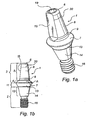
- Fig. 1a is a perspective view of a first embodiment of an abutment
- Figs 1b to 1e are lateral views of the same abutment as in Fig. 1a .
- abutment for connection of a dental component to an implant is depicted.
- the abutment comprises an implant contacting region 2 for connection to a dental implant and a component support region 3, extending coronally of said implant contacting region 2, for connection of a dental component thereto.
- the abutment would be used for connection of a dental prosthesis or crown to the implant.
- the abutment would be used for connecting other components to the implant, such as for example impression copings, healing caps or a temporary prosthesis.
- the abutment 1 may be made of a suitable material for dental components to be permanently installed in the mouth, such as for example titanium and certain ceramic materials, for example zirconium oxides.
- the component contacting region 3 is extending coronally from a maximum diameter A (see Fig. 1c ) to a coronal end 6.
- the maximum diameter A of the component contacting region is in this case coinciding with the maximum diameter of the abutment as a whole.
- Component engagement means 9 are provided at the component support region 3, coronally of the maximum diameter A.
- the component engagement means is structured and adapted for releasable engagement with a component by linear displacement of said component in relation to said abutment.
- the locations of the component engagement means 9 coronally of the maximum diameter A results in the attachment of the component being made where the abutment has a relatively narrow diameter, which is advantageous since it allows the components to be attached thereto to be constructed with a relatively small outer diameter.
- a small outer diameter makes it easier to install the component on the abutment without being hindered by adjacent teeth or having to push aside and damage the gingival tissue surrounding the abutment 1, when installed.
- the component engagement means 9 are provided at a distance from said maximum diameter A being less than 50 % of the distance between the maximum diameter A and the coronal end 6 of the abutment. Preferably, the distance should be less than 35 %, and, as in the embodiment of Figs 1a to 1e , the component engagement means 9 are provided at a distance being less than 25 % of the distance between the maximum diameter A and the coronal end 6 of the abutment.
- the implant contacting region 3 comprises in this first embodiment a shoulder portion 4 and a post portion 5, expending coronally from said shoulder portion.
- the outer surface 8 of the post portion 5 is forming an angle ⁇ less than 180° with the outer surface 7 of the shoulder portion. (See Fig. 1e ).
- the angle ⁇ formed between the outer surfaces 7, 8 of the shoulder portion 4 and the post portion 5 is preferably between 100° and 160°, more preferred 120 to 150°, most preferred 130 to 140°. In this embodiment, the angle ⁇ is 136°.
- the component engagement means 9 is provided at the transition between said shoulder portion 4 and post portion 5. This placement allows the major part of the post portion 5 to be modified without impairing the function of the component engagement means 9.
- the component engagement means 9 has the shape of a groove extending around part of the circumference of the post portion 5.
- the groove may be described as formed by a transition part 5' of the post portion 5 having an outer surface 8' that forms an angle ⁇ with the outer surface of the post portion 5.
- the angle ⁇ is preferably in the range 10 to 40°, more preferred 10 to 30° degrees, most preferred 12°.
- a component may be snap locked onto the groove formed by said transition part 5'.
- the angle ⁇ as defined above is suitable for forming such a snap lock having a preferred retaining force for securely retaining the component on the abutment 1 while still enabling the component to be released from said abutment 1.
- the component engagement means 9 is provided at a distance from the shoulder portion 4 being less than 50%, more preferred less than 30 % and, as in this embodiment, less than 20 % of the distance from the shoulder portion 4 to the coronal end 6 of the abutment.
- a component engagement means 9 may be considered as being provided at a distance from the shoulder portion 4 being less than 50 % the distance between the shoulder portion 4 and the coronal end 6 if the component engagement means 9 is still providing a component retaining function if a coronal portion of the abutment corresponding to 50 % of the distance between the shoulder portion 4 and the coronal end 6 is cut off. (A corresponding definition applies to the situation where the location of the component engagement means 9 are related to the maximum diameter A.)
- the post portion 5 is further provided with a rotational locking means 15 for rotational locking of a component attached to the abutment 1.
- the rotational locking means 15 is made out of a flat part of the outer surface 8 of the post portion 5.
- other shapes of the rotational locking means 15 may be considered. It is believed that a relatively smooth rotational lock function is preferred over more sharp and distinct locking means, since a smooth lock allows more play when installing a component on the abutment.
- the apical end 6 of the post portion is optionally provided with a polygonal blind bore 19, serving as attachment for a wrench for screwing the abutment onto an implant.
- an extension region 11 serving to increase the height with which the abutment 1 is extending over the implant when installed thereto.
- the extension region 11 When installed to an implant being flush with bone tissue, the extension region 11 would typically extend through gingival tissue.
- the implant contacting region 2 comprises a coronal contact portion 12 and a threaded shaft 16.
- the implant contacting region 2 is thereby adapted for connection to an implant having a conical coronal opening and being provided with internal threads for attachment of an abutment 1.
- the conical shape of the implant contacting region 2 and the implant opening, respectively, is particularly advantageous since it may be adapted to establish a conical seal when the implant and the abutment is screwed together.
- Fig. 1d the angles formed by the outer surfaces of different portions of the abutment 1 with a longitudinal axis L of the abutment are indicated.
- the outer surface 8 of the post portion 5 is tapering towards the coronal direction of the abutment. This is believed to be advantageous, since it allows more lateral play in an initial stage of attaching a component to the abutment 1, than would be the case if the outer surface 8 of the post portion 5 was parallel to the longitudinal axis L.
- the angle ⁇ formed by the outer surface 8 of the post portion 5 with the longitudinal axis L is preferably less than 20°, more preferred less than 15°. In this case, the angle ⁇ is 6°.
- angle ⁇ are particularly suitable for providing a post portion 5 that may cooperate with a component to provide a retaining function between the post portion 5 and the component.
- a transition part 5' of the post portion 5 having an outer surface 8' that forms an angle ⁇ with the outer surface of the post portion 5.
- the angle ⁇ may further be described in relation to the angle ⁇ between the longitudinal axis and the outer surface 8 of the post portion, as advantageously being 2 ⁇ ⁇ 10°.
- This particular choice of angle ⁇ enables a component attached to the abutment to be released from said abutment by linear displacement with essentially the same force that was needed for attaching the component to said component engagement means.
- the outer surface 8' of the transition part 5' of the post portion will namely be ⁇ ⁇ 10°, while the outer surface 8 of the post portion 5 in general forms an angle ⁇ with said longitudinal axis L.
- the force required for attaching the component onto the abutment will be dependent on the angle ⁇ formed by the outer surface 8 of the post portion 5 with said longitudinal axis L.
- the force required for removing the component from the abutment will be dependent on the angle formed by the outer surface 8' of said transition portion 5' with said longitudinal axis L.
- the angle ⁇ is 2 ⁇ ⁇ 10°
- this angle will be ⁇ ⁇ 10°, meaning that the force required for removing said component from said abutment is about the same as the force required for attaching said component to said abutment 1.
- the outer surface 7 of the shoulder portion 4 is likewise tapering inwardly in a coronal direction.
- the angle ⁇ formed by the outer surface 7 of the shoulder portion 4 with the longitudinal axis L is preferably in the range 40 to 60°. In this case, the angle ⁇ is 50° degrees.
- angle ⁇ formed between the outer surface 7 of the shoulder portion 4 and the outer surface 8 of the post portion 5 would be equal to (180°+ ⁇ - ⁇ ).
- the outer surface 13 of the extension region 11 may be parallel to a longitudinal axis of the abutment 1 or tapering outwardly in a coronal direction of the abutment 1.
- the angle ⁇ formed by the outer surface 13 of the extension region 11 with said longitudinal axis L may advantageously be varied so as to achieve a desired maximum diameter A.
- the angle ⁇ would be 90° to 180°.
- the angle ⁇ formed by the outer surface 14 of the coronal contact portion 12 of the implant contacting region 2 of the abutment 1, is preferably 165° to 170°, in this case 169°.
- the maximum diameter A of the abutment 1 is preferably in the range 3 to 7 mm, most preferred 3 to 6 mm.
- the maximum diameter B of the post portion 5 is in the range 2 to 5 mm.
- a shelf formed by the outer surface 7 of the shoulder portion 4 would in this embodiment have a width corresponding to half the difference between said maximum diameter A of the abutment and the maximum diameter B of the abutment. Preferably, this width may be in the range 0.2 to 1 mm, most preferred 0.5 mm.
- the axial extension of the shoulder portion 4 may be in the range 10-40 %, preferably 20 % as compared to an axial extension of the entire component support region 3.
- the axial extension of the extension region 11 may advantageously be selected so as to achieve a desired height of the abutment. Normally, the extension region 11 would have an axial extension of about 10 % to 50% of the axial extension of the component support region 3.
- the abutment 1 may be provided with one or several markings 20 indicating a level for shortening of the abutment.
- Fig. 2a is a perspective view of a second embodiment of an abutment.
- Fig. 2b is a sectional view of the abutment of Fig. 2a .
- Features corresponding to features of the above mentioned first embodiment of Figs 1a to 1e have been provided with the same reference numerals as used in Figs 1a to 1e . Only the parts of this second embodiment that differ from the first embodiment will be described below.
- the second embodiment differs from the first embodiment in that the implant contacting region 2 is not provided with a threaded shaft 16. Instead, it has a hexagonal locking structure 21 for rotational lock to an implant.
- the abutment 1 is further provided with a through bore 17 having an internal ledge 18. A screw may be inserted in the through bore 17, seating the screw head on the ledge 18, for connection of the abutment 1 to an implant. This type of abutment is particularly useful for single-tooth restoration situations.
- Fig. 3 is a side view of a third embodiment of an abutment.
- Features corresponding to features of the above mentioned first embodiment of Figs 1a to 1e have been provided with the same reference numerals as used in Figs 1a to 1e . Only the parts of the third embodiment that differ from the first embodiment will be described below.
- the third embodiment of the abutment differs from the first embodiment mainly in the height and shape of the post portion 5.
- the height of the post portion 5 is shortened as compared to the first embodiment, and constitutes approximately 75 to 80 % of the axial extension of the component support region 3. (This leaving about 20 to 25 % of the axial extension to the shoulder portion 4).
- the actual length of said post portion is about 2 mm.
- the angle ⁇ formed by the outer surface 8 of the post portion 5 with the longitudinal axis L is 11°.
- An advantage with using an abutment 1 with a short post portion 5 is that the abutment 1 will not need being modified very often. Instead, the prosthesis may be built on the post portion 5 in its original shape.
- Fig. 4 is a side view of a fourth embodiment of an abutment 1.
- Features corresponding to features of the above mentioned first embodiment of Figs 1a to 1e have been provided with the same reference numerals as used in Figs 1a to 1e . Only the parts that differ from the first embodiment will be described below.
- the fourth embodiment differs from the first embodiment in that the extension region 11 is made very short and its outer surface 13 is forming a rather large angle ⁇ with said longitudinal axis L.
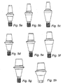
- Figs 5a to 5h depicts an embodiment of a series of abutments of the types described in Figs 1a to 4 .
- the reference numerals in the following description of Figs 5a to 5h may be referred to features described in Figs 1a to 4 .
- Figs 5a to 5h depicts a series of abutments wherein the angle ⁇ formed between the outer surface 8 of the post portion 5 and the outer surface 7 of the shoulder portion 8 is constant for all abutments in said series. Further, the longitudinal extension of a component support region 3 is constant between all abutments in said series.
- Figs 5a to 5c these three abutments further belong to a series in which the maximum diameter A is constant for all abutments in said series.
- the three abutments of Figs 5d to 5f have a common maximum diameter
- the two abutments of Figs 5g to 5h have a common maximum diameter.
- the abutments of Figs 5a to 5c have a maximum diameter of 4 mm
- the abutments of Figs 5d to f have a maximum diameter of 5 mm
- the abutments of Figs 5g and 5h have a maximum diameter of 6 mm.
- Figs 5a to 5h describes a series of abutments 1 for connection of a dental component to an implant, each abutment having a longitudinal axis L and comprising an implant contacting region 2, a component support region 3 and an extension region 11 there between 3, wherein
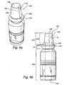
- Fig. 6a is a perspective view of an embodiment of an abutment replica 101
- Fig. 6b is a side view of the same abutment replica 101.
- the abutment replica 101 comprises a component support region 103, an extension region 111 and an apical region 102.
- the component support region 103 replicates the component support region of an abutment 1, in this case an abutment 1 of the type depicted in Figs 1a to 1e .
- the component support region 103 has a shoulder portion 104 with an outer surface 107 and a post portion 105 with an outer surface 108.
- the abutment replica 101 is provided with component engagement means 109 replicating the component engagement means 9 of the abutment 1.
- the abutment replica 101 is provided with a bore 130 extending from an apical end of the apical portion 102 to a position coronally of said component engagement means 109.
- the bore 130 is a blind bore, but one could also consider having a bore extending all the way through the replica 101.
- the bore 130 becomes useful in situations where the abutment replica 101 should be used for model making of a modified standard abutment, as is described in more detail in relation to Figs 11a to 11h below.
- a coronal part of the post portion 105 is cut off the abutment replica 101, leaving the remaining abutment replica 101 with a through bore 130 extending therethrough.
- the through bore 130 may be used for pouring moulding material from the apical end of the replica 101 for making a model of a modified abutment.
- the abutment replica 101 is useful in pick-up impression making, regardless of whether standard or modified abutments are used.
- a set comprising an abutment 1 having a coronal abutment end 6 and a corresponding replica 101 having a coronal replica end 106, said abutment 1 being provided with a marking for optional shortening of the abutment 1 at a first distance from the coronal abutment end 6, wherein said replica 101 is provided with a marking at a second distance from the coronal replica end 106 being equal to or slightly less than said first distance.
- Such a set provides an alternative to other modification of the abutment.
- the dental technician may shorten the abutment 1 at the marking 20.
- the replica 101 is provided with a corresponding marking 120 at approximately the same height as the marking of the abutment 1.
- the dental technician need not use specific impression techniques for capturing the modified shape of the abutment 1 when shortened, but can instead use standard techniques only to capture the location of the abutment 1.
- the replica 101 is shortened to the same extent as were the abutment 1, and will thus faithfully replicate the situation in the mouth.
- the marking of the replica 101 may advantageously be made at a distance from the replica end 106 being slightly less than the corresponding distance on the abutment 1. This is to provide a small margin for the dental technician when cutting of the components, without risking that the abutment replica 101 turns out to be shorter than the abutment 1.
- the replica 101 and abutment 1 may each be provided with several markings.
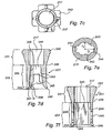
- Figs 7a and 7b are perspective views of an embodiment of an impression coping for pick up impression making of a dental abutment attached to a dental implant.
- Fig 7c is a bottom view of the same impression coping
- Fig. 7d is a sectional view seen from the plane d-d in Fig. 7a
- Fig. 7e is a sectional view seen from the plane e-e in Fig. 7a
- Fig. 7f is a sectional view from the plane f-f in Fig. 7a .
- the impression coping as described in Figs 7a to 7f comprises an abutment surrounding region 203 for seating on an abutment 1.
- the abutment surrounding region 203 has a coronal end 206 and an apical end 240, and is provided with an inner wall 207,208.
- the abutment surrounding region 203 comprises a shoulder contacting portion 204 having an inner wall 207 and a post surrounding portion 205 having an inner wall 208.
- the shoulder contacting portion 204 is intended to be seated on a shoulder portion of a corresponding abutment, whereas the post surrounding portion 205 will surround a post portion of said abutment.
- abutment engagement means 209 are provided for releasable engagement with an abutment by linear displacement of said impression coping in relation to said abutment.
- Said abutment engagement means 209 is provided closer to the apical end 240 of the abutment contacting portion 203 than to the coronal end 206.
- the distance between said apical end 240 and the abutment engagement means 209 is less than 50%, more preferred less than 35%, most preferred less than 25% the distance between the apical end 240 and the coronal end 206 of the abutment surrounding region 203.
- a distance between said shoulder contacting portion 204 and the abutment engagement means 209 is preferably less than 50% the distance between the shoulder contacting portion 204 and the coronal end 206 of the abutment surrounding region 203, more preferred less than 30%, most preferred less than 20%.
- the abutment engagement means 109 comprises a rib extending around part of the inner circumference of the inner wall 208 of the post surrounding portion 205.
- the rib is interrupted by the provision of flat surface functioning as a rotational lock 215 extending on the inner wall 208 of the post portion 205. It is further interrupted where space forming surfaces 244 are provided, said surfaces 244 being described further below.
- the rib functions as a snap lock means when cooperating with a corresponding groove of an engagement means 9 on an abutment 1, realisably locking the impression coping 201 in an axial direction on the abutment 1.
- the inner wall 208 of the post contacting region 205 comprises surface regions having different purposes.
- a first surface region is an abutment contact surface 243 for contact with the abutment 1 when seated.
- a second surface region is a space forming surface 244, that is spaced apart from the abutment 1 when seated, forming an open space between the abutment 1 and the space forming surface 244.
- the abutment contact surface 243 serves to stabilise the impression coping 201 when seated on an abutment 1, and to ensure that the impression coping 201 is correctly positioned.
- the space forming surface 244 serves to provide an open space between the abutment 1 and the inner wall 208 of the impression coping 201. This is particularly useful when taking an impression of a modified standard abutment, as is described in relation to Figs 11a to 11h below.
- a distance r1 from a longitudinal axis L of the impression coping 201 to an abutment contact surface 243 is shorter then a distance r2 from said longitudinal axis L to a space forming surface 244.
- abutments 1 are usually symmetrical or close to symmetrical around a longitudinal axis, why an asymmetrical inner surface of the impression coping 201 generally means that spaces between the impression coping 201 inner surface and the abutment 1 will be provided when the impression coping 201 is attached to the abutment 1.
- the space forming surface 244 is a surface deviating from an outer contour of a corresponding abutment, while the abutment contact surface 243 is a surface following said outer contour.
- said space forming surface 244 may be provided with a vent 245 for passage of air from said space formed between the space forming surface 244 and a corresponding abutment, when the impression coping 201 is seated on said abutment.
- a vent 245 for passage of air from said space formed between the space forming surface 244 and a corresponding abutment, when the impression coping 201 is seated on said abutment.
- the vent 245 is an opening in the wall of said impression coping.
- the vent may also be provided by for example a perforation.
- the space forming surfaces 244 are extending longitudinally along the inner wall 208 of the post surrounding portion. As such they may form ducts for air and sometimes impression material to flow through. Vents 245 may be provided at the apical end of such ducts, being the most advantageous location for ensuring that air is let out, provided the impression material is filled from a coronal end of the impression coping 201. Also, vents 245 may be dispersed over the space forming surfaces.
- space forming surface 244 and "abutment contact surface” 243 is related to when the impression coping 201 is seated on an unmodified abutment. However, when taking an impression of a modified abutment, all of the abutment contact surface 243 will probably not be in contact with the modified abutment. At least a portion of the abutment contact surface 243 will most likely not contact the customised abutment, due to the modified shape thereof.
- a composite space is formed between the abutment and the inner wall of the impression coping 201, said composite space being composed by a space between the abutment contact surface 243 and the modified abutment and a space between said space forming surface 244 and said modified abutment.
- Impression material may be introduced into the impression coping 201 and into the composite space formed between said impression coping 201 and the modified abutment.
- the space forming surface 244 thus provides an air duct for air evacuation from said composite space.
- the abutment may alternatively be modified such that all of the abutment contact surface is still in contact with the modified abutment, and the composite space is related only to the space forming surfaces.
- the abutment contact surfaces 243 is tapering inwardly in a coronal direction, preferably forming an angle less than 20°, more preferred less than 15° with a longitudinal axis. In this case, said angle is 6°. Further, the abutment contact surfaces form an angle with the shoulder contacting portion 204, said angle being larger than 180°, preferably 220 to 230°.
- the impression coping 201 is further provided with a prolongation region 241 being provided coronally of the abutment surrounding region 203.
- the prolongation region 241 serves to provide a larger area for the impression material to attach to the impression coping 201. Further, it facilitates handling of the impression coping 201.
- the prolongation region 241 is provided with laterally extending retention elements 242.
- the impression coping may preferably be made of a plastic material.
- a plastic material may be selected so as to provide sufficient elasticity to allow formation of a snap lock means, but not being easily deformable so that the stable transfer of location of an abutment during impression making is not impaired.
- FIGs 8a and 8b an abutment 1 is shown as attached to a dental implant 401 implanted in bone tissue 500.
- An impression coping 201 is connected to the abutment 1.
- FIG. 8a and Fig. 8b are cross-sectional views, Fig. 8b being taken through the plane b-b in Fig. 8a .
- the abutment 1 is of the type described in Figs 1a to 1e , and the impression coping 201 of the type described Figs 7a to 7f .
- the reference numerals used in the descriptions of the abutment 1 and the impression coping 201 will be used in the following, although they are not set out in Figs 8a and 8b for lack of space.
- the abutment 1 is connected to the dental implant 401 via the implant contacting region 2 of the abutment.
- the threaded shaft 16 is threaded into internal threads of a coronal bore of the implant.
- the coronal contact portion 12 of the implant contacting region 2 is in sealing contact with a conical portion of said coronal bore of the implant 401.
- the extension region 11 of the abutment is extending from implant coronal end through the gingival tissue 501.
- the outer diameter of the abutment is increasing from the implant contacting region 2 to a maximum diameter A at the coronal end of the extension region 11.
- the component support region 3 with the shoulder portion 4 and the post portion 5 is extending above the gingival tissue 501.
- the component engagement means 9 is provided at the transition between the shoulder portion 4 and the post portion 5, thus coronally of both the maximum diameter A of the abutment 1, and of the shoulder portion 4.
- the impression coping 201 is realisably locked to the component engagement means 9 of the abutment 1 by its own abutment engagement means 209. As seen in Figs 8a and 8b , the maximum diameter of the impression coping 201 is about as large as the maximum diameter A of the abutment 1. The impression coping 201 is thus easily connectable to the abutment 1 without risk of damaging the mucosal tissue surrounding the abutment. This would also be the case if the mucosal tissue were somewhat thicker, extending further coronally on the abutment.
- Fig. 8a it is seen that the space forming surfaces 244 of the impression coping 201 is spaced from the abutment 1.
- the spaces thus provided form ducts extending from the coronal end of the through passage 217 of the impression coping 201 along the side of the abutment and to the vents 245.
- Fig. 8b the abutment contact surfaces 243 is seen to contact the abutment 1, providing support and guidance for said impression coping 201.
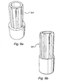
- Figs 9a to 9b are perspective views of another component that may be connected to an abutment as shown in Figs 1a to 1e .
- the component is an abutment carrier 301, having an apical abutment contact portion and a coronal extension portion having a ribbed outer surface to facilitate gripping of the component.
- the abutment carrier 301 may be attached to the abutment for facilitating handling and attachment of the abutment to an implanted fixture.
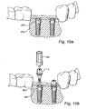
- Figs 10 a to 10 b describes pick-up impression making and model forming when using a standard abutment 1.
- Fig. 10a two dental implants 401 are shown as implanted flush with bone tissue 500 at an implantation site between adjacent teeth.
- FIG. 10b it is illustrated how an abutment 1 is screwed into each of the implants 401 using an abutment carrier 301.
- the abutment 1 is attached to the carrier 301 before being brought to the implantation site.
- the dental surgeon initially screws the abutment 1 into the implant 401 holding the carrier 301.
- the carrier 301 is removed, and the abutment 1 may optionally be further tightened to the implant 401 using a wrench.
- impression copings 201 are attached onto the abutments 1 using the component engagement means 9 of the abutment 1 and the abutment engagement means 209 of the impression coping 201.
- impression material may be introduced into the impression coping 201.
- a standard abutment 1 is used, this is not necessary.
- impression material 600 has been applied, embedding the impression copings 201 in the impression material 600.
- the impression material 600 is let to harden so as to mimic the shape of the teeth adjacent the impression site and attach to the impression copings 201.
- Fig. 10e the impression material 600 have been removed from the implantation site, bringing the impression copings 201 along embedded in the material 600.
- Fig. 10f it is depicted how standard abutment replicas 101 are introduced into the impression copings 201 attached in the impression material. Due to engagement means and rotational locking means on the abutment replicas 101 and impression copings 201, respectively, the abutment replicas 101 are placed in the impression copings 201 in a position corresponding to the initial position of the abutments 1 in the impression copings 201.
- mould material 700 have been applied to the impression material 600.
- Fig 10h the impression material 600 and the impression copings 201 have been removed.
- the moulding material 700 now form a model of the implantation site with the adjacent teeth, and with the abutment replicas 101 corresponding to the abutments 1 at the actual implantation site. Using this model, a proper prosthesis or crown may be manufactured and adjusted, for later installation on the proper abutments 1 at the installation site.
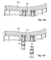
- Figs 11a to 11h describes pick-up impression making and model forming when using a modified abutment 1.
- Fig. 11a two dental implants 401 are shown as implanted flush with bone tissue 500 at an implantation site between adjacent teeth.
- abutments 1 are screwed into the implants 401 using abutment carriers 301.
- the abutment 1 is attached to the carrier 301 before being brought to the implantation site.
- the dental surgeon initially screws the abutment 1 into the implant 401 holding the carrier 301.
- the carrier 301 is removed, and the abutment 1 may optionally be further tightened to the implant 401 by using a wrench.
- the standard abutments 1 are modified for example as shown by removing a part of the coronal portion of the abutment 1. The remaining portion is a modified abutment 1'.
- impression copings 201 are attached onto the modified abutments 1' using the component engagement means of the modified abutments 1' and the abutment engagement means of the impression copings 201, respectively. Since the abutments 1' are modified, it is necessary to introduce impression material 600' into the impression copings 201.
- the impression material 600' may advantageously be introduced through the coronal end of the through passage of the coping. When introducing impression material 600' through the coronal end of the through passage, air may flow through the spaces formed by the space forming surfaces 244 of the impression coping 201 and out of the vents 245, whereby air bubbles or inadequate filling of the impression coping 201 is avoided. If properly introduced, the impression material 600' together with part of the abutment contact surfaces 243 of the impression coping 201 will form an open space corresponding to the shape of the modified abutment 1'.
- impression material 600 has been applied, embedding the impression copings 201.
- the impression material 600 is let to harden so as to mimic the shape of the teeth adjacent the impression site and attach to the impression copings 201.
- Fig. 11f it is depicted how a coronal portion is cut off a standard abutment replica 101, so as to reveal a bore passing through the remaining part of the replica 101'.
- the remaining part is referred to as a cut-off replica 101'.
- Cut-off replicas 101' are introduced into the impression copings 201 embedded in the impression material using component engagement means 109. Thereafter, mould material 700' is filled through the bore in the cut-off replica 101' into the open space formed by the impression material 600' inside the impression coping 201' and part of the abutment contact surfaces 243 of the impression coping 201.
- Fig 11h the impression material 600 and the impression copings 201 have been removed.
- the moulding material 700 now forms a model of the implantation site with the adjacent teeth.
- the moulding material 700' that was filled through the cut-off replicas 101' replicates the upper part of the original modified abutments 1'.
- shoulder parts of the cut-off replicas 101' correspond to the shoulder parts of the original abutments 1 at the implantation site.
- a proper prosthesis or crown may be manufactured and adjusted, for later installation on the proper abutments 1 at the installation site.
- the components described may possibly be consisting of two or more interconnected parts. However, the unitary embodiments described herein are preferred.
- engagement means and rotational locking means may also be varied, as may the outer shape of for example the impression coping, the connection to an implant of the abutment or the apical portion of the abutment replica.
Claims (38)
- Abutment (1) zum Verbinden einer Zahnkomponente mit einem Implantat, wobei das Abutment (1) Folgendes umfasst:einen Implantatkontaktbereich (2), einen Komponententragbereich (3) und ein koronales Ende (6), wobei:der Komponententragbereich (3) einen maximalen Durchmesser (A) aufweist und sich koronal von dem maximalen Durchmesser bis zu dem koronalen Ende (6) erstreckt und mit einer Komponenteneingriffsvorrichtung (9) versehen ist, die zum lösbaren Eingriff mit der Zahnkomponente durch lineare Verlagerung der Zahnkomponente mit Bezug auf das Abutment (1) angeordnet ist,sich die Komponenteneingriffsvorrichtung (9) in einer Position befindet, die näher an dem maximalen Durchmesser (A) als an dem koronalen Ende (6) liegt,der Komponententragbereich (3) einen Bundabschnitt (4), der eine Außenfläche (7) aufweist, und einen Pfostenabschnitt (5), der sich koronal von dem Bundabschnitt (4) bis zu dem koronalen Ende (6) erstreckt und eine Außenfläche (8) aufweist, die einen Winkel (α) von weniger als 180° zu der Außenfläche (7) des Bundabschnitts (4) bildet, umfasst,der Implantatkontaktbereich (2) einen koronalen Kontaktabschnitt (12) umfasst, der eine Außenfläche (14) aufweist, die sich in koronaler Richtung des Abutments (1) verjüngt,sich die Außenfläche (7) des Bundabschnitts (4) in einer koronalen Richtung des Bundabschnitts (4) von einem maximalen Schulterdurchmesser (A) aus nach innen verjüngt, unddie Komponenteneingriffsvorrichtung (9) mindestens einen Vorsprung oder eine Vertiefung in einer Außenfläche (7, 8) des Komponententragbereichs (3) umfasst.
- Abutment nach Anspruch 1, wobei die Komponenteneingriffsvorrichtung (9) in einem Abstand von dem maximalen Durchmesser (A) bereitgestellt wird, der kleiner als 50 % des Abstands zwischen dem maximalen Durchmesser (A) und dem koronalen Ende (6), bevorzugt kleiner als 35 %, höchst bevorzugt kleiner als 25 % ist.
- Abutment nach Anspruch 1 oder 2, wobei die Komponenteneingriffsvorrichtung (9) in einem Abstand von dem Bundabschnitt (4) bereitgestellt wird, der kleiner als 50 % des Abstands zwischen dem Bundabschnitt (4) und dem koronalen Ende (6), bevorzugt kleiner als 30 %, höchst bevorzugt kleiner als 20 % ist.
- Abutment nach einem der vorhergehenden Ansprüche, wobei der Winkel (a) in dem Bereich von 100 bis 160°, weiter bevorzugt von 120 bis 150°, höchst bevorzugt von 130 bis 140° liegt.
- Abutment nach einem der vorhergehenden Ansprüche, wobei die Komponenteneingriffsvorrichtung (9) mit einem Übergang zwischen dem Pfostenabschnitt (5) und dem Bundabschnitt (4) bereitgestellt wird.
- Abutment (1) nach einem der vorhergehenden Ansprüche, wobei die Komponenteneingriffsvorrichtung (9) durch ein Übergangsteil (5') des Pfostenabschnitts (5) gebildet wird, der eine Außenfläche (8') aufweist, die einen Winkel (δ) mit der Außenfläche (8) des Pfostenabschnitts bildet.
- Abutment (1) nach Anspruch 6, wobei der Winkel (δ) in dem Bereich von 10 bis 40°, weiter bevorzugt von 10 bis 30°, höchst bevorzugt bei 12° liegt.
- Abutment (1) nach einem der vorhergehenden Ansprüche, wobei sich die Außenfläche (8) des Pfostenabschnitts (5) in einer koronalen Richtung des Pfostenabschnitts (5) von einem maximalen Pfostendurchmesser (B) aus nach innen verjüngt.
- Abutment (1) nach Anspruch 8, wobei der Pfostenabschnitt (5) eine Längsachse (L) aufweist, und die Außenfläche (8) des Pfostenabschnitts (5) einen Winkel (Φ) bildet, der kleiner als 20°, bevorzugt kleiner als 15°, höchst bevorzugt gleich 6° mit Bezug auf die Längsachse (L) ist.
- Abutment (1) nach einem der Ansprüche 6, 7 und 9, wobei der Winkel (δ), der durch die Außenfläche (8') des Übergangsteils (5') des Pfostenabschnitts (5) mit der Außenfläche (8) des Pfostenabschnitts (5) gebildet wird, gleich 2Φ +10° ist, wobei Φ der Winkel ist, der von der Außenfläche (8) des Pfostenabschnitts (5) mit der Längsachse (L) gebildet wird.
- Abutment (1) nach einem der vorhergehenden Ansprüche, wobei das Abutment (1) eine Längsachse (L) aufweist, und die Außenfläche (7) des Bundabschnitts (4) einen Winkel (X) in dem Bereich von 40 bis 60°, bevorzugt gleich 50° mit Bezug auf die Längsachse (L) bildet.
- Abutment (1) nach einem der vorhergehenden Ansprüche, wobei der Pfostenabschnitt (5) einen maximalen Durchmesser (B) in dem Bereich von 2 bis 5 mm aufweist.
- Abutment (1) nach einem der vorhergehenden Ansprüche, wobei der Pfostenabschnitt (5) einen maximalen Durchmesser (B) aufweist, der kleiner als der maximale Schulterdurchmesser (A) ist, wobei der Unterschied zwischen den maximalen Durchmessern (A und B) in dem Bereich von 0,2 bis 1 mm, bevorzugt bei 0,5 m liegt.
- Abutment (1) nach einem der vorhergehenden Ansprüche, wobei eine Axialerstreckung des Bundabschnitts (4) in dem Bereich von 10 % bis 40 %, bevorzugt von 20 % bis 30 % einer Axialerstreckung des Komponententragbereichs (3) liegt.
- Abutment (1) nach einem der vorhergehenden Ansprüche, wobei der maximale Durchmesser (A) des Komponententragbereichs (3) mit dem maximalen Durchmesser des Abutments (1) zusammenfällt.
- Abutment (1) nach einem der vorhergehenden Ansprüche, wobei die Komponenteneingriffsvorrichtung (9) Teil einer Einrastvorrichtung ist.
- Abutment (1) nach Anspruch 16, wobei die Komponenteneingriffsvorrichtung (9) eine Rille oder Rippe umfasst, die sich mindestens teilweise um einen Umfang der Außenfläche (7, 8) des Komponententragbereichs (3) herum erstreckt.
- Abutment (1) nach einem der vorhergehenden Ansprüche, wobei das Abutment (1) ferner einen Erstreckungsbereich (11) aufweist, der zwischen dem Implantatkontaktbereich (2) und dem Komponententragbereich (3) bereitgestellt wird.
- Abutment (1) nach Anspruch 18, wobei der Erstreckungsbereich (11) eine Außenfläche (13) aufweist, die zu einer Längsachse (L) des Erstreckungsbereichs (11) parallel ist oder sich in der koronalen Richtung nach außen verjüngt.
- Abutment (1) nach Anspruch 18 oder 19, wobei der Übergang zwischen dem Erstreckungsbereich (11) und dem Komponententragbereich (3) den maximalen Durchmesser (A) des Komponententragbereichs (3) definiert.
- Abutment (1) nach einem der Ansprüche 18 bis 20, wobei das Abutment (1) eine Längsachse (L) aufweist, und die Außenfläche (13) des Erstreckungsbereichs (11) einen Winkel (ϕ) in dem Bereich von 90° bis 180° zur Längsachse bildet.
- Abutment (1) nach einem der Ansprüche 18 bis 23, wobei eine Axialerstreckung des Erstreckungsbereichs (11) in dem Bereich von 10 % bis 50 % im Vergleich zu einer Axialerstreckung des Komponententragbereichs (3) liegt.
- Abutment (1) nach Anspruch 1, wobei das Abutment (1) eine Längsachse (L) aufweist und die Außenfläche (14) des koronalen Kontaktabschnitts (12) einen Winkel (ω) mit der Längsachse (L) bildet, wobei der Winkel (ω) in dem Bereich von 165 bis 170°, bevorzugt bei 169° liegt.
- Abutment (1) nach einem der vorhergehenden Ansprüche, wobei der maximale Durchmesser (A) des Komponententragbereichs (3) in dem Bereich von 3 bis 7 mm, bevorzugt von 3 bis 6 mm liegt.
- Abutment (1) nach einem der vorhergehenden Ansprüche, wobei der Komponententragbereich (3) mit mindestens einer Drehsperre (15) zum drehmäßigen Sperren der Zahnkomponente auf dem Abutment (1) versehen ist.
- Abutment (1) nach Anspruch 25, wobei die Drehsperre (15) in der Außenfläche (7, 8) des Komponententragbereichs (3) gebildet ist.
- Abutment (1) nach Anspruch 26, wobei die Drehsperre (15) durch einen flachen Abschnitt der Außenfläche (7, 8) des Komponententragbereichs (3) gebildet ist.
- Abutment (1) nach einem der vorhergehenden Ansprüche, wobei der Implantatkontaktbereich (2) einen apikalen Gewindeschaft (16) zur Verbindung mit dem Innengewinde eines Implantats umfasst.
- Abutment (1) nach einem der vorhergehenden Ansprüche, wobei das Abutment (1) mit einer Durchbohrung (17) versehen ist, die eine Leiste (18) zum Aufsetzen einer Schraube zum Verbinden des Abutments (1) mit einem Implantat definiert.
- Abutment (1) nach einem der vorhergehenden Ansprüche, wobei sich ein vieleckiges Sackloch (19) von dem koronalen Ende (6) in das Abutment (1) erstreckt, wobei das vieleckige Sackloch (19) nützlich ist, um einen Schraubenschlüssel anzusetzen, wenn das Abutment (1) an einem Implantat angebracht wird.
- Abutment (1) nach einem der vorhergehenden Ansprüche, wobei das Abutment mit mindestens einer Markierung (20) versehen ist, die zum wahlweisen Kürzen des Abutments (1) koronal zum Komponenteneingriffsmittel (9) positioniert ist.
- Satz, umfassend ein Abutment (1) nach einem der Ansprüche 1 bis 31 und ein Abutment-Analog (101), das einen Komponententragbereich (103) umfasst, der die äußere Form des Komponententragbereichs (3) des Abutments (1) aufweist, der analoge Komponenteneingriffsmittel (109) umfasst.
- Satz nach Anspruch 32, wobei sich eine Bohrung (130) von einem apikalen Ende des Abutment-Analogs (101) in das Abutment-Analog (101) mindestens bis zu einer Position koronal zu den Komponenteneingriffsmitteln (109) erstreckt.
- Satz nach Anspruch 32 oder 33, wobei die Bohrung (130) ein Sackloch ist, das an einer Position koronal zu den Komponenteneingriffsmitteln (109) endet.
- Satz nach einem der Ansprüche 32 bis 34, wobei das Abutment-Analog mit einer Markierung (120) versehen ist, die zum optionalen Kürzen des Abutment-Analogs (101) koronal zu den Komponenteneingriffsmitteln (109) positioniert ist.
- Satz, umfassend ein Abutment (1) zum Verbinden einer Zahnkomponente mit einem Implantat und eine Abformkappe (201) zur Überabformung des Abutments (1),
wobei das Abutment (1) ein Abutment nach einem der Ansprüche 1 bis 31 ist, und
wobei die Abformkappe (201) einen Abutment-Umgebungsbereich (203) umfasst, um das Abutment (1) zu umgeben, und eine Innenwand (208) aufweist, die mit einer Abutment-Eingriffsvorrichtung (209) versehen ist, die der Komponenteneingriffsvorrichtung (9) des Abutments (1) zum lösbaren Eingriff der Abformkappe (201) mit dem Abutment (1) durch lineare Verlagerung der Zahnkomponente mit Bezug auf das Abutment (1) entspricht. - Satz nach Anspruch 36, wobei ein maximaler Außendurchmesser eines Abutment-Kontaktabschnitts (203) der Abformkappe (201) kleiner oder gleich dem maximalen Durchmesser (A) des Abutments (1) ist.
- Satz nach Anspruch 36 oder 37, wobei die Abdruckkappe (201) einen Durchgang aufweist, der sich von einem koronalen Ende bis zu einem apikalen Ende der Abformkappe (201) erstreckt, und einen Abutment-Umgebungsbereich (203) zum Aufsitzen auf dem Abutment (1) umfasst, wobei die Innenwände (207, 208) des Abutment-Umgebungsbereichs (203) mindestens eine Pfostenkontaktfläche (243) zum Kontakt mit dem Abutment (1) und mindestens eine Platz schaffende Oberfläche (244), die von dem Abutment (1) zu beabstanden ist, um Platz für eine optionale Einführung von Abformmasse zwischen der Platz schaffenden Oberfläche (244) und dem Abutment (1) bereitzustellen, umfasst.
Applications Claiming Priority (3)
| Application Number | Priority Date | Filing Date | Title |
|---|---|---|---|
| US09/985,129 US6824386B2 (en) | 2001-11-01 | 2001-11-01 | Components for improved impression making |
| US985129 | 2001-11-01 | ||
| PCT/SE2002/001995 WO2003037208A1 (en) | 2001-11-01 | 2002-11-01 | Components for improved impression making |
Publications (2)
| Publication Number | Publication Date |
|---|---|
| EP1448113A1 EP1448113A1 (de) | 2004-08-25 |
| EP1448113B1 true EP1448113B1 (de) | 2015-12-23 |
Family
ID=25531223
Family Applications (1)
| Application Number | Title | Priority Date | Filing Date |
|---|---|---|---|
| EP02783906.7A Expired - Lifetime EP1448113B1 (de) | 2001-11-01 | 2002-11-01 | Komponenten für verbesserte abdrücke |
Country Status (12)
| Country | Link |
|---|---|
| US (2) | US6824386B2 (de) |
| EP (1) | EP1448113B1 (de) |
| JP (1) | JP4662710B2 (de) |
| KR (1) | KR100928655B1 (de) |
| CN (1) | CN100415184C (de) |
| AU (1) | AU2002347711B2 (de) |
| BR (1) | BR0213715A (de) |
| CA (1) | CA2466078C (de) |
| ES (1) | ES2562021T3 (de) |
| RU (1) | RU2299705C2 (de) |
| WO (1) | WO2003037208A1 (de) |
| ZA (1) | ZA200402596B (de) |
Cited By (1)
| Publication number | Priority date | Publication date | Assignee | Title |
|---|---|---|---|---|
| US20220192797A1 (en) * | 2020-12-17 | 2022-06-23 | Massimo Afflitto | Zygomatic implant |
Families Citing this family (85)
| Publication number | Priority date | Publication date | Assignee | Title |
|---|---|---|---|---|
| DE10159683A1 (de) * | 2001-11-30 | 2003-06-18 | Michael Gahlert | Dantalimplantat |
| US7066736B2 (en) * | 2002-09-12 | 2006-06-27 | Zimmer Dental, Inc. | Dental impression coping with retention |
| US7942669B2 (en) | 2002-12-02 | 2011-05-17 | Centrix, Inc. | Gingival tissue retraction device and method |
| US7241143B2 (en) * | 2002-12-02 | 2007-07-10 | Centrix, Inc. | Preloaded dental dam and method for gingival tissue retraction |
| US20040127909A1 (en) * | 2002-12-16 | 2004-07-01 | Morgan Vincent J. | Threaded dental or medical implants |
| ES2274172T3 (es) * | 2003-02-05 | 2007-05-16 | Straumann Holding Ag | Pieza de prolongacion para un implante dental, ayuda de transferencia y procedimiento para establecer una base para un elemento de retencion. |
| EP1506745A1 (de) * | 2003-08-15 | 2005-02-16 | Jeanette Mörmann | Rohling und Verfahren zur Herstellung einer Zahnrestauration |
| ITFI20040013A1 (it) * | 2004-01-19 | 2004-04-19 | Leone Spa | Impianto dentale |
| US20050233281A1 (en) * | 2004-04-19 | 2005-10-20 | Gittleman Neal B | Uniquely positioned, winged, low profile impression cap for use with triple tray |
| US20060003290A1 (en) * | 2004-07-01 | 2006-01-05 | Niznick Gerald A | Endosseous one-piece screw-type dental implants |
| US7785107B2 (en) * | 2005-02-01 | 2010-08-31 | Niznick Gerald A | Multi-functional fixture mount |
| US7699613B2 (en) * | 2005-02-11 | 2010-04-20 | Niznick Gerald A | One-piece, screw-receiving, externally-threaded endosseous dental implants and related transfer components, comfort caps and abutments |
| US20060199150A1 (en) * | 2005-03-07 | 2006-09-07 | Niznick Gerald A | Externally-threaded, one-piece endosseous dental implant with angled abutment |
| ES2415737T3 (es) | 2005-06-03 | 2013-07-26 | Straumann Holding Ag | Acoplamiento para un sistema de implante dental de múltiples partes |
| US8506296B2 (en) | 2005-06-17 | 2013-08-13 | Zimmer Dental, Inc. | Dental restorative system and components |
| US8007279B2 (en) * | 2005-06-17 | 2011-08-30 | Zimmer Dental, Inc. | Dental restorative system and components |
| US8430668B2 (en) * | 2005-06-17 | 2013-04-30 | Zimmer Dental, Inc. | Dental restorative system and components |
| PL1757245T3 (pl) * | 2005-08-22 | 2011-01-31 | Riemser Pharma Gmbh | Implant zęba |
| EP1757246A1 (de) | 2005-08-22 | 2007-02-28 | Novident SA | Aufbau für ein Zahnimplantat |
| US20070099152A1 (en) * | 2005-10-31 | 2007-05-03 | Albert Busch | Dental implant system |
| US7780446B2 (en) * | 2006-02-24 | 2010-08-24 | Zimmer Dental, Inc. | Ceramic/metallic dental abutment |
| EP2289460B1 (de) * | 2006-02-28 | 2013-04-03 | Straumann Holding AG | Aufbauteil |
| US8118595B2 (en) * | 2006-04-05 | 2012-02-21 | Centrix, Inc. | Conforming gingiva retraction compression cap and method of retracting tissue around a tooth |
| US7806692B2 (en) * | 2006-12-22 | 2010-10-05 | Implant Ingenuity Inc. | Implant abutment clips |
| US8753613B2 (en) | 2007-03-30 | 2014-06-17 | Centrix, Inc. | Dental retraction material having enhanced fluid absorption |
| US7806693B2 (en) * | 2007-04-23 | 2010-10-05 | Nobel Biocare Services Ag | Dental implant |
| JP4321636B2 (ja) | 2007-07-27 | 2009-08-26 | セイコーエプソン株式会社 | 歯科用インプラントの製造方法 |
| JP4321635B2 (ja) * | 2007-07-27 | 2009-08-26 | セイコーエプソン株式会社 | 歯科用インプラントの製造方法 |
| JP4321637B2 (ja) | 2007-07-27 | 2009-08-26 | セイコーエプソン株式会社 | 歯科用インプラントの製造方法 |
| JP4321638B2 (ja) | 2007-07-27 | 2009-08-26 | セイコーエプソン株式会社 | 歯科用インプラントの製造方法 |
| EP2231057A2 (de) * | 2007-10-26 | 2010-09-29 | Council of Scientific & Industrial Research | Zahnimplantat |
| US20100086900A1 (en) * | 2008-05-06 | 2010-04-08 | Keystone Dental, Inc. | Coping-analogue kit |
| US20110143317A1 (en) * | 2008-07-03 | 2011-06-16 | Geninho Thome | Straight Conic Mini Pillar Used in Outer Hexagon Implants |
| US8545222B2 (en) * | 2008-10-21 | 2013-10-01 | Chan Qian Wang | Method of dental implant restoration |
| US20100112527A1 (en) * | 2008-11-02 | 2010-05-06 | Timothy Dow Chapel | Method for fabricating an implanted dental restoration |
| US8454363B2 (en) * | 2008-11-06 | 2013-06-04 | William B. Worthington | Dental implant system |
| US20100159417A1 (en) * | 2008-12-18 | 2010-06-24 | Dale Whipple | Dental impression cap with engagement feature |
| EP2213259A1 (de) * | 2009-01-31 | 2010-08-04 | Straumann Holding AG | Abformpfosten für Dentalimplantat |
| SG173030A1 (en) * | 2009-02-04 | 2011-08-29 | Mid Corp | A system, method and apparatus for implementing dental implants |
| WO2010110857A2 (en) * | 2009-03-22 | 2010-09-30 | Wang Chan Q | A dental restoration system and method thereof |
| US8867800B2 (en) | 2009-05-27 | 2014-10-21 | James R. Glidewell Dental Ceramics, Inc. | Method of designing and fabricating patient-specific restorations from intra-oral scanning of a digital impression |
| US9149347B2 (en) * | 2009-07-27 | 2015-10-06 | Straumann Holding Ag | Abutment for a dental implant |
| EP2501324A4 (de) * | 2009-11-17 | 2013-04-24 | Uab Research Foundation | Zahnärztliches implantatsystem mit hohem drehmoment |
| KR101109625B1 (ko) * | 2010-02-23 | 2012-01-31 | 주식회사 티스트롱 | 임플란트용 어버트먼트 |
| DE202010017227U1 (de) * | 2010-04-29 | 2011-04-21 | Nt-Trading Gmbh & Co. Kg | Abutment für Zahnimplantat |
| US9763758B2 (en) | 2011-01-13 | 2017-09-19 | Align Technology, Inc. | Virtual and physical dental models of dental surfaces and analog socket structure of a dental implant and related procedures |
| USD668764S1 (en) | 2011-01-24 | 2012-10-09 | Straumann Holding Ag | Portion of a dental implant |
| EA028861B1 (ru) | 2011-02-02 | 2018-01-31 | Мид Корп | Зубной имплантат |
| ES2550221T3 (es) * | 2011-03-18 | 2015-11-05 | Elos Medtech Pinol A/S | Tope dental para escaneado bucal |
| AT511387B1 (de) * | 2011-04-20 | 2013-02-15 | Redtenbacher Praez Steile Ges M B H | Zahnprothese |
| US20120288826A1 (en) * | 2011-05-11 | 2012-11-15 | Fitton Iii Russell P | Dental Implants and Methods for Their Insertion into Patients |
| EP3777760A1 (de) | 2011-05-16 | 2021-02-17 | Biomet 3I, LLC | Temporärer stützpfeiler mit einer kombination aus abtastungsmerkmalen und provisorischen funktionen |
| US20130236855A1 (en) * | 2012-03-08 | 2013-09-12 | James R. Glidewell Dental Ceramics, Inc. | Premanufactured ceramic dental implant abutments for mating ceramic prosthetic build-up construction |
| KR101265969B1 (ko) | 2012-10-31 | 2013-05-22 | 라파바이오 주식회사 | 최적의 어뎁테이션을 얻을 수 있는 정밀가공 맞춤형 어버트먼트 제조방법 |
| US8905757B2 (en) | 2012-12-03 | 2014-12-09 | E. Kats Enterprises Ltd. | Method and apparatus for measuring a location and orientation of a plurality of implants |
| ES1078459Y (es) * | 2012-12-26 | 2013-04-22 | Montalban Joaquin Rovello | Pilar metalico para implantes dentales |
| TWI583359B (zh) * | 2013-02-22 | 2017-05-21 | 巴科納 包瑞斯 Ds | 預防骨質流失之骨內牙植體及基牙 |
| WO2014150907A1 (en) * | 2013-03-15 | 2014-09-25 | Haralampopoulos Harry A | Conversion abutment for dental implants |
| EP3003205B1 (de) * | 2013-06-06 | 2021-11-17 | Abracadabra Implants Ltd | Zahnimplantatvorrichtung |
| BR102013027205B1 (pt) * | 2013-10-22 | 2020-10-27 | Jjgc Indústria E Comércio De Materiais Dentários S.A. | sistema de componente protético multifuncional |
| IL230833A0 (en) * | 2014-02-05 | 2014-09-30 | Ophir Fromovich | bone graft |
| EP2949287A1 (de) * | 2014-05-27 | 2015-12-02 | Ivoclar Vivadent AG | Zahnersatz-Erzeugungsvorrichtung sowie Zahnersatz |
| US9572638B1 (en) | 2014-06-02 | 2017-02-21 | Lloyd T. Anderson | Impression coping spacer and method of dental casting |
| US9956060B2 (en) * | 2014-07-10 | 2018-05-01 | Csd Connection Systems For Dentistry Inc. | Dental prostheses cemented onto implants and/or abutments having a reverse margin |
| CN104546164B (zh) * | 2014-12-11 | 2017-09-29 | 大连三生科技发展有限公司 | 橡胶塞角度印模转移装置 |
| CN104546170B (zh) * | 2014-12-11 | 2016-08-17 | 大连三生科技发展有限公司 | 吸磁角度印模转移装置 |
| WO2017011898A1 (en) | 2015-07-20 | 2017-01-26 | Csd Connection Systems For Dentistry Inc. | Methods and devices for countering gingival effects in dental restoration |
| IL244188B (en) * | 2016-02-18 | 2020-08-31 | Kasem Yahya | Angular transfer for dental implants |
| US10368965B2 (en) * | 2016-07-22 | 2019-08-06 | Board Of Regents, The University Of Texas System | Systems and methods for dental abutments with cement-retained crowns |
| CN106691610A (zh) * | 2016-12-29 | 2017-05-24 | 北京爱康宜诚医疗器材有限公司 | 基台、转移杆及拆卸装置 |
| ES1182233Y (es) * | 2017-03-29 | 2018-05-25 | Xam Mar Mangrane Esteban | Aditamento de altura regulable para protesis dental |
| US20180333230A1 (en) * | 2017-05-18 | 2018-11-22 | P.O.M. Solutions, LLC | Dental component gripping device |
| ES2737500B2 (es) * | 2018-07-06 | 2021-07-30 | Implant Protesis Dental 2004 S L | Conjunto para formar una pieza de interfase para implantes dentales con una altura variable |
| CN108926400A (zh) * | 2018-08-03 | 2018-12-04 | 北京大清西格科技有限公司 | Dis用愈合基台、多功能合一的上部取模及修复方法 |
| ES1220239Y (es) * | 2018-10-01 | 2019-02-07 | Terrats Medical S L | Pieza de capuchón para escaneado dental |
| US11311354B2 (en) | 2018-10-09 | 2022-04-26 | Smart Denture Conversions, Llc | Screw-attached pick-up dental coping system and methods |
| KR102062575B1 (ko) * | 2019-05-02 | 2020-01-06 | 이젠임플란트 주식회사 | 지대주 및 이를 포함하는 임플란트 |
| KR102470652B1 (ko) * | 2020-02-21 | 2022-11-25 | (주)포인트닉스 | 향상된 체결구조를 갖는 임플란트용 임프레션 코핑 |
| EP3944836A1 (de) | 2020-07-27 | 2022-02-02 | Ruetschi Technology SA | Transferteil oder einführwerkzeug für ein zahnimplantat mit schnellfreigabemechanismus |
| KR102357622B1 (ko) * | 2021-05-21 | 2022-02-08 | 장현성 | 치과용 솔리드 어버트먼트 |
| TWI808494B (zh) * | 2021-09-22 | 2023-07-11 | 王建和 | 鎖固件 |
| KR102404199B1 (ko) * | 2021-10-28 | 2022-05-30 | 김진호 | 임플란트용 어버트먼트 |
| US20230141391A1 (en) * | 2021-11-05 | 2023-05-11 | Jonathan Abenaim | Scan body with healing abutment |
| US11957538B2 (en) | 2021-12-23 | 2024-04-16 | Smart Denture Conversions, Llc | Screw-attached pick-up dental coping system, methods and accessories |
| KR102580491B1 (ko) * | 2023-04-03 | 2023-09-21 | 권기수 | 하이브리드 임프레션 코핑 |
Citations (3)
| Publication number | Priority date | Publication date | Assignee | Title |
|---|---|---|---|---|
| WO1996029019A1 (de) * | 1995-03-20 | 1996-09-26 | Institut Straumann Ag | Verbindungsanordnung für implantat gestützten zahnersatz |
| WO1998052490A1 (de) * | 1997-05-24 | 1998-11-26 | Friadent Gmbh | Vorrichtung zur bildung eines zahnersatzes |
| WO1998052487A1 (de) * | 1997-05-24 | 1998-11-26 | Friadent Gmbh | Support zum halten und/oder bilden eines zahnersatzes |
Family Cites Families (52)
| Publication number | Priority date | Publication date | Assignee | Title |
|---|---|---|---|---|
| DE1232314B (de) | 1963-03-27 | 1967-01-12 | Frohnecke K G | Verfahren zum Einformen von Zaehnen und Vorrichtung zur Ausuebung des Verfahrens |
| US4177562A (en) | 1977-05-02 | 1979-12-11 | Miller Alvin L | Dental implant and method of inserting the same |
| US4253833A (en) | 1979-10-30 | 1981-03-03 | Edelman Alfred E | Submerged functional implant and method |
| DE3110693A1 (de) | 1981-03-19 | 1982-09-30 | Joannis Bademis | Kieferimplantat aus einem implantatkoerper und einem daran anschraubbaren, als kuenstlicher zahnstumpf fuer die befestigung eines zahnersatzteiles dienenden epimobilen aufsatz |
| US4575340A (en) | 1985-02-04 | 1986-03-11 | Lustig Leopold P | Precision dental restorative system |
| DE3531389A1 (de) * | 1985-09-03 | 1987-03-05 | Kirsch Axel | Enossales implantat |
| IL83261A0 (en) * | 1986-08-13 | 1987-12-31 | Ross Systems Corp | Process and apparatus for forming a dental prosthesis and installing same in a patient's mouth |
| US4738623A (en) | 1986-08-15 | 1988-04-19 | Quintron, Inc. | Dental implant and method |
| US4758161A (en) * | 1987-01-28 | 1988-07-19 | Core-Vent Corporation | Coping insert for use with a dental implant |
| SE456216B (sv) | 1987-04-22 | 1988-09-19 | Astra Meditec Ab | Verktyg for en protesdel |
| US4955811A (en) | 1988-06-23 | 1990-09-11 | Implant Innovations, Inc. | Non-rotational single-tooth prosthodontic restoration |
| JPH02136615U (de) * | 1989-04-19 | 1990-11-14 | ||
| SE464959B (sv) | 1990-01-18 | 1991-07-08 | Nobelpharma Ab | Avtryckstopp utfoerd i elastiskt material |
| US5334024A (en) | 1990-03-21 | 1994-08-02 | Core-Vent Corporation | Transfer abutment |
| US5135395A (en) * | 1990-07-05 | 1992-08-04 | Marlin Gerald M | Implant collar and post system |
| AT393952B (de) * | 1990-08-01 | 1992-01-10 | Sichler Heimo | Thermisch verstell- und fixierbarer implantatpfosten |
| US5662476A (en) | 1992-06-29 | 1997-09-02 | Nobel Biocare Ab | Prosthetic implant restoration method |
| US5297963A (en) | 1993-05-17 | 1994-03-29 | Fereidoun Dafatry | Anatomical restoration dental implant system with interlockable elliptical healing cap assembly and matching abutment member |
| US5376004A (en) | 1993-11-18 | 1994-12-27 | Mena; Raul | Dental implant device |
| DE4415670A1 (de) | 1994-05-04 | 1995-11-09 | Degussa | Abformkappe für Dentalimplantate |
| US5938443A (en) | 1994-11-08 | 1999-08-17 | Implant Innovations, Inc. | Impression coping for use in an open tray and closed tray impression methodology |
| US5899695A (en) | 1994-11-08 | 1999-05-04 | Lazzara; Richard J. | Anatomic interchangeable healing abutment and impression coping |
| US5685715A (en) | 1995-03-10 | 1997-11-11 | Beaty; Keith D. | Self-indexing transfer impression coping |
| ES2328089T3 (es) * | 1994-12-23 | 2009-11-06 | Raul R. Mena | Dispositivo de implante dental. |
| US5733124A (en) * | 1995-02-21 | 1998-03-31 | Kwan; Norman Ho-Kwong | Dental implant system |
| US5564924A (en) * | 1995-02-21 | 1996-10-15 | Kwan; Norman H. | Hexagonal abutment implant system |
| DE59600579D1 (de) | 1995-03-20 | 1998-10-22 | Straumann Inst Ag | Verbindungsanordnung eines dentalimplantats mit einem konus-sekundärteil |
| US5816809A (en) | 1995-09-20 | 1998-10-06 | Genetic Implant Systems, Inc. | Dental prosthesis support device and method of using same |
| US5904483A (en) | 1995-11-17 | 1999-05-18 | Wade; Curtis K. | Dental implant systems and methods |
| US6142782A (en) | 1996-01-05 | 2000-11-07 | Lazarof; Sargon | Implant assembly and process for preparing a prosthetic device |
| US5681167A (en) | 1996-01-05 | 1997-10-28 | Lazarof; Sargon | Dental assembly and process for preparing a tooth prosthesis |
| DE69735934T2 (de) | 1996-02-02 | 2006-10-26 | Implant Innovations, Inc., Palm Beach Gardens | Austrittsprofilsystem mit gemeinsamer einheil- und abdruckkappe |
| TW333446B (en) | 1996-02-08 | 1998-06-11 | Straumann Inst Ag | Impression system for implants with an impression cap |
| AU708386B2 (en) | 1996-02-08 | 1999-08-05 | Straumann Holding Ag | Impression system for an implant end protruding from the human tissue structure |
| DE19620394C1 (de) | 1996-05-21 | 1997-09-18 | Degussa | Prothetischer Aufbaupfosten für Zahnimplantate |
| SE512050C2 (sv) * | 1997-01-21 | 2000-01-17 | Nobel Biocare Ab | Rotationssymmetriskt benförankringselement |
| AU6029098A (en) | 1997-01-27 | 1998-08-18 | Implant Innovations, Inc. | Abutment and coping system for use with dental implants |
| AR012383A1 (es) | 1997-04-09 | 2000-10-18 | Implant Innovations Inc | Sistema de colocacion de implante. |
| US5829981A (en) | 1997-05-05 | 1998-11-03 | Atlantis Components, Inc. | One-piece impression coping for customized implant restorative systems |
| US6149433A (en) | 1997-05-05 | 2000-11-21 | Atlantis Components, Inc. | One-piece impression coping for customized implant restorative systems |
| AUPO715197A0 (en) * | 1997-06-02 | 1997-06-26 | Behrend, Donald Albert | Occlusal registration coping system |
| SE509522C2 (sv) * | 1997-06-03 | 1999-02-08 | Nobel Biocare Ab | Metod och anordning att effektuera cementerad suprastruktur samt distansorgan och sortiment av distansorgan |
| AU739477B2 (en) | 1997-07-25 | 2001-10-11 | Nobel Biocare Services Ag | An impression coping system for osseointegrated implants |
| US6217331B1 (en) * | 1997-10-03 | 2001-04-17 | Implant Innovations, Inc. | Single-stage implant system |
| WO1999029255A1 (en) | 1997-12-10 | 1999-06-17 | Diro, Inc. | Dental implant system and method |
| US6159010A (en) | 1998-04-23 | 2000-12-12 | Implant Innovations, Inc. | Fenestrated dental coping |
| GB9811869D0 (en) | 1998-06-02 | 1998-07-29 | Osteo Ti Limited | A method for making a model for a dental prosthesis for mounting in an implant & a dental formation mounting arrangement |
| US6102702A (en) * | 1998-12-28 | 2000-08-15 | Aubrey Clinton Folsom, Jr. | Quick tightening abutment lock |
| GB9929662D0 (en) * | 1999-12-15 | 2000-02-09 | Sethi Ashok | Impression jig |
| KR20010076313A (ko) * | 2000-01-18 | 2001-08-11 | 키이스 디 | 최종 보철의 지지용 정밀 영구 포스트를 제조하기 위한예비 덮개 및 그 제조 방법 |
| ATE435622T1 (de) | 2000-08-30 | 2009-07-15 | Nobel Biocare Ab | Abdruckkappe |
| US6592370B2 (en) * | 2000-09-14 | 2003-07-15 | Diro, Inc. | Abutment for dental implant and associated components for use therewith |
-
2001
- 2001-11-01 US US09/985,129 patent/US6824386B2/en not_active Expired - Lifetime
-
2002
- 2002-11-01 CA CA2466078A patent/CA2466078C/en not_active Expired - Fee Related
- 2002-11-01 WO PCT/SE2002/001995 patent/WO2003037208A1/en active Application Filing
- 2002-11-01 CN CNB02822132XA patent/CN100415184C/zh not_active Expired - Fee Related
- 2002-11-01 JP JP2003539556A patent/JP4662710B2/ja not_active Expired - Lifetime
- 2002-11-01 EP EP02783906.7A patent/EP1448113B1/de not_active Expired - Lifetime
- 2002-11-01 ES ES02783906.7T patent/ES2562021T3/es not_active Expired - Lifetime
- 2002-11-01 KR KR1020047006577A patent/KR100928655B1/ko not_active IP Right Cessation
- 2002-11-01 RU RU2004116466/14A patent/RU2299705C2/ru not_active IP Right Cessation
- 2002-11-01 AU AU2002347711A patent/AU2002347711B2/en not_active Ceased
- 2002-11-01 BR BR0213715-1A patent/BR0213715A/pt not_active Application Discontinuation
-
2004
- 2004-04-01 ZA ZA2004/02596A patent/ZA200402596B/en unknown
- 2004-06-30 US US10/879,087 patent/US20040234926A1/en not_active Abandoned
Patent Citations (3)
| Publication number | Priority date | Publication date | Assignee | Title |
|---|---|---|---|---|
| WO1996029019A1 (de) * | 1995-03-20 | 1996-09-26 | Institut Straumann Ag | Verbindungsanordnung für implantat gestützten zahnersatz |
| WO1998052490A1 (de) * | 1997-05-24 | 1998-11-26 | Friadent Gmbh | Vorrichtung zur bildung eines zahnersatzes |
| WO1998052487A1 (de) * | 1997-05-24 | 1998-11-26 | Friadent Gmbh | Support zum halten und/oder bilden eines zahnersatzes |
Cited By (1)
| Publication number | Priority date | Publication date | Assignee | Title |
|---|---|---|---|---|
| US20220192797A1 (en) * | 2020-12-17 | 2022-06-23 | Massimo Afflitto | Zygomatic implant |
Also Published As
| Publication number | Publication date |
|---|---|
| CA2466078C (en) | 2012-02-07 |
| ZA200402596B (en) | 2005-06-29 |
| EP1448113A1 (de) | 2004-08-25 |
| CA2466078A1 (en) | 2003-05-08 |
| WO2003037208A1 (en) | 2003-05-08 |
| BR0213715A (pt) | 2004-10-26 |
| RU2299705C2 (ru) | 2007-05-27 |
| US20030082498A1 (en) | 2003-05-01 |
| US20040234926A1 (en) | 2004-11-25 |
| KR100928655B1 (ko) | 2009-11-27 |
| KR20050042220A (ko) | 2005-05-06 |
| CN100415184C (zh) | 2008-09-03 |
| US6824386B2 (en) | 2004-11-30 |
| ES2562021T3 (es) | 2016-03-02 |
| CN1582133A (zh) | 2005-02-16 |
| RU2004116466A (ru) | 2005-03-27 |
| JP4662710B2 (ja) | 2011-03-30 |
| JP2005507284A (ja) | 2005-03-17 |
| AU2002347711B2 (en) | 2008-10-16 |
Similar Documents
| Publication | Publication Date | Title |
|---|---|---|
| EP1448113B1 (de) | Komponenten für verbesserte abdrücke | |
| EP1448112B1 (de) | Komponenten und verfahren für die verbesserte herstellung von abdrücken | |
| AU2002347711A1 (en) | Components for improved impression making | |
| AU2002347710A1 (en) | Components and method for improved impression making | |
| CA2196397C (en) | Impression coping | |
| ES2356892T3 (es) | Coronamiento de impresiones de acoplamiento a presión. | |
| US5829981A (en) | One-piece impression coping for customized implant restorative systems | |
| US6358052B1 (en) | Dental implant system and method for effecting a dental restoration using the same | |
| AU2008223902B2 (en) | Dental implant, abutment structure and method for implanting a dental implant | |
| US20120171638A1 (en) | Holding piece for an implant | |
| US6149433A (en) | One-piece impression coping for customized implant restorative systems | |
| WO2004039280A1 (en) | Multiple use impression coping | |
| KR20010074737A (ko) | 치과용 임플란트 부품 | |
| JP3671004B2 (ja) | 特にインプラントの空間的位置を決定するための柱状エレメント | |
| US20080032262A1 (en) | Dental implant system and method thereof |
Legal Events
| Date | Code | Title | Description |
|---|---|---|---|
| PUAI | Public reference made under article 153(3) epc to a published international application that has entered the european phase |
Free format text: ORIGINAL CODE: 0009012 |
|
| 17P | Request for examination filed |
Effective date: 20040428 |
|
| AK | Designated contracting states |
Kind code of ref document: A1 Designated state(s): AT BE BG CH CY CZ DE DK EE ES FI FR GB GR IE IT LI LU MC NL PT SE SK TR |
|
| AX | Request for extension of the european patent |
Extension state: AL LT LV MK RO SI |
|
| 17Q | First examination report despatched |
Effective date: 20060919 |
|
| R17C | First examination report despatched (corrected) |
Effective date: 20091102 |
|
| RAP1 | Party data changed (applicant data changed or rights of an application transferred) |
Owner name: DENTSPLY IH AB |
|
| GRAP | Despatch of communication of intention to grant a patent |
Free format text: ORIGINAL CODE: EPIDOSNIGR1 |
|
| GRAJ | Information related to disapproval of communication of intention to grant by the applicant or resumption of examination proceedings by the epo deleted |
Free format text: ORIGINAL CODE: EPIDOSDIGR1 |
|
| GRAP | Despatch of communication of intention to grant a patent |
Free format text: ORIGINAL CODE: EPIDOSNIGR1 |
|
| INTG | Intention to grant announced |
Effective date: 20150701 |
|
| INTG | Intention to grant announced |
Effective date: 20150709 |
|
| GRAS | Grant fee paid |
Free format text: ORIGINAL CODE: EPIDOSNIGR3 |
|
| GRAA | (expected) grant |
Free format text: ORIGINAL CODE: 0009210 |
|
| AK | Designated contracting states |
Kind code of ref document: B1 Designated state(s): AT BE BG CH CY CZ DE DK EE ES FI FR GB GR IE IT LI LU MC NL PT SE SK TR |
|
| REG | Reference to a national code |
Ref country code: GB Ref legal event code: FG4D |
|
| REG | Reference to a national code |
Ref country code: CH Ref legal event code: EP |
|
| REG | Reference to a national code |
Ref country code: IE Ref legal event code: FG4D |
|
| REG | Reference to a national code |
Ref country code: AT Ref legal event code: REF Ref document number: 766178 Country of ref document: AT Kind code of ref document: T Effective date: 20160115 |
|
| REG | Reference to a national code |
Ref country code: DE Ref legal event code: R096 Ref document number: 60247688 Country of ref document: DE |
|
| REG | Reference to a national code |
Ref country code: CH Ref legal event code: NV Representative=s name: FIAMMENGHI-FIAMMENGHI, CH |
|
| REG | Reference to a national code |
Ref country code: SE Ref legal event code: TRGR |
|
| REG | Reference to a national code |
Ref country code: ES Ref legal event code: FG2A Ref document number: 2562021 Country of ref document: ES Kind code of ref document: T3 Effective date: 20160302 |
|
| REG | Reference to a national code |
Ref country code: NL Ref legal event code: MP Effective date: 20151223 |
|
| PG25 | Lapsed in a contracting state [announced via postgrant information from national office to epo] |
Ref country code: GR Free format text: LAPSE BECAUSE OF FAILURE TO SUBMIT A TRANSLATION OF THE DESCRIPTION OR TO PAY THE FEE WITHIN THE PRESCRIBED TIME-LIMIT Effective date: 20160324 Ref country code: NL Free format text: LAPSE BECAUSE OF FAILURE TO SUBMIT A TRANSLATION OF THE DESCRIPTION OR TO PAY THE FEE WITHIN THE PRESCRIBED TIME-LIMIT Effective date: 20151223 Ref country code: FI Free format text: LAPSE BECAUSE OF FAILURE TO SUBMIT A TRANSLATION OF THE DESCRIPTION OR TO PAY THE FEE WITHIN THE PRESCRIBED TIME-LIMIT Effective date: 20151223 |
|
| PG25 | Lapsed in a contracting state [announced via postgrant information from national office to epo] |
Ref country code: CZ Free format text: LAPSE BECAUSE OF FAILURE TO SUBMIT A TRANSLATION OF THE DESCRIPTION OR TO PAY THE FEE WITHIN THE PRESCRIBED TIME-LIMIT Effective date: 20151223 |
|
| PG25 | Lapsed in a contracting state [announced via postgrant information from national office to epo] |
Ref country code: SK Free format text: LAPSE BECAUSE OF FAILURE TO SUBMIT A TRANSLATION OF THE DESCRIPTION OR TO PAY THE FEE WITHIN THE PRESCRIBED TIME-LIMIT Effective date: 20151223 Ref country code: PT Free format text: LAPSE BECAUSE OF FAILURE TO SUBMIT A TRANSLATION OF THE DESCRIPTION OR TO PAY THE FEE WITHIN THE PRESCRIBED TIME-LIMIT Effective date: 20160426 Ref country code: EE Free format text: LAPSE BECAUSE OF FAILURE TO SUBMIT A TRANSLATION OF THE DESCRIPTION OR TO PAY THE FEE WITHIN THE PRESCRIBED TIME-LIMIT Effective date: 20151223 |
|
| REG | Reference to a national code |
Ref country code: DE Ref legal event code: R097 Ref document number: 60247688 Country of ref document: DE |
|
| REG | Reference to a national code |
Ref country code: FR Ref legal event code: PLFP Year of fee payment: 15 |
|
| PLBE | No opposition filed within time limit |
Free format text: ORIGINAL CODE: 0009261 |
|
| STAA | Information on the status of an ep patent application or granted ep patent |
Free format text: STATUS: NO OPPOSITION FILED WITHIN TIME LIMIT |
|
| PG25 | Lapsed in a contracting state [announced via postgrant information from national office to epo] |
Ref country code: DK Free format text: LAPSE BECAUSE OF FAILURE TO SUBMIT A TRANSLATION OF THE DESCRIPTION OR TO PAY THE FEE WITHIN THE PRESCRIBED TIME-LIMIT Effective date: 20151223 |
|
| 26N | No opposition filed |
Effective date: 20160926 |
|
| REG | Reference to a national code |
Ref country code: FR Ref legal event code: PLFP Year of fee payment: 16 |
|
| PGFP | Annual fee paid to national office [announced via postgrant information from national office to epo] |
Ref country code: LU Payment date: 20171024 Year of fee payment: 16 |
|
| PGFP | Annual fee paid to national office [announced via postgrant information from national office to epo] |
Ref country code: DE Payment date: 20171025 Year of fee payment: 16 Ref country code: FR Payment date: 20171012 Year of fee payment: 16 |
|
| PGFP | Annual fee paid to national office [announced via postgrant information from national office to epo] |
Ref country code: BE Payment date: 20171013 Year of fee payment: 16 Ref country code: ES Payment date: 20171201 Year of fee payment: 16 Ref country code: SE Payment date: 20171113 Year of fee payment: 16 Ref country code: IE Payment date: 20171109 Year of fee payment: 16 Ref country code: GB Payment date: 20171101 Year of fee payment: 16 Ref country code: AT Payment date: 20171026 Year of fee payment: 16 Ref country code: CH Payment date: 20171114 Year of fee payment: 16 Ref country code: IT Payment date: 20171123 Year of fee payment: 16 |
|
| REG | Reference to a national code |
Ref country code: AT Ref legal event code: UEP Ref document number: 766178 Country of ref document: AT Kind code of ref document: T Effective date: 20151223 |
|
| PG25 | Lapsed in a contracting state [announced via postgrant information from national office to epo] |
Ref country code: CY Free format text: LAPSE BECAUSE OF FAILURE TO SUBMIT A TRANSLATION OF THE DESCRIPTION OR TO PAY THE FEE WITHIN THE PRESCRIBED TIME-LIMIT Effective date: 20151223 |
|
| PG25 | Lapsed in a contracting state [announced via postgrant information from national office to epo] |
Ref country code: TR Free format text: LAPSE BECAUSE OF FAILURE TO SUBMIT A TRANSLATION OF THE DESCRIPTION OR TO PAY THE FEE WITHIN THE PRESCRIBED TIME-LIMIT Effective date: 20151223 Ref country code: MC Free format text: LAPSE BECAUSE OF FAILURE TO SUBMIT A TRANSLATION OF THE DESCRIPTION OR TO PAY THE FEE WITHIN THE PRESCRIBED TIME-LIMIT Effective date: 20151223 |
|
| PG25 | Lapsed in a contracting state [announced via postgrant information from national office to epo] |
Ref country code: BG Free format text: LAPSE BECAUSE OF FAILURE TO SUBMIT A TRANSLATION OF THE DESCRIPTION OR TO PAY THE FEE WITHIN THE PRESCRIBED TIME-LIMIT Effective date: 20151223 |
|
| REG | Reference to a national code |
Ref country code: DE Ref legal event code: R119 Ref document number: 60247688 Country of ref document: DE |
|
| REG | Reference to a national code |
Ref country code: CH Ref legal event code: PL |
|
| REG | Reference to a national code |
Ref country code: SE Ref legal event code: EUG |
|
| REG | Reference to a national code |
Ref country code: AT Ref legal event code: MM01 Ref document number: 766178 Country of ref document: AT Kind code of ref document: T Effective date: 20181101 |
|
| GBPC | Gb: european patent ceased through non-payment of renewal fee |
Effective date: 20181101 |
|
| PG25 | Lapsed in a contracting state [announced via postgrant information from national office to epo] |
Ref country code: SE Free format text: LAPSE BECAUSE OF NON-PAYMENT OF DUE FEES Effective date: 20181102 Ref country code: LU Free format text: LAPSE BECAUSE OF NON-PAYMENT OF DUE FEES Effective date: 20181101 |
|
| REG | Reference to a national code |
Ref country code: BE Ref legal event code: FP Effective date: 20160210 Ref country code: BE Ref legal event code: MM Effective date: 20181130 |
|
| REG | Reference to a national code |
Ref country code: IE Ref legal event code: MM4A |
|
| PG25 | Lapsed in a contracting state [announced via postgrant information from national office to epo] |
Ref country code: LI Free format text: LAPSE BECAUSE OF NON-PAYMENT OF DUE FEES Effective date: 20181130 Ref country code: CH Free format text: LAPSE BECAUSE OF NON-PAYMENT OF DUE FEES Effective date: 20181130 |
|
| PG25 | Lapsed in a contracting state [announced via postgrant information from national office to epo] |
Ref country code: DE Free format text: LAPSE BECAUSE OF NON-PAYMENT OF DUE FEES Effective date: 20190601 Ref country code: FR Free format text: LAPSE BECAUSE OF NON-PAYMENT OF DUE FEES Effective date: 20181130 Ref country code: IE Free format text: LAPSE BECAUSE OF NON-PAYMENT OF DUE FEES Effective date: 20181101 Ref country code: AT Free format text: LAPSE BECAUSE OF NON-PAYMENT OF DUE FEES Effective date: 20181101 Ref country code: IT Free format text: LAPSE BECAUSE OF NON-PAYMENT OF DUE FEES Effective date: 20181101 |
|
| PG25 | Lapsed in a contracting state [announced via postgrant information from national office to epo] |
Ref country code: BE Free format text: LAPSE BECAUSE OF NON-PAYMENT OF DUE FEES Effective date: 20181130 |
|
| PG25 | Lapsed in a contracting state [announced via postgrant information from national office to epo] |
Ref country code: GB Free format text: LAPSE BECAUSE OF NON-PAYMENT OF DUE FEES Effective date: 20181101 |
|
| REG | Reference to a national code |
Ref country code: ES Ref legal event code: FD2A Effective date: 20200102 |
|
| PG25 | Lapsed in a contracting state [announced via postgrant information from national office to epo] |
Ref country code: ES Free format text: LAPSE BECAUSE OF NON-PAYMENT OF DUE FEES Effective date: 20181102 |