EP1447537A1 - Heat exchanger - Google Patents
Heat exchanger Download PDFInfo
- Publication number
- EP1447537A1 EP1447537A1 EP02775477A EP02775477A EP1447537A1 EP 1447537 A1 EP1447537 A1 EP 1447537A1 EP 02775477 A EP02775477 A EP 02775477A EP 02775477 A EP02775477 A EP 02775477A EP 1447537 A1 EP1447537 A1 EP 1447537A1
- Authority
- EP
- European Patent Office
- Prior art keywords
- exhaust gas
- water
- heat transfer
- exhaust
- passage
- Prior art date
- Legal status (The legal status is an assumption and is not a legal conclusion. Google has not performed a legal analysis and makes no representation as to the accuracy of the status listed.)
- Withdrawn
Links
- 238000002485 combustion reaction Methods 0.000 claims abstract description 28
- 238000005192 partition Methods 0.000 claims abstract description 12
- 239000012530 fluid Substances 0.000 claims description 24
- 238000011144 upstream manufacturing Methods 0.000 claims description 17
- 238000000746 purification Methods 0.000 claims description 9
- 239000003054 catalyst Substances 0.000 claims description 8
- 238000012856 packing Methods 0.000 claims description 6
- 238000000638 solvent extraction Methods 0.000 claims description 4
- XLYOFNOQVPJJNP-UHFFFAOYSA-N water Substances O XLYOFNOQVPJJNP-UHFFFAOYSA-N 0.000 abstract description 118
- 239000007789 gas Substances 0.000 description 102
- 230000008878 coupling Effects 0.000 description 23
- 238000010168 coupling process Methods 0.000 description 23
- 238000005859 coupling reaction Methods 0.000 description 23
- QVGXLLKOCUKJST-UHFFFAOYSA-N atomic oxygen Chemical compound [O] QVGXLLKOCUKJST-UHFFFAOYSA-N 0.000 description 15
- 239000001301 oxygen Substances 0.000 description 15
- 229910052760 oxygen Inorganic materials 0.000 description 15
- 238000001816 cooling Methods 0.000 description 11
- 238000011084 recovery Methods 0.000 description 6
- 239000002918 waste heat Substances 0.000 description 6
- 230000001965 increasing effect Effects 0.000 description 5
- 230000000694 effects Effects 0.000 description 4
- 238000005452 bending Methods 0.000 description 3
- 230000003247 decreasing effect Effects 0.000 description 3
- 238000010586 diagram Methods 0.000 description 3
- 239000000463 material Substances 0.000 description 3
- 230000000903 blocking effect Effects 0.000 description 2
- 238000005219 brazing Methods 0.000 description 2
- 238000004140 cleaning Methods 0.000 description 2
- 238000001514 detection method Methods 0.000 description 2
- 230000002708 enhancing effect Effects 0.000 description 2
- 239000000498 cooling water Substances 0.000 description 1
- 238000005520 cutting process Methods 0.000 description 1
- 238000005304 joining Methods 0.000 description 1
- 239000002184 metal Substances 0.000 description 1
- 238000003825 pressing Methods 0.000 description 1
- 230000010349 pulsation Effects 0.000 description 1
- 230000001105 regulatory effect Effects 0.000 description 1
Images


Classifications
-
- F—MECHANICAL ENGINEERING; LIGHTING; HEATING; WEAPONS; BLASTING
- F02—COMBUSTION ENGINES; HOT-GAS OR COMBUSTION-PRODUCT ENGINE PLANTS
- F02G—HOT GAS OR COMBUSTION-PRODUCT POSITIVE-DISPLACEMENT ENGINE PLANTS; USE OF WASTE HEAT OF COMBUSTION ENGINES; NOT OTHERWISE PROVIDED FOR
- F02G5/00—Profiting from waste heat of combustion engines, not otherwise provided for
- F02G5/02—Profiting from waste heat of exhaust gases
-
- F—MECHANICAL ENGINEERING; LIGHTING; HEATING; WEAPONS; BLASTING
- F01—MACHINES OR ENGINES IN GENERAL; ENGINE PLANTS IN GENERAL; STEAM ENGINES
- F01N—GAS-FLOW SILENCERS OR EXHAUST APPARATUS FOR MACHINES OR ENGINES IN GENERAL; GAS-FLOW SILENCERS OR EXHAUST APPARATUS FOR INTERNAL COMBUSTION ENGINES
- F01N3/00—Exhaust or silencing apparatus having means for purifying, rendering innocuous, or otherwise treating exhaust
- F01N3/02—Exhaust or silencing apparatus having means for purifying, rendering innocuous, or otherwise treating exhaust for cooling, or for removing solid constituents of, exhaust
- F01N3/04—Exhaust or silencing apparatus having means for purifying, rendering innocuous, or otherwise treating exhaust for cooling, or for removing solid constituents of, exhaust using liquids
- F01N3/043—Exhaust or silencing apparatus having means for purifying, rendering innocuous, or otherwise treating exhaust for cooling, or for removing solid constituents of, exhaust using liquids without contact between liquid and exhaust gases
-
- F—MECHANICAL ENGINEERING; LIGHTING; HEATING; WEAPONS; BLASTING
- F01—MACHINES OR ENGINES IN GENERAL; ENGINE PLANTS IN GENERAL; STEAM ENGINES
- F01N—GAS-FLOW SILENCERS OR EXHAUST APPARATUS FOR MACHINES OR ENGINES IN GENERAL; GAS-FLOW SILENCERS OR EXHAUST APPARATUS FOR INTERNAL COMBUSTION ENGINES
- F01N5/00—Exhaust or silencing apparatus combined or associated with devices profiting by exhaust energy
- F01N5/02—Exhaust or silencing apparatus combined or associated with devices profiting by exhaust energy the devices using heat
-
- F—MECHANICAL ENGINEERING; LIGHTING; HEATING; WEAPONS; BLASTING
- F22—STEAM GENERATION
- F22B—METHODS OF STEAM GENERATION; STEAM BOILERS
- F22B1/00—Methods of steam generation characterised by form of heating method
- F22B1/02—Methods of steam generation characterised by form of heating method by exploitation of the heat content of hot heat carriers
- F22B1/18—Methods of steam generation characterised by form of heating method by exploitation of the heat content of hot heat carriers the heat carrier being a hot gas, e.g. waste gas such as exhaust gas of internal-combustion engines
- F22B1/1807—Methods of steam generation characterised by form of heating method by exploitation of the heat content of hot heat carriers the heat carrier being a hot gas, e.g. waste gas such as exhaust gas of internal-combustion engines using the exhaust gases of combustion engines
-
- F—MECHANICAL ENGINEERING; LIGHTING; HEATING; WEAPONS; BLASTING
- F01—MACHINES OR ENGINES IN GENERAL; ENGINE PLANTS IN GENERAL; STEAM ENGINES
- F01N—GAS-FLOW SILENCERS OR EXHAUST APPARATUS FOR MACHINES OR ENGINES IN GENERAL; GAS-FLOW SILENCERS OR EXHAUST APPARATUS FOR INTERNAL COMBUSTION ENGINES
- F01N2240/00—Combination or association of two or more different exhaust treating devices, or of at least one such device with an auxiliary device, not covered by indexing codes F01N2230/00 or F01N2250/00, one of the devices being
- F01N2240/02—Combination or association of two or more different exhaust treating devices, or of at least one such device with an auxiliary device, not covered by indexing codes F01N2230/00 or F01N2250/00, one of the devices being a heat exchanger
-
- F—MECHANICAL ENGINEERING; LIGHTING; HEATING; WEAPONS; BLASTING
- F01—MACHINES OR ENGINES IN GENERAL; ENGINE PLANTS IN GENERAL; STEAM ENGINES
- F01P—COOLING OF MACHINES OR ENGINES IN GENERAL; COOLING OF INTERNAL-COMBUSTION ENGINES
- F01P2060/00—Cooling circuits using auxiliaries
- F01P2060/16—Outlet manifold
-
- F—MECHANICAL ENGINEERING; LIGHTING; HEATING; WEAPONS; BLASTING
- F01—MACHINES OR ENGINES IN GENERAL; ENGINE PLANTS IN GENERAL; STEAM ENGINES
- F01P—COOLING OF MACHINES OR ENGINES IN GENERAL; COOLING OF INTERNAL-COMBUSTION ENGINES
- F01P3/00—Liquid cooling
- F01P3/22—Liquid cooling characterised by evaporation and condensation of coolant in closed cycles; characterised by the coolant reaching higher temperatures than normal atmospheric boiling-point
-
- Y—GENERAL TAGGING OF NEW TECHNOLOGICAL DEVELOPMENTS; GENERAL TAGGING OF CROSS-SECTIONAL TECHNOLOGIES SPANNING OVER SEVERAL SECTIONS OF THE IPC; TECHNICAL SUBJECTS COVERED BY FORMER USPC CROSS-REFERENCE ART COLLECTIONS [XRACs] AND DIGESTS
- Y02—TECHNOLOGIES OR APPLICATIONS FOR MITIGATION OR ADAPTATION AGAINST CLIMATE CHANGE
- Y02E—REDUCTION OF GREENHOUSE GAS [GHG] EMISSIONS, RELATED TO ENERGY GENERATION, TRANSMISSION OR DISTRIBUTION
- Y02E20/00—Combustion technologies with mitigation potential
- Y02E20/30—Technologies for a more efficient combustion or heat usage
-
- Y—GENERAL TAGGING OF NEW TECHNOLOGICAL DEVELOPMENTS; GENERAL TAGGING OF CROSS-SECTIONAL TECHNOLOGIES SPANNING OVER SEVERAL SECTIONS OF THE IPC; TECHNICAL SUBJECTS COVERED BY FORMER USPC CROSS-REFERENCE ART COLLECTIONS [XRACs] AND DIGESTS
- Y02—TECHNOLOGIES OR APPLICATIONS FOR MITIGATION OR ADAPTATION AGAINST CLIMATE CHANGE
- Y02T—CLIMATE CHANGE MITIGATION TECHNOLOGIES RELATED TO TRANSPORTATION
- Y02T10/00—Road transport of goods or passengers
- Y02T10/10—Internal combustion engine [ICE] based vehicles
- Y02T10/12—Improving ICE efficiencies
Definitions
- the present invention relates to a heat exchanger for recovering, with a heat medium flowing through a heat medium passage, the thermal energy of a high temperature fluid flowing through the interior of a fluid passage extending from a heat source.
- Japanese Patent Application Laid-open No. 2001-207910 discloses an arrangement in which an evaporator is disposed in each of a plurality of exhaust ports of a multicylinder internal combustion engine, thus giving a high efficiency of heat exchange with a high temperature exhaust gas while avoiding the occurrence of exhaust interference and thereby ensuring the output of the internal combustion engine, and a single evaporator is disposed in a section where a plurality of exhaust passages are combined, thereby improving the efficiency of heat exchange by using exhaust gas that has decreased pulsations after being merged and thus has a uniform temperature.
- 2001-207839 discloses an arrangement in which a plurality of heat exchangers are disposed in a layered state in an exhaust passage of an internal combustion engine, thus lowering the heat transfer density of a heat exchanger on the upstream side where the flow rate of exhaust gas is high and increasing the heat transfer density of a heat exchanger on the downstream side where the flow rate of exhaust gas is low, and thereby ensuring a uniform heat transfer performance across all of the heat exchangers.
- the above-mentioned conventional heat exchanger has a structure in which heat exchange is carried out by contacting the exhaust gas with the external surface of a spiral- or zigzag-shaped pipe member within which water flows, the heat transfer area is limited to the surface area of the pipe member, and there is a limit to the improvement of the heat exchange efficiency.
- the present invention has been achieved under the above-mentioned circumstances, and it is an object thereof to improve the heat exchange efficiency by maximizing the heat transfer area of a heat exchanger.
- a heat exchanger for recovering, with a heat medium flowing through a heat medium passage, the thermal energy of a high temperature fluid flowing through the interior of a fluid passage extending from a heat source, characterized in that the fluid passage is formed by arranging a large number of heat transfer plates at intervals from each other and partitioning the gaps between adjacent heat transfer plates using a partition wall that is formed integrally with the heat transfer plates, and the heat medium passage is formed from a large number of pipe members running through the heat transfer plates and being connected in a zigzag shape.
- the fluid passage is formed by partitioning, using the partition wall, the gaps between the large number of heat transfer plates arranged at intervals from each other, and the heat medium passage is formed by the large number of pipe members running through the heat transfer plates and being connected in a zigzag shape, it is possible to carry out heat exchange between the exhaust gas and the heat medium via the large surfaces of the large number of heat transfer plates and the large number of pipe members, thereby greatly improving the heat exchange efficiency.
- the partition wall partitioning the gaps between adjacent heat transfer plates is formed integrally with the heat transfer plates, a fluid passage having any shape can be constructed with a simple structure while suppressing any increase in the number of components.
- the packing density of the pipe members disposed on the upstream side of the fluid passage is sparse and the packing density of the pipe members disposed on the downstream side of the fluid passage is dense, it is possible to reduce the pressure loss caused by the pipe members on the upstream side of the fluid passage, where the flow rate is high because the high temperature fluid has high temperature and a large volume, and it is possible to ensure the efficiency of heat exchange between the heat medium and the high temperature fluid on the downstream side of the fluid passage, where the flow rate is low because the high temperature fluid has low temperature and a small volume.
- a heat exchanger wherein the heat source is a combustion chamber of an internal combustion engine, the high temperature fluid is exhaust gas discharged from the combustion chamber, and the heat transfer plates support an exhaust gas purification catalyst.
- the exhaust gas purification catalyst is supported on the heat transfer plates, when the exhaust gas discharged from the combustion chamber of the internal combustion engine carries out heat exchange with the heat medium via the heat transfer plates, the exhaust gas can be cleaned up by the exhaust gas purification catalyst. Moreover, since the heat transfer plates supporting the exhaust gas purification catalyst have a large surface area, the exhaust gas purification efficiency can be increased.
- a combustion chamber 24 of an embodiment corresponds to the heat source of the present invention
- first to third exhaust gas passages 87, 88, and 89 of the embodiment correspond to the fluid passages of the present invention
- a water passage W3 of the embodiment corresponds to the heat medium passage of the present invention.
- FIG. 1 to FIG. 23 show one embodiment of the present invention
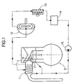
- FIG. 1 is a diagram showing the overall arrangement of a Rankine cycle system
- FIG. 2 is a vertical sectional view of the surroundings of a cylinder head of an internal combustion engine
- FIG. 3 is an enlarged view of a part 3 in FIG. 2
- FIG. 4 is a view from arrowed line 4-4 in FIG. 2
- FIG. 5 is a sectional view along line 5-5 in FIG. 4
- FIG. 6 is a sectional view along line 6-6 in FIG. 4
- FIG. 7 is a partially cutaway perspective view of an independent exhaust port
- FIG. 8 is a view from arrow 8 in FIG. 7
- FIG. 9 is a view from arrow 9 in FIG. 8
- FIG. 1 is a diagram showing the overall arrangement of a Rankine cycle system
- FIG. 2 is a vertical sectional view of the surroundings of a cylinder head of an internal combustion engine
- FIG. 3 is an enlarged view of a part 3 in
- FIG. 10 is a view from arrow 10 in FIG. 8;
- FIG. 11A and FIG. 11B are schematic views showing the flow of water in a grouped exhaust port;
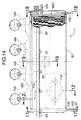
- FIG. 12 is an enlarged sectional view of an essential part in FIG. 2;
- FIG. 13 is a view from arrowed line 13-13 in FIG. 12;
- FIG. 14 is a view from arrow 14 in FIG. 12;
- FIG. 15 is a sectional view along line 15-15 in FIG. 12;
- FIG. 16 is an enlarged view of a part 16 in FIG. 15;
- FIG. 17 is a sectional view along line 17-17 in FIG. 14;
- FIG. 18 is a sectional view along line 18-18 in FIG. 14;
- FIG. 19 is a sectional view along line 19-19 in FIG. 14;
- FIG. 12 is an enlarged sectional view of an essential part in FIG. 2
- FIG. 13 is a view from arrowed line 13-13 in FIG. 12
- FIG. 14 is a view
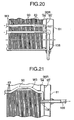
- FIG. 20 is a sectional view along line 20-20 in FIG. 12;
- FIG. 21 is a sectional view along line 21-21 in FIG. 12;
- FIG. 22 is a diagram showing the flow of water in a main evaporator; and
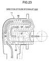
- FIG. 23 is a diagram showing the flow of exhaust gas in the main evaporator.
- FIG. 1 shows the overall arrangement of a Rankine cycle system to which the present invention is applied.
- the Rankine cycle system which recovers the thermal energy of an exhaust gas of an internal combustion engine E and converts it into mechanical energy, includes a main evaporator 11 that heats water with exhaust gas discharged from the internal combustion engine E so as to generate high temperature, high pressure steam, an expander 12 that is operated by the high temperature, high pressure steam generated by the main evaporator 11 so as to generate mechanical energy, a condenser 13 that cools decreased temperature, decreased pressure steam that has completed work in the expander 12 so as to turn it back into water, a reservoir tank 14 for collecting water discharged from the condenser 13, and a supply pump 15 for pressurizing the water collected in the reservoir tank 14.
- a portion of the water discharged from the supply pump 15 is supplied to the main evaporator 11, which is provided downstream of an exhaust port 16 of the internal combustion engine E, turns into high temperature, high pressure steam in the main evaporator 11, and is supplied to the expander 12, and the rest of water discharged from the supply pump 15 is heated while passing through an auxiliary evaporator 17 provided on the outer periphery of the exhaust port 16, and then merges into the main evaporator 11 at a predetermined position.
- the main evaporator 11 carries out heat exchange mainly with the exhaust gas discharged from the exhaust port 16 and generates steam, but the auxiliary evaporator 17 carries out heat exchange not only with the exhaust gas flowing through the exhaust port 16 but also with the exhaust port 16 itself, which is in contact with a high temperature exhaust gas, thus generating steam and simultaneously cooling the exhaust port 16.
- a cylinder head 20 and a head cover 21 are joined to a cylinder block 19 of the in-line four-cylinder internal combustion engine E, and four combustion chambers 24 are formed between the lower face of the cylinder head 20 and the upper face of each of four pistons 23 slidably fitted in four cylinder sleeves 22 housed in the cylinder block 19.
- Formed in the cylinder head 20 are intake ports 26 and exhaust ports 16, which communicate with the corresponding combustion chambers 24.
- An intake valve seat 27 at the downstream end of the intake port 26 is opened and closed by a head 28a of an intake valve 28, and an exhaust valve seat 29 at the upstream end of the exhaust port 16 is opened and closed by a head 30a of an exhaust valve 30.
- the exhaust port 16 is formed from four independent exhaust ports 16A and one grouped exhaust port 16B, each thereof being made of a member that is separate from the cylinder head 20 and fitted in the cylinder head 20.
- a single camshaft 31 Supported on the cylinder head 20 are a single camshaft 31, a single intake rocker arm shaft 32, and a single exhaust rocker arm shaft 33.
- One end of an intake rocker arm 34 rockably supported by the intake rocker arm shaft 32 abuts against an intake cam 35 provided on the camshaft 31, and the other end thereof abuts against a stem 28b of the intake valve 28, which is slidably supported by an intake valve guide 36 provided in the cylinder head 20 and is urged upward by a valve spring 37.
- an exhaust rocker arm 38 rockably supported by the exhaust rocker arm shaft 33 abuts against an exhaust cam 39 provided on the camshaft 31, and the other end thereof abuts against the upper end of a stem 30b of the exhaust valve 30, which is slidably supported by an exhaust valve guide 40 provided in the cylinder head 20 and is urged upward by a valve spring 41.
- the exhaust port 16 is formed from the four independent exhaust ports 16A, which are positioned on the upstream side of the flow of exhaust gas, and the single grouped exhaust port 16B, which communicates with the downstream side of the independent exhaust ports 16A, and an end portion on the upstream side of the main evaporator 11 is fitted into the inside of the grouped exhaust port 16B.
- the auxiliary evaporator 17 is provided so as to straddle the independent exhaust ports 16A and the grouped exhaust port 16B communicating with the downstream side thereof.
- the independent exhaust port 16A is formed from a first port member 51, a first cover member 52, a second port member 53, and a second cover member 54.
- the first port member 51 and the first cover member 52 form an upstream portion 55 of the independent exhaust port 16A that communicates with the combustion chamber 24, and have a structure in which the first port member 51, which is on the inside, is covered by the first cover member 52, which is on the outside, and a labyrinth-shaped water passage W2 is formed between the inner face of the first cover member 52 and a channel formed on the outer face of the first port member 51.
- the lower faces of the first port member 51 and the first cover member 52 abut against the upper face of the exhaust valve seat 29, which is formed in the cylinder head 20, via a seal 56.
- an opening 51 a through which the stem 30b of the exhaust valve 30 runs is formed in an upper wall of the first port member 51, and the lower end of the exhaust valve guide 40 is fitted via a seal 57 in an opening 52a formed on an upper wall of the first cover member 52.
- the second port member 53 and the second cover member 54 form a downstream portion 58 of the independent exhaust port 16A, which communicates with the grouped exhaust port 16B, and have a structure in which the second port member 53, which is on the inside, is covered by the second cover member 54, which is on the outside, and the labyrinth-shaped water passage W2 is formed between the inner face of the second cover member 54 and a channel formed on the outer face of the second port member 53.
- An end portion of the second cover member 54 is fitted in an opening 52b formed in a side face of the first cover member 52, thereby joining the first port member 51 and the second port member 53 smoothly so as to define a curved passage for the exhaust gas.
- the water passage W2 defined by the second port member 53 and the second cover member 54 includes a water inlet 59 on the lower side thereof and a water outlet 60 on the upper side thereof.
- the water passage W2 is formed with lateral symmetry relative to a plane of symmetry P1 of the independent exhaust port 16A; immediately after the water inlet 59 the water passage W2 branches into two lines so as to sandwich the plane of symmetry P1 and the two lines merge again immediately before the water outlet 60.
- the water passage W2 extends linearly from the water inlet 59 along a lower face of the downstream portion 58 (part a ), moves therefrom to the upstream portion 55, extends in a semicircular shape around the head 30a of the exhaust valve 30 (part b ), extends therefrom linearly upward along the stem 30b of the exhaust valve 30 up to the vicinity of the lower end of the exhaust valve guide 40 (part c ), extends therefrom toward the head 30a of the exhaust valve 30 while bent in a zigzag shape (part d ), returns therefrom back to the downstream portion 58, and extends toward the water outlet 60 while bent in a zigzag shape (part e ).
- the grouped exhaust port 16B includes a rectangular frame-shaped flange 61, and by tightening a plurality of bolts 62 running through a flange 11a of the main evaporator 11 to the cylinder head 20 the main evaporator 11 and the grouped exhaust port 16B are together secured to the cylinder head 20 (see FIG. 2).
- the downstream end of a pressed sheet material third port member 63 is welded to the flange 61 of the grouped exhaust port 16B, and four openings 63a formed in the upstream end of the third port member 63 communicate with exits of the four independent exhaust ports 16A.
- the downstream end of a pressed sheet material fourth port member 64 is welded to an inner face of the third port member 63, and the upstream end of the fourth port member 64 is superimposed on the four openings 63a of the third port member 63 and welded.
- the exhaust gases discharged from the four independent exhaust ports 16A are therefore merged in the grouped exhaust port 16B, and guided evenly to the main evaporator 11.
- Water passages W1 which are formed from a pipe material, are disposed in a space surrounded by the third port member 63 and the fourth port member 64 of the grouped exhaust port 16B. Since the water passages W1 have a symmetrical structure relative to a plane of symmetry P2, FIG. 4 to FIG. 6, FIG. 11 A, and FIG. 11B show the water passage W1 on one side of the plane of symmetry P2.
- the water passage W1 has a first line passing through the independent exhaust port 16A(1) on the side close to the plane of symmetry P2 and a second line passing through the independent exhaust port 16A(2) on the side far from the plane of symmetry P2.
- the water passage W1 starting at a water inlet 65 provided on an end portion of the flange 61 extends linearly along an inner face of the fourth port member 64 (part f ), and extends linearly therefrom along an inner face of the third port member 63 (part g ).
- a coupling 66 is provided in the part g, and the water inlet 59 of the independent exhaust port 16A(1) is connected to this coupling 66.
- the water passage W1 extending from a coupling 67 to which the water outlet 60 of the independent exhaust port 16A(1) is connected extends linearly along the inner face of the third port member 63 (part h ), extends therefrom along the inner face of the third port member 63 in a zigzag shape (part i ), extends linearly therefrom along the inner face of the third port member 63 (part i ) , turns downward through 90°, and communicates with the water outlet 68.
- the water outlet 68 communicates with an intermediate portion of the main evaporator 11 via a connecting pipe 106, which will be described later.
- the water passage W1 extending through the coupling 66 further extends along the inner face of the third port member 63 in a zigzag shape (part k ), extends linearly along the inner face of the fourth port member 64 (part m ), turns through 90°, extends linearly (part n ), further turns through 90°, extends linearly along the inner face of the third port member 63 (part o ), and is connected to the water inlet 59 of the independent exhaust port 16A(2) via a coupling 69 provided therein.
- a coupling 70 to which the water outlet 60 of the independent exhaust port 16A(2) is connected merges with the part j of the water passage W1.
- the main evaporator 11, which communicates with the downstream side of the auxiliary evaporator 17, has a casing 81 fixed to its flange 11a, the cross section of the casing 81 being substantially rectangular, and an exhaust exit 11b communicating with an exhaust pipe 82 (see FIG. 13) is formed on a lower face of the casing 81.
- a large number of thin metal heat transfer plates 83 are disposed parallel to each other at a predetermined pitch within the casing 81.
- An exhaust gas purification catalyst for cleaning up the exhaust gas is supported on the surface of all of the heat transfer plates 83.
- the heat transfer plate 83 is formed from a first heat transfer plate 83(1) and a second heat transfer plate 83(2) having plane-symmetric concavoconvex portions, and they are alternately superimposed.
- the first heat transfer plate 83(1) and the second heat transfer plate 83(2) thus make contact and are brazed to each other at abutment sections 84 and 85, and a partition wall 86 for blocking the circulation of exhaust gas is formed in this section.
- the partition wall 86 is arranged in the shape shown in FIG. 12, and forms a bent exhaust gas passage between adjacent heat transfer plates 83.
- the exhaust gas passage is formed from a first exhaust gas passage 87, a second exhaust gas passage 88, and a third exhaust gas passage 89, the first exhaust gas passage 87 communicating with the downstream end of the auxiliary evaporator 17 and extending linearly in a direction away from the cylinder head 20, the second exhaust gas passage 88 bending through 180° at the downstream end of the first exhaust gas passage 87 and extending linearly toward the cylinder head 20, and the third exhaust gas passage 89 bending through 180° at the downstream end of the second exhaust gas passage 88, extending in a direction away from the cylinder head 20, further bending through 90°, and extending downward so as to form an overall L-shape.
- an oxygen concentration sensor 91 is mounted on the middle of the lower face of the main evaporator 11, and a detection portion 91 a at the extremity thereof faces the first exhaust gas passage 87.
- an oxygen concentration sensor cooling portion 92 is provided on the lower face of the main evaporator 11 on which the oxygen concentration sensor 91 is mounted.
- a flat upper face of the oxygen concentration sensor cooling portion 92 faces the first exhaust gas passage 87 via the partition wall 86, and a lower face thereof faces the atmosphere via the casing 81.
- the oxygen concentration sensor cooling portion 92 includes a plurality of pipe members 93, which run through the heat transfer plates 83 and are joined thereto by brazing.
- left and right headers 96L and 96R are provided at longitudinally opposite ends of the casing 81 of the main evaporator 11, the left and right headers 96L and 96R being formed by integrally connecting inner plates 94 and outer plates 95 with a predetermined gap therebetween.
- Each of the headers 96L, 96R has the inner plate 94 thereof superimposed on the heat transfer plate 83 that is layered on the outermost side.
- a water inlet pipe 97 communicating with the downstream side of the supply pump 15 runs through a rear face of the casing 81 of the main evaporator 11, reaches the outer face of the outer plate 95 of the left-hand (when facing the cylinder head 20) header 96L, and is connected via a bifurcated coupling 98 to two of the pipe members 90 positioned at the downstream end of the third exhaust gas passage 89.
- the density of the pipe members 90 is the most sparse in the first exhaust gas passage 87, which is on the upstream side of the flow of exhaust gas, moderate in the second exhaust gas passage 88, which is in the middle, and the most dense in the third exhaust gas passage 89, which is on the downstream side.
- a water inlet pipe 100 communicating with the downstream side of the supply pump 15 runs through a rear face of the casing 81 of the main evaporator 11 and reaches an outer face of the outer plate 95 of the left-hand (when facing the cylinder head 20) header 96L, and is connected to two of the pipe members 93 via a bifurcated coupling 101.
- These two pipe members 93 form the beginning of two lines of water passages W4, and adjacent pipe members 93 of each line are connected via U-shaped couplings 102 in the left and right headers 96L and 96R and via five couplings 103 in a space surrounding the oxygen concentration sensor 91, thus forming the water passages W4 in a zigzag shape.
- the downstream ends of the two line water passages W4 communicate via couplings 104 and connecting pipes 105 with the water inlets 65 (see FIG. 5) of the auxiliary evaporator 17 formed within the flanges 11 a and 61.
- the two connecting pipes 106 communicating with the water outlets of the water passages W2 of the auxiliary evaporator 17 extend to the exterior of the casing 81 through the outside of the headers 96L and 96R, bend through 180°, re-enter the interior of the casing 81, and are connected to the pipe members 90 of the cooling water passages W3 via bifurcated couplings 107 provided in the headers 96L and 96R.
- the position of the pipe members 90 connected to the connecting pipes 106 is in the vicinity of the upstream end of the second exhaust gas passage 88 as shown by the reference numerals 90(1) and 90(2) in FIG. 22.
- the two pipe members 90 (shown by the reference numerals 90(3) and 90(4) in FIG. 22) positioned at the downstream end of the water passages W3 are connected via a bifurcated coupling 108 to a water outlet pipe 109 that communicates with the expander 12.
- a portion of the water discharged from the supply pump 15 of the Rankine cycle system is supplied to the main evaporator 11, which is provided downstream of the exhaust port 16 of the internal combustion engine E, and the rest of the water discharged from the supply pump 15 passes through the auxiliary evaporator 17 provided on the outer periphery of the exhaust port 16 and merges into the main evaporator 11 at a predetermined position.
- the operation in the main evaporator 11 is first explained.
- a portion of the low temperature water discharged from the supply pump 15 flows to the left header 96L of the casing 81 of the main evaporator 11 via the water inlet pipe 97 (see FIG. 15), and the flow is divided into the two lines of water passages W3 via the coupling 98.
- Each of the water passages W3 is formed from the large number of pipe members 90 connected in a zigzag shape, and carries out heat exchange with the exhaust gas passing through the gaps between the large number of heat transfer plates 83, through which the pipe members 90 run, thereby depriving the exhaust gas of thermal energy and increasing in temperature.
- the two pipe members 90 at the downstream end of the two lines of water passages W3 are merged with the water outlet pipe 109 (see FIG. 21) via the coupling 108.
- the water is heated and turns into high temperature, high pressure steam while flowing through the water passages W3, and is supplied to the expander 12.
- the heat of the exhaust gas is transferred from the large number of heat transfer plates 83, which have a large surface area and are arranged at a small pitch, to the water flowing through the large number of pipe members 90, it is possible to ensure that there is a sufficient area of heat exchange between the exhaust gas and the water. Accordingly, even when the flow rate of the exhaust gas is reduced, that is, when the cross-sectional area of the exhaust gas flow path in the main evaporator 11 is increased, sufficient heat exchange efficiency can be obtained, and suppressing an increase in the back pressure of the exhaust passage can prevent any decrease in the output of the internal combustion engine E.
- the partition wall 86 can be provided in any shape by forming only the abutment sections 84 and 85, and the first to third exhaust gas passages 87, 88, and 89, which are bent, can be formed without employing any special component for providing the partition wall 86.
- the density of the pipe members 90 is low in the first exhaust gas passage 87, which is on the upstream side of the flow of the exhaust gas, and the density of the pipe members 90 gradually increases therefrom toward the third exhaust gas passage 89, which is on the downstream side, by reducing the density of the pipe members 90 in the upstream section where the exhaust gas has a high temperature and a large volume and the flow rate is high it is possible to minimize the pressure loss due to impingement of the exhaust gas on the pipe members 90, and by increasing the density of the pipe members 90 in the downstream section where the exhaust gas has a low temperature and a small volume and the flow rate is low it is possible to ensure that there is sufficient contact between the exhaust gas and the pipe members 90 and improve the heat exchange efficiency.
- the exhaust gas purification catalyst is supported on the heat transfer plates 83, which have a large surface area, it is possible to ensure that the exhaust gas makes sufficient contact with the exhaust gas purification catalyst, thereby cleaning the exhaust gas effectively.
- the rest of the low temperature water discharged from the supply pump 15 enters the interior of the left-hand header 96L of the casing 81 of the main evaporator 11 via the water inlet pipe 100 (see FIG. 15), and the flow thereof is divided into the two lines of water passages W4 via the coupling 101.
- Water that has flowed in a zigzag shape through the interior of the pipe members 93 forming each of the water passages W4 is first merged in the H-shaped coupling 103 in the vicinity of the oxygen concentration sensor 91, is then divided again, further flows in a zigzag shape through the interior of the pipe members 93, then flows from the left and right headers 96L and 96R through the couplings 104, the connecting pipes 105, and the water inlets 65, and is then supplied to the auxiliary evaporator 17.
- the third exhaust gas passage 89 which is positioned on the downstream side of the flow of exhaust gas and to which water having the lowest temperature is supplied, is disposed in a radially outer portion of the main evaporator 11, and the oxygen concentration sensor cooling portion 92, to which water having the lowest temperature is supplied, is disposed in a radially outer portion of the main evaporator 11, that is, since the outsides of the first exhaust gas passage 87 and the second exhaust gas passage 88, which reach a high temperature due to the passage of high temperature exhaust gas, are surrounded by the third exhaust gas passage 89 and the oxygen concentration sensor cooling portion 92, which reach a low temperature due to the passage of low temperature water, it is possible to minimize the dissipation of thermal energy to the outside of the main evaporator 11,
- a gap that maintains an air layer is formed between the inner periphery of the casing 81 and the outer periphery of the heat transfer plates 83, and the heat insulating effect of this air layer can further reduce the dissipation of thermal energy to the outside of the main evaporator 11.
- FIG. 11A and FIG. 11B water discharged from the oxygen concentration sensor cooling portion 92 flows into the water passage W1 from the water inlet 65 of the grouped exhaust port 16B and the flow is divided into the first line and the second line.
- the first line shown in FIG. 11 A has a route that reaches the water outlet 68 via the part f and the part g of the water passage W1, the coupling 66, the water passage W2 of the independent exhaust port 16A(1), the coupling 67, and the part h , the part i , and the part j of the water passage W1.
- 11 B has a route that reaches the water outlet 68 via the part f , the part g , the part k , the part m , the part n , and the part o of the water passage W1, the coupling 69, the water passage W2 of the independent exhaust port 16A(2), and the part j of the water passage W1. Since in the first line the first half of the water passage W1 is short and the second half thereof is long, and in the second line the first half of the water passage W1 is long and the second half thereof is short, the overall length of the water passage W1 in the two lines is equalized, thus making the amount supplied substantially equal, preventing an imbalance in the waste heat recovery, and improving the heat exchange efficiency.
- the structures of the water passages W2 provided in the two independent exhaust ports 16A(1) and 16A(2) are identical, and water supplied from the water inlet 59 branches so as to sandwich the plane of symmetry P1, passes through the part a , the part b , the part c , the part d , and the part e , is merged, and is then discharged via the water outlet 60.
- the auxiliary evaporator 17 is arranged so that the surroundings of the exhaust port 16, which reach a high temperature due to the passage of exhaust gas, are surrounded by the water passages W1 and W2, the exhaust gas heat dissipated from the exhaust port 16 via the cylinder head 20 can be recovered effectively as high temperature, high pressure steam.
- the water supplied to the water passages W1 and W2 is comparatively low temperature water that has only passed through the oxygen concentration sensor cooling portion 92 after being discharged from the supply pump 15, the surroundings of the exhaust port 16 can be cooled effectively, and high temperature, high pressure steam can be generated, thus enhancing the waste heat recovery effect of the internal combustion engine E.
- the heat of exhaust gas easily escapes to the outside via the exhaust valve 30, intensive cooling, with low temperature water, of the section that requires cooling of the internal combustion engine E, that is, the exhaust valve seat 29, with which the head 30a of the exhaust valve 30 makes contact, and the vicinity of the exhaust valve guide 40, with which the stem 30b of the exhaust valve 30 makes contact, enables the escape of heat via the exhaust valve 30 to be suppressed, thus further enhancing the waste heat recovery effect, and enables thermal expansion of the exhaust valve 30, the exhaust valve seat 29, and the exhaust valve guide 40, etc. to be suppressed, thus maintaining dimensional and positional precision and thereby maintaining desired functions thereof.
- Water that has passed through the auxiliary evaporator 17 passes from the connecting pipes 106 (see FIG. 17 and FIG. 18) through the couplings 107 (see FIG. 20) provided in the left and right headers 96L and 96R, and is merged in the pipe members 90 of the second exhaust gas passage 88 of the main evaporator 11.
- the waste heat recovery effect can be further improved.
- This control of water temperature can be carried out by regulating the flow rate ratio when splitting the flow of water discharged from the supply pump 15 into the main evaporator 11 side and the auxiliary evaporator 17 side.
- the heat exchanger is exemplified by the main evaporator 11, but the heat exchanger of the present invention is not limited to an evaporator.
- water is illustrated as the heat medium, but the heat medium of the present invention is not limited to water.
- the present invention can be suitably applied to an evaporator for a Rankine cycle system and, in particular, to an evaporator for a Rankine cycle system that recovers the thermal energy of the exhaust gas of an internal combustion engine of an automobile and converts it into mechanical energy
- the present invention can also be applied to a heat exchanger for any purpose.
Landscapes
- Engineering & Computer Science (AREA)
- Chemical & Material Sciences (AREA)
- Combustion & Propulsion (AREA)
- Mechanical Engineering (AREA)
- General Engineering & Computer Science (AREA)
- Life Sciences & Earth Sciences (AREA)
- Sustainable Development (AREA)
- Sustainable Energy (AREA)
- Physics & Mathematics (AREA)
- Thermal Sciences (AREA)
- Heat-Exchange Devices With Radiators And Conduit Assemblies (AREA)
- Exhaust Gas After Treatment (AREA)
Applications Claiming Priority (3)
| Application Number | Priority Date | Filing Date | Title |
|---|---|---|---|
| JP2001356653 | 2001-11-21 | ||
| JP2001356653A JP3730903B2 (ja) | 2001-11-21 | 2001-11-21 | 熱交換器 |
| PCT/JP2002/011470 WO2003044342A1 (fr) | 2001-11-21 | 2002-11-01 | Echangeur de chaleur |
Publications (1)
| Publication Number | Publication Date |
|---|---|
| EP1447537A1 true EP1447537A1 (en) | 2004-08-18 |
Family
ID=19168140
Family Applications (1)
| Application Number | Title | Priority Date | Filing Date |
|---|---|---|---|
| EP02775477A Withdrawn EP1447537A1 (en) | 2001-11-21 | 2002-11-01 | Heat exchanger |
Country Status (4)
| Country | Link |
|---|---|
| US (1) | US6907734B2 (ja) |
| EP (1) | EP1447537A1 (ja) |
| JP (1) | JP3730903B2 (ja) |
| WO (1) | WO2003044342A1 (ja) |
Families Citing this family (10)
| Publication number | Priority date | Publication date | Assignee | Title |
|---|---|---|---|---|
| JP2002097946A (ja) * | 2000-09-25 | 2002-04-05 | Honda Motor Co Ltd | 内燃機関の廃熱回収装置 |
| JP3730904B2 (ja) * | 2001-11-21 | 2006-01-05 | 本田技研工業株式会社 | 熱交換装置 |
| US7721543B2 (en) * | 2006-10-23 | 2010-05-25 | Southwest Research Institute | System and method for cooling a combustion gas charge |
| US8776522B2 (en) * | 2008-04-15 | 2014-07-15 | Morningside Venture Investments Limited | Water reclamation system and method |
| US20100083919A1 (en) * | 2008-10-03 | 2010-04-08 | Gm Global Technology Operations, Inc. | Internal Combustion Engine With Integrated Waste Heat Recovery System |
| US7827814B2 (en) * | 2009-08-12 | 2010-11-09 | Hal Slater | Geothermal water heater |
| US20110185726A1 (en) * | 2010-02-04 | 2011-08-04 | Cleanpower Technology, Inc. | Energy separation and recovery system for mobile application |
| US8628025B2 (en) * | 2010-03-09 | 2014-01-14 | GM Global Technology Operations LLC | Vehicle waste heat recovery system and method of operation |
| US10428713B2 (en) | 2017-09-07 | 2019-10-01 | Denso International America, Inc. | Systems and methods for exhaust heat recovery and heat storage |
| CN108495539A (zh) * | 2018-06-03 | 2018-09-04 | 东莞昂湃实业有限公司 | 一种整合式的液冷散热系统 |
Family Cites Families (9)
| Publication number | Priority date | Publication date | Assignee | Title |
|---|---|---|---|---|
| JPS5642090A (en) * | 1979-09-12 | 1981-04-20 | Nissan Motor Co Ltd | Heat exchanger |
| CN1003053B (zh) * | 1985-05-24 | 1989-01-11 | 三菱电机株式会社 | 热交换器 |
| DE4205240A1 (de) * | 1992-02-21 | 1993-08-26 | Porsche Ag | Antriebsaggregat, insbesondere fuer kraftfahrzeuge |
| JP3232181B2 (ja) * | 1993-12-09 | 2001-11-26 | ヤンマーディーゼル株式会社 | エンジン駆動ヒートポンプ及び駆動用エンジン |
| JPH10206067A (ja) * | 1997-01-27 | 1998-08-07 | Honda Motor Co Ltd | 熱交換器の支持構造 |
| US6374910B2 (en) * | 1997-01-27 | 2002-04-23 | Honda Giken Kogyo Kabushiki Kaisha | Heat exchanger |
| JP4229559B2 (ja) | 2000-01-21 | 2009-02-25 | 本田技研工業株式会社 | 多気筒内燃機関の熱交換装置 |
| JP4229560B2 (ja) | 2000-01-21 | 2009-02-25 | 本田技研工業株式会社 | 熱交換器 |
| JP2001289042A (ja) * | 2000-04-03 | 2001-10-19 | Denso Corp | 排熱回収装置 |
-
2001
- 2001-11-21 JP JP2001356653A patent/JP3730903B2/ja not_active Expired - Fee Related
-
2002
- 2002-11-01 WO PCT/JP2002/011470 patent/WO2003044342A1/ja not_active Application Discontinuation
- 2002-11-01 US US10/496,073 patent/US6907734B2/en not_active Expired - Fee Related
- 2002-11-01 EP EP02775477A patent/EP1447537A1/en not_active Withdrawn
Non-Patent Citations (1)
| Title |
|---|
| See references of WO03044342A1 * |
Also Published As
| Publication number | Publication date |
|---|---|
| JP2003155928A (ja) | 2003-05-30 |
| WO2003044342A1 (fr) | 2003-05-30 |
| US20050050890A1 (en) | 2005-03-10 |
| US6907734B2 (en) | 2005-06-21 |
| JP3730903B2 (ja) | 2006-01-05 |
Similar Documents
| Publication | Publication Date | Title |
|---|---|---|
| US7069884B2 (en) | Internal combustion engine | |
| US7191740B2 (en) | Internal combustion engine | |
| US7077190B2 (en) | Exhaust gas heat exchanger | |
| EP1455062B1 (en) | Heat exchange device | |
| US20050087154A1 (en) | Cylinder head with integrated exhaust manifold | |
| US10697706B2 (en) | Heat exchanger | |
| US6907734B2 (en) | Heat exchanger | |
| EP1455061B1 (en) | Heat exchange device | |
| US7069977B2 (en) | Heat exchanger | |
| KR101009391B1 (ko) | 다단 스털링 기관 | |
| US20090084532A1 (en) | Heat exchanger with divided coolant chamber | |
| US20050103484A1 (en) | Heat exchanger | |
| JP2006083725A (ja) | 排気熱発電装置 | |
| KR20110042914A (ko) | 태양열발전시스템의 스터링 엔진용 인쇄형 열교환식 흡수기 | |
| JP2001303953A (ja) | エンジンの冷却構造 | |
| Hughes et al. | Heat exchanger | |
| KR20240059989A (ko) | 히트펌프형 방열유닛 및 그 제조방법 | |
| KR20240032561A (ko) | 열전발전 열교환장치 | |
| JPH0341043Y2 (ja) | ||
| JP2010203732A (ja) | 排気熱回収装置 |
Legal Events
| Date | Code | Title | Description |
|---|---|---|---|
| PUAI | Public reference made under article 153(3) epc to a published international application that has entered the european phase |
Free format text: ORIGINAL CODE: 0009012 |
|
| 17P | Request for examination filed |
Effective date: 20040519 |
|
| AK | Designated contracting states |
Kind code of ref document: A1 Designated state(s): AT BE BG CH CY CZ DE DK EE ES FI FR GB GR IE IT LI LU MC NL PT SE SK TR |
|
| STAA | Information on the status of an ep patent application or granted ep patent |
Free format text: STATUS: THE APPLICATION IS DEEMED TO BE WITHDRAWN |
|
| 18D | Application deemed to be withdrawn |
Effective date: 20070701 |