EP1447485A2 - Draining device - Google Patents
Draining device Download PDFInfo
- Publication number
- EP1447485A2 EP1447485A2 EP03029682A EP03029682A EP1447485A2 EP 1447485 A2 EP1447485 A2 EP 1447485A2 EP 03029682 A EP03029682 A EP 03029682A EP 03029682 A EP03029682 A EP 03029682A EP 1447485 A2 EP1447485 A2 EP 1447485A2
- Authority
- EP
- European Patent Office
- Prior art keywords
- drain
- pipe
- holding element
- valve element
- cup
- Prior art date
- Legal status (The legal status is an assumption and is not a legal conclusion. Google has not performed a legal analysis and makes no representation as to the accuracy of the status listed.)
- Granted
Links
Images
Classifications
-
- E—FIXED CONSTRUCTIONS
- E03—WATER SUPPLY; SEWERAGE
- E03C—DOMESTIC PLUMBING INSTALLATIONS FOR FRESH WATER OR WASTE WATER; SINKS
- E03C1/00—Domestic plumbing installations for fresh water or waste water; Sinks
- E03C1/12—Plumbing installations for waste water; Basins or fountains connected thereto; Sinks
- E03C1/26—Object-catching inserts or similar devices for waste pipes or outlets
- E03C1/264—Separate sieves or similar object-catching inserts
-
- E—FIXED CONSTRUCTIONS
- E03—WATER SUPPLY; SEWERAGE
- E03C—DOMESTIC PLUMBING INSTALLATIONS FOR FRESH WATER OR WASTE WATER; SINKS
- E03C1/00—Domestic plumbing installations for fresh water or waste water; Sinks
- E03C1/12—Plumbing installations for waste water; Basins or fountains connected thereto; Sinks
- E03C1/22—Outlet devices mounted in basins, baths, or sinks
-
- E—FIXED CONSTRUCTIONS
- E03—WATER SUPPLY; SEWERAGE
- E03C—DOMESTIC PLUMBING INSTALLATIONS FOR FRESH WATER OR WASTE WATER; SINKS
- E03C1/00—Domestic plumbing installations for fresh water or waste water; Sinks
- E03C1/12—Plumbing installations for waste water; Basins or fountains connected thereto; Sinks
- E03C1/28—Odour seals
- E03C1/298—Odour seals consisting only of non-return valve
-
- F—MECHANICAL ENGINEERING; LIGHTING; HEATING; WEAPONS; BLASTING
- F16—ENGINEERING ELEMENTS AND UNITS; GENERAL MEASURES FOR PRODUCING AND MAINTAINING EFFECTIVE FUNCTIONING OF MACHINES OR INSTALLATIONS; THERMAL INSULATION IN GENERAL
- F16K—VALVES; TAPS; COCKS; ACTUATING-FLOATS; DEVICES FOR VENTING OR AERATING
- F16K15/00—Check valves
- F16K15/14—Check valves with flexible valve members
- F16K15/144—Check valves with flexible valve members the closure elements being fixed along all or a part of their periphery
- F16K15/147—Check valves with flexible valve members the closure elements being fixed along all or a part of their periphery the closure elements having specially formed slits or being of an elongated easily collapsible form
Definitions
- the invention relates in particular to a urinal, bidet, washstand or the same particular drain device, which in the drain pipe, in particular a goblet is installed by means of an annular holding element and consists of an elastic valve element that in the normal state gas-tight abutting wall sections the exit of prevents odor-laden gases from the drain system and in the event of Liquid that gets into a funnel-shaped inlet of the valve element in the Area of the adjacent wall sections due to the gravity of the Liquid is expanded and the liquid can escape.
- Such drainage devices are for example from GB 2 296 309 A. known.
- the invention has for its object to arrange the valve element easily replaceable and secure against damage from objects.
- the solution to this problem by the invention is characterized in that the annular holding element is held by means of a clamp seat in the drain pipe, in particular in the drain cup.
- valve element can be easily and quickly to be replaced. It is also possible to insert the valve element in existing drain lines from urinals, bidets, wash basins or the like use so that on the arrangement of an elaborate odor trap can be dispensed with.
- the press fit is achieved formed an elastic sealing ring.
- the ring-shaped Holding element covering the funnel-shaped inlet of the valve element Sieve to be attached.
- drain pipe To connect the clamp seat to the drain cup releasably, preferably with the help of a seal inserted in an annular groove.
- the drain pipe can be cut to length or be provided with a discharge sheet.
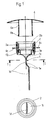
- the drain device shown as an individual part in Fig. 1 comprises a valve element 1, which is detachably inserted into an annular holding element 2.
- the valve element 1 consists of elastic material, for example suitable plastic.
- On an annular edge 1a is formed at its upper end. With this edge 1a, if necessary with the help of a separate O-ring, will Valve element 1 detachably fastened in the holding element 2.
- the upper, annular edge 1a is included Ring section 1b, which merges into a funnel-shaped inlet 1c. While this funnel-shaped inlet 1c has a circular cross section at the upper end , it ends at the lower end in a rectangular cross section, the Wall sections rest against each other due to the elasticity of the material. With this rectangular cross-section, the wall sections of which are normally rest against each other, the funnel-shaped inlet 1c goes into the actual one Valve area 1d over. In the exemplary embodiment, this valve area extends 1d over a greater length and includes two bends 1e.
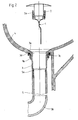
- Valve element 1 is a by means of the holding element 2 in the drain cup 3 sanitary ceramic object, for example a urinal, releasably attached, like the fig. 2 and 3 show.
- Holding element 2 is provided with an elastic sealing ring 2a, which is in an annular groove is inserted on the outer lateral surface of the holding element 2 and partially out protrudes from this surface.
- the upper end of the drain bowl 3 is with a conical extension 3a, with which it is in the course of a sanitary ceramic object 4 is used sealingly.
- the drain cup 3 is provided at the upper end with an external thread 3b, so that it can be replaced by a corresponding nut 3c with the interposition of an O-ring 3d at the end of the sanitary ceramic object 4 is sealed sealed.
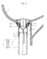
- a drain pipe 5 is connected opens into the drainage system of the sanitary ceramic object 4 without between the drain pipe 5 and the drain system a water-holding Pipe bend or another odor trap is arranged.
- the drain pipe 5 is releasably by means of a clamp seat formed by a seal 5a Drain cup 3 attached.
- the seal 5a is inserted into a conical annular groove. It can be cut to length from a longer piece of pipe or with a Drain bend 5b.
- valve element 1 In the normal state, the valve element 1 is closed odor-tight in that its wall sections rest against each other in the valve area 1d. The valve element 1, however, allows liquid to pass through the valve area 1d, when liquid enters the funnel-shaped inlet 1c and the normally adjacent wall sections of the valve area 1d expand due to the gravity of the liquid. In this way, a Leakage of the liquid from the valve element 1 allows, the Valve element 1 closes again immediately when the liquid Valve area 1d has left.
- the funnel-shaped inlet 1c of the valve element 1 covered by a sieve 6, which is provided with a pipe section 6a, over the the screen 6 is releasably attached to the holding element 2.
- the embodiment is the lower end of the pipe section 6a with resilient Provide locking tabs 6b, which snap into a groove 2b of the holding element 2 and fix the sieve 6 on the holding element 2.
- the pipe section 6a is also as Perforated element.
Landscapes
- Engineering & Computer Science (AREA)
- Environmental & Geological Engineering (AREA)
- Health & Medical Sciences (AREA)
- Life Sciences & Earth Sciences (AREA)
- Hydrology & Water Resources (AREA)
- Public Health (AREA)
- Water Supply & Treatment (AREA)
- General Engineering & Computer Science (AREA)
- Mechanical Engineering (AREA)
- Sink And Installation For Waste Water (AREA)
- Sanitary Device For Flush Toilet (AREA)
- Self-Closing Valves And Venting Or Aerating Valves (AREA)
Abstract
Description
Die Erfindung betrifft eine insbesondere für ein Urinal, Bidet, Waschtisch oder dergleichen bestimmte Ablaufeinrichtung, die in das Abflußrohr, insbesondere einen Ablaufkelch, mittels eines ringförmigen Halteelements eingebaut wird und aus einem elastischen Ventilelement besteht, das im Normalzustand durch gasdicht aneinander anliegende Wandabschnitte den Austritt von geruchsbelasteten Gasen aus dem Ablaufsystem verhindert und bei Anfall von Flüssigkeit, die in einen trichterförmigen Einlauf des Ventilelements gelangt, im Bereich der aneinander liegenden Wandabschnitte aufgrund der Schwerkraft der Flüssigkeit aufgeweitet wird und den Austritt der Flüssigkeit ermöglicht.The invention relates in particular to a urinal, bidet, washstand or the same particular drain device, which in the drain pipe, in particular a goblet is installed by means of an annular holding element and consists of an elastic valve element that in the normal state gas-tight abutting wall sections the exit of prevents odor-laden gases from the drain system and in the event of Liquid that gets into a funnel-shaped inlet of the valve element in the Area of the adjacent wall sections due to the gravity of the Liquid is expanded and the liquid can escape.
Derartige Ablaufeinrichtungen sind beispielsweise aus der GB 2 296 309 A
bekannt.Such drainage devices are for example from
Ausgehend von dieser bekannten Ausführungsform liegt der Erfindung die Aufgabe zugrunde, das Ventilelement leicht auswechselbar anzuordnen und gegen Beschädigung durch Gegenstände zu sichern.Based on this known embodiment, the invention has for its object to arrange the valve element easily replaceable and secure against damage from objects.
Die Lösung dieser Aufgabenstellung durch die Erfindung ist dadurch gekennzeichnet, daß das ringförmige Halteelement mittels eines Klemmsitzes im Abflußrohr, insbesondere im Ablaufkelch, gehalten ist.The solution to this problem by the invention is characterized in that the annular holding element is held by means of a clamp seat in the drain pipe, in particular in the drain cup.
Durch die Gestaltung des Halteringes und seine lösbare Befestigung im Abflußrohr mittels eines Klemmsitzes kann das Ventilelement einfach und schnell ausgewechselt werden. Außerdem ist es möglich, das Ventilelement auch in vorhandene Abflußleitungen von Urinalen, Bidets, Waschtischen oder dergleichen einzusetzen, so daß auf die Anordnung eines aufwendigen Geruchsverschlusses verzichtet werden kann.Through the design of the retaining ring and its detachable attachment in the drain pipe by means of a clamp seat, the valve element can be easily and quickly to be replaced. It is also possible to insert the valve element in existing drain lines from urinals, bidets, wash basins or the like use so that on the arrangement of an elaborate odor trap can be dispensed with.
Bei einer bevorzugten Ausführungsform der Erfindung wird der Klemmsitz durch einen elastischen Dichtring gebildet. Mit dieser Ausbildung ergibt sich eine besonders einfache Ausgestaltung, zumal der elastische Dichtring auf einfache Weise ausgewechselt werden kann.In a preferred embodiment of the invention, the press fit is achieved formed an elastic sealing ring. With this training there is a Particularly simple design, especially since the elastic sealing ring is simple Way can be replaced.
Gemäß einem weiteren Merkmal der Erfindung kann am ringförmigen Halteelement ein den trichterförmigen Einlauf des Ventilelements abdeckendes Sieb befestigt werden. Dieses einfach anzubringende Sieb ergibt einen guten Schutz des Ventilelements gegen Beschädigungen durch in den trichterförmigen Einlauf gelangende Gegenstände.According to a further feature of the invention, the ring-shaped Holding element covering the funnel-shaped inlet of the valve element Sieve to be attached. This easy-to-install strainer makes a good one Protection of the valve element against damage caused by funnel-shaped Objects arriving.
Mit der Erfindung wird weiterhin vorgeschlagen, das Sieb mittels eines Rohrstückes am Halteelement zu befestigen, das mit einer lösbaren Verrastung versehen ist. Hierdurch wird der Aufbau der Ablaufeinrichtung und ihre Benutzung weiter vereinfacht. Auch das Rohrstück kann als Sieb oder Lochelement ausgeführt werden.With the invention it is further proposed to use a sieve To fix the piece of pipe on the holding element, with a releasable locking is provided. As a result, the structure of the drain device and its use further simplified. The pipe section can also be used as a sieve or perforated element be carried out.
Mit der Erfindung wird schließlich vorgeschlagen, auch das Abflußrohr mittels Klemmsitz mit dem Ablaufkelch lösbar zu verbinden, vorzugsweise mit Hilfe einer in eine Ringnut eingelegten Dichtung. Das Abflußrohr kann ablängbar sein bzw. mit einem Ablaufbogen versehen werden.Finally, with the invention it is proposed to also use the drain pipe To connect the clamp seat to the drain cup releasably, preferably with the help of a seal inserted in an annular groove. The drain pipe can be cut to length or be provided with a discharge sheet.
Auf der Zeichnung ist ein Ausführungsbeispiel der erfindungsgemäßen Ablaufeinrichtung dargestellt, und zwar zeigt:
- Fig. 1
- einen senkrechten Schnitt durch die Ablaufeinrichtung,
- Fig. 2
- eine Schnittdarstellung vor dem Einbau der Ablaufeinrichtung in den Ablauf eines sanitärkeramischen Gegenstandes und
- Fig. 3
- einen der Fig. 2 entsprechenden Schnitt nach dem Einbau der Ablaufeinrichtung.
- Fig. 1
- a vertical section through the drain device,
- Fig. 2
- a sectional view before installing the drain device in the drain of a sanitary ceramic object and
- Fig. 3
- a section corresponding to FIG. 2 after installation of the drain device.
Die als Einzelteil in Fig. 1 dargestellte Ablaufeinrichtung umfaßt ein Ventilelement
1, das lösbar in ein ringförmiges Halteelement 2 eingesetzt ist. Das Ventilelement 1
besteht aus elastischem Material, beispielsweise geeignetem Kunststoff. An
seinem oberen Ende ist ein ringförmiger Rand 1a ausgebildet. Mit diesem Rand
1a, gegebenenfalls unter Zuhilfenahme eines separaten O-Ringes, wird das
Ventilelement 1 im Halteelement 2 lösbar befestigt.The drain device shown as an individual part in Fig. 1 comprises a
An den oberen, ringförmigen Rand 1a schließt sich beim Ausführungsbeispiel ein
Ringabschnitt 1b an, der in einen trichterförmigen Einlauf 1c übergeht. Während
dieser trichterförmige Einlauf 1c am oberen Ende einen kreisförmigen Querschnitt
hat, endet er am unteren Ende in einem rechteckigen Querschnitt, dessen
Wandabschnitte aneinander aufgrund der Elastizität des Werkstoffes anliegen. Mit
diesem rechteckigen Querschnitt, dessen Wandabschnitte im Normalfall
aneinander anliegen, geht der trichterförmige Einlauf 1c in den eigentlichen
Ventilbereich 1d über. Beim Ausführungsbeispiel erstreckt sich dieser Ventilbereich
1d über eine größere Länge und schließt zwei Abwinklungen 1e ein.In the exemplary embodiment, the upper,
Das in einer ringförmigen Ausnehmung des Halteelements 2 lösbar befestigte
Ventilelement 1 wird mittels des Halteelements 2 im Ablaufkelch 3 eines
sanitärkeramischen Gegenstandes, beispielsweise eines Urinals, lösbar befestigt,
wie die Fign. 2 und 3 zeigen. Zur Erzielung eines Klemmsitzes ist das
Halteelement 2 mit einem elastischen Dichtring 2a versehen, der in eine Ringnut
auf der äußeren Mantelfläche des Halteelements 2 eingelegt ist und teilweise aus
dieser Oberfläche hervorsteht. Der Einsatz der aus Ventilelement 1 und
Halteelement 2 bestehenden Ablaufeinrichtung kann auf diese Weise ohne
Werkzeuge und jederzeit lösbar im Ablaufkelch 3 erfolgen.The one detachably fastened in an annular recess of the
Beim Ausführungsbeispiel ist das obere Ende des Ablaufkelches 3 mit einer
konischen Erweiterung 3a ausgebildet, mit der es in den Ablauf eines
sanitärkeramischen Gegenstandes 4 dichtend eingesetzt wird. Der Ablaufkelch 3
ist am oberen Ende mit einem Außengewinde 3b versehen, so daß er durch eine
entsprechende Mutter 3c unter Zwischenfügen eines O-Ringes 3d am Ablauf des
sanitärkeramischen Gegenstandes 4 abgedichtet befestigt wird.In the embodiment, the upper end of the
An das untere Ende des Ablaufkelches 3 ist ein Abflußrohr 5 angeschlossen, das
im Abflußsystem des sanitärkeramischen Gegenstandes 4 mündet, ohne daß
zwischen dem Abflußrohr 5 und dem Abflußsystem ein wasserhaltender
Rohrbogen oder ein anderer Geruchverschluß angeordnet ist. Das Abflußrohr 5
wird mittels eines durch eine Dichtung 5a gebildeten Klemmsitzes lösbar am
Ablaufkelch 3 befestigt. Die Dichtung 5a ist in eine konische Ringnut eingelegt. Es
kann von einem längeren Rohrstück abgelängt werden oder mit einem
Ablaufbogen 5b versehen sein.At the lower end of the
Im Normalzustand ist das Ventilelement 1 dadurch geruchsdicht verschlossen, daß
seine Wandabschnitte im Ventilbereich 1d aneinander anliegen. Das Ventilelement
1 ermöglicht allerdings den Durchtritt von Flüssigkeit durch den Ventilbereich 1d,
wenn Flüssigkeit in den trichterförmigen Einlauf 1c eintritt und sich die
normalerweise aneinander anliegenden Wandabschnitte des Ventilbereiches 1d
aufgrund der Schwerkraft der Flüssigkeit aufweiten. Auf diese Weise wird ein
Austritt der Flüssigkeit aus dem Ventilelement 1 ermöglicht, wobei das
Ventilelement 1 unverzüglich wieder schließt, wenn die Flüssigkeit den
Ventilbereich 1d verlassen hat.In the normal state, the
Auf diese Weise ist es möglich, beispielsweise ein Urinal ohne Spülung mit Wasser zu betreiben bzw. bei anderen sanitärkeramischen Gegenständen, wie beispielsweise Bidets oder Waschtischen, auf aufwendige Geruchsverschlüsse mit wasserhaltenden Teilen zu verzichten.In this way it is possible, for example, a urinal without flushing with water to operate or with other sanitary ceramic objects, such as for example bidets or washstands, with elaborate odor traps dispense with water-containing parts.
Beim Ausführungsbeispiel wird der trichterförmige Einlauf 1c des Ventilelementes 1
durch ein Sieb 6 abgedeckt, das mit einem Rohrstück 6a versehen ist, über das
das Sieb 6 am Halteelement 2 lösbar befestigt wird. Beim dargestellten
Ausführungsbeispiel ist das untere Ende des Rohrstückes 6a mit federnden
Rastzungen 6b versehen, die in eine Nut 2b des Halteelements 2 einrasten und
das Sieb 6 am Halteelement 2 festlegen. Durch auf die federnden Rastzungen 6b
einwirkende Stifte 6c kann die Rastwirkung aufgehoben und das Rohrstück 6a aus
dem Halteelement 2 entfernt werden. Das Rohrstück 6a ist ebenfalls als
Lochelement ausgebildet. In the exemplary embodiment, the funnel-
- 11
- Ventilelementvalve element
- 1a1a
- Randedge
- 1b1b
- Ringabschnittring section
- 1c1c
- Einlaufenema
- 1d1d
- Ventilbereichvalve area
- 1e1e
- Abwinklungangling
- 22
- Halteelementretaining element
- 2a2a
- Dichtringseal
- 2b2 B
- Nutgroove
- 33
- Ablaufkelchdrain cup
- 3a3a
- Erweiterungextension
- 3b3b
- Außengewindeexternal thread
- 3c3c
- Muttermother
- 3d3d
- O-RingO-ring
- 44
- sanitärkeramischer Gegenstandsanitary ceramic object
- 55
- Abflußrohrwaste pipe
- 5a5a
- Dichtungpoetry
- 5b5b
- Ablaufbogenwaste pipe
- 66
- Siebscree
- 6a6a
- Rohrstückpipe section
- 6b6b
- Rastzungecatch tongue
- 6c6c
- Stiftpen
Claims (8)
dadurch gekennzeichnet, daß das ringförmige Halteelement (2) mittels eines Klemmsitzes im Abflußrohr (5), insbesondere Ablaufkelch (3), gehalten ist.Drain device, in particular for a urinal, bidet, wash basin or the like, which is installed in the drain pipe (5), in particular the drain cup (3), by means of an annular holding element (2) and consists of an elastic valve element (1) which is in the normal state by gas-tight abutting wall sections prevents odor-laden gases from escaping from the drain system and, in the event of liquid accumulating in a funnel-shaped inlet (1c) of the valve element (1), the area of the adjoining wall sections is expanded due to the gravity of the liquid and the Leakage of the liquid allows
characterized in that the annular holding element (2) is held in the drain pipe (5), in particular the drain cup (3), by means of a clamp fit.
Applications Claiming Priority (2)
| Application Number | Priority Date | Filing Date | Title |
|---|---|---|---|
| DE20302114U | 2003-02-11 | ||
| DE20302114U DE20302114U1 (en) | 2003-02-11 | 2003-02-11 | off device |
Publications (3)
| Publication Number | Publication Date |
|---|---|
| EP1447485A2 true EP1447485A2 (en) | 2004-08-18 |
| EP1447485A3 EP1447485A3 (en) | 2006-04-26 |
| EP1447485B1 EP1447485B1 (en) | 2013-07-31 |
Family
ID=7979910
Family Applications (1)
| Application Number | Title | Priority Date | Filing Date |
|---|---|---|---|
| EP20030029682 Expired - Lifetime EP1447485B1 (en) | 2003-02-11 | 2003-12-23 | Draining device |
Country Status (3)
| Country | Link |
|---|---|
| EP (1) | EP1447485B1 (en) |
| DE (1) | DE20302114U1 (en) |
| PL (1) | PL209265B1 (en) |
Cited By (4)
| Publication number | Priority date | Publication date | Assignee | Title |
|---|---|---|---|---|
| DE102009010862A1 (en) * | 2009-02-27 | 2010-09-02 | Airbus Deutschland Gmbh | Odor trap for a vacuum toilet drainage system |
| EP2447131A3 (en) * | 2010-10-26 | 2012-09-19 | Evac GmbH | Valve assembly for the removal of a liquid medium and method for controlling a valve assembly |
| EP2840191A1 (en) | 2013-08-21 | 2015-02-25 | Geberit International AG | Odour trap device |
| AU2013232928B2 (en) * | 2012-03-13 | 2016-08-11 | Ecosh Co., Ltd. | Waterless urinal |
Families Citing this family (8)
| Publication number | Priority date | Publication date | Assignee | Title |
|---|---|---|---|---|
| EP1614816B1 (en) * | 2004-07-09 | 2013-04-17 | Geberit International AG | Overflow and outlet device for sanitary apparatus |
| GB0920084D0 (en) | 2009-11-23 | 2009-12-30 | Mcalpine & Co Ltd | Non-return device |
| GB201103426D0 (en) | 2011-03-01 | 2011-04-13 | Mcalpine & Co Ltd | Urinal outlet |
| DE102013107824A1 (en) * | 2013-07-23 | 2015-01-29 | Duravit Aktiengesellschaft | Drain valve for insertion into a drain opening of a toilet or urinal |
| GB2549456B (en) | 2016-03-31 | 2021-01-13 | Mcalpine & Co Ltd | A cartridge for a urinal outlet |
| US10337179B2 (en) | 2016-04-26 | 2019-07-02 | Mcalpine & Co. Ltd. | Flood prevention apparatus |
| GB2552659B (en) | 2016-08-01 | 2019-06-12 | Mcalpine & Co Ltd | High flow drain control |
| MX2019011273A (en) * | 2017-03-22 | 2020-07-14 | Loyalty Vision Corp | Consumer response intelligent spend prediction system. |
Citations (1)
| Publication number | Priority date | Publication date | Assignee | Title |
|---|---|---|---|---|
| GB2296309A (en) | 1994-12-22 | 1996-06-26 | Hepworth Building Prod | Non-return device |
Family Cites Families (10)
| Publication number | Priority date | Publication date | Assignee | Title |
|---|---|---|---|---|
| US803979A (en) * | 1905-01-10 | 1905-11-07 | George H Schlotterer | Seal-trap for drain-pipes. |
| DE1786395U (en) | 1958-07-24 | 1959-04-02 | Hans Grohe K G Metallwaren Und | BATHTUB SET FOR WASTE AND OVERFLOW. |
| DE1839093U (en) | 1960-12-13 | 1961-10-05 | Walther Loeffler | USE FOR DRAIN OR OVERFLOW HOLES IN LIQUID CONTAINERS, WASHBASINS, SINKS, BIDETS, TUBS OR. FOR THE CLOSURE OF PIPE ENDS OR CLEANING OPENINGS. |
| DE1843994U (en) | 1961-08-08 | 1961-12-21 | Walther Loeffler | WASHBASIN, SINK, BATH, BIDET OD. DGL. |
| DE6940751U (en) | 1969-10-16 | 1971-04-01 | Loeffler Walther | BASIN, BATH OD. DGL. WITH EXCHANGEABLE VALVE SEAT IN THE VALVE HOLE. |
| US4098287A (en) * | 1976-04-02 | 1978-07-04 | Baumbach William J | Drain control device |
| AU520780B2 (en) * | 1977-09-14 | 1982-02-25 | Davney Nominees Pty. Ltd. | Drain outlet fitting and outlet |
| DE20019994U1 (en) * | 2000-11-21 | 2001-02-15 | Scherer, Norbert, 66773 Schwalbach | Pool and tub drain |
| US6719004B2 (en) * | 2001-06-19 | 2004-04-13 | Donald G. Huber | Check valve floor drain |
| US6795987B2 (en) * | 2002-09-17 | 2004-09-28 | Kenneth R. Cornwall | Trap guard device |
-
2003
- 2003-02-11 DE DE20302114U patent/DE20302114U1/en not_active Expired - Lifetime
- 2003-12-23 EP EP20030029682 patent/EP1447485B1/en not_active Expired - Lifetime
-
2004
- 2004-02-09 PL PL364941A patent/PL209265B1/en unknown
Patent Citations (1)
| Publication number | Priority date | Publication date | Assignee | Title |
|---|---|---|---|---|
| GB2296309A (en) | 1994-12-22 | 1996-06-26 | Hepworth Building Prod | Non-return device |
Cited By (7)
| Publication number | Priority date | Publication date | Assignee | Title |
|---|---|---|---|---|
| DE102009010862A1 (en) * | 2009-02-27 | 2010-09-02 | Airbus Deutschland Gmbh | Odor trap for a vacuum toilet drainage system |
| US8621677B2 (en) | 2009-02-27 | 2014-01-07 | Airbus Operations Gmbh | Odour seal for a vacuum toilet drain system |
| DE102009010862B4 (en) * | 2009-02-27 | 2015-04-30 | Airbus Operations Gmbh | Odor trap for a vacuum toilet drainage system, drainage device, vacuum toilet system and aircraft with such a vacuum toilet system |
| EP2447131A3 (en) * | 2010-10-26 | 2012-09-19 | Evac GmbH | Valve assembly for the removal of a liquid medium and method for controlling a valve assembly |
| AU2013232928B2 (en) * | 2012-03-13 | 2016-08-11 | Ecosh Co., Ltd. | Waterless urinal |
| EP2840191A1 (en) | 2013-08-21 | 2015-02-25 | Geberit International AG | Odour trap device |
| US9951503B2 (en) | 2013-08-21 | 2018-04-24 | Geberit International Ag | Odor trap device |
Also Published As
| Publication number | Publication date |
|---|---|
| EP1447485B1 (en) | 2013-07-31 |
| DE20302114U1 (en) | 2003-04-30 |
| PL364941A1 (en) | 2004-08-23 |
| EP1447485A3 (en) | 2006-04-26 |
| PL209265B1 (en) | 2011-08-31 |
Similar Documents
| Publication | Publication Date | Title |
|---|---|---|
| DE69835683T2 (en) | waste outlet | |
| EP2108750B1 (en) | Drain fitting for bath or shower basins with floor inlet | |
| DE202005002415U1 (en) | Component set for the modular creation of a flow arrangement | |
| EP1447485A2 (en) | Draining device | |
| EP1854926B1 (en) | Outlet device for a flushing cistern | |
| EP2045403A1 (en) | Outlet fitting with integrated overflow | |
| EP3705655A1 (en) | Floor drain for removing water from a walkable floor into a sewer pipe | |
| EP3495576A2 (en) | System consisting of an odour trap and a receiving body and an odour trap | |
| EP1335076B1 (en) | Outlet fitting for a sanitary device, in particular a urinal | |
| DE102008038274B3 (en) | procedure | |
| EP1775395B1 (en) | Draining device for sanitary installations | |
| DE202008011010U1 (en) | procedure | |
| DE102005036464B3 (en) | Anti-syphon/stench trap for drains on sanitary units has a casing with an inlet, a ring chamber, a drain chamber, a spiral inner wall and an overflow | |
| EP1544360A1 (en) | Drainage device | |
| WO1999015736A1 (en) | Ceramic, glass or metal urinal | |
| DE10201347A1 (en) | Double drain system for roof of building has side entrance leading to outer vertical pipe leading to first drain pipe and has additional entrance leading to inner pipe leading to second drain | |
| EP1837447B1 (en) | Urinal | |
| DE202013012090U1 (en) | Siphon insert for floor-level showers | |
| DE10204683B4 (en) | pool | |
| WO1985002666A1 (en) | Mechanical device for cleaning and stopping pipes | |
| EP1209294A2 (en) | Drain for basin or bath | |
| AT523236B1 (en) | Drainage device | |
| DE102012211655A1 (en) | Shower toilet, has shower arm arranged in region of upper end of toilet bowl, and overflow aperture that is spaced from lowest point of shower arm when overflow aperture is inserted into interior space | |
| WO2003031735A1 (en) | Urinal device that can be mounted on a wall | |
| DE102022119585A1 (en) | Drain fitting |
Legal Events
| Date | Code | Title | Description |
|---|---|---|---|
| PUAI | Public reference made under article 153(3) epc to a published international application that has entered the european phase |
Free format text: ORIGINAL CODE: 0009012 |
|
| AK | Designated contracting states |
Kind code of ref document: A2 Designated state(s): AT BE BG CH CY CZ DE DK EE ES FI FR GB GR HU IE IT LI LU MC NL PT RO SE SI SK TR |
|
| AX | Request for extension of the european patent |
Extension state: AL LT LV MK |
|
| RIC1 | Information provided on ipc code assigned before grant |
Ipc: F16K 15/14 19680901ALI20051207BHEP Ipc: E03C 1/264 19680901ALI20051207BHEP Ipc: E03C 1/298 19680901ALI20051207BHEP Ipc: E03C 1/22 19680901AFI20040503BHEP |
|
| PUAL | Search report despatched |
Free format text: ORIGINAL CODE: 0009013 |
|
| AK | Designated contracting states |
Kind code of ref document: A3 Designated state(s): AT BE BG CH CY CZ DE DK EE ES FI FR GB GR HU IE IT LI LU MC NL PT RO SE SI SK TR |
|
| AX | Request for extension of the european patent |
Extension state: AL LT LV MK |
|
| 17P | Request for examination filed |
Effective date: 20061007 |
|
| AKX | Designation fees paid |
Designated state(s): AT BE BG CH CY CZ DE DK EE ES FI FR GB GR HU IE IT LI LU MC NL PT RO SE SI SK TR |
|
| 17Q | First examination report despatched |
Effective date: 20100719 |
|
| GRAP | Despatch of communication of intention to grant a patent |
Free format text: ORIGINAL CODE: EPIDOSNIGR1 |
|
| INTG | Intention to grant announced |
Effective date: 20130415 |
|
| GRAS | Grant fee paid |
Free format text: ORIGINAL CODE: EPIDOSNIGR3 |
|
| GRAA | (expected) grant |
Free format text: ORIGINAL CODE: 0009210 |
|
| AK | Designated contracting states |
Kind code of ref document: B1 Designated state(s): AT BE BG CH CY CZ DE DK EE ES FI FR GB GR HU IE IT LI LU MC NL PT RO SE SI SK TR |
|
| REG | Reference to a national code |
Ref country code: CH Ref legal event code: EP Ref country code: GB Ref legal event code: FG4D Free format text: NOT ENGLISH |
|
| REG | Reference to a national code |
Ref country code: AT Ref legal event code: REF Ref document number: 624758 Country of ref document: AT Kind code of ref document: T Effective date: 20130815 |
|
| REG | Reference to a national code |
Ref country code: IE Ref legal event code: FG4D Free format text: LANGUAGE OF EP DOCUMENT: GERMAN |
|
| REG | Reference to a national code |
Ref country code: DE Ref legal event code: R096 Ref document number: 50314850 Country of ref document: DE Effective date: 20130926 |
|
| REG | Reference to a national code |
Ref country code: NL Ref legal event code: VDEP Effective date: 20130731 |
|
| PG25 | Lapsed in a contracting state [announced via postgrant information from national office to epo] |
Ref country code: SE Free format text: LAPSE BECAUSE OF FAILURE TO SUBMIT A TRANSLATION OF THE DESCRIPTION OR TO PAY THE FEE WITHIN THE PRESCRIBED TIME-LIMIT Effective date: 20130731 Ref country code: PT Free format text: LAPSE BECAUSE OF FAILURE TO SUBMIT A TRANSLATION OF THE DESCRIPTION OR TO PAY THE FEE WITHIN THE PRESCRIBED TIME-LIMIT Effective date: 20131202 Ref country code: CY Free format text: LAPSE BECAUSE OF FAILURE TO SUBMIT A TRANSLATION OF THE DESCRIPTION OR TO PAY THE FEE WITHIN THE PRESCRIBED TIME-LIMIT Effective date: 20130703 |
|
| PG25 | Lapsed in a contracting state [announced via postgrant information from national office to epo] |
Ref country code: GR Free format text: LAPSE BECAUSE OF FAILURE TO SUBMIT A TRANSLATION OF THE DESCRIPTION OR TO PAY THE FEE WITHIN THE PRESCRIBED TIME-LIMIT Effective date: 20131101 Ref country code: FI Free format text: LAPSE BECAUSE OF FAILURE TO SUBMIT A TRANSLATION OF THE DESCRIPTION OR TO PAY THE FEE WITHIN THE PRESCRIBED TIME-LIMIT Effective date: 20130731 Ref country code: NL Free format text: LAPSE BECAUSE OF FAILURE TO SUBMIT A TRANSLATION OF THE DESCRIPTION OR TO PAY THE FEE WITHIN THE PRESCRIBED TIME-LIMIT Effective date: 20130731 Ref country code: ES Free format text: LAPSE BECAUSE OF FAILURE TO SUBMIT A TRANSLATION OF THE DESCRIPTION OR TO PAY THE FEE WITHIN THE PRESCRIBED TIME-LIMIT Effective date: 20130731 Ref country code: SI Free format text: LAPSE BECAUSE OF FAILURE TO SUBMIT A TRANSLATION OF THE DESCRIPTION OR TO PAY THE FEE WITHIN THE PRESCRIBED TIME-LIMIT Effective date: 20130731 |
|
| PG25 | Lapsed in a contracting state [announced via postgrant information from national office to epo] |
Ref country code: CY Free format text: LAPSE BECAUSE OF FAILURE TO SUBMIT A TRANSLATION OF THE DESCRIPTION OR TO PAY THE FEE WITHIN THE PRESCRIBED TIME-LIMIT Effective date: 20130731 |
|
| PG25 | Lapsed in a contracting state [announced via postgrant information from national office to epo] |
Ref country code: DK Free format text: LAPSE BECAUSE OF FAILURE TO SUBMIT A TRANSLATION OF THE DESCRIPTION OR TO PAY THE FEE WITHIN THE PRESCRIBED TIME-LIMIT Effective date: 20130731 Ref country code: EE Free format text: LAPSE BECAUSE OF FAILURE TO SUBMIT A TRANSLATION OF THE DESCRIPTION OR TO PAY THE FEE WITHIN THE PRESCRIBED TIME-LIMIT Effective date: 20130731 Ref country code: RO Free format text: LAPSE BECAUSE OF FAILURE TO SUBMIT A TRANSLATION OF THE DESCRIPTION OR TO PAY THE FEE WITHIN THE PRESCRIBED TIME-LIMIT Effective date: 20130731 Ref country code: CZ Free format text: LAPSE BECAUSE OF FAILURE TO SUBMIT A TRANSLATION OF THE DESCRIPTION OR TO PAY THE FEE WITHIN THE PRESCRIBED TIME-LIMIT Effective date: 20130731 Ref country code: SK Free format text: LAPSE BECAUSE OF FAILURE TO SUBMIT A TRANSLATION OF THE DESCRIPTION OR TO PAY THE FEE WITHIN THE PRESCRIBED TIME-LIMIT Effective date: 20130731 |
|
| PG25 | Lapsed in a contracting state [announced via postgrant information from national office to epo] |
Ref country code: IT Free format text: LAPSE BECAUSE OF FAILURE TO SUBMIT A TRANSLATION OF THE DESCRIPTION OR TO PAY THE FEE WITHIN THE PRESCRIBED TIME-LIMIT Effective date: 20130731 |
|
| PLBE | No opposition filed within time limit |
Free format text: ORIGINAL CODE: 0009261 |
|
| STAA | Information on the status of an ep patent application or granted ep patent |
Free format text: STATUS: NO OPPOSITION FILED WITHIN TIME LIMIT |
|
| BERE | Be: lapsed |
Owner name: KERAMAG KERAMISCHE WERKE A.G. Effective date: 20131231 |
|
| 26N | No opposition filed |
Effective date: 20140502 |
|
| REG | Reference to a national code |
Ref country code: CH Ref legal event code: PL |
|
| REG | Reference to a national code |
Ref country code: DE Ref legal event code: R097 Ref document number: 50314850 Country of ref document: DE Effective date: 20140502 |
|
| GBPC | Gb: european patent ceased through non-payment of renewal fee |
Effective date: 20131223 |
|
| PG25 | Lapsed in a contracting state [announced via postgrant information from national office to epo] |
Ref country code: LU Free format text: LAPSE BECAUSE OF FAILURE TO SUBMIT A TRANSLATION OF THE DESCRIPTION OR TO PAY THE FEE WITHIN THE PRESCRIBED TIME-LIMIT Effective date: 20131223 Ref country code: MC Free format text: LAPSE BECAUSE OF FAILURE TO SUBMIT A TRANSLATION OF THE DESCRIPTION OR TO PAY THE FEE WITHIN THE PRESCRIBED TIME-LIMIT Effective date: 20130731 |
|
| REG | Reference to a national code |
Ref country code: IE Ref legal event code: MM4A |
|
| REG | Reference to a national code |
Ref country code: FR Ref legal event code: ST Effective date: 20140829 |
|
| PG25 | Lapsed in a contracting state [announced via postgrant information from national office to epo] |
Ref country code: IE Free format text: LAPSE BECAUSE OF NON-PAYMENT OF DUE FEES Effective date: 20131223 Ref country code: CH Free format text: LAPSE BECAUSE OF NON-PAYMENT OF DUE FEES Effective date: 20131231 Ref country code: BE Free format text: LAPSE BECAUSE OF NON-PAYMENT OF DUE FEES Effective date: 20131231 Ref country code: LI Free format text: LAPSE BECAUSE OF NON-PAYMENT OF DUE FEES Effective date: 20131231 |
|
| PG25 | Lapsed in a contracting state [announced via postgrant information from national office to epo] |
Ref country code: FR Free format text: LAPSE BECAUSE OF NON-PAYMENT OF DUE FEES Effective date: 20131231 Ref country code: GB Free format text: LAPSE BECAUSE OF NON-PAYMENT OF DUE FEES Effective date: 20131223 |
|
| REG | Reference to a national code |
Ref country code: DE Ref legal event code: R082 Ref document number: 50314850 Country of ref document: DE Representative=s name: STENGER WATZKE RING INTELLECTUAL PROPERTY, DE |
|
| REG | Reference to a national code |
Ref country code: AT Ref legal event code: MM01 Ref document number: 624758 Country of ref document: AT Kind code of ref document: T Effective date: 20131223 |
|
| REG | Reference to a national code |
Ref country code: DE Ref legal event code: R081 Ref document number: 50314850 Country of ref document: DE Owner name: KERAMAG SERVICE GMBH & CO. KG, DE Free format text: FORMER OWNER: KERAMAG KERAMISCHE WERKE AG, 40878 RATINGEN, DE Effective date: 20130807 Ref country code: DE Ref legal event code: R081 Ref document number: 50314850 Country of ref document: DE Owner name: KERAMAG SERVICE GMBH & CO. KG, DE Free format text: FORMER OWNER: KERAMAG KERAMISCHE WERKE AG, 40878 RATINGEN, DE Effective date: 20150205 Ref country code: DE Ref legal event code: R081 Ref document number: 50314850 Country of ref document: DE Owner name: KERAMAG KERAMISCHE WERKE GMBH, DE Free format text: FORMER OWNER: KERAMAG KERAMISCHE WERKE AG, 40878 RATINGEN, DE Effective date: 20150205 Ref country code: DE Ref legal event code: R081 Ref document number: 50314850 Country of ref document: DE Owner name: KERAMAG KERAMISCHE WERKE GMBH, DE Free format text: FORMER OWNER: KERAMAG KERAMISCHE WERKE AG, 40878 RATINGEN, DE Effective date: 20130807 Ref country code: DE Ref legal event code: R082 Ref document number: 50314850 Country of ref document: DE Representative=s name: STENGER WATZKE RING INTELLECTUAL PROPERTY, DE Effective date: 20150205 Ref country code: DE Ref legal event code: R082 Ref document number: 50314850 Country of ref document: DE Representative=s name: RAUSCH WANISCHECK-BERGMANN BRINKMANN PARTNERSC, DE Effective date: 20150205 |
|
| PG25 | Lapsed in a contracting state [announced via postgrant information from national office to epo] |
Ref country code: AT Free format text: LAPSE BECAUSE OF NON-PAYMENT OF DUE FEES Effective date: 20131223 |
|
| PG25 | Lapsed in a contracting state [announced via postgrant information from national office to epo] |
Ref country code: TR Free format text: LAPSE BECAUSE OF FAILURE TO SUBMIT A TRANSLATION OF THE DESCRIPTION OR TO PAY THE FEE WITHIN THE PRESCRIBED TIME-LIMIT Effective date: 20130731 |
|
| PG25 | Lapsed in a contracting state [announced via postgrant information from national office to epo] |
Ref country code: HU Free format text: LAPSE BECAUSE OF FAILURE TO SUBMIT A TRANSLATION OF THE DESCRIPTION OR TO PAY THE FEE WITHIN THE PRESCRIBED TIME-LIMIT; INVALID AB INITIO Effective date: 20031223 Ref country code: BG Free format text: LAPSE BECAUSE OF FAILURE TO SUBMIT A TRANSLATION OF THE DESCRIPTION OR TO PAY THE FEE WITHIN THE PRESCRIBED TIME-LIMIT Effective date: 20130731 |
|
| REG | Reference to a national code |
Ref country code: DE Ref legal event code: R081 Ref document number: 50314850 Country of ref document: DE Owner name: GEBERIT KERAMIK SERVICE GMBH & CO. KG, DE Free format text: FORMER OWNER: KERAMAG KERAMISCHE WERKE GMBH, 40878 RATINGEN, DE Ref country code: DE Ref legal event code: R082 Ref document number: 50314850 Country of ref document: DE Representative=s name: GULDE & PARTNER PATENT- UND RECHTSANWALTSKANZL, DE Ref country code: DE Ref legal event code: R082 Ref document number: 50314850 Country of ref document: DE Representative=s name: STENGER WATZKE RING INTELLECTUAL PROPERTY, DE Ref country code: DE Ref legal event code: R081 Ref document number: 50314850 Country of ref document: DE Owner name: KERAMAG SERVICE GMBH & CO. KG, DE Free format text: FORMER OWNER: KERAMAG KERAMISCHE WERKE GMBH, 40878 RATINGEN, DE Ref country code: DE Ref legal event code: R082 Ref document number: 50314850 Country of ref document: DE Representative=s name: RAUSCH WANISCHECK-BERGMANN BRINKMANN PARTNERSC, DE |
|
| REG | Reference to a national code |
Ref country code: DE Ref legal event code: R082 Ref document number: 50314850 Country of ref document: DE Representative=s name: GULDE & PARTNER PATENT- UND RECHTSANWALTSKANZL, DE Ref country code: DE Ref legal event code: R082 Ref document number: 50314850 Country of ref document: DE Representative=s name: RAUSCH WANISCHECK-BERGMANN BRINKMANN PARTNERSC, DE |
|
| REG | Reference to a national code |
Ref country code: DE Ref legal event code: R082 Ref document number: 50314850 Country of ref document: DE Representative=s name: GULDE & PARTNER PATENT- UND RECHTSANWALTSKANZL, DE Ref country code: DE Ref legal event code: R081 Ref document number: 50314850 Country of ref document: DE Owner name: GEBERIT KERAMIK SERVICE GMBH & CO. KG, DE Free format text: FORMER OWNER: KERAMAG SERVICE GMBH & CO. KG, 88630 PFULLENDORF, DE |
|
| PGFP | Annual fee paid to national office [announced via postgrant information from national office to epo] |
Ref country code: DE Payment date: 20191219 Year of fee payment: 17 |
|
| REG | Reference to a national code |
Ref country code: DE Ref legal event code: R119 Ref document number: 50314850 Country of ref document: DE |
|
| PG25 | Lapsed in a contracting state [announced via postgrant information from national office to epo] |
Ref country code: DE Free format text: LAPSE BECAUSE OF NON-PAYMENT OF DUE FEES Effective date: 20210701 |