EP1447312A1 - Manövriervorrichtung für nicht angetriebene Fahrzeuge - Google Patents
Manövriervorrichtung für nicht angetriebene Fahrzeuge Download PDFInfo
- Publication number
- EP1447312A1 EP1447312A1 EP04075480A EP04075480A EP1447312A1 EP 1447312 A1 EP1447312 A1 EP 1447312A1 EP 04075480 A EP04075480 A EP 04075480A EP 04075480 A EP04075480 A EP 04075480A EP 1447312 A1 EP1447312 A1 EP 1447312A1
- Authority
- EP
- European Patent Office
- Prior art keywords
- support
- operating means
- vehicle
- arm
- frame structure
- Prior art date
- Legal status (The legal status is an assumption and is not a legal conclusion. Google has not performed a legal analysis and makes no representation as to the accuracy of the status listed.)
- Granted
Links
Images


Classifications
-
- B—PERFORMING OPERATIONS; TRANSPORTING
- B62—LAND VEHICLES FOR TRAVELLING OTHERWISE THAN ON RAILS
- B62D—MOTOR VEHICLES; TRAILERS
- B62D59/00—Trailers with driven ground wheels or the like
- B62D59/04—Trailers with driven ground wheels or the like driven from propulsion unit on trailer
Definitions
- the subject invention relates to a manoeuvring device for non-driven vehicles according tot the preamble of claim 1.
- Such a device is known from US-3826324 A.
- a structure is disclosed, being operated with a central cable. By pulling this cable a rod extending perpendicular to the direction of drive of the vehicle, is rotated, and by this rotation the rollers are pulled against the tires of the vehicle, moved therefrom respectively.
- the subject invention aims to provide a structure allowing on the one hand to exert larger forces and wherein on the other hand the structure should be realised relatively simple.
- the arm connected to the support will realise on the point of engagement with the operating means a movement substantially parallel to the axle of the vehicle. Such a movement is converted by the arm to a movement from the support to the wheel, from the wheel respectively.
- This combination it is possible to introduce large forces. Generally this will be pressure forces, wherein the arms of opposite supports are pressed from each other. Because of that high forces can be exerted on each support.
- the operating means comprise a rotatable screw rod and the arms are provided near the extremities thereof with a nut structure.
- This nut structure engages the arm and by rotation of the screw rod displacement of the nuts is realised.
- the screw rod itself can be stationary relative to the chassis of the vehicle and will preferably extend substantially parallel to the wheel axis of the vehicle.
- a single screw rod for both rollers is provided, having at one end a left hand screw thread and on the other end a right hand screw thread. Further on one or both extremities of the screw rod an engagement head for an electrical drive such as a battery-drilling machine can be provided.
- screw rod being driven by a motor.
- the motor is in the center between these halves.
- the screw rods can have a different direction of rotation.
- the operating means comprise a rod with variable length.
- a variable length can be obtained with a hydraulic piston/cylinder unit.
- locking pins or other structures can be provided to fix the support either in the position of the support pressed against the wheel or in the position moved away from the wheel. In this way a non-desired movement can be prevented.
- the arm can be connected with an auxiliary arm pivotally provided thereon, supporting on the frame structure, the chassis of the vehicle respectively.
- the invention also relates to a vehicle provided with a manoeuvring device, comprising two drivable rollers for driving of opposite wheels of a vehicle, wherein each roller is provided on a support, said support being displaceable relative to the chassis of said vehicle and wherein between said support and the chassis operating means are provided to move both supports relative to said frame, in order to bring said wheels into engagement with, out of engagement from said vehicle, said operating means substantially extending rectangular between said two supports, wherein each support is provided with an arm realised such that at displacement by said operating means in a direction substantially in the direction of extension of said operating means, the support is moved to and from the wheel.
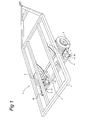
- 1 refers to a vehicle. Only the chassis 2 of this vehicle is shown.
- the upper structure can provide a loading platform, caravan or the like.
- the wheels have reference number 3.
- a manoeuvring device 4 engages both on the left hand and the right hand wheel 3. Details are clear from fig. 2 and 3.
- the manoeuvring device 4 comprises a frame structure, which is common for both manoeuvring devices 4 and has reference number 5. This is fixed in any way to the chassis 2 of the vehicle. It will be understood that if the manoeuvring device is provided by the producer of the vehicle, certain parts of the frame structure can be omitted or included in the chassis.
- a support 6 is pivotally connected with the frame structure 5.
- the pivot point has reference 9.
- a roller 7 is provided rotatable around axis 24. This is driven by an electric motor 21. By pressing the roller 7 against the related wheel, by rotation of the motor and so the rotation of the roller the related vehicle can be manoeuvred. Displacement of the support 6 and in that way the roller 7 is effected with an end plate 8 mounted on the free extremity of the support.
- This plate can be removable for easy changing of the roller or can be permanently mounted to the support, so that the replacement of the roller is more complicated.
- Plate 8 is provided with a pivot 11 on which also a lever 10 engages.
- the other side of the lever 10 is provided with a nut-like portion 12, which can also articulate within pivot 10.
- a further pivot 17 is provided on which an arm engages, being pivotally connected to support 19, being part of the frame structure through pivot 18.
- Screwrod 13 is substantially parallel to axis 24.
- Screw rod 13 is provided at both extremities of screw head 20 (for example hexagonal). By rotation of the screw head 20 on both sides, the screw rod is rotated over the full length thereof. By its accommodation between supports 19 movement in longitudinal direction thereof is not possible.
- This operation can for example be effected by an accumulator-drilling machine having a suitable bit.
- Locking devices (not shown) can be provided ,which lock in one of the end positions of the support shown in fig. 2 and 3, the support relative to the frame structure 5, such that no undesired displacement of the support during driving of the vehicle can occur.
- connection between the screw thread portions 13 and 14 is only realised for transmitting of rotation. At exerting pressure with the rollers 7 against the wheel there is a pulling force between the nut 12 and the pivot 18 as shown in fig. 2 and 3.
- the manoeuvring device is generally referred to by 24.
- the driven wheels are shown by 23.
- Supports 26 are present provided with rollers 27. These supports 26 are pivotable around pivots 29.
- the supports 26 are each provided with a structure corresponding to fig. 1-3, this structure comprises a two-side rod portions 33 and 34. These rod portions are rotatably driven by a central electromotor. Rotation can be in the same direction. In that case screw threads 33 and 34 have opposite hand. Displacement in opposite direction is possible wherein the screw thread 33 and 34 can be identical. Screw thread portions 33 and 34 support two brackets 29 (only one shown) being part of the frame structure 25.
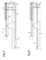
- FIG. 5 a further embodiment is shown.
- the manoeuvring devices are referred to by 44.
- Support 46 is pivotally connected in the way shown in fig. 1 and provided with rollers 47.
- a pivoting tilting plate 51 movement of the lever 50 is converted to movement of the rod 54, 55 respectively.
- a ram 48 In the center is a ram 48, which can move the rods 54, 55 to each other, away from each other respectively.
- Each other mechanism to move the rods 54, 55 to each other, from each other respectively can be used.
- FIG. 6 A further embodiment having rods moving to each other is shown in fig. 6.
- the frame structure has reference number 69 and is provided with a supports 69. Arms 71 are pivotally connected thereto.
- Levers 70 are mounted to end plate of support 66, which are pivotally connected in the way shown in fig. 1.
- Lever 70 is pivotally connected to arm 71.
- the drive rollers can be moved to/from the wheels with an operating mechanism 68, such as (hydraulic, pneumatic, electric) ram.
Applications Claiming Priority (2)
| Application Number | Priority Date | Filing Date | Title |
|---|---|---|---|
| NL1022672A NL1022672C2 (nl) | 2003-02-13 | 2003-02-13 | Manoeuvreerinrichting voor niet aangedreven wagens. |
| NL1022672 | 2003-02-13 |
Publications (2)
| Publication Number | Publication Date |
|---|---|
| EP1447312A1 true EP1447312A1 (de) | 2004-08-18 |
| EP1447312B1 EP1447312B1 (de) | 2006-05-03 |
Family
ID=32678042
Family Applications (1)
| Application Number | Title | Priority Date | Filing Date |
|---|---|---|---|
| EP04075480A Expired - Lifetime EP1447312B1 (de) | 2003-02-13 | 2004-02-13 | Manövriervorrichtung für nicht angetriebene Fahrzeuge |
Country Status (3)
| Country | Link |
|---|---|
| EP (1) | EP1447312B1 (de) |
| DE (1) | DE602004000769T4 (de) |
| NL (1) | NL1022672C2 (de) |
Cited By (13)
| Publication number | Priority date | Publication date | Assignee | Title |
|---|---|---|---|---|
| DE102004058738A1 (de) * | 2004-12-06 | 2006-06-08 | Truma Gerätetechnik GmbH & Co. KG | Hilfsantrieb für einen Anhänger |
| NL1027925C2 (nl) * | 2004-12-30 | 2006-07-04 | Reich Kg | Hulpaandrijving en voertuig voorzien van een hulpaandrijving. |
| GB2432349A (en) * | 2005-11-22 | 2007-05-23 | Mark Darren Shaw | Remote electric cam actuator for trailer manouevring device |
| EP1826106A1 (de) * | 2006-02-28 | 2007-08-29 | James Richard Yates | Maschinen zum Manövrieren von Anhängern |
| GB2448738A (en) * | 2007-04-26 | 2008-10-29 | James Richard Yates | Drive roller for trailer maneuvering machine |
| DE202009005185U1 (de) | 2009-08-26 | 2011-01-20 | Al-Ko Kober Ag | Hilfsantrieb |
| EP1714859B2 (de) † | 2005-04-18 | 2012-04-18 | Truma Gerätetechnik GmbH & Co. KG | Kompakter Hilfsantrieb für einen Anhänger |
| DE202012006084U1 (de) | 2012-05-29 | 2012-07-12 | Truma Gerätetechnik GmbH & Co. KG | Anhänger-Rangierantrieb mit Schlupfoptimierung |
| DE102012010547A1 (de) * | 2012-05-29 | 2013-12-05 | Truma Gerätetechnik GmbH & Co. KG | Anhänger-Rangierantrieb mit Getriebe mit nicht paralleler Achsanordnung |
| EP2910457A1 (de) * | 2014-02-19 | 2015-08-26 | Truma Gerätetechnik GmbH & Co. KG | Rangierantrieb mit Spritzschutz für Anhänger oder dgl. |
| WO2016004200A3 (en) * | 2014-07-01 | 2016-02-18 | Beiler Aaron Jay | Self-propelled trailer |
| EP3290308A3 (de) * | 2016-08-19 | 2018-07-18 | Reich GmbH Regel- und Sicherheitstechnik | Befestigungs- und abstützvorrichtung und anhänger |
| CN110294045A (zh) * | 2018-03-22 | 2019-10-01 | 杭州嘉迈机械有限公司 | 附接装置及其用途、具有这种附接装置的系统和车辆 |
Families Citing this family (1)
| Publication number | Priority date | Publication date | Assignee | Title |
|---|---|---|---|---|
| RU2718476C1 (ru) * | 2019-08-02 | 2020-04-08 | Денис Владимирович Широков | Вспомогательное маневрирующее устройство |
Citations (4)
| Publication number | Priority date | Publication date | Assignee | Title |
|---|---|---|---|---|
| US3826324A (en) | 1972-10-26 | 1974-07-30 | D Stevens | Trailer mover |
| DE2705318A1 (de) * | 1977-02-09 | 1978-08-10 | Daimler Benz Ag | Campingwagen |
| EP1203713A2 (de) * | 2000-09-04 | 2002-05-08 | Reich KG | Hilfsantrieb für einen Anhänger |
| EP1225090A2 (de) * | 2001-01-19 | 2002-07-24 | Carver plc | Vorrichtung zum Bewegen von Fahrzeugen wie Anhänger und Wohnwagen |
-
2003
- 2003-02-13 NL NL1022672A patent/NL1022672C2/nl not_active IP Right Cessation
-
2004
- 2004-02-13 DE DE602004000769T patent/DE602004000769T4/de not_active Expired - Lifetime
- 2004-02-13 EP EP04075480A patent/EP1447312B1/de not_active Expired - Lifetime
Patent Citations (4)
| Publication number | Priority date | Publication date | Assignee | Title |
|---|---|---|---|---|
| US3826324A (en) | 1972-10-26 | 1974-07-30 | D Stevens | Trailer mover |
| DE2705318A1 (de) * | 1977-02-09 | 1978-08-10 | Daimler Benz Ag | Campingwagen |
| EP1203713A2 (de) * | 2000-09-04 | 2002-05-08 | Reich KG | Hilfsantrieb für einen Anhänger |
| EP1225090A2 (de) * | 2001-01-19 | 2002-07-24 | Carver plc | Vorrichtung zum Bewegen von Fahrzeugen wie Anhänger und Wohnwagen |
Cited By (29)
| Publication number | Priority date | Publication date | Assignee | Title |
|---|---|---|---|---|
| EP1842754A2 (de) | 2004-12-06 | 2007-10-10 | Truma Gerätetechnik GmbH & Co. KG | Hilfsantrieb für einen Anhänger |
| WO2006061177A1 (de) * | 2004-12-06 | 2006-06-15 | Truma Gerätetechnik GmbH & Co. KG | Hilfsantrieb für einen anhäger |
| AU2005313534B2 (en) * | 2004-12-06 | 2010-05-20 | Truma Geratetechnik Gmbh & Co. Kg | Servodrive for a trailer |
| DE102004058738A1 (de) * | 2004-12-06 | 2006-06-08 | Truma Gerätetechnik GmbH & Co. KG | Hilfsantrieb für einen Anhänger |
| EP1925540A3 (de) * | 2004-12-06 | 2008-06-04 | Truma Gerätetechnik GmbH & Co. KG | Hilfsantrieb für einen Anhänger |
| EP1925540A2 (de) | 2004-12-06 | 2008-05-28 | Truma Gerätetechnik GmbH & Co. KG | Hilfsantrieb für einen Anhänger |
| EP1679251A2 (de) * | 2004-12-30 | 2006-07-12 | Reich KG | Hilfsantrieb und mit einem Hilfsantrieb versehenes Fahrzeug |
| EP1679251A3 (de) * | 2004-12-30 | 2006-07-26 | Reich KG | Hilfsantrieb und mit einem Hilfsantrieb versehenes Fahrzeug |
| NL1027925C2 (nl) * | 2004-12-30 | 2006-07-04 | Reich Kg | Hulpaandrijving en voertuig voorzien van een hulpaandrijving. |
| EP1714859B2 (de) † | 2005-04-18 | 2012-04-18 | Truma Gerätetechnik GmbH & Co. KG | Kompakter Hilfsantrieb für einen Anhänger |
| GB2432349B (en) * | 2005-11-22 | 2008-01-09 | Mark Darren Shaw | Remote electric CAM actuator |
| GB2432349A (en) * | 2005-11-22 | 2007-05-23 | Mark Darren Shaw | Remote electric cam actuator for trailer manouevring device |
| EP1826106A1 (de) * | 2006-02-28 | 2007-08-29 | James Richard Yates | Maschinen zum Manövrieren von Anhängern |
| GB2448738A (en) * | 2007-04-26 | 2008-10-29 | James Richard Yates | Drive roller for trailer maneuvering machine |
| EP2289776A2 (de) | 2009-08-26 | 2011-03-02 | AL-KO Kober AG | Hilfsfahrantrieb für einen Anhänger |
| DE202009005185U1 (de) | 2009-08-26 | 2011-01-20 | Al-Ko Kober Ag | Hilfsantrieb |
| DE102012010547B4 (de) * | 2012-05-29 | 2015-09-24 | Truma Gerätetechnik GmbH & Co. KG | Rangierantrieb für einen Anhänger |
| DE202012006084U1 (de) | 2012-05-29 | 2012-07-12 | Truma Gerätetechnik GmbH & Co. KG | Anhänger-Rangierantrieb mit Schlupfoptimierung |
| EP2669154A2 (de) | 2012-05-29 | 2013-12-04 | Truma Gerätetechnik GmbH & Co. KG | Anhänger-Rangierantrieb |
| DE102012010547A1 (de) * | 2012-05-29 | 2013-12-05 | Truma Gerätetechnik GmbH & Co. KG | Anhänger-Rangierantrieb mit Getriebe mit nicht paralleler Achsanordnung |
| DE102012010543A1 (de) | 2012-05-29 | 2013-12-05 | Truma Gerätetechnik GmbH & Co. KG | Anhänger-Rangierantrieb mit Schlupfoptimierung |
| EP2669154A3 (de) * | 2012-05-29 | 2014-10-01 | Truma Gerätetechnik GmbH & Co. KG | Anhänger-Rangierantrieb |
| EP2910457A1 (de) * | 2014-02-19 | 2015-08-26 | Truma Gerätetechnik GmbH & Co. KG | Rangierantrieb mit Spritzschutz für Anhänger oder dgl. |
| WO2016004200A3 (en) * | 2014-07-01 | 2016-02-18 | Beiler Aaron Jay | Self-propelled trailer |
| US10300970B2 (en) | 2014-07-01 | 2019-05-28 | New Heights Llc | Self-propelled trailer |
| US11130534B2 (en) | 2014-07-01 | 2021-09-28 | New Heights, Llc | Self-propelled trailer |
| EP3290308A3 (de) * | 2016-08-19 | 2018-07-18 | Reich GmbH Regel- und Sicherheitstechnik | Befestigungs- und abstützvorrichtung und anhänger |
| EP3795460A1 (de) * | 2016-08-19 | 2021-03-24 | Reich GmbH Regel- und Sicherheitstechnik | Befestigungs- und abstützvorrichtung und anhänger |
| CN110294045A (zh) * | 2018-03-22 | 2019-10-01 | 杭州嘉迈机械有限公司 | 附接装置及其用途、具有这种附接装置的系统和车辆 |
Also Published As
| Publication number | Publication date |
|---|---|
| DE602004000769D1 (de) | 2006-06-08 |
| DE602004000769T4 (de) | 2007-10-31 |
| EP1447312B1 (de) | 2006-05-03 |
| NL1022672C2 (nl) | 2004-08-16 |
| DE602004000769T2 (de) | 2007-06-14 |
Similar Documents
| Publication | Publication Date | Title |
|---|---|---|
| EP1447312B1 (de) | Manövriervorrichtung für nicht angetriebene Fahrzeuge | |
| EP1040941B1 (de) | Reifenwechselvorrichtung für Nutzfahrzeuge | |
| EP0482701B1 (de) | Maschine zum Abnehmen von Reifen | |
| US7677582B2 (en) | Vehicular component apparatus | |
| EP1366933B1 (de) | Reifenmontage- und Wulstabdrück-Maschine | |
| US4042139A (en) | Vehicle wheel-removing and handling device | |
| US20040146384A1 (en) | Method and apparatus for moving a vehicle | |
| WO2020176458A1 (en) | Adjustable span tine pallet jack | |
| US7896118B2 (en) | Stretchers | |
| EP2082922B1 (de) | Träger, insbesondere für Fahrräder | |
| CN106739874B (zh) | 车载轮胎拆装机 | |
| EP1584496B1 (de) | Vorrichtung zum Montieren und Demontieren von Rädern | |
| JP4376548B2 (ja) | 産業車両用タイヤ取付け、取外し装置 | |
| CN111016557B (zh) | 用于安装和/或拆卸特别是卡车车轮的车辆车轮的机器 | |
| EP0125551B1 (de) | Tragbarer, gelenkiger Hubwagen zum Erleichtern des Radwechselns von Reisebussen, Lastkraftwagen, Schleppern und ähnlichen Kraftfahrzeugen | |
| WO1994013429A1 (en) | Heat exchanger bundle extractor assembly and method | |
| CN111977564B (zh) | 一种汽车的简易顶升结构及其装置 | |
| WO1996026152A1 (en) | Auto body repair apparatus | |
| JP3606518B2 (ja) | 車両の持上げ移動装置 | |
| WO2011132186A1 (en) | Jack for lifting wheels of motor vehicles to axle height | |
| US4014375A (en) | Thrust-applying mechanism for tire changing apparatus | |
| WO2003002361A1 (en) | Tire changing apparatus and method | |
| CA2314617A1 (en) | Hoist suspended wheel manipulator | |
| CN211869338U (zh) | 移车装置 | |
| EP4067121B1 (de) | Reifenwechselvorrichtung und verfahren zur montage und demontage von reifen |
Legal Events
| Date | Code | Title | Description |
|---|---|---|---|
| PUAI | Public reference made under article 153(3) epc to a published international application that has entered the european phase |
Free format text: ORIGINAL CODE: 0009012 |
|
| AK | Designated contracting states |
Kind code of ref document: A1 Designated state(s): AT BE BG CH CY CZ DE DK EE ES FI FR GB GR HU IE IT LI LU MC NL PT RO SE SI SK TR |
|
| AX | Request for extension of the european patent |
Extension state: AL LT LV MK |
|
| 17P | Request for examination filed |
Effective date: 20041103 |
|
| GRAP | Despatch of communication of intention to grant a patent |
Free format text: ORIGINAL CODE: EPIDOSNIGR1 |
|
| AKX | Designation fees paid |
Designated state(s): DE FR GB IT NL |
|
| GRAS | Grant fee paid |
Free format text: ORIGINAL CODE: EPIDOSNIGR3 |
|
| GRAA | (expected) grant |
Free format text: ORIGINAL CODE: 0009210 |
|
| AK | Designated contracting states |
Kind code of ref document: B1 Designated state(s): DE FR GB IT NL |
|
| PG25 | Lapsed in a contracting state [announced via postgrant information from national office to epo] |
Ref country code: IT Free format text: LAPSE BECAUSE OF FAILURE TO SUBMIT A TRANSLATION OF THE DESCRIPTION OR TO PAY THE FEE WITHIN THE PRESCRIBED TIME-LIMIT;WARNING: LAPSES OF ITALIAN PATENTS WITH EFFECTIVE DATE BEFORE 2007 MAY HAVE OCCURRED AT ANY TIME BEFORE 2007. THE CORRECT EFFECTIVE DATE MAY BE DIFFERENT FROM THE ONE RECORDED. Effective date: 20060503 |
|
| REG | Reference to a national code |
Ref country code: GB Ref legal event code: FG4D |
|
| REF | Corresponds to: |
Ref document number: 602004000769 Country of ref document: DE Date of ref document: 20060608 Kind code of ref document: P |
|
| ET | Fr: translation filed | ||
| PLBE | No opposition filed within time limit |
Free format text: ORIGINAL CODE: 0009261 |
|
| STAA | Information on the status of an ep patent application or granted ep patent |
Free format text: STATUS: NO OPPOSITION FILED WITHIN TIME LIMIT |
|
| 26N | No opposition filed |
Effective date: 20070206 |
|
| PGFP | Annual fee paid to national office [announced via postgrant information from national office to epo] |
Ref country code: IT Payment date: 20080221 Year of fee payment: 5 |
|
| REG | Reference to a national code |
Ref country code: FR Ref legal event code: PLFP Year of fee payment: 12 |
|
| REG | Reference to a national code |
Ref country code: DE Ref legal event code: R082 Ref document number: 602004000769 Country of ref document: DE Representative=s name: HOFSTETTER, SCHURACK & PARTNER PATENT- UND REC, DE |
|
| REG | Reference to a national code |
Ref country code: FR Ref legal event code: PLFP Year of fee payment: 13 |
|
| REG | Reference to a national code |
Ref country code: FR Ref legal event code: PLFP Year of fee payment: 14 |
|
| REG | Reference to a national code |
Ref country code: FR Ref legal event code: PLFP Year of fee payment: 15 |
|
| PGFP | Annual fee paid to national office [announced via postgrant information from national office to epo] |
Ref country code: FR Payment date: 20200220 Year of fee payment: 17 |
|
| PGFP | Annual fee paid to national office [announced via postgrant information from national office to epo] |
Ref country code: NL Payment date: 20210218 Year of fee payment: 18 |
|
| PGFP | Annual fee paid to national office [announced via postgrant information from national office to epo] |
Ref country code: GB Payment date: 20210222 Year of fee payment: 18 Ref country code: DE Payment date: 20210225 Year of fee payment: 18 |
|
| PG25 | Lapsed in a contracting state [announced via postgrant information from national office to epo] |
Ref country code: FR Free format text: LAPSE BECAUSE OF NON-PAYMENT OF DUE FEES Effective date: 20210228 |
|
| REG | Reference to a national code |
Ref country code: DE Ref legal event code: R119 Ref document number: 602004000769 Country of ref document: DE |
|
| REG | Reference to a national code |
Ref country code: NL Ref legal event code: MM Effective date: 20220301 |
|
| GBPC | Gb: european patent ceased through non-payment of renewal fee |
Effective date: 20220213 |
|
| PG25 | Lapsed in a contracting state [announced via postgrant information from national office to epo] |
Ref country code: NL Free format text: LAPSE BECAUSE OF NON-PAYMENT OF DUE FEES Effective date: 20220301 |
|
| PG25 | Lapsed in a contracting state [announced via postgrant information from national office to epo] |
Ref country code: GB Free format text: LAPSE BECAUSE OF NON-PAYMENT OF DUE FEES Effective date: 20220213 Ref country code: DE Free format text: LAPSE BECAUSE OF NON-PAYMENT OF DUE FEES Effective date: 20220901 |