EP1445855A2 - Antriebsanordnung und Verfahren um den Wirkungsgrad zu verbessern - Google Patents
Antriebsanordnung und Verfahren um den Wirkungsgrad zu verbessern Download PDFInfo
- Publication number
- EP1445855A2 EP1445855A2 EP03104302A EP03104302A EP1445855A2 EP 1445855 A2 EP1445855 A2 EP 1445855A2 EP 03104302 A EP03104302 A EP 03104302A EP 03104302 A EP03104302 A EP 03104302A EP 1445855 A2 EP1445855 A2 EP 1445855A2
- Authority
- EP
- European Patent Office
- Prior art keywords
- electric machines
- electric
- arrangement according
- torque
- electric machine
- Prior art date
- Legal status (The legal status is an assumption and is not a legal conclusion. Google has not performed a legal analysis and makes no representation as to the accuracy of the status listed.)
- Granted
Links
Images


Classifications
-
- B—PERFORMING OPERATIONS; TRANSPORTING
- B60—VEHICLES IN GENERAL
- B60L—PROPULSION OF ELECTRICALLY-PROPELLED VEHICLES; SUPPLYING ELECTRIC POWER FOR AUXILIARY EQUIPMENT OF ELECTRICALLY-PROPELLED VEHICLES; ELECTRODYNAMIC BRAKE SYSTEMS FOR VEHICLES IN GENERAL; MAGNETIC SUSPENSION OR LEVITATION FOR VEHICLES; MONITORING OPERATING VARIABLES OF ELECTRICALLY-PROPELLED VEHICLES; ELECTRIC SAFETY DEVICES FOR ELECTRICALLY-PROPELLED VEHICLES
- B60L15/00—Methods, circuits, or devices for controlling the traction-motor speed of electrically-propelled vehicles
- B60L15/32—Control or regulation of multiple-unit electrically-propelled vehicles
- B60L15/38—Control or regulation of multiple-unit electrically-propelled vehicles with automatic control
-
- B—PERFORMING OPERATIONS; TRANSPORTING
- B60—VEHICLES IN GENERAL
- B60L—PROPULSION OF ELECTRICALLY-PROPELLED VEHICLES; SUPPLYING ELECTRIC POWER FOR AUXILIARY EQUIPMENT OF ELECTRICALLY-PROPELLED VEHICLES; ELECTRODYNAMIC BRAKE SYSTEMS FOR VEHICLES IN GENERAL; MAGNETIC SUSPENSION OR LEVITATION FOR VEHICLES; MONITORING OPERATING VARIABLES OF ELECTRICALLY-PROPELLED VEHICLES; ELECTRIC SAFETY DEVICES FOR ELECTRICALLY-PROPELLED VEHICLES
- B60L50/00—Electric propulsion with power supplied within the vehicle
-
- F—MECHANICAL ENGINEERING; LIGHTING; HEATING; WEAPONS; BLASTING
- F16—ENGINEERING ELEMENTS AND UNITS; GENERAL MEASURES FOR PRODUCING AND MAINTAINING EFFECTIVE FUNCTIONING OF MACHINES OR INSTALLATIONS; THERMAL INSULATION IN GENERAL
- F16H—GEARING
- F16H48/00—Differential gearings
- F16H48/06—Differential gearings with gears having orbital motion
- F16H48/08—Differential gearings with gears having orbital motion comprising bevel gears
Definitions
- the invention relates to an arrangement for conversion from electrical to mechanical energy and vice versa, in particular for driving a vehicle and for energy recovery during its deceleration, with the features of claim 1 and a Method for operating such an arrangement with the features of claim 20.
- Electric machines as a drive and / or for energy have basically at least one electric machine.
- These Electric machine can, for example, as a prime mover be used electric motor.
- One as a vehicle drive inserted electric motor can either directly or connected via a gear with an output be.
- the efficiency of electrical machines is depending on the design of the torque output as well as the current speed. There especially for vehicle drives very different Torque and speed requirements occur, depending on the current operating state the electric machine operating points with different degrees of efficiency.
- a located between electric machine and output Transmission can be used as a speed converter and allows an improvement in the overall efficiency.
- the maximum speeds of the electric motor in this case usually limit the achievable maximum speeds of the vehicle.
- Typical installed power for drives for Road vehicles range from about 3 kW to about 70 kW. Pure electric vehicles need energy storage Accumulators. With a charge of this Batteries are typical ranges of about 20 to 200 km possible. Larger ranges are usually through limited the necessary accumulator weight. These compared with conventional drives Internal combustion engines insufficient ranges and which is relatively due to the large batteries high vehicle weights have so far been a nationwide Prevention of the spread of electric vehicles.
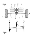
- FIG. 10a shows a simplified principle of a conventional electric drive with only one electric machine.
- An engine output shaft 12 of the electric machine E drives via a differential gear 14 two drive shafts 16, which are used to drive wheels 18 of a vehicle (not shown) are used.
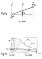
- FIG. 10 b illustrates typical relationships between a motor torque M, a vehicle speed v and a drive efficiency ⁇ in an operating map.
- the driving speed here is directly proportional to the engine speed n, since the electric machine E is coupled to the vehicle wheels 18 without an intermediate speed converter.
- the electric machine E can deliver a peak power P max of approximately 75 kW and a continuous power P const of approximately 30 kW.
- P max peak power
- P const of approximately 30 kW.
- the output torque decreases with increasing speed.
- the maximum torque is available at low speeds, so that the machine can deliver a high starting torque.
- a standardized driving cycle NEDC simulates an average operation of a vehicle and is shown as a bounded area in the diagram. In this driving cycle, the electric drive operates in an efficiency range of only about 65% on average.
- An inventive arrangement for the conversion of electrical to mechanical energy and vice versa includes at least two electric machines, over an intermediate gear are coupled together.
- the electric machines are by means of a control device depending on a speed request and / or a torque request to a Output shaft of the intermediate gear variably controllable.
- the arrangement according to the invention is suitable in particular for driving a vehicle and / or for energy recovery during its deceleration.
- By the coupling of at least two electric machines via an intermediate gear can at least one of the electric machines in a favorable efficiency range be operated while the other Electric machine is either switched off, with lower power in a less favorable efficiency range or with equal power in low efficiency range can be operated can.
- a conventional drive arrangement with only one electric machine in a partial load operation operated in an unfavorable efficiency range must be with the inventive Arrangement a part-load operation with a smaller one Machine allows while the other, variable switchable electric machine switched off remains.
- the respective switchable electric machine can optionally via a freewheel device with the intermediate gear be coupled, so that a drive torque the respectively switched on machine over supported in one direction blocking freewheel can be. Possibly. can the freewheel device unlockable and / or in their reverse direction be switchable, so that also a generator operation allows with only one electric machine in the same way is.
- An advantageous embodiment may be in use consist of different electrical machines.
- one of the electric machines can be a synchronous machine be that at low speeds has a very good efficiency.
- an asynchronous machine as another electric machine can be a good at higher speeds Efficiency can be achieved. That way you can through a suitable tax or regulatory strategy the advantages of both machine types are combined. For example. can be a part load range with lower ones Speeds and sometimes high torque requirements with a high efficiency with the Synchronous machine are covered. For higher performance requirements at higher speed ranges then the asynchronous machine can be variably added become. This then serves as support the synchronous machine.
- An advantageous variant can be combined a controlled and thus inexpensive electric machine with a regulated electric machine consist. This can then, for example, an asynchronous machine be. This way can be a cheap one Combination of a controlled machine with a controlled machine can be realized.
- the fine adjustment the desired speed can preferably with the regulated machine can be achieved.
- differential gear As an intermediate gear is particularly suitable known differential gear, as it is, for example. In Vehicle construction is used. A differential gear is particularly suitable for a symmetrical Construction with two similar electric machines. Likewise, however, can also be a planetary gear be used as an intermediate gear, which is in particular for an asymmetrical structure with different dimensioned electrical machines suitable. By using two identical differential gears as coupling gear for the electric machines and as axle differential gear to the drive The vehicle wheels may be the cost a use of two different gears be reduced.
- a relatively low torque requirement is preferably only one of the electrical machines in operation.
- Their drive torque is based on the freewheel device, between the other Electric machine and the intermediate gear arranged is and allows only one direction of rotation.
- the in operation electric machine can in one low efficiency range can be operated.
- This is an advantage over an arrangement with only one electric machine, which is the total power would have to cover. This would be at this Example of operation at low power and thus operated at much worse efficiency Need to become.
- a part-load operation with a low torque requirement and a higher speed requirement can be covered with only one electric machine for so long until they are at their speed limit becomes. If exceeded, can be variable the second electric machine added and at first with even less power operate. Again, the resulting Overall efficiency very favorable, since the efficiency the electric machine with the higher power output in the calculation of the overall efficiency clearly dominated. This electric machine will be in operated a favorable efficiency range while the part load running, added Machine easily in a less favorable efficiency range can run. By an increase the power output of the added machine this increasingly gets into more favorable efficiency ranges, so that here again both electric machines near their optimal operating point can be operated.
- a recuperation operation is characterized in that that the electric machines operated as generators become.
- This braking energy is converted into electrical Energy converted, stored in accumulators can be.
- In a typical initial case at low speeds becomes one the electric machines in generator mode over the Driven intermediate gear.
- the from the braking energy Energy gained through the resulting Imbalance of torques initially for acceleration the second machine to be used to this in an operating point with favorable efficiency bring to.
- the condition by switching on a moment in this electric machine be stabilized.
- Both electric machines then run in symmetrical operation as a generator and recuperate each one approximately same performance.
- the transition to the symmetrical Operating status can optionally also be continuous done to the comfort requirements in the To meet motor vehicle.
- a reverse drive is due to its subordinate Share in the overall operation with regard to its efficiency unproblematic. Normally Here is just one of the electric machines in Business. The direction of rotation is only reversed. The freewheel device described above in this case is not able to support the torque of the driven machine too enable. The non-driven machine However, it can actively stabilize this Operating point can be used. Alternatively, you can a switchable in its reverse direction freewheel support the moment.
- Figure 1a shows the basic principle of a drive assembly according to the invention with at least two electric machines E 1 and E 2 , which are coupled via an intermediate gear 20 with a differential gear 14.
- the intermediate gear 20 has an output shaft 21 for driving the differential gear 14.
- the differential gear 14 is coupled to two drive shafts 16 which serve to drive wheels 18 of a vehicle (not shown).
- At least one of the two electric machines E 1 and E 2 has a freewheel device 22, which can optionally be unlocked and / or reversible in its reverse direction.
- a differential gear 20 is particularly suitable for a differential gear, which may possibly be identical to the differential gear 14 for driving the wheels 18.
- the intermediate gear 20 may alternatively be a planetary gear o. The like., So that motors of the same or different size and power can be easily coupled together.
- the drive arrangement according to the invention is suitable both for driving and for generating energy.
- the electric machines operate in a generator mode (see Figures 7 and 8).
- the two electric machines E 1 and E 2 are preferably each coupled to a power supply and / or energy storage system (not shown), which serves to supply the electrical drive energy and / or storage of electrical energy as soon as the electric machines run in a recuperation and as Generators are operated.
- energy storage are, for example, known per se accumulators.
- a power supply system in particular, a fuel cell system is also suitable.
- FIG. 1b illustrates the functional relationships of the drive arrangement according to FIG. 1a.
- Both electric machines E 1 and E 2 can each be operated at different speeds n 1 and n 2 .
- the output power P A is in each case a product of the output torque M A and the output rotational speed n A , so that the following applies: ie, the output power P A corresponds to a sum of the individual powers P 1 and P 2 of the coupled electric machines E 1 and E 2 .
- the inventive arrangement with two variably controllable electric machines E 1 and E 2 , which are coupled together via an intermediate gear 20, in particular a differential gear, allows an efficiency optimization of the drive, since the electric machines can work in favorable operating points.
- the disadvantage of additional losses due to the mechanical friction in the intermediate gear 20 is more than offset by the achievable efficiency improvements.
- a synchronous machine has significantly better efficiencies in low speed ranges than an asynchronous machine in comparable operating ranges.
- the part-speed range at low speeds can be covered in this way by preferred use of the synchronous machine, while for higher powers and speeds the asynchronous machine can be added supportive.
- a very cost-effective variant can, for example, consist in the use of a controlled synchronous machine and a controlled asynchronous machine.
- the following exemplary embodiments show different operating modes of the coupled electrical machines E 1 and E 2 .
- E 1 and E 2 For the sake of simplicity, it is assumed in the following that two similar electric machines of the same size and power are used, which thus each have the same characteristics. However, even better efficiencies can be achieved with optimized tuning of two different electric machines.
- the torque M 2 of the second electric machine E 2 is supported via the intermediate gear 20 on the freewheel 22, which is arranged between the first electric machine E 1 and the intermediate gear 20 (see FIG.
- the freewheel 22 thus prevents reverse rotation of the first electric machine E 1 .
- the freewheel 22 for torque support in turn prevents the reverse rotation of the first electric machine E first
- M max M max .
- the freewheel 22 for torque support in turn prevents the reverse rotation of the first electric machine E first
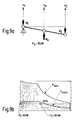
- FIGS. 7 and 8 illustrate a generator operation the drive assembly, in the example.
- a Braking energy required to brake the vehicle be used to drive the electrical machines can. These can during this so-called.
- Recuperation operation the generated electrical energy for intermediate storage on accumulators (not shown), so that the overall efficiency the drive improved and as little as possible Braking energy in a conventional service brake is converted into frictional heat.
- FIGS. 7a and 7b show, as a starting situation, a partial load drop (M A ⁇ -500 Nm) at low speed (v ⁇ 50 km / h).
- the resulting torque imbalance is used by the resulting torque imbalance to accelerate the first electric machine E 1 in order to bring it into an area with favorable efficiency.
- the state is stabilized by switching on a torque -M 1 of the first electric machine E 1 .
- This symmetrical operation is illustrated with reference to FIGS. 8a and 8b.
- the connection of a braking torque can be carried out continuously in order not to produce a torque jump, which is undesirable for reasons of comfort.
- a conventional freewheel By reversing the direction of travel, a conventional freewheel can not support this mode.
- the reverse operation can, for example, be achieved in that the first electric machine E 1 actively stabilizes the operating point of the second electric machine E 2 .
- the resulting unfavorable drive efficiency is not relevant for the overall efficiency of the drive due to the relatively rarely required reverse operation.
Abstract
Description
- Figur 1
- ein Prinzipschaltbild einer erfindungsgemäßen Antriebsanordnung,
- Figuren 2 bis 9
- verschiedene Betriebsmodi und zugehörige Kennfelder der erfindungsgemäßen Antriebsanordnung,
- Figur 10a
- eine herkömmliche Antriebsanordnung und
- Figur 10b
- ein beispielhaftes Betriebskennfeld der Antriebsanordnung entsprechend Figur 10a.

Claims (33)
- Anordnung zur Wandlung von elektrischer in mechanische Energie und umgekehrt, insbesondere zum Antrieb eines Fahrzeugs und/oder zur Energierückgewinnung bei dessen Abbremsung, mit wenigstens zwei Elektromaschinen (E1, E2), die über ein, mit einer Abtriebswelle (21) gekoppeltes Zwischengetriebe (20) miteinander gekoppelt sind, und mit einer Steuerungseinrichtung zur variablen Steuerung der Elektromaschinen (E1, E2) in Abhängigkeit einer Drehzahlanforderung (nA) und/oder einer Drehmomentanforderung (MA) an der Abtriebswelle (21).
- Anordnung nach Anspruch 1, dadurch gekennzeichnet, dass zwischen wenigstens einer der Elektromaschinen (E1, E2) und dem Zwischengetriebe (20) eine Freilaufeinrichtung (22) vorgesehen ist.
- Anordnung nach Anspruch 2, dadurch gekennzeichnet, dass die Freilaufeinrichtung (22) entsperrbar und/oder in ihrer Sperrrichtung umschaltbar ist.
- Anordnung nach einem der Ansprüche 1 bis 3, dadurch gekennzeichnet, dass die Anordnung zwei Elektromaschinen (E1, E2) ungefähr gleicher Leistung aufweist.
- Anordnung nach einem der Ansprüche 1 bis 3, dadurch gekennzeichnet, dass zumindest eine der Elektromaschinen (E1) eine Synchronmaschine ist, und dass zumindest eine weitere Elektromaschine (E2) eine Asynchronmaschine ist.
- Anordnung nach Anspruch 5, dadurch gekennzeichnet, dass die Synchronmaschine variabel steuerbar und/oder regelbar ist.
- Anordnung nach Anspruch 5 oder 6, dadurch gekennzeichnet, dass die Asynchronmaschine variabel steuerbar und/oder regelbar ist.
- Anordnung nach einem der Ansprüche 1 bis 7, dadurch gekennzeichnet, dass das Zwischengetriebe (20) ein Differenzialgetriebe ist.
- Anordnung nach einem der Ansprüche 1 bis 7, dadurch gekennzeichnet, dass das Zwischengetriebe (20) ein Planetengetriebe ist.
- Anordnung nach einem der Ansprüche 1 bis 9, dadurch gekennzeichnet, dass bei einem Teillastbetrieb mit einer niedrigen Drehzahl- (nA) und Drehmomentanforderung (MA) eine der Elektromaschinen (E2) antreibbar ist, während die nicht angetriebene Elektromaschine (E1) mittels der Freilaufeinrichtung (22) blockierbar ist.
- Anordnung nach einem der Ansprüche 1 bis 10, dadurch gekennzeichnet, dass bei einem Teillastbetrieb mit einer niedrigen Drehmomentanforderung (MA) und einer höheren Drehzahlanforderung (nA) beide Elektromaschinen (E1, E2) angetreibbar sind, wobei die mit niederer Drehzahl (n1) betriebene Elektromaschine (E1) eine Momentenabstützung mittels der Freilaufeinrichtung (22) gegen das von der jeweils anderen Elektromaschine (E2) gelieferte Drehmoment (M2) erfährt, wenn die Drehzahl der Elektromaschine (E1) kleiner Null würde.
- Anordnung nach einem der Ansprüche 1 bis 11, dadurch gekennzeichnet, dass bei einem Volllastbetrieb mit einer hohen Drehmomentanforderung (MA) und einer niedrigen Drehzahlanforderung (nA) eine der Elektromaschinen (E2) angetreibbar ist, während die nicht angetriebene Elektromaschine (E1) mittels einer Freilaufeinrichtung (22) blockiert ist.
- Anordnung nach einem der Ansprüche 1 bis 12, dadurch gekennzeichnet, dass bei einem Rekuperationsbetrieb zumindest eine der Elektromaschinen (E1, E2) als Generator betreibbar ist.
- Anordnung nach Anspruch 13, dadurch gekennzeichnet, dass bei einer negativen Momentenanforderung (-MA) an der Abtriebswelle (21) eine der Elektromaschinen (E2) als Generator betreibbar ist.
- Anordnung nach Anspruch 13 oder 14, dadurch gekennzeichnet, dass bei einer negativen Momentenanforderung (-MA) an der Abtriebswelle (21) beide Elektromaschinen (E1, E2) als Generator betreibbar sind.
- Anordnung nach einem der Ansprüche 13 bis 15, dadurch gekennzeichnet, dass bei einer negativen Momentenanforderung (-MA) an der Abtriebswelle (21) zunächst nur eine der Elektromaschinen (E2) als Generator betreibbar ist, und dass nach der Beschleunigung der anderen Elektromaschine (E1) auf eine Betriebsdrehzahl (n1) diese als Generator hinzu schaltbar ist.
- Anordnung nach einem der Ansprüche 1 bis 16, dadurch gekennzeichnet, dass zumindest eine der Elektromaschinen (E1, E2) in ihrer Drehrichtung umkehrbar ist.
- Anordnung nach einem der Ansprüche 1 bis 17, dadurch gekennzeichnet, dass bei einer Umkehrung der Drehrichtung einer der Elektromaschinen (E2) die jeweils andere Elektromaschine (E1) zur Momentenabstützung als Generator betreibbar ist.
- Anordnung nach einem der Ansprüche 1 bis 18, dadurch gekennzeichnet, dass die Freilaufeinrichtung (22) zur Momentenabstützung bei einer Drehrichtungsumkehr einer der Elektromaschinen (E2) in ihrer Sperrrichtung umschaltbar ist.
- Verfahren zur Wandlung von elektrischer in mechanische Energie und umgekehrt, insbesondere zum Antrieb eines Fahrzeugs und/oder zur Energierückgewinnung bei dessen Abbremsung, bei dem wenigstens zwei, über ein Zwischengetriebe (20) miteinander gekoppelte Elektromaschinen (E1, E2) eine Abtriebswelle (21) antreiben bzw. von dieser angetrieben werden, wobei die Elektromaschinen (E1, E2) in Abhängigkeit einer Drehzahl- (nA) und/oder Drehmomentanforderung (MA) an der Abtriebswelle (21) variabel gesteuert und/oder geregelt werden.
- Verfahren nach Anspruch 20, dadurch gekennzeichnet, dass eine Ausgangsdrehzahl (nA) der Abtriebswelle (21) einem Durchschnitt der einzelnen Drehzahlen (n1, n2) der Elektromaschinen (E1, E2) entspricht.
- Verfahren nach Anspruch 20 oder 21, dadurch gekennzeichnet, dass ein Ausgangsdrehmoment (MA) an der Abtriebswelle (21) einer Summe der von den Elektromaschinen (E1, E2) gelieferten einzelnen Drehmomente (M1, M2) entspricht.
- Verfahren nach einem der Ansprüche 20 bis 22, dadurch gekennzeichnet, dass eine Ausgangsleistung (PA) an der Abtriebswelle (21) einer Summe der von den Elektromaschinen (E1, E2) gelieferten einzelnen Leistungen (P1, P2) entspricht.
- Verfahren nach einem der Ansprüche 20 bis 23, dadurch gekennzeichnet, dass bei einem Teillastbetrieb mit einer niedrigen Drehzahl- (nA) und Drehmomentanforderung (MA) nur eine der Elektromaschinen (E2) angetrieben wird, während die nicht angetriebene Elektromaschine (E1) mittels einer Freilaufeinrichtung (22) blockiert wird.
- Verfahren nach einem der Ansprüche 20 bis 24, dadurch gekennzeichnet, dass bei einem Teillastbetrieb mit einer niedrigen Drehmomentanforderung (MA) und einer höheren Drehzahlanforderung (nA) beide Elektromaschinen (E1, E2) angetrieben werden, wobei die mit niederer Drehzahl (n1) betriebene Elektromaschine (E1) eine Momentenabstützung mittels der Freilaufeinrichtung (22) gegen das von der jeweils anderen Elektromaschine (E2) gelieferte Drehmoment (M2) erfahren kann.
- Verfahren nach einem der Ansprüche 20 bis 25, dadurch gekennzeichnet, dass bei einem Volllastbetrieb mit einer hohen Drehmomentanforderung (MA) und einer niedrigen Drehzahlanforderung (nA) nur eine der Elektromaschinen (E2) angetrieben wird, während die nicht angetriebene Elektromaschine (E1) mittels einer Freilaufeinrichtung (22) blockiert wird.
- Verfahren nach einem der Ansprüche 20 bis 26, dadurch gekennzeichnet, dass bei einem Rekuperationsbetrieb zumindest eine der Elektromaschinen (E1, E2) als Generator betrieben wird.
- Verfahren nach Anspruch 27, dadurch gekennzeichnet, dass bei einer negativen Momentenanforderung (-MA) an der Abtriebswelle (21) nur eine der Elektromaschinen (E2) als Generator betrieben wird.
- Verfahren nach Anspruch 27 oder 28, dadurch gekennzeichnet, dass bei einer negativen Momentenanforderung (-MA) an der Abtriebswelle (21) beide Elektromaschinen (E1, E2) als Generator betrieben werden.
- Verfahren nach einem der Ansprüche 27 bis 29, dadurch gekennzeichnet, dass bei einer negativen Momentenanforderung (-MA) an der Abtriebswelle (21) zunächst nur eine der Elektromaschinen (E2) als Generator betrieben wird, und dass nach der Beschleunigung der anderen Elektromaschine (E1) auf eine Betriebsdrehzahl (n1) diese als Generator hinzu geschaltet wird.
- Verfahren nach einem der Ansprüche 20 bis 30, dadurch gekennzeichnet, dass zumindest eine der Elektromaschinen (E1, E2) in ihrer Drehrichtung umkehrbar ist.
- Verfahren nach einem der Ansprüche 20 bis 31, dadurch gekennzeichnet, dass bei einer Umkehrung der Drehrichtung einer der Elektromaschinen (E2) die jeweils andere Elektromaschine (E1) zur Momentenabstützung als Generator betrieben wird.
- Verfahren nach einem der Ansprüche 20 bis 31, dadurch gekennzeichnet, dass die Freilaufeinrichtung (22) zur Momentenabstützung bei einer Drehrichtungsumkehr einer der Elektromaschinen (E2) in ihrer Sperrrichtung umgeschaltet wird.
Applications Claiming Priority (2)
| Application Number | Priority Date | Filing Date | Title |
|---|---|---|---|
| DE10304610 | 2003-02-05 | ||
| DE10304610A DE10304610A1 (de) | 2003-02-05 | 2003-02-05 | Anordnung und Verfahren zur Wandlung von mechanischer in elektrische Energie und umgekehrt |
Publications (3)
| Publication Number | Publication Date |
|---|---|
| EP1445855A2 true EP1445855A2 (de) | 2004-08-11 |
| EP1445855A3 EP1445855A3 (de) | 2006-02-08 |
| EP1445855B1 EP1445855B1 (de) | 2012-01-11 |
Family
ID=32603155
Family Applications (1)
| Application Number | Title | Priority Date | Filing Date |
|---|---|---|---|
| EP03104302A Expired - Lifetime EP1445855B1 (de) | 2003-02-05 | 2003-11-21 | Antriebsanordnung und Verfahren um den Wirkungsgrad zu verbessern |
Country Status (3)
| Country | Link |
|---|---|
| EP (1) | EP1445855B1 (de) |
| JP (1) | JP2004242498A (de) |
| DE (1) | DE10304610A1 (de) |
Cited By (7)
| Publication number | Priority date | Publication date | Assignee | Title |
|---|---|---|---|---|
| CN104802661A (zh) * | 2014-01-27 | 2015-07-29 | 吴伟 | 双机双控双开电动三轮车的控制连接线路 |
| EP3079240A1 (de) * | 2015-03-16 | 2016-10-12 | Thunder Power Hong Kong Ltd. | Verfahren zur steuerung von betriebsdrehzahl und -drehmoment eines elektromotors |
| CN106163861A (zh) * | 2014-04-03 | 2016-11-23 | 雅马哈发动机工程株式会社 | 电动系统和具有其的运输设备 |
| FR3080069A1 (fr) * | 2018-04-17 | 2019-10-18 | Valeo Equipements Electriques Moteur | Chaine de traction optimisee de vehicule automobile comprenant deux machines electriques tournantes |
| EP3659426A1 (de) * | 2018-11-29 | 2020-06-03 | Deere & Company | Fahrzeug antriebsstrang anordnung |
| FR3115736A1 (fr) | 2020-11-02 | 2022-05-06 | Renault S.A.S | Groupe motopropulseur pour véhicule automobile à propulsion ou traction électrique et procédé de commande associé |
| CN115467944A (zh) * | 2022-09-27 | 2022-12-13 | 奇瑞汽车股份有限公司 | 动力耦合系统和车辆 |
Families Citing this family (7)
| Publication number | Priority date | Publication date | Assignee | Title |
|---|---|---|---|---|
| CN100421979C (zh) * | 2007-02-02 | 2008-10-01 | 吉林大学 | 混合动力汽车用的动力耦合装置 |
| DE102008046606B4 (de) * | 2008-08-06 | 2011-04-21 | Adensis Gmbh | Photovoltaikanlage |
| DE102010022749B4 (de) * | 2009-06-25 | 2017-01-12 | Schaeffler Technologies AG & Co. KG | Verfahren zum Steuern eines Kraftfahrzeugs mit Doppelkupplungsgetriebe |
| DE102012110269A1 (de) * | 2012-10-26 | 2014-04-30 | Dr. Ing. H.C. F. Porsche Aktiengesellschaft | Antriebsstrang eines rein elektrisch antreibbaren Kraftfahrzeugs |
| DE102014010336A1 (de) * | 2014-07-10 | 2016-01-28 | Juan Carlos González Villar | Antriebssystem für Förder-, Extruder-, Schub -, Zugeinrichtungen, Gleichlaufanwendungen |
| JP6611128B2 (ja) * | 2016-01-07 | 2019-11-27 | 住友重機械工業株式会社 | 搬送台車 |
| DE102020204326A1 (de) | 2020-04-02 | 2021-10-07 | Adaptive Balancing Power GmbH | Doppelmotoreinheit für einen Schwungmassenspeicher mit nichtlinearer Ge-samt-Leistungskennlinie |
Citations (6)
| Publication number | Priority date | Publication date | Assignee | Title |
|---|---|---|---|---|
| WO1993005567A1 (en) * | 1991-08-29 | 1993-03-18 | Strohm Bryan W | Computer controlled vehicle drive system |
| US5365153A (en) * | 1992-06-10 | 1994-11-15 | Fuji Electric Co., Ltd. | AC variable speed driving apparatus and electric vehicle using the same |
| EP0838359A2 (de) * | 1996-05-20 | 1998-04-29 | Toyota Jidosha Kabushiki Kaisha | Antriebsvorrichtung und Verfahren zur Steuerung desselben |
| US6248036B1 (en) * | 1998-02-19 | 2001-06-19 | Hitachi, Ltd. | Transmission and vehicle and bicycle using the same |
| US20010049570A1 (en) * | 2000-05-25 | 2001-12-06 | Aisin Aw Co., Ltd. | Control apparatus and control method for hybrid vehicle |
| US6416437B2 (en) * | 1999-12-28 | 2002-07-09 | Hyundai Motor Company | Transmission for hybrid electric vehicle |
Family Cites Families (8)
| Publication number | Priority date | Publication date | Assignee | Title |
|---|---|---|---|---|
| US4354144A (en) * | 1981-07-24 | 1982-10-12 | Mccarthy Milton E H | Transmissionless drive system |
| JPH06153325A (ja) * | 1992-10-28 | 1994-05-31 | Nissan Motor Co Ltd | 電気自動車用動力制御装置 |
| JPH06284788A (ja) * | 1993-03-25 | 1994-10-07 | Toyota Motor Corp | モータ制御装置 |
| EP0708896B1 (de) * | 1993-07-19 | 1997-07-16 | Satellite Gear System Ltd. | Stufenlos verstellbares formschlüssiges satellitengetriebe |
| JPH08163714A (ja) * | 1994-12-06 | 1996-06-21 | Mitsubishi Motors Corp | 電気自動車 |
| JP2001287556A (ja) * | 2000-04-06 | 2001-10-16 | Toyota Motor Corp | 動力伝達装置 |
| JP2002036894A (ja) * | 2000-07-31 | 2002-02-06 | Mitsubishi Motors Corp | モータ駆動車両の動力伝達装置 |
| JP3731456B2 (ja) * | 2000-08-03 | 2006-01-05 | トヨタ自動車株式会社 | 変速機 |
-
2003
- 2003-02-05 DE DE10304610A patent/DE10304610A1/de not_active Withdrawn
- 2003-11-21 EP EP03104302A patent/EP1445855B1/de not_active Expired - Lifetime
-
2004
- 2004-02-04 JP JP2004028586A patent/JP2004242498A/ja active Pending
Patent Citations (6)
| Publication number | Priority date | Publication date | Assignee | Title |
|---|---|---|---|---|
| WO1993005567A1 (en) * | 1991-08-29 | 1993-03-18 | Strohm Bryan W | Computer controlled vehicle drive system |
| US5365153A (en) * | 1992-06-10 | 1994-11-15 | Fuji Electric Co., Ltd. | AC variable speed driving apparatus and electric vehicle using the same |
| EP0838359A2 (de) * | 1996-05-20 | 1998-04-29 | Toyota Jidosha Kabushiki Kaisha | Antriebsvorrichtung und Verfahren zur Steuerung desselben |
| US6248036B1 (en) * | 1998-02-19 | 2001-06-19 | Hitachi, Ltd. | Transmission and vehicle and bicycle using the same |
| US6416437B2 (en) * | 1999-12-28 | 2002-07-09 | Hyundai Motor Company | Transmission for hybrid electric vehicle |
| US20010049570A1 (en) * | 2000-05-25 | 2001-12-06 | Aisin Aw Co., Ltd. | Control apparatus and control method for hybrid vehicle |
Cited By (15)
| Publication number | Priority date | Publication date | Assignee | Title |
|---|---|---|---|---|
| CN104802661A (zh) * | 2014-01-27 | 2015-07-29 | 吴伟 | 双机双控双开电动三轮车的控制连接线路 |
| EP3127739A4 (de) * | 2014-04-03 | 2018-02-14 | Yamaha Motor Engineering Co., Ltd. | Elektrisches system und damit ausgestattete transportvorrichtung |
| CN106163861B (zh) * | 2014-04-03 | 2019-07-16 | 雅马哈发动机工程株式会社 | 电动系统和具有其的运输设备 |
| CN106163861A (zh) * | 2014-04-03 | 2016-11-23 | 雅马哈发动机工程株式会社 | 电动系统和具有其的运输设备 |
| US9866163B2 (en) | 2015-03-16 | 2018-01-09 | Thunder Power New Energy Vehicle Development Company Limited | Method for controlling operating speed and torque of electric motor |
| US9941829B2 (en) | 2015-03-16 | 2018-04-10 | Thunder Power New Energy Vehicle Development Company Limited | Method for controlling operating speed and torque of electric motor |
| US9973126B2 (en) | 2015-03-16 | 2018-05-15 | Thunder Power New Energy Vehicle Development Company Limited | Method for controlling operating speed and torque of electric motor |
| US10320319B2 (en) | 2015-03-16 | 2019-06-11 | Thunder Power New Energy Vehicle Development Company Limited | Method for controlling operating speed and torque of electric motor |
| US10333450B2 (en) | 2015-03-16 | 2019-06-25 | Thunder Power New Energy Vehicle Development Company Limited | Method for controlling operating speed and torque of electric motor |
| EP3079240A1 (de) * | 2015-03-16 | 2016-10-12 | Thunder Power Hong Kong Ltd. | Verfahren zur steuerung von betriebsdrehzahl und -drehmoment eines elektromotors |
| FR3080069A1 (fr) * | 2018-04-17 | 2019-10-18 | Valeo Equipements Electriques Moteur | Chaine de traction optimisee de vehicule automobile comprenant deux machines electriques tournantes |
| EP3659426A1 (de) * | 2018-11-29 | 2020-06-03 | Deere & Company | Fahrzeug antriebsstrang anordnung |
| US11174926B2 (en) | 2018-11-29 | 2021-11-16 | Deere & Company | Vehicle transmission |
| FR3115736A1 (fr) | 2020-11-02 | 2022-05-06 | Renault S.A.S | Groupe motopropulseur pour véhicule automobile à propulsion ou traction électrique et procédé de commande associé |
| CN115467944A (zh) * | 2022-09-27 | 2022-12-13 | 奇瑞汽车股份有限公司 | 动力耦合系统和车辆 |
Also Published As
| Publication number | Publication date |
|---|---|
| EP1445855A3 (de) | 2006-02-08 |
| EP1445855B1 (de) | 2012-01-11 |
| DE10304610A1 (de) | 2004-08-26 |
| JP2004242498A (ja) | 2004-08-26 |
Similar Documents
| Publication | Publication Date | Title |
|---|---|---|
| EP2370285B1 (de) | Hybrid-antriebseinheit und verfahren zu deren betrieb | |
| EP2956325B1 (de) | Drehmomentüberlagerungseinrichtung für hybridantrieb sowie verfahren zum betreiben eines derartigen hybridantriebs | |
| DE112005002846B4 (de) | Elektrisch verstellbares Getriebe | |
| DE112006002068B4 (de) | Elektrisch verstellbares Getriebe mit zwei oder drei Planetenradsätzen und zwei oder drei festen Verbindungen | |
| DE112006003030B4 (de) | Elektrisch verstellbare Mehrmodusgetriebe, die zwei Planetenradsätze mit einer festen Verbindung aufweisen | |
| DE60133609T2 (de) | Hybridantriebseinheit eines Schleppers | |
| DE112006002557B4 (de) | Elektrisch verstellbare Mehrmodusgetriebe, die zwei Planetenradsätze mit einer festen Verbindung und einen gekuppelten Antrieb aufweisen | |
| DE10340472B4 (de) | Antriebssystem für ein Flurförderzeug | |
| DE112006003080B4 (de) | Elektrisch verstellbare Getriebe | |
| DE19709457A1 (de) | Antriebsanordnung für ein Kraftfahrzeug | |
| DE112007001230T5 (de) | Elektrisch verstellbares Getriebe mit zwei Planetenradsätzen und mehreren festen Verhältnissen | |
| DE102012219947A1 (de) | Weit-Knoten-Antriebssystem | |
| DE102006040628B4 (de) | Hybrides elektromechanisches Getriebe | |
| DE112007000551T5 (de) | Elektrisch verstellbare Getriebe mit zwei Planetenradsätzen und gekuppeltem Antrieb | |
| DE102011078815A1 (de) | Leistungsübertragungsvorrichtung für ein fahrzeug | |
| DE112007000573T5 (de) | Elektrisch verstellbare Getriebe mit drei Planetenradsätzen und mechanischem Rückwärtsgang | |
| DE102007038585A1 (de) | Verfahren zur Lastpunktverschiebung im Hybridbetrieb bei einem parallelen Hybridfahrzeug | |
| DE102005035719A1 (de) | Elektrisch verstellbare Getriebeanordnung mit Verteilerzahnrad zwischen Zahnradsätzen und Kupplungen | |
| DE19909424A1 (de) | Hybridgetriebe für Fahrzeuge | |
| EP1445855B1 (de) | Antriebsanordnung und Verfahren um den Wirkungsgrad zu verbessern | |
| DE102007045813A1 (de) | Elektrisch verstellbares Mehrmodus-Getriebe mit miteinander verbundenen Zahnradsätzen | |
| DE102005035406A1 (de) | Elektrisch verstellbare Getriebeanordnung mit beabstandeten einfachen Planetenradsätzen | |
| DE19955311A1 (de) | Antriebssystem für ein Flurförderzeug | |
| DE112007001058T5 (de) | Elektrisch verstellbares Getriebe mit mehreren verbundenen Zahnradsätzen | |
| DE112007002279T5 (de) | Elektrisch verstellbare Mehrmodusgetriebe mit zumindest einer Bremse und drei Kupplungen |
Legal Events
| Date | Code | Title | Description |
|---|---|---|---|
| PUAI | Public reference made under article 153(3) epc to a published international application that has entered the european phase |
Free format text: ORIGINAL CODE: 0009012 |
|
| AK | Designated contracting states |
Kind code of ref document: A2 Designated state(s): AT BE BG CH CY CZ DE DK EE ES FI FR GB GR HU IE IT LI LU MC NL PT RO SE SI SK TR |
|
| AX | Request for extension of the european patent |
Extension state: AL LT LV MK |
|
| PUAL | Search report despatched |
Free format text: ORIGINAL CODE: 0009013 |
|
| AK | Designated contracting states |
Kind code of ref document: A3 Designated state(s): AT BE BG CH CY CZ DE DK EE ES FI FR GB GR HU IE IT LI LU MC NL PT RO SE SI SK TR |
|
| AX | Request for extension of the european patent |
Extension state: AL LT LV MK |
|
| 17P | Request for examination filed |
Effective date: 20060808 |
|
| AKX | Designation fees paid |
Designated state(s): DE FR GB IT |
|
| 17Q | First examination report despatched |
Effective date: 20061128 |
|
| GRAP | Despatch of communication of intention to grant a patent |
Free format text: ORIGINAL CODE: EPIDOSNIGR1 |
|
| GRAS | Grant fee paid |
Free format text: ORIGINAL CODE: EPIDOSNIGR3 |
|
| GRAA | (expected) grant |
Free format text: ORIGINAL CODE: 0009210 |
|
| AK | Designated contracting states |
Kind code of ref document: B1 Designated state(s): DE FR GB IT |
|
| REG | Reference to a national code |
Ref country code: GB Ref legal event code: FG4D Free format text: NOT ENGLISH |
|
| REG | Reference to a national code |
Ref country code: DE Ref legal event code: R096 Ref document number: 50314166 Country of ref document: DE Effective date: 20120308 |
|
| PLBE | No opposition filed within time limit |
Free format text: ORIGINAL CODE: 0009261 |
|
| STAA | Information on the status of an ep patent application or granted ep patent |
Free format text: STATUS: NO OPPOSITION FILED WITHIN TIME LIMIT |
|
| 26N | No opposition filed |
Effective date: 20121012 |
|
| REG | Reference to a national code |
Ref country code: DE Ref legal event code: R097 Ref document number: 50314166 Country of ref document: DE Effective date: 20121012 |
|
| REG | Reference to a national code |
Ref country code: FR Ref legal event code: PLFP Year of fee payment: 13 |
|
| REG | Reference to a national code |
Ref country code: FR Ref legal event code: PLFP Year of fee payment: 14 |
|
| REG | Reference to a national code |
Ref country code: FR Ref legal event code: PLFP Year of fee payment: 15 |
|
| PGFP | Annual fee paid to national office [announced via postgrant information from national office to epo] |
Ref country code: IT Payment date: 20171122 Year of fee payment: 15 |
|
| PG25 | Lapsed in a contracting state [announced via postgrant information from national office to epo] |
Ref country code: IT Free format text: LAPSE BECAUSE OF NON-PAYMENT OF DUE FEES Effective date: 20181121 |
|
| PGFP | Annual fee paid to national office [announced via postgrant information from national office to epo] |
Ref country code: GB Payment date: 20201123 Year of fee payment: 18 Ref country code: FR Payment date: 20201119 Year of fee payment: 18 |
|
| PGFP | Annual fee paid to national office [announced via postgrant information from national office to epo] |
Ref country code: DE Payment date: 20210126 Year of fee payment: 18 |
|
| REG | Reference to a national code |
Ref country code: DE Ref legal event code: R119 Ref document number: 50314166 Country of ref document: DE |
|
| GBPC | Gb: european patent ceased through non-payment of renewal fee |
Effective date: 20211121 |
|
| PG25 | Lapsed in a contracting state [announced via postgrant information from national office to epo] |
Ref country code: GB Free format text: LAPSE BECAUSE OF NON-PAYMENT OF DUE FEES Effective date: 20211121 Ref country code: DE Free format text: LAPSE BECAUSE OF NON-PAYMENT OF DUE FEES Effective date: 20220601 |
|
| PG25 | Lapsed in a contracting state [announced via postgrant information from national office to epo] |
Ref country code: FR Free format text: LAPSE BECAUSE OF NON-PAYMENT OF DUE FEES Effective date: 20211130 |