EP1445410B1 - Seuil de porte pour un système d'ascenseur - Google Patents
Seuil de porte pour un système d'ascenseur Download PDFInfo
- Publication number
- EP1445410B1 EP1445410B1 EP03000599A EP03000599A EP1445410B1 EP 1445410 B1 EP1445410 B1 EP 1445410B1 EP 03000599 A EP03000599 A EP 03000599A EP 03000599 A EP03000599 A EP 03000599A EP 1445410 B1 EP1445410 B1 EP 1445410B1
- Authority
- EP
- European Patent Office
- Prior art keywords
- components
- threshold
- door sill
- door
- retaining
- Prior art date
- Legal status (The legal status is an assumption and is not a legal conclusion. Google has not performed a legal analysis and makes no representation as to the accuracy of the status listed.)
- Expired - Fee Related
Links
- 229910052782 aluminium Inorganic materials 0.000 description 6
- XAGFODPZIPBFFR-UHFFFAOYSA-N aluminium Chemical compound [Al] XAGFODPZIPBFFR-UHFFFAOYSA-N 0.000 description 6
- 238000009434 installation Methods 0.000 description 4
- 239000000463 material Substances 0.000 description 3
- 229910001220 stainless steel Inorganic materials 0.000 description 3
- 239000010935 stainless steel Substances 0.000 description 3
- 229910000831 Steel Inorganic materials 0.000 description 2
- 229910052751 metal Inorganic materials 0.000 description 2
- 239000002184 metal Substances 0.000 description 2
- 239000010959 steel Substances 0.000 description 2
- 230000015572 biosynthetic process Effects 0.000 description 1
- 239000003086 colorant Substances 0.000 description 1
- 239000002131 composite material Substances 0.000 description 1
- 238000010276 construction Methods 0.000 description 1
- 230000001419 dependent effect Effects 0.000 description 1
- 230000003993 interaction Effects 0.000 description 1
- 238000004519 manufacturing process Methods 0.000 description 1
- 238000000034 method Methods 0.000 description 1
- 239000007779 soft material Substances 0.000 description 1
Images

Classifications
-
- B—PERFORMING OPERATIONS; TRANSPORTING
- B66—HOISTING; LIFTING; HAULING
- B66B—ELEVATORS; ESCALATORS OR MOVING WALKWAYS
- B66B13/00—Doors, gates, or other apparatus controlling access to, or exit from, cages or lift well landings
- B66B13/30—Constructional features of doors or gates
- B66B13/301—Details of door sills
-
- E—FIXED CONSTRUCTIONS
- E05—LOCKS; KEYS; WINDOW OR DOOR FITTINGS; SAFES
- E05D—HINGES OR SUSPENSION DEVICES FOR DOORS, WINDOWS OR WINGS
- E05D15/00—Suspension arrangements for wings
- E05D15/06—Suspension arrangements for wings for wings sliding horizontally more or less in their own plane
- E05D15/0621—Details, e.g. suspension or supporting guides
- E05D15/0626—Details, e.g. suspension or supporting guides for wings suspended at the top
- E05D15/0656—Bottom guides
-
- E—FIXED CONSTRUCTIONS
- E05—LOCKS; KEYS; WINDOW OR DOOR FITTINGS; SAFES
- E05D—HINGES OR SUSPENSION DEVICES FOR DOORS, WINDOWS OR WINGS
- E05D15/00—Suspension arrangements for wings
- E05D15/06—Suspension arrangements for wings for wings sliding horizontally more or less in their own plane
- E05D15/0621—Details, e.g. suspension or supporting guides
- E05D15/066—Details, e.g. suspension or supporting guides for wings supported at the bottom
- E05D15/0691—Top guides
-
- E—FIXED CONSTRUCTIONS
- E05—LOCKS; KEYS; WINDOW OR DOOR FITTINGS; SAFES
- E05D—HINGES OR SUSPENSION DEVICES FOR DOORS, WINDOWS OR WINGS
- E05D5/00—Construction of single parts, e.g. the parts for attachment
- E05D5/02—Parts for attachment, e.g. flaps
- E05D5/08—Parts for attachment, e.g. flaps of cylindrical shape
-
- E—FIXED CONSTRUCTIONS
- E05—LOCKS; KEYS; WINDOW OR DOOR FITTINGS; SAFES
- E05Y—INDEXING SCHEME ASSOCIATED WITH SUBCLASSES E05D AND E05F, RELATING TO CONSTRUCTION ELEMENTS, ELECTRIC CONTROL, POWER SUPPLY, POWER SIGNAL OR TRANSMISSION, USER INTERFACES, MOUNTING OR COUPLING, DETAILS, ACCESSORIES, AUXILIARY OPERATIONS NOT OTHERWISE PROVIDED FOR, APPLICATION THEREOF
- E05Y2900/00—Application of doors, windows, wings or fittings thereof
- E05Y2900/10—Application of doors, windows, wings or fittings thereof for buildings or parts thereof
- E05Y2900/104—Application of doors, windows, wings or fittings thereof for buildings or parts thereof for elevators
-
- E—FIXED CONSTRUCTIONS
- E05—LOCKS; KEYS; WINDOW OR DOOR FITTINGS; SAFES
- E05Y—INDEXING SCHEME ASSOCIATED WITH SUBCLASSES E05D AND E05F, RELATING TO CONSTRUCTION ELEMENTS, ELECTRIC CONTROL, POWER SUPPLY, POWER SIGNAL OR TRANSMISSION, USER INTERFACES, MOUNTING OR COUPLING, DETAILS, ACCESSORIES, AUXILIARY OPERATIONS NOT OTHERWISE PROVIDED FOR, APPLICATION THEREOF
- E05Y2900/00—Application of doors, windows, wings or fittings thereof
- E05Y2900/20—Application of doors, windows, wings or fittings thereof for furniture, e.g. cabinets
-
- E—FIXED CONSTRUCTIONS
- E06—DOORS, WINDOWS, SHUTTERS, OR ROLLER BLINDS IN GENERAL; LADDERS
- E06B—FIXED OR MOVABLE CLOSURES FOR OPENINGS IN BUILDINGS, VEHICLES, FENCES OR LIKE ENCLOSURES IN GENERAL, e.g. DOORS, WINDOWS, BLINDS, GATES
- E06B3/00—Window sashes, door leaves, or like elements for closing wall or like openings; Layout of fixed or moving closures, e.g. windows in wall or like openings; Features of rigidly-mounted outer frames relating to the mounting of wing frames
- E06B3/32—Arrangements of wings characterised by the manner of movement; Arrangements of movable wings in openings; Features of wings or frames relating solely to the manner of movement of the wing
- E06B3/34—Arrangements of wings characterised by the manner of movement; Arrangements of movable wings in openings; Features of wings or frames relating solely to the manner of movement of the wing with only one kind of movement
- E06B3/42—Sliding wings; Details of frames with respect to guiding
- E06B3/46—Horizontally-sliding wings
- E06B3/4636—Horizontally-sliding wings for doors
Definitions
- the present invention relates to a threshold for an elevator installation according to the preamble of patent claim 1.
- An elevator installation generally has a shaft with landing doors and a car for transporting persons or objects, the car having a door, which is typically designed as a sliding door with at least one sliding door leaf.
- a door which is typically designed as a sliding door with at least one sliding door leaf.
- threshold areas are formed which have guide grooves for guiding the lower areas of the sliding door leaves.
- the sliding door leaves are guided such that on the underside of the door leaves holders are arranged with sliders or guide rollers which extend into the guide grooves and guide the door leaves.
- threshold areas are usually bolted or welded together from numerous individual parts.
- the guide grooves limiting profile parts are formed from individual long pipe sections, which are screwed or welded side by side at a distance from each other on threshold support body, or there are previously screwed several tube profiles on a support plate or welded, this support plate is then screwed from above onto a support body.
- the upper portions of the sill including the guide grooves can also be made of extruded profiles (for example of aluminum) and at the same time contain several or all projecting profile parts and the grooves between them. These parts are then screwed as a whole from above onto the support body.
- DE 202 05 297 U1 shows such, consisting of several parts threshold profile with a composite of two profiled parts and repeatedly welded over its length support member and a clamped thereto and also repeatedly welded or screwed over its length guide member.
- the threshold carrying body itself can also long parts, such as. B. angles, which are bolted to the wall or on the floor or embedded in it.
- each threshold area at the front edge must be provided with a manhole or car apron which, from the threshold edge downwards, ensures a smooth surface for a certain distance from the threshold edge and is bolted or welded to the front edge of the threshold ,
- EP 803 463 A1 a further prior art is listed, wherein a profiled with upwardly open grooves support member made of sheet steel with a profiled guide member made of aluminum with corresponding guide grooves is covered.
- the support member is fastened with screws on the supporting mounting brackets and then inserted the guide member with the door guides from above into the grooves of the support member.
- a T-shaped closing element in the area of the floor connection to the End strip of the combination of support member and guide part clipped, which serves to hold the threshold together.
- the additionally required apron is not shown here.
- the disadvantage here is that the leading edge of the guide member against lifting from below, z. B. by a at the shaft side of the threshold Schoschleifenden object is not protected.
- the guide member and the trailer in this form are made only of aluminum or a similar soft material, but z.
- the support member is suitable with its low height and its up and down open profile only for small loads by, for example, vehicle or cart wheels.
- the invention has for its object to make threshold areas for elevators cheaper, easier and faster and in particular suitable for larger loads.
- a threshold with the features of claim 1.
- a first and a second and a third of the at least three components of the threshold interlocking profile sections which are designed such that an attachment of two of the components together allows a determination of all components together. It is likewise provided that the first and the second component as well as the first and the third component of the at least three components have correspondingly formed, interlocking profile sections.
- a threshold according to the invention is arranged in a lower region of a car door opening or a floor door opening for guiding at least one door leaf of a sliding door. Such an arrangement is used in an elevator installation with at least one shaft with landing doors and at least one car.
- a particularly simple fastening of components of a threshold to one another can be realized, in particular screw, rivet or welded connections can largely be dispensed with.
- This simple configuration of individual components of a threshold or their fixing to one another ensures that the threshold is at least partially joined together without tools whereby numerous attachment points are omitted over the entire length of the threshold.
- the assembly or pre-assembly of a threshold can be realized in a simple manner. According to the invention, it is possible to ensure complete and secure fixing of all the threshold components to one another by fastening only two components to one another.
- the profiled support body has at least one horizontally oriented retaining lug, which engages over a horizontally oriented retaining projection or in a defined by the retaining projection recess of the guide member, and the guide member has a horizontally oriented retaining groove, in which a horizontally extending end portion the apron intervenes.
- the retaining projection and the retaining groove aligned opposite each other. This design allows a particularly simple arrangement of three threshold components together, which can be connected to one another only by fastening two of these components by means of screwing (here skirt and supporting body).
- the at least three components each have pairwise interlocking profile sections, wherein two components are fastened to each other by means of a Verklipsung these two components, in particular a Verklipsung the skirt on the support body.
- this embodiment can be completely dispensed with screw or rivet, as well as welded joints.
- the secure attachment of the at least three components of the threshold according to the invention to each other is realized here only by interlocking, correspondingly oriented profile sections of the respective components.
- the guide part has at least one guide groove for guiding a displaceable door leaf.
- Such guide grooves can, depending on the leading door leaf, have a corresponding depth or profiling.
- the threshold according to the invention has a groove introduced into the support body, which is in particular open at the top and formed on the side of the support body opposite the shaft side.
- a groove can be provided in particular for receiving, for example, sliding blocks for fixing a vertically arranged door frame at the threshold.
- the threshold according to the invention also conceivable to form a rivet or screw fastening for fastening the support body to the guide member in at least one of the guide grooves.
- a screw connection can be kept almost invisible to a user of the elevator in a simple manner.
- a rapid and cost-effective production of a threshold for a lower region of a Car door opening or landing door opening in the context of an elevator system realized.
- the support body and guide part and skirt no longer need to be repeatedly welded or bolted together over the entire width of the door. Overall, this leads to time and cost savings when installing the threshold.
- guide parts made of different materials or with different colors can be easily exchanged against each other according to customer requirements.
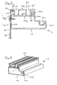
- FIG. 1 shows a preferred embodiment of the threshold 1 according to the invention in a lateral sectional view.
- the threshold 1 has a profiled support body 10, a profiled guide member 20, and a skirt 30.
- Inventive thresholds as shown in this and all subsequent figures, are arranged in lower areas of car doors or landing doors in elevator systems and serve to guide there arranged sliding door leaves.
- a lower portion of a door leaf is shown schematically simplified and designated 70.
- the support body 10 is formed as a closed tube profile and has a number of substantially right-angled curbs.
- the support body 10 has a relatively wide underside, which is designated 10a. This is adjoined (in the illustration of Figure 1 on the right side) with an upwardly open groove 10c formed extension 10b.
- the extension 10b is followed by a substantially perpendicular section 10d, which merges into a retaining lug 10e.
- the retaining lug defines a receiving section which is horizontally accessible from the left in the representation of FIG. 1 and under which, as explained below, a holding projection 22 of the guide part 20 engages.
- the retaining lug 10e closes a substantially horizontally and parallel to the bottom 10a extending upper surface 10f, which merges on its left side after forming a retaining edge 10g in a substantially vertical portion 10h, which, the profile shape concludes, again in the bottom 10a.
- the retaining lug 10e is substantially triangular in shape and oriented toward a threshold leading edge 1a, which represents the shaft side of the threshold.
- the profiled guide member 20 is largely meandering in Figure 1 and also formed with a number of right-angled curbs. It has two guide grooves 23 for guiding a lower region of a sliding door leaf 70. An elevation arranged between the guide grooves is designated by 20a. On the side of the threshold leading edge 1a, the guide member 20 has a retaining groove 21. On the opposite side, in Figure 1 right, the guide member 20 has a horizontally oriented retaining projection 22.
- an apron 30 is arranged in the region of the threshold leading edge 1a of the threshold 1. In its upper region, the skirt 30 is formed with a horizontally oriented fastening region 31 angled to the right in FIG.
- the fixing of the three components 10, 20, 30 to each other takes place in that first the guide member 20 is placed on top of the support body 10, so that the retaining projection 22 engages under the retaining lug 10e, and the left end portion of the guide member, which the retaining groove 21st contains, rests on the retaining edge 10g. Now, the upper, angled mounting portion 31 of the skirt 30 in the retaining groove 21 of the guide member 20 is inserted. Here, the vertically extending portion 32 of the skirt 30 lies flat against the region 10h of the support body 10. For complete determination or securing of the three components 10, 20, 30 to each other, it is now only necessary to attach the skirt 30 to the support body 10. This is done in the embodiment according to FIG.
- FIG. 2 shows the threshold according to FIG. 1 in a perspective view, wherein the representation of the skirt 30 is dispensed with.
- guide member 20 can be placed on the support body 10.
- a latching or securing of these two components takes place on the side facing away from the threshold leading edge 1a of the threshold 1 by engagement of the retaining lug 10e of the support body 10 and the oppositely oriented retaining projection 22 of the guide member 20.
- the embodiment shown in Figure 1 and 2 of guide member 20, Support body 10 and skirt 30 can be made of various materials, such. B. also made of simple steel or stainless steel.
- the threshold 1 according to the invention is shown in a further embodiment.
- the guide member 20 is made as a variant of aluminum.
- the construction of the support body 10 and the skirt 30 in Figure 3 correspond to those of Figure 1.
- the guide member 20 is formed as an aluminum profile, wherein it To increase the stability, for example, in the region 20a between the two guide grooves 23 or in the region of the retaining projection 22 has closed cavities.
- the guide member 20 is provided with a plurality of shallow recesses 25 for increasing the slip resistance.
- the three components of the threshold 1 are in Figure 3 in a similar manner as in Figure 1 joined together or connected to each other.
- the guide member 20 is pushed from the direction of the threshold leading edge 1a with the retaining projection 22 under the retaining lug 10e of the support body 10 and the left guide groove 23 abuts against the retaining edge 10g.
- the guide member 20 is clamped in this way between the retaining lug 10 e and the retaining edge 10 g.
- a retaining groove 21 is arranged, in which a horizontally angled fastening region 31 of the skirt 30 engages.
- the apron 30 rests against the carrier body 10 in the region of the threshold leading edge 1a (apron portion 32) and is in turn connected to the carrier body 10 via a screw connection 40.
- the threshold 1 of Figure 3 is compactly assembled in a few simple steps due to advantageous structural features of the three components.
- FIG. 4 shows the threshold according to FIG. 3 in a perspective view. From this perspective, it is easy to see how the guide part 20 can be inserted or latched into the top of the support part 10.
- the groove 10c is formed in the largely rectangular extension 10b of the supporting body 10 designed as a tubular profile. This groove 10c can also be produced by profiling and offers in particular over the length of the end regions of the support body 10 space for receiving not shown in Figure 4 sliding blocks or the like for attachment of a door frame, not shown.
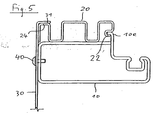
- FIG. 5 shows a further preferred embodiment of the threshold 1 according to the invention.
- This is characterized by the fact that the largely meander-shaped guide member 20, the support body 10 and the apron 30 are easy to produce by profiling of metal strips, z. B. by means of a profiling machine.
- the guide member 20 from the direction of the threshold leading edge 1a on the support body 10 is slidably and a connection of these two components is achieved in that the retaining projection 22 of the guide member 20 with the oppositely directed retaining lug 10e of the support body 10 engages ,
- the retaining lug 10e is realized in this embodiment by means of a rectangular Blechumkantung.
- the attachment portion 31 of the skirt 30 rests on the portion 24 of the guide member 20.
- the attachment region 31 of the skirt 30 comprises the upper side of the portion 24 of the guide part 20 at least partially.
- the apron 30 is fastened via a screw 40 on the support body 10.
- the skirt 30 assumes the function of a connecting or joining element for fastening the guide part 20 to the support body 10.
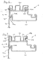
- FIG. 6 shows a further advantageous embodiment of a threshold 1 according to the invention.
- the threshold 1 in turn has three components, namely a support body 10, a skirt 30 and a guide member 20.
- a connection between the support body 10 and the guide member 20 takes place, as in the preceding figures, by means of engagement of a retaining lug 10 e of the support body 10 via a retaining projection 22 of the guide member 20.
- a connection between the support body 10 and the skirt 30 is realized in that the Supporting body 10 in the region of the threshold front edge 1a has a fixing recess 10k. This return is called S-shaped shoulder approximately in the lower corner of the support body 10 is formed.
- the skirt 30 in this case has an angled projection 32a with respect to the extension direction of the section 32.
- This projection 32a engages from below into the fixing recess 10k. In an upper region of the skirt 30, this is fastened by means of a screw connection 40 on the guide part 20. Overall, it comes in this embodiment, a secure fixing of the skirt 30 and the guide member 20 to the support body 10, wherein the interaction of the projections or profiling sections 10e, 22 and 10k, 32a ensures that these secure attachment of the components to each other by means of only mentioned a screw 40 is reached.
- FIG. 7 shows a further preferred embodiment of a threshold according to the invention.
- the support body 10 is in this case designed essentially like the support body 10 according to FIG. 6, the retaining lug 10e being formed by a U-shaped bend which is open toward the rear of the sleepers. Under this retaining lug 10e engages the horizontally to the left extending retaining projection 22 of the guide member 20th
- the support body 10 has a fastening recess 10k which is essentially S-shaped on the side facing the shaft and in which an obliquely upwardly angled projection 32a of the skirt 30 engages.
- the guide member 20 is also largely meander-shaped, wherein, analogous to the embodiments described above, two guide grooves 23 are defined.
- the upper portion of the skirt 30, here designated 33, is formed substantially in the shape of an inverted U. This area completely engages around the left section 20b of the guide part 20, likewise in the form of an inverted U-shaped section.
- a significant advantage of all illustrated embodiments of the threshold according to the invention is that they are highly resilient due to their design.
- a simple or rapid installation of the threshold in the lower region of a car or landing door can be favored that on the support body in its longitudinal direction at certain intervals recesses or punches for fixing the threshold to a shaft wall, on a floor floor, or a lower Are arranged area of a car floor.
- Such recesses or punched holes in the support body or in the guide part or in the apron can be introduced before the profiling of these components in the unfinished sheet metal strip.
- the guide member is formed as an independent component, an interchangeability of this guide member is ensured in a particularly simple manner.
Landscapes
- Engineering & Computer Science (AREA)
- Mechanical Engineering (AREA)
- Elevator Door Apparatuses (AREA)
- Maintenance And Inspection Apparatuses For Elevators (AREA)
- Lift-Guide Devices, And Elevator Ropes And Cables (AREA)
Claims (9)
- Seuil pour une ouverture de porte de cabine d'ascenseur ou de palier d'étage d'une installation d'ascenseur, destiné à guider au moins un vantail de porte mobile (70) d'une porte de cabine d'ascenseur ou d'une porte palière, comportant au moins trois composants, en particulier un corps porteur profilé (10), un composant de guidage profilé (20) et un tablier (30),
caractérisé en ce que
un premier (10) et un second (20) et le second (20) et un troisième (30) desdits au moins trois composants, encore le premier (10) et le second (20) et le premier (10) et le troisième (30) desdits au moins trois composants comprennent des tronçons profilés emboîtés l'un dans l'autre qui sont réalisés de telle sorte qu'une fixation de deux (10, 20 ; 10, 30 ; 20, 30) des trois composants l'un à l'autre permet une immobilisation de tous les composants (10, 20, 30) les uns aux autres. - Seuil selon la revendication 1, caractérisé en ce que la fixation des deux composants l'un à l'autre est réalisée au moyen d'un rivetage (40) ou d'un vissage du troisième composant, en particulier du tablier (30), sur le premier composant, en particulier sur le corps porteur profilé (10).
- Seuil selon l'une des revendications 1 ou 2, caractérisé en ce que le corps porteur profilé (10) présente au moins un bec de maintien (10e) orienté horizontalement qui coiffe une saillie de maintien (22), orientée horizontalement, du composant de guidage (20), et le composant de guidage (20) présente une gorge de maintien (21) orientée horizontalement, dans laquelle s'engage un tronçon d'extrémité (31), s'étendant horizontalement, du tablier (30), les directions d'extension de la saillie de maintien (22) et de la gorge de maintien (21) étant orientées en sens opposés l'une à l'autre.
- Seuil selon la revendication 1, caractérisé en ce que lesdits au moins trois composants (10, 20, 30) présentent des tronçons profilés emboîtés par paire l'un dans l'autre, la fixation des deux composants l'un à l'autre s'effectuant au moyen d'un clipsage de ces composants l'un sur l'autre, en particulier du tablier (30) sur le corps porteur (10).
- Seuil selon l'une des revendications précédentes, caractérisé par une gorge (10c) ménagée dans le corps porteur (10), qui est ouverte en particulier vers le haut et qui est réalisée sur le côté du corps porteur (10) opposé à l'arête avant (1a) du seuil.
- Seuil selon la revendication 5, caractérisé en ce qu'une fixation de vissage (40) pour fixer le composant de guidage (20) sur le corps porteur (10) est réalisée dans au moins une gorge de guidage (23).
- Seuil selon l'une des revendications précédentes, caractérisé en ce que le tablier (30) est muni, à son extrémité supérieure, d'au moins une zone coudée (31).
- Seuil selon l'une des revendications précédentes, caractérisé en ce que le tablier (30) est muni d'une zone à clisper (32a).
- Seuil selon l'une des revendications précédentes, caractérisé en ce que le composant de guidage (20) est pourvu, sur un côté, d'une saillie de maintien (22) et sur l'autre côté d'une gorge de maintien (21) ou d'une surface de maintien (24).
Priority Applications (3)
| Application Number | Priority Date | Filing Date | Title |
|---|---|---|---|
| AT03000599T ATE333557T1 (de) | 2003-01-14 | 2003-01-14 | Schwelle für aufzuganlage |
| DE50304283T DE50304283D1 (de) | 2003-01-14 | 2003-01-14 | Schwelle für Aufzuganlage |
| EP03000599A EP1445410B1 (fr) | 2003-01-14 | 2003-01-14 | Seuil de porte pour un système d'ascenseur |
Applications Claiming Priority (1)
| Application Number | Priority Date | Filing Date | Title |
|---|---|---|---|
| EP03000599A EP1445410B1 (fr) | 2003-01-14 | 2003-01-14 | Seuil de porte pour un système d'ascenseur |
Publications (2)
| Publication Number | Publication Date |
|---|---|
| EP1445410A1 EP1445410A1 (fr) | 2004-08-11 |
| EP1445410B1 true EP1445410B1 (fr) | 2006-07-19 |
Family
ID=32605230
Family Applications (1)
| Application Number | Title | Priority Date | Filing Date |
|---|---|---|---|
| EP03000599A Expired - Fee Related EP1445410B1 (fr) | 2003-01-14 | 2003-01-14 | Seuil de porte pour un système d'ascenseur |
Country Status (3)
| Country | Link |
|---|---|
| EP (1) | EP1445410B1 (fr) |
| AT (1) | ATE333557T1 (fr) |
| DE (1) | DE50304283D1 (fr) |
Families Citing this family (8)
| Publication number | Priority date | Publication date | Assignee | Title |
|---|---|---|---|---|
| DE202011105571U1 (de) * | 2011-09-09 | 2012-12-12 | Elevator Trading Gmbh | Türschwellenkörper für eine Schiebetür |
| CN102501031B (zh) * | 2011-12-01 | 2013-09-11 | 张家港市天力达机电有限公司 | 一种电梯地坎的制造方法 |
| CN103910265B (zh) * | 2014-04-29 | 2016-08-24 | 苏州中远电梯有限公司 | 一种电梯导轨支撑座结构 |
| WO2015186189A1 (fr) * | 2014-06-03 | 2015-12-10 | 三菱電機株式会社 | Seuil d'ascenseur |
| WO2016083922A1 (fr) * | 2014-11-27 | 2016-06-02 | Sematic S.P.A. | Procédé pour la fabrication d'un seuil pour une porte d'ascenseur et seuil |
| IT201900001073A1 (it) * | 2019-01-24 | 2020-07-24 | Wittur Holding Gmbh | Soglia per porta di ascensore |
| US20220348440A1 (en) * | 2019-09-30 | 2022-11-03 | Inventio Ag | Door frame for an elevator system |
| CN111483909B (zh) * | 2020-04-23 | 2021-12-17 | 浙江富士美电梯有限公司 | 一种一体式折弯地坎 |
Family Cites Families (5)
| Publication number | Priority date | Publication date | Assignee | Title |
|---|---|---|---|---|
| GB826175A (en) * | 1956-02-29 | 1959-12-31 | Otis Elevator Co | Elevator entrance sills |
| JPH0925080A (ja) * | 1995-07-07 | 1997-01-28 | Otis Elevator Co | エレベーターの敷居構造 |
| IT1285848B1 (it) * | 1996-04-22 | 1998-06-24 | Kone Oy | Soglia per una porta di pianerottolo per un elevatore. |
| JPH11263565A (ja) * | 1998-03-17 | 1999-09-28 | Hitachi Building Systems Co Ltd | エレベータの敷居 |
| GB2387164B (en) * | 2002-04-04 | 2005-08-24 | Sematic Italia Spa | Footplate for use in lifts |
-
2003
- 2003-01-14 EP EP03000599A patent/EP1445410B1/fr not_active Expired - Fee Related
- 2003-01-14 AT AT03000599T patent/ATE333557T1/de active
- 2003-01-14 DE DE50304283T patent/DE50304283D1/de not_active Expired - Lifetime
Also Published As
| Publication number | Publication date |
|---|---|
| ATE333557T1 (de) | 2006-08-15 |
| DE50304283D1 (de) | 2006-08-31 |
| EP1445410A1 (fr) | 2004-08-11 |
Similar Documents
| Publication | Publication Date | Title |
|---|---|---|
| EP3401496B1 (fr) | Rail de guidage pour une installation de protection solaire et installation de protection solaire correspondante | |
| WO2010046175A2 (fr) | Tiroir et outil pour assujettir le fond d'un tiroir | |
| EP4010554B1 (fr) | Ferrure de porte coulissante, meuble et procédé d'assemblage d'une ferrure de porte coulissante | |
| EP2606766A1 (fr) | Guidage d'extraction pour tiroirs coulissants avec crochet de préhension | |
| EP3496571A1 (fr) | Châssis destiné à un tiroir | |
| EP1445410B1 (fr) | Seuil de porte pour un système d'ascenseur | |
| EP0805243B1 (fr) | Attache en plusieurs parties pour façades | |
| DE19740603C2 (de) | Stulpschienenbefestigung | |
| EP2754803A2 (fr) | Crémone de fenêtre ou de porte | |
| DE3140855A1 (de) | Vorrichtung zur betaetigung einer ausstellschere fuer die fluegel von fenstern, tueren oder dergleichen | |
| EP2754805A2 (fr) | Tringle de verrouillage pour une crémone | |
| EP3816383B1 (fr) | Agencement de porte coulissante | |
| EP2759666B1 (fr) | Ferrure avec élément de profilé | |
| DE102014007699B3 (de) | Schwingscharnier für ein Fenster, insbesondere Wohndachfenster | |
| EP2132391B1 (fr) | Ensemble tringle de crémone constitué d'au moins une tringle et d'au moins un élément de guidage de tringle | |
| DE102016004915B3 (de) | Beschlag für ein Fenster, Verfahren zum Herstellen des Beschlags sowie entsprechendes Fenster | |
| EP2754802A2 (fr) | Crémone de fenêtre ou de porte | |
| DE19734647B4 (de) | Beschlagteil an einem Flügel oder einem festen Rahmen eines Fensters, einer Tür od. dgl. | |
| EP2754810B1 (fr) | Paroi de séparation | |
| AT500181A2 (de) | Tür- oder fensterbeschlag | |
| DE102018106422A1 (de) | Rollladenkasten | |
| EP2698334B1 (fr) | Système de rails pour portes coulissantes d'ascenseurs | |
| DE102005032063B3 (de) | Beschlag zur Klemmbefestigung einer Glasscheibe | |
| EP3674507B1 (fr) | Élément d'insertion, installation de porte pourvue d'élément d'insertion et procédé de montage d'un élément d'insertion | |
| EP3674508B1 (fr) | Élément d'insertion, installation de porte pourvue d'élément d'insertion et procédé de montage d'un élément d'insertion |
Legal Events
| Date | Code | Title | Description |
|---|---|---|---|
| PUAI | Public reference made under article 153(3) epc to a published international application that has entered the european phase |
Free format text: ORIGINAL CODE: 0009012 |
|
| AK | Designated contracting states |
Kind code of ref document: A1 Designated state(s): AT BE BG CH CY CZ DE DK EE ES FI FR GB GR HU IE IT LI LU MC NL PT SE SI SK TR |
|
| AX | Request for extension of the european patent |
Extension state: AL LT LV MK RO |
|
| 17P | Request for examination filed |
Effective date: 20040929 |
|
| 17Q | First examination report despatched |
Effective date: 20041115 |
|
| AKX | Designation fees paid |
Designated state(s): AT DE FR GB |
|
| RBV | Designated contracting states (corrected) |
Designated state(s): AT DE FR GB |
|
| GRAP | Despatch of communication of intention to grant a patent |
Free format text: ORIGINAL CODE: EPIDOSNIGR1 |
|
| GRAS | Grant fee paid |
Free format text: ORIGINAL CODE: EPIDOSNIGR3 |
|
| GRAA | (expected) grant |
Free format text: ORIGINAL CODE: 0009210 |
|
| AK | Designated contracting states |
Kind code of ref document: B1 Designated state(s): AT DE FR GB |
|
| REG | Reference to a national code |
Ref country code: GB Ref legal event code: FG4D Free format text: NOT ENGLISH |
|
| REF | Corresponds to: |
Ref document number: 50304283 Country of ref document: DE Date of ref document: 20060831 Kind code of ref document: P |
|
| GBT | Gb: translation of ep patent filed (gb section 77(6)(a)/1977) |
Effective date: 20061018 |
|
| ET | Fr: translation filed | ||
| PLBE | No opposition filed within time limit |
Free format text: ORIGINAL CODE: 0009261 |
|
| STAA | Information on the status of an ep patent application or granted ep patent |
Free format text: STATUS: NO OPPOSITION FILED WITHIN TIME LIMIT |
|
| 26N | No opposition filed |
Effective date: 20070420 |
|
| REG | Reference to a national code |
Ref country code: FR Ref legal event code: PLFP Year of fee payment: 13 |
|
| PGFP | Annual fee paid to national office [announced via postgrant information from national office to epo] |
Ref country code: DE Payment date: 20150121 Year of fee payment: 13 |
|
| PGFP | Annual fee paid to national office [announced via postgrant information from national office to epo] |
Ref country code: GB Payment date: 20150121 Year of fee payment: 13 Ref country code: AT Payment date: 20150122 Year of fee payment: 13 Ref country code: FR Payment date: 20150122 Year of fee payment: 13 |
|
| REG | Reference to a national code |
Ref country code: DE Ref legal event code: R119 Ref document number: 50304283 Country of ref document: DE |
|
| REG | Reference to a national code |
Ref country code: AT Ref legal event code: MM01 Ref document number: 333557 Country of ref document: AT Kind code of ref document: T Effective date: 20160114 |
|
| GBPC | Gb: european patent ceased through non-payment of renewal fee |
Effective date: 20160114 |
|
| REG | Reference to a national code |
Ref country code: FR Ref legal event code: ST Effective date: 20160930 |
|
| PG25 | Lapsed in a contracting state [announced via postgrant information from national office to epo] |
Ref country code: GB Free format text: LAPSE BECAUSE OF NON-PAYMENT OF DUE FEES Effective date: 20160114 Ref country code: DE Free format text: LAPSE BECAUSE OF NON-PAYMENT OF DUE FEES Effective date: 20160802 |
|
| PG25 | Lapsed in a contracting state [announced via postgrant information from national office to epo] |
Ref country code: AT Free format text: LAPSE BECAUSE OF NON-PAYMENT OF DUE FEES Effective date: 20160114 Ref country code: FR Free format text: LAPSE BECAUSE OF NON-PAYMENT OF DUE FEES Effective date: 20160201 |