EP1444937A1 - Grill unit and cooking apparatus with the same - Google Patents
Grill unit and cooking apparatus with the same Download PDFInfo
- Publication number
- EP1444937A1 EP1444937A1 EP03257375A EP03257375A EP1444937A1 EP 1444937 A1 EP1444937 A1 EP 1444937A1 EP 03257375 A EP03257375 A EP 03257375A EP 03257375 A EP03257375 A EP 03257375A EP 1444937 A1 EP1444937 A1 EP 1444937A1
- Authority
- EP
- European Patent Office
- Prior art keywords
- grill
- pipes
- grill pipes
- water
- water tanks
- Prior art date
- Legal status (The legal status is an assumption and is not a legal conclusion. Google has not performed a legal analysis and makes no representation as to the accuracy of the status listed.)
- Granted
Links
Images


Classifications
-
- A—HUMAN NECESSITIES
- A47—FURNITURE; DOMESTIC ARTICLES OR APPLIANCES; COFFEE MILLS; SPICE MILLS; SUCTION CLEANERS IN GENERAL
- A47J—KITCHEN EQUIPMENT; COFFEE MILLS; SPICE MILLS; APPARATUS FOR MAKING BEVERAGES
- A47J37/00—Baking; Roasting; Grilling; Frying
- A47J37/06—Roasters; Grills; Sandwich grills
- A47J37/0694—Broiling racks
Definitions
- the present invention relates, in general, to a grill unit and cooking apparatus with the same and, more particularly, to a grill unit and cooking apparatus with the same, which prevents noise from being generated during cooking.
- meat or processed meat such as sausage
- meat or processed meat is most delicious when grilled. Therefore, persons enjoy cooking meat or processed meat using a cooking apparatus with a grill unit and eating the cooked meat or processed meat.
- the cooking apparatus for this kind of cooking includes a heating unit for directly applying heat to food, and a grill unit mounted on top of the heating unit to support food while spacing the food apart from the heating unit.
- This structure allows food put on the grill unit to be heated by heat transferred from the heating unit.
- high temperature heat is directly transferred from the heating unit to the grill unit, so the part of food in contact with the grill unit easily burns, thus deteriorating the taste of the food and negatively affecting the health of those eating the burned food.
- An aim of the present invention is to provide a grill unit which reduces burning of food. Further, it is an aim to provide such a grill unit which is quiet in operation.
- the present invention provides a grill unit and cooking apparatus with the same, which allows water contained in grill pipes to continuously flow in one direction during cooking, thus minimizing the amount of water vapor generated in the grill pipes and preventing noise from being generated by water vapor discharged from the grill pipes to water tanks.
- a grill unit including a plurality of grill pipes, each grill pipe having two ends; water tanks connected to both ends of the grill pipes to supply water to the grill pipes; and soundproofing covers positioned around both ends of the grill pipes that are inserted into the water tanks.
- the one of the ends of each of the grill pipes is partially obstructed by a corresponding one of the projections while being spaced apart from the corresponding projection to enable water contained in each grill pipe to flow therein in one direction.
- the ends of the plurality of grill pipes are alternately and partially obstructed by the corresponding projections, the plurality of projections being alternately arranged in both of the water tanks.
- the grill pipes are formed in such a way that both ends of the grill pipes, which are open, face top surfaces of the water tanks; and the soundproofing covers each include a top surface opposite the open ends of the grill pipes to intercept water vapor discharged from the grill pipes, and at least one side surface downwardly bent and extended from an edge of each top surface by a predetermined length and open at a lower end thereof.
- the grill pipes are formed in such a way that both ends of the grill pipes, which are open, face side surfaces of the water tanks; and the soundproofing covers each include a top surface positioned over upper surfaces of the ends of the grill pipes to intercept water vapor discharged from the grill pipes, and a side surface opposite the open ends of the grill pipes and open at a lower end thereof.
- Each of the water tanks includes a cover installed on an open upper portion thereof to selectively open and close each of the water tanks.
- Each of the soundproofing covers extends in a longitudinal direction to the water tanks.
- the ends of the plurality of grill pipes are inserted into the water tanks.
- a cooking apparatus with a grill unit including a cabinet having at least one heater; and a grill unit mounted on a top surface of the cabinet to support food, the grill unit having a plurality of grill pipes, water tanks connected to both ends of the grill pipes to supply water to the grill pipes, and soundproofing covers positioned around both ends of the grill pipes that are inserted into the water tanks.
- a grill unit including a plurality of grill pipes, each grill pipe having two ends; water tanks connected to both ends of the grill pipes to supply water to the grill pipes, both ends of the grill pipes facing side surfaces of the water tanks; and soundproofing covers positioned around both ends of the grill pipes that are inserted into the water tanks, the soundproofing covers each including a top surface positioned over upper surfaces of respective ends of the grill pipes to intercept water vapor discharged from the grill pipes, and a side surface opposite the respective ends of the grill pipes and open at a lower end thereof, wherein the grill pipes are prevented from overheating by allowing water to flow into the grill pipes from the water tanks, thereby preventing food contacting the grill pipes from burning when the grill pipes are heated and slowing an increase in temperature of the grill pipes to reduce an amount of water vapor generated, and wherein the soundproofing covers positioned around the ends of the grill pipes and spaced apart from the grill pipes prevent noise from being generated when water vapor, which is produced in the grill pipes when water in the
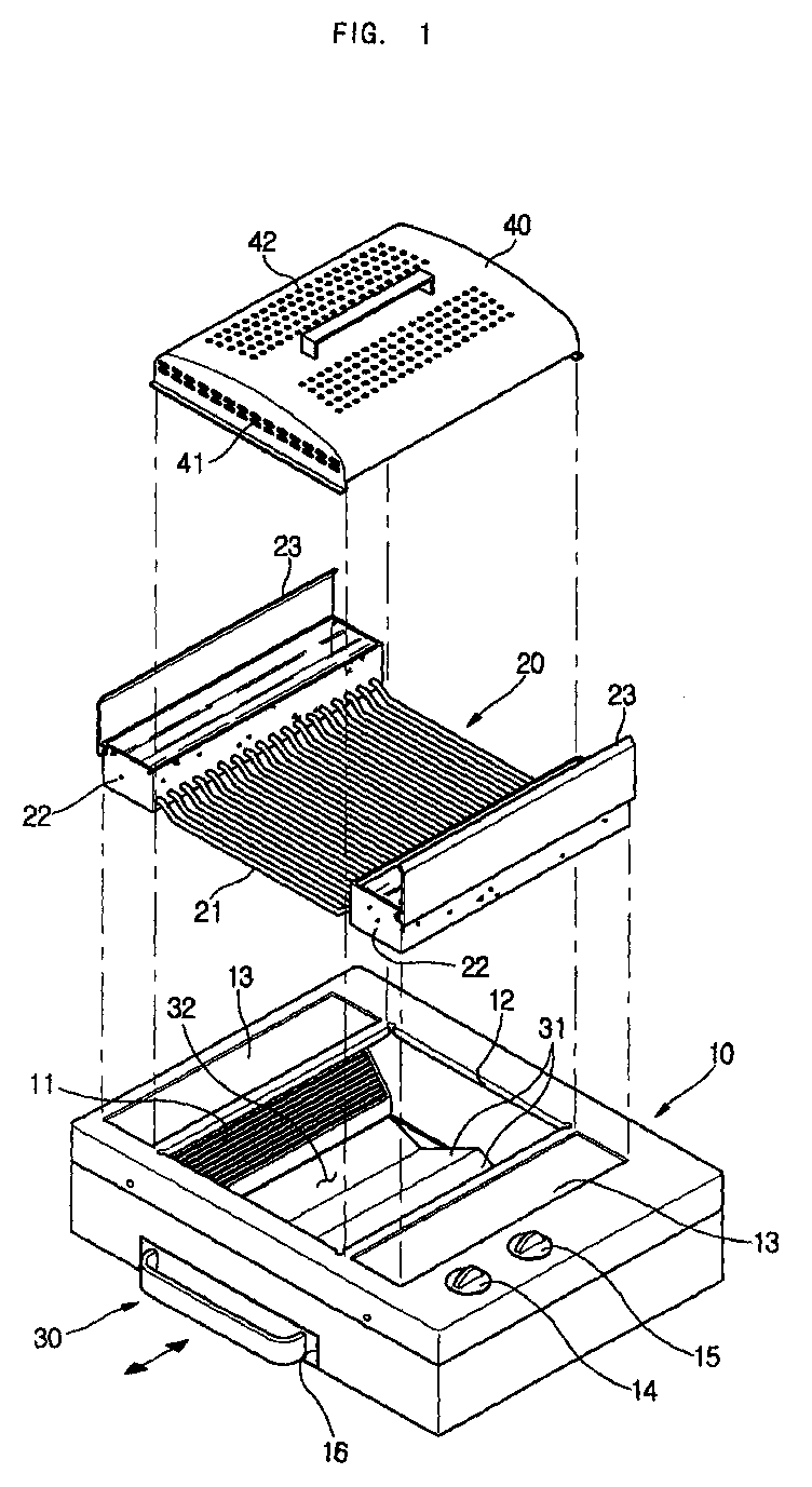
- a cooking apparatus with a grill unit includes a cabinet 10 formed in a box shape, and a grill unit 20 mounted on a top of the cabinet 10 to grill food put on the grill unit 20. Further, the cooking apparatus includes a plurality of heaters 11 mounted in the cabinet 10 to heat food put on the grill unit 20, a heat reflecting member 30 that guides the heat from the heaters 11 to the food on the grill unit 20 and collects oil dripping from the food, and a cover member 40 that covers the upper portion of the grill unit 20 and has a plurality of holes 41 and 42 perforated therethrough.
- the cabinet 10 has an opening 12 formed in the top thereof to allow heat generated by the heaters 11 mounted in the cabinet 10 to be transferred to the grill unit 20.
- Grill seats 13, each with a predetermined area, are formed on both sides of the top surface of the cabinet 10 around the opening 12 to allow the grill unit 20 to be seated thereon.
- a timer switch 14 and a power switch 15 are provided at a certain portion of a top surface of the cabinet 10 to control the heating time and the heating temperature of the heaters 11, respectively.
- An opening 16 is formed in a lower portion of the front of the cabinet 10 so that the heat reflecting member 30 may be moved into and out of the cabinet 10 through the opening 16, similar to the operation of a drawer.
- the heaters 11 are set within both sides of the cabinet 10, that is, below the grill seats 13, to heat food put on the grill unit 20, and are inclined at a predetermined angle such that heating surfaces of the heaters 11 face the opening 12 formed in the top of the cabinet 10.
- the heaters 11 each include a ceramic member in which heating elements are encapsulated to generate infrared rays with a high temperature.
- the heaters 11 may be implemented as gas heaters using gas, or as trays for holding charcoal.
- the heat reflecting member 30 is constructed such that its axial center portion is projected upward to form a hill shape with a triangular cross-section, and both projected surfaces form reflecting surfaces 31 to allow heat generated by the heaters 11 to be reflected to the grill unit 20 arranged above the heaters 11. Further, recesses 32 are formed at bottoms of both projected surfaces to collect oil dripping from food put on the grill unit 20. Further, although not shown in Figure 1, a predetermined amount of water is contained in the heat reflecting member 30 to prevent the temperatures of the recesses 32 and the reflecting surfaces 31 from increasing excessively, thus preventing oil collected in the recesses 32 from burning or adhering to the recesses 32.
- the grill unit 20 includes a plurality of grill pipes 21 arranged in parallel with each other while being spaced apart from each other, water tanks 22 connected to both side ends of the grill pipes 21 to supply water into the grill pipes 21 and provided with bottom surfaces seated on the grill seats 13 of the top surface of the cabinet 10, and covers 23 to selectively open and close upper portions of the water tanks 22.
- the grill unit 20 of the present invention is designed such that the grill pipes 21 are made of metallic material and the water tanks 22 on both sides thereof are manufactured through injection molding of a resin material.
- a lower portion 22a of each of the water tanks 22, into which the grill pipes 21 are inserted is thicker than a side portion 22b thereof.
- Both side ends of each of the grill pipes 21 inserted into the lower portions 22a of the water tanks 22 include a laterally extended part 21a that is laterally extended by a predetermined length, and an upwardly extended part 21b that is upwardly bent and extended from the laterally extended part 21a and open at the top thereof to interface with an inside of each of the water tanks 22.
- This construction reinforces the rigidity of portions where both side ends of the grill pipes 21 and the water tanks 22 are connected to each other, which are kept watertight.
- each of the grill pipes 21 is provided with a horizontally extended part 21d on which food is placed.
- the horizontally extended part 21d is bent to be positioned lower than both side ends of the grill pipes 21 connected to the water tanks 22 so that the food is positioned near the heaters 11 arranged below the food. That is, each of the grill pipes 21 is provided with two inclined parts 21c downwardly bent at a predetermined angle and extended from end parts connected to the water tanks 22.
- Each of the grill pipes 21 is bent to be horizontally extended between the inclined parts 21c, so that the horizontally extended part 21d on which the food is placed is lower than the water tanks 20.
- the above-described construction of the grill unit 20 prevents the grill pipes 21 from overheating by allowing water to flow into the grill pipes 21 from the water tanks 22, even though the grill pipes 21 are heated by heat transferred from the heaters 11 arranged below the grill unit 20 when the user grills food, thereby preventing the part of food in contact with the grill pipes 21 from burning.
- soundproofing covers 25 are positioned around the ends of the grill pipes 21 while being spaced apart from the grill pipes 21 by a predetermined distance to prevent noise from being generated when water vapor, which is generated when water contained in the grill pipes 21 boils, is discharged to the water tanks 22.
- the soundproofing covers 25 extend in the longitudinal direction of the water tanks 25 and are positioned around the ends of the grill pipes 21.
- the soundproofing covers 25 each include a top surface 25a arranged opposite to upwardly open ends of the grill pipes 21 to intercept discharged water vapor, and side surfaces 25b downwardly bent and extended from edges of the top surface 25a by a predetermined length.
- the soundproofing covers 25 are constructed such that a fixing part 25c connected to a lower end of one of the side surfaces 25b is fixed to an inner lower surface of each water tank 22, and a lower end of the other side surface 25b is open while being spaced apart from the inner lower surface of each water tank 22 to allow water vapor to be discharged through the open end.
- This construction of the soundproofing covers 25 allows water vapor, discharged from the grill pipes 21 to the water tanks 22 at a predetermined pressure, to be intercepted by the soundproofing covers 25, thus reducing noise generated due to the discharge pressure. Further, this construction enables an air layer to be formed while discharged water vapor collects in the soundproofing covers 25 by a predetermined amount when the water vapor is discharged to the ends of the grill pipes 21, thereby increasing an overall soundproofing effect by the air layer.
- the grill unit 20 of the present invention is constructed such that one of the side ends of each grill pipe 21 is partially obstructed by a projection 26 downwardly formed on the inner surface of one of the soundproofing covers 25 while being spaced apart from the projection 26 by a predetermined distance.
- This construction of the waterproofing covers 25 allows one side end of each grill pipe 21 to be partially obstructed by one of the projections 26, so that water vapor, generated in the grill pipe 21 when water contained in the grill pipe 21 boils, is discharged to the other side end of each grill pipe 21 that is not partially obstructed by the projection 26, thus enabling water contained in the grill pipe 21 to continuously flow in the grill pipe 21 in only one direction.
- the construction of the soundproofing covers 25 slows the increase in temperature of the grill pipe 21 and reduces the amount of generated water vapor.
- the ends of the grill pipes 21, which are arranged in a line in each water tank 22, are alternately and partially obstructed by the projections 26 downwardly formed on the soundproofing covers 25. That is, the projections 26 formed on the soundproofing covers 25 are formed at intervals corresponding to twice the distance between neighboring grill pipes 21 to alternately and partially obstruct the ends of the corresponding grill pipes 21.
- the soundproofing covers 25 in the water tanks 22 are formed in the same overall shape. However, as shown in Figure 3, the projections 26 partially obstruct only one side end of each of the grill pipes 21 while being spaced apart from the one side end. As shown in Figure 2, this construction allows water contained in neighboring grill pipes 21 to flow in opposite directions (in the directions indicated by arrows in Figure 2), thus enabling water to be continuously circulated while maintaining the water levels of both the water tanks 22.
- FIG 7 illustrates another embodiment of the grill unit 20 of the present invention.
- both open side ends of each grill pipe 21 face side surfaces of the water tanks 22, respectively, and soundproofing covers 28 are positioned around both side ends of each grill pipe 21.
- the soundproofing covers 28 each include a top surface 28a and a side surface 28b.
- the top surface 28a is fixed to one side surface of the water tank 22, while being positioned over an upper surface of an end portion of each grill pipe 21 to intercept water vapor discharged from each grill pipe 21.
- the side surface 28b is downwardly bent and extended from the top surface 28a to be opposite the open end of each grill pipe 21, and is open at a lower end thereof.
- a projection 29 is formed on the side surface 28b of one of the soundproofing covers 28 to partially obstruct one side end of each grill pipe 21, while being spaced apart from the one side end thereof.
- Each projection 29 is arranged as described above in the first embodiment to obtain the same water-cooling effect as the above embodiment.
- the present invention provides a grill unit and cooking apparatus with the same, which reduces noise generated due to discharged water vapor through the use of soundproofing covers installed within water tanks, even though water vapor generated in grill pipes is discharged to the water tanks, thus preventing noise from being generated.
- the present invention is advantageous in that the grill unit continuously circulates water contained in neighboring grill pipes, while allowing the water to flow in the grill pipes in opposite directions, to slow the increase in temperature of the grill pipes, which reduces the amount of water vapor generated in the grill pipes and reduces noise generated.
Abstract
Description
- The present invention relates, in general, to a grill unit and cooking apparatus with the same and, more particularly, to a grill unit and cooking apparatus with the same, which prevents noise from being generated during cooking.
- Generally, it is well known that meat or processed meat, such as sausage, is most delicious when grilled. Therefore, persons enjoy cooking meat or processed meat using a cooking apparatus with a grill unit and eating the cooked meat or processed meat.
- The cooking apparatus for this kind of cooking includes a heating unit for directly applying heat to food, and a grill unit mounted on top of the heating unit to support food while spacing the food apart from the heating unit. This structure allows food put on the grill unit to be heated by heat transferred from the heating unit. However, when cooking is performed using the cooking apparatus equipped with a grill unit, high temperature heat is directly transferred from the heating unit to the grill unit, so the part of food in contact with the grill unit easily burns, thus deteriorating the taste of the food and negatively affecting the health of those eating the burned food.
- An aim of the present invention is to provide a grill unit which reduces burning of food. Further, it is an aim to provide such a grill unit which is quiet in operation.
- Other aims and/or advantages of the invention will be set forth in part in the description that follows and, in part, will be obvious from the description, or may be learned by practice of the invention.
- According to the present invention there is provided an apparatus and method as set forth in the appended claims. Preferred features of the invention will be apparent from the dependent claims, and the description which follows.
- The present invention provides a grill unit and cooking apparatus with the same, which allows water contained in grill pipes to continuously flow in one direction during cooking, thus minimizing the amount of water vapor generated in the grill pipes and preventing noise from being generated by water vapor discharged from the grill pipes to water tanks.
- In one aspect of the present invention, there is provided a grill unit including a plurality of grill pipes, each grill pipe having two ends; water tanks connected to both ends of the grill pipes to supply water to the grill pipes; and soundproofing covers positioned around both ends of the grill pipes that are inserted into the water tanks.
- Preferably, the one of the ends of each of the grill pipes is partially obstructed by a corresponding one of the projections while being spaced apart from the corresponding projection to enable water contained in each grill pipe to flow therein in one direction.
- The ends of the plurality of grill pipes are alternately and partially obstructed by the corresponding projections, the plurality of projections being alternately arranged in both of the water tanks.
- The grill pipes are formed in such a way that both ends of the grill pipes, which are open, face top surfaces of the water tanks; and the soundproofing covers each include a top surface opposite the open ends of the grill pipes to intercept water vapor discharged from the grill pipes, and at least one side surface downwardly bent and extended from an edge of each top surface by a predetermined length and open at a lower end thereof.
- The grill pipes are formed in such a way that both ends of the grill pipes, which are open, face side surfaces of the water tanks; and the soundproofing covers each include a top surface positioned over upper surfaces of the ends of the grill pipes to intercept water vapor discharged from the grill pipes, and a side surface opposite the open ends of the grill pipes and open at a lower end thereof.
- Each of the water tanks includes a cover installed on an open upper portion thereof to selectively open and close each of the water tanks.
- Each of the soundproofing covers extends in a longitudinal direction to the water tanks. The ends of the plurality of grill pipes are inserted into the water tanks.
- In another aspect of the present invention, there is provided a cooking apparatus with a grill unit, including a cabinet having at least one heater; and a grill unit mounted on a top surface of the cabinet to support food, the grill unit having a plurality of grill pipes, water tanks connected to both ends of the grill pipes to supply water to the grill pipes, and soundproofing covers positioned around both ends of the grill pipes that are inserted into the water tanks.
- In another aspect according to the present invention, there is provided a grill unit including a plurality of grill pipes, each grill pipe having two ends; water tanks connected to both ends of the grill pipes to supply water to the grill pipes, both ends of the grill pipes facing side surfaces of the water tanks; and soundproofing covers positioned around both ends of the grill pipes that are inserted into the water tanks, the soundproofing covers each including a top surface positioned over upper surfaces of respective ends of the grill pipes to intercept water vapor discharged from the grill pipes, and a side surface opposite the respective ends of the grill pipes and open at a lower end thereof, wherein the grill pipes are prevented from overheating by allowing water to flow into the grill pipes from the water tanks, thereby preventing food contacting the grill pipes from burning when the grill pipes are heated and slowing an increase in temperature of the grill pipes to reduce an amount of water vapor generated, and wherein the soundproofing covers positioned around the ends of the grill pipes and spaced apart from the grill pipes prevent noise from being generated when water vapor, which is produced in the grill pipes when water in the grill pipes boils, discharges to the water tanks at a discharge pressure.
- These, together with other aspects and/or advantages that will be subsequently apparent, reside in the details of construction and operation as more fully hereinafter described and claimed, reference being had to the accompanying drawings forming a part thereof, wherein like numerals refer to like parts throughout.
- For a better understanding of the invention, and to show how embodiments of the same may be carried into effect, reference will now be made, by way of example, to the accompanying diagrammatic drawings in which:
- Figure 1 is an exploded perspective view of a cooking apparatus with a grill unit according to the present invention;
- Figure 2 is a plan view showing the construction of the grill unit of the present invention;
- Figure 3 is a sectional view of the grill unit taken along line III-III' of Figure 2;
- Figure 4 is a perspective view showing the construction of a soundproofing cover of the grill unit of the present invention;
- Figure 5 is a detailed view of portion V of Figure 3;
- Figure 6 is a detailed view of portion VI of Figure 3; and
- Figure 7 is a sectional view of showing the construction of a grill unit, according to another embodiment of the present invention.
-
- As shown in Figure 1, a cooking apparatus with a grill unit according to the preferred embodiment of the present invention includes a
cabinet 10 formed in a box shape, and agrill unit 20 mounted on a top of thecabinet 10 to grill food put on thegrill unit 20. Further, the cooking apparatus includes a plurality ofheaters 11 mounted in thecabinet 10 to heat food put on thegrill unit 20, aheat reflecting member 30 that guides the heat from theheaters 11 to the food on thegrill unit 20 and collects oil dripping from the food, and acover member 40 that covers the upper portion of thegrill unit 20 and has a plurality ofholes 41 and 42 perforated therethrough. - The
cabinet 10 has anopening 12 formed in the top thereof to allow heat generated by theheaters 11 mounted in thecabinet 10 to be transferred to thegrill unit 20.Grill seats 13, each with a predetermined area, are formed on both sides of the top surface of thecabinet 10 around the opening 12 to allow thegrill unit 20 to be seated thereon. Further, atimer switch 14 and apower switch 15 are provided at a certain portion of a top surface of thecabinet 10 to control the heating time and the heating temperature of theheaters 11, respectively. Anopening 16 is formed in a lower portion of the front of thecabinet 10 so that theheat reflecting member 30 may be moved into and out of thecabinet 10 through theopening 16, similar to the operation of a drawer. - The
heaters 11 are set within both sides of thecabinet 10, that is, below thegrill seats 13, to heat food put on thegrill unit 20, and are inclined at a predetermined angle such that heating surfaces of theheaters 11 face the opening 12 formed in the top of thecabinet 10. Theheaters 11 each include a ceramic member in which heating elements are encapsulated to generate infrared rays with a high temperature. However, theheaters 11 may be implemented as gas heaters using gas, or as trays for holding charcoal. - The
heat reflecting member 30 is constructed such that its axial center portion is projected upward to form a hill shape with a triangular cross-section, and both projected surfaces form reflectingsurfaces 31 to allow heat generated by theheaters 11 to be reflected to thegrill unit 20 arranged above theheaters 11. Further,recesses 32 are formed at bottoms of both projected surfaces to collect oil dripping from food put on thegrill unit 20. Further, although not shown in Figure 1, a predetermined amount of water is contained in theheat reflecting member 30 to prevent the temperatures of therecesses 32 and thereflecting surfaces 31 from increasing excessively, thus preventing oil collected in therecesses 32 from burning or adhering to therecesses 32. - The
grill unit 20 includes a plurality ofgrill pipes 21 arranged in parallel with each other while being spaced apart from each other,water tanks 22 connected to both side ends of thegrill pipes 21 to supply water into thegrill pipes 21 and provided with bottom surfaces seated on thegrill seats 13 of the top surface of thecabinet 10, and covers 23 to selectively open and close upper portions of thewater tanks 22. - Further, as shown in Figure 3, the
grill unit 20 of the present invention is designed such that thegrill pipes 21 are made of metallic material and thewater tanks 22 on both sides thereof are manufactured through injection molding of a resin material. As shown in Figure 5, alower portion 22a of each of thewater tanks 22, into which thegrill pipes 21 are inserted, is thicker than aside portion 22b thereof. Both side ends of each of thegrill pipes 21 inserted into thelower portions 22a of thewater tanks 22 include a laterally extendedpart 21a that is laterally extended by a predetermined length, and an upwardly extendedpart 21b that is upwardly bent and extended from the laterally extendedpart 21a and open at the top thereof to interface with an inside of each of thewater tanks 22. This construction reinforces the rigidity of portions where both side ends of thegrill pipes 21 and thewater tanks 22 are connected to each other, which are kept watertight. - As shown in Figures 3 and 5, each of the
grill pipes 21 is provided with a horizontally extendedpart 21d on which food is placed. The horizontally extendedpart 21d is bent to be positioned lower than both side ends of thegrill pipes 21 connected to thewater tanks 22 so that the food is positioned near theheaters 11 arranged below the food. That is, each of thegrill pipes 21 is provided with twoinclined parts 21c downwardly bent at a predetermined angle and extended from end parts connected to thewater tanks 22. Each of thegrill pipes 21 is bent to be horizontally extended between theinclined parts 21c, so that the horizontally extendedpart 21d on which the food is placed is lower than thewater tanks 20. - The above-described construction of the
grill unit 20 prevents thegrill pipes 21 from overheating by allowing water to flow into thegrill pipes 21 from thewater tanks 22, even though thegrill pipes 21 are heated by heat transferred from theheaters 11 arranged below thegrill unit 20 when the user grills food, thereby preventing the part of food in contact with thegrill pipes 21 from burning. - Further, as shown in Figures 3 to 5, soundproofing covers 25 are positioned around the ends of the
grill pipes 21 while being spaced apart from thegrill pipes 21 by a predetermined distance to prevent noise from being generated when water vapor, which is generated when water contained in thegrill pipes 21 boils, is discharged to thewater tanks 22. - As shown in Figures 4 to 6, the soundproofing covers 25 extend in the longitudinal direction of the
water tanks 25 and are positioned around the ends of thegrill pipes 21. The soundproofing covers 25 each include atop surface 25a arranged opposite to upwardly open ends of thegrill pipes 21 to intercept discharged water vapor, andside surfaces 25b downwardly bent and extended from edges of thetop surface 25a by a predetermined length. Further, thesoundproofing covers 25 are constructed such that afixing part 25c connected to a lower end of one of theside surfaces 25b is fixed to an inner lower surface of eachwater tank 22, and a lower end of theother side surface 25b is open while being spaced apart from the inner lower surface of eachwater tank 22 to allow water vapor to be discharged through the open end. This construction of the soundproofing covers 25 allows water vapor, discharged from thegrill pipes 21 to thewater tanks 22 at a predetermined pressure, to be intercepted by the soundproofing covers 25, thus reducing noise generated due to the discharge pressure. Further, this construction enables an air layer to be formed while discharged water vapor collects in the soundproofing covers 25 by a predetermined amount when the water vapor is discharged to the ends of thegrill pipes 21, thereby increasing an overall soundproofing effect by the air layer. - Further, as shown in Figure 3, the
grill unit 20 of the present invention is constructed such that one of the side ends of eachgrill pipe 21 is partially obstructed by aprojection 26 downwardly formed on the inner surface of one of the soundproofing covers 25 while being spaced apart from theprojection 26 by a predetermined distance. This construction of the waterproofing covers 25 allows one side end of eachgrill pipe 21 to be partially obstructed by one of theprojections 26, so that water vapor, generated in thegrill pipe 21 when water contained in thegrill pipe 21 boils, is discharged to the other side end of eachgrill pipe 21 that is not partially obstructed by theprojection 26, thus enabling water contained in thegrill pipe 21 to continuously flow in thegrill pipe 21 in only one direction. Through this water flow, the construction of the soundproofing covers 25 slows the increase in temperature of thegrill pipe 21 and reduces the amount of generated water vapor. - Further, as shown in Figure 4, the ends of the
grill pipes 21, which are arranged in a line in eachwater tank 22, are alternately and partially obstructed by theprojections 26 downwardly formed on thesoundproofing covers 25. That is, theprojections 26 formed on thesoundproofing covers 25 are formed at intervals corresponding to twice the distance between neighboringgrill pipes 21 to alternately and partially obstruct the ends of thecorresponding grill pipes 21. The soundproofing covers 25 in thewater tanks 22 are formed in the same overall shape. However, as shown in Figure 3, theprojections 26 partially obstruct only one side end of each of thegrill pipes 21 while being spaced apart from the one side end. As shown in Figure 2, this construction allows water contained in neighboringgrill pipes 21 to flow in opposite directions (in the directions indicated by arrows in Figure 2), thus enabling water to be continuously circulated while maintaining the water levels of both thewater tanks 22. - Figure 7 illustrates another embodiment of the
grill unit 20 of the present invention. In the embodiment shown in Figure 7, both open side ends of eachgrill pipe 21 face side surfaces of thewater tanks 22, respectively, and soundproofing covers 28 are positioned around both side ends of eachgrill pipe 21. The soundproofing covers 28 each include atop surface 28a and aside surface 28b. Thetop surface 28a is fixed to one side surface of thewater tank 22, while being positioned over an upper surface of an end portion of eachgrill pipe 21 to intercept water vapor discharged from eachgrill pipe 21. Theside surface 28b is downwardly bent and extended from thetop surface 28a to be opposite the open end of eachgrill pipe 21, and is open at a lower end thereof. Aprojection 29 is formed on theside surface 28b of one of the soundproofing covers 28 to partially obstruct one side end of eachgrill pipe 21, while being spaced apart from the one side end thereof. Eachprojection 29 is arranged as described above in the first embodiment to obtain the same water-cooling effect as the above embodiment. - As is apparent from the above description, the present invention provides a grill unit and cooking apparatus with the same, which reduces noise generated due to discharged water vapor through the use of soundproofing covers installed within water tanks, even though water vapor generated in grill pipes is discharged to the water tanks, thus preventing noise from being generated.
- Further, the present invention is advantageous in that the grill unit continuously circulates water contained in neighboring grill pipes, while allowing the water to flow in the grill pipes in opposite directions, to slow the increase in temperature of the grill pipes, which reduces the amount of water vapor generated in the grill pipes and reduces noise generated.
- Although a few preferred embodiments have been shown and described, it will be appreciated by those skilled in the art that various changes and modifications might be made without departing from the scope of the invention, as defined in the appended claims.
- Attention is directed to all papers and documents which are filed concurrently with or previous to this specification in connection with this application and which are open to public inspection with this specification, and the contents of all such papers and documents are incorporated herein by reference.
- All of the features disclosed in this specification (including any accompanying claims, abstract and drawings), and/or all of the steps of any method or process so disclosed, may be combined in any combination, except combinations where at least some of such features and/or steps are mutually exclusive.
- Each feature disclosed in this specification (including any accompanying claims, abstract and drawings) may be replaced by alternative features serving the same, equivalent or similar purpose, unless expressly stated otherwise. Thus, unless expressly stated otherwise, each feature disclosed is one example only of a generic series of equivalent or similar features.
- The invention is not restricted to the details of the foregoing embodiment(s). The invention extends to any novel one, or any novel combination, of the features disclosed in this specification (including any accompanying claims, abstract and drawings), or to any novel one, or any novel combination, of the steps of any method or process so disclosed.
Claims (23)
- A grill unit, comprising:a plurality of grill pipes (21), each grill pipe having two ends;water tanks (22) connected to both ends of the grill pipes (21) to supply water to the grill pipes (21); andsoundproofing covers (25) positioned around both ends of the grill pipes (21) that are inserted into the water tanks (22).
- The grill unit according to claim 1, further comprising a plurality of projections (26) formed on an inner surface of each of the soundproofing covers (25), wherein one of the ends of each of the grill pipes (21) is partially obstructed by a corresponding one of the projections (26) while being spaced apart from the corresponding projection to enable water contained in each grill pipe to flow therein in one direction.
- The grill unit according to claim 2, wherein the ends of the plurality of grill pipes (21) are alternately and partially obstructed by the corresponding projections (26), the plurality of projections (26) being alternately arranged in both of the water tanks (22).
- The grill unit according to any preceding claim, wherein:both ends of the grill pipes (21), which are open, face top surfaces of the water tanks (22); andthe soundproofing covers (25) comprise a top surface (25a) opposite the open ends of the grill pipes (21) to intercept water vapor discharged from the grill pipes (21), and at least one side surface (25b) downwardly bent and extended from an edge of each top surface (25a) by a predetermined length and open at a lower end thereof.
- The grill unit according to any preceding claim, wherein:both ends of the grill pipes (21), which are open, face side surfaces of the water tanks (22); andthe soundproofing covers (25) comprise a top surface (25a) positioned over upper surfaces of the ends of the grill pipes (21) to intercept water vapor discharged from the grill pipes (21), and a side surface (25b) opposite the open ends of the grill pipes (21) and open at a lower end thereof.
- The grill unit according to claim 5, further comprising a plurality of projections (26) formed on a side surface (25b) of one of the soundproofing covers (25), wherein one of the ends of each of the grill pipes (21) is partially obstructed by a corresponding one of the projections (26) while being spaced apart from the corresponding projection to enable water contained in each grill pipe to flow therein in one direction.
- The grill unit according to any preceding claim, wherein each of the water tanks (22) comprises a cover (40) installed on an open upper portion thereof to selectively open and close each of the water tanks (22).
- The grill unit according to any preceding claim, wherein each of the soundproofing covers (25) extends in a longitudinal direction to the water tanks (22) and are positioned around the ends of the plurality of grill pipes (21) inserted into the water tanks (22).
- A cooking apparatus with a grill unit, comprising:a cabinet having at least one heater; anda grill unit mounted on a top surface (25a) of the cabinet to support food, the grill unit having a plurality of grill pipes (21), water tanks (22) connected to both ends of the grill pipes (21) to supply water to the grill pipes (21), and soundproofing covers (25) positioned around both ends of the grill pipes (21) that are inserted into the water tanks (22).
- The cooking apparatus according to claim 9, further comprising a plurality of projections (26) formed on an inner surface of each of the soundproofing covers (25), wherein one of the ends of each of the grill pipes (21) is partially obstructed by a corresponding one of the projections (26) while being spaced apart from the corresponding projection to enable water contained in each grill pipe to flow therein in one direction.
- The cooking apparatus according to claim 10, wherein the ends of the plurality of grill pipes (21) are alternately and partially obstructed by the corresponding projections (26), the plurality of projections (26) being alternately arranged in both of the water tanks (22).
- The cooking apparatus according to claim 9, 10 or 11, wherein:both ends of the grill pipes (21), which are open, face top surfaces of the water tanks (22); andthe soundproofing covers (25) each comprise a top surface (25a) opposite the open ends of the grill pipes (21) to intercept water vapor discharged from the grill pipes (21), and at least one side surface (25b) downwardly bent and extended from an edge of each top surface (25a) by a predetermined length and open at a lower end thereof.
- The cooking apparatus according to any of claims 9 to 12, wherein:both ends of the grill pipes (21), which are open, face side surfaces of the water tanks (22); andthe soundproofing covers (25) each comprise a top surface (25a) positioned over upper surfaces of the ends of the grill pipes (21) to intercept water vapor discharged from the grill pipes (21), and a side surface (25b) opposite the open ends of the grill pipes (21) and open at a lower end thereof.
- The cooking apparatus according to any of claims 9 to 13, wherein each of the water tanks (22) comprises a cover (40) installed on an open upper portion thereof to selectively open and close each of the water tanks (22).
- The cooking apparatus according to any of claims 9 to 14, wherein each of the soundproofing covers (25) extends in a longitudinal direction to the water tanks (22) and are positioned around the ends of the plurality of grill pipes (21) inserted into the water tanks (22).
- The cooking apparatus according to any of claims 9 to 15, wherein each side of each grill pipe comprises:a laterally extended part; andan upwardly extended part that is upwardly bent and extended from the laterally extended part and open at a top thereof to interface with an inside of a corresponding one of the water tanks (22) to reinforce the rigidity of portions of each grill pipe connected to the corresponding water tank.
- The cooking apparatus according to claim 16, wherein each grill pipe comprises:inclined parts at respective sides of each grill pipe, each inclined part being downwardly bent at a predetermined angle and extended from respective laterally extended parts; anda horizontally extended part on which food is placed, sides of which extending from respective inclined parts, the horizontally extended part being positioned lower than the respective water tanks (22) to place the food near the at least one heater.
- The cooking apparatus according to any of claims 9 to 17, wherein each soundproofing cover comprises:side surfaces; anda fixing part having one end connected to a lower end of one of the side surfaces and another end connected to an inner lower surface of a respective one of the water tanks (22), another one of the side surfaces having an open lower end that is spaced apart from the inner lower surface of the respective water tank to allow water vapor to be discharged through the open lower end, wherein an air layer forms as the discharged water vapor collects in the soundproofing covers (25) to increase a level of soundproofing.
- The cooking apparatus according to any of claims 10 to 18, wherein the projections (26) are formed at intervals corresponding to twice the distance between adjacent grill pipes (21) to alternately and partially obstruct the ends of the grill pipes (21).
- A grill unit, comprising:a plurality of grill pipes (21), each grill pipe having two ends;water tanks (22) connected to both ends of the grill pipes (21) to supply water to the grill pipes (21), both ends of the grill pipes (21) facing side surfaces of the water tanks (22); andsoundproofing covers (25) positioned around both ends of the grill pipes (21) that are inserted into the water tanks (22), the soundproofing covers (25) each comprising a top surface (25a) positioned over upper surfaces of respective ends of the grill pipes (21) to intercept water vapor discharged from the grill pipes (21), and a side surface (25b) opposite the respective ends of the grill pipes (21) and open at a lower end thereof, wherein the grill pipes (21) are prevented from overheating by allowing water to flow into the grill pipes (21) from the water tanks (22), thereby preventing food contacting the grill pipes (21) from burning when the grill pipes (21) are heated and slowing an increase in temperature of the grill pipes (21) to reduce an amount of water vapor generated, and wherein the soundproofing covers (25) positioned around the ends of the grill pipes (21) and spaced apart from the grill pipes (21) prevent noise from being generated when water vapor, which is produced in the grill pipes (21) when water in the grill pipes (21) boils, discharges to the water tanks (22) at a discharge pressure.
- The grill unit according to claim 20, wherein the grill pipes (21) are made of a metallic material and the water tanks (22) are manufactured by injection molding of a resin material.
- The grill unit according to claim 20 or 21, wherein each water tank has a lower portion and a side portion, with the lower portion being thicker than the side portion.
- The grill unit according to claim 20, 21 or 22, wherein water continuously circulates in the grill pipes (21), while flowing in opposite directions in each pair of adjacent grill pipes (21), to slowing an increase in temperature of the grill pipes (21) when the grill pipes (21) are heated, thereby reducing the water vapor generated in the grill pipes (21) and reducing the noise generated.
Applications Claiming Priority (2)
| Application Number | Priority Date | Filing Date | Title |
|---|---|---|---|
| KR2003007565 | 2003-02-06 | ||
| KR1020030007565A KR20040071025A (en) | 2003-02-06 | 2003-02-06 | Grill and cooking unit with the same |
Publications (2)
| Publication Number | Publication Date |
|---|---|
| EP1444937A1 true EP1444937A1 (en) | 2004-08-11 |
| EP1444937B1 EP1444937B1 (en) | 2005-05-11 |
Family
ID=32653346
Family Applications (1)
| Application Number | Title | Priority Date | Filing Date |
|---|---|---|---|
| EP03257375A Expired - Fee Related EP1444937B1 (en) | 2003-02-06 | 2003-11-21 | Grill unit and cooking apparatus with the same |
Country Status (6)
| Country | Link |
|---|---|
| US (1) | US6848440B2 (en) |
| EP (1) | EP1444937B1 (en) |
| JP (1) | JP3746503B2 (en) |
| KR (1) | KR20040071025A (en) |
| CN (1) | CN1259882C (en) |
| DE (1) | DE60300649T2 (en) |
Cited By (1)
| Publication number | Priority date | Publication date | Assignee | Title |
|---|---|---|---|---|
| WO2023203222A1 (en) * | 2022-04-23 | 2023-10-26 | Dam Xuan Linh | Smokeless barbecue system |
Families Citing this family (10)
| Publication number | Priority date | Publication date | Assignee | Title |
|---|---|---|---|---|
| KR20040071021A (en) * | 2003-02-06 | 2004-08-11 | 삼성전자주식회사 | Grill and cooking unit with the same |
| CN101163432A (en) * | 2005-04-15 | 2008-04-16 | 田北技研株式会社 | Cooking net |
| US20100000511A1 (en) * | 2008-07-07 | 2010-01-07 | Athanasios Koropoulis | Barbecue grilling grate assembly |
| US20100300306A1 (en) * | 2009-05-29 | 2010-12-02 | Raesung Son | Indoor grill grid apparatus |
| KR101288618B1 (en) * | 2011-06-01 | 2013-07-22 | 이욱우 | A water-cooling grill with clear noise and quick heating |
| USD758784S1 (en) * | 2014-08-18 | 2016-06-14 | Bonnie Lee Buzick | Steamer for a vertical grill |
| KR20180039541A (en) * | 2015-09-09 | 2018-04-18 | 트래거 펠레트 그릴스, 엘엘씨 | Smoke trap apparatus and system |
| WO2018119192A1 (en) | 2016-12-21 | 2018-06-28 | TriFlo Cardiovascular Inc. | Heart valve support device and methods for making and using the same |
| CN108261099A (en) * | 2018-03-23 | 2018-07-10 | 珠海格力电器股份有限公司 | A kind of grill and scorch equipment with it |
| EP3972534A4 (en) | 2019-05-22 | 2023-08-02 | Triflo Cardiovascular Inc. | Heart valve support device |
Citations (1)
| Publication number | Priority date | Publication date | Assignee | Title |
|---|---|---|---|---|
| US5189945A (en) * | 1991-11-18 | 1993-03-02 | Hennick Donald C | Water cooled barbecue grill |
Family Cites Families (9)
| Publication number | Priority date | Publication date | Assignee | Title |
|---|---|---|---|---|
| US1294159A (en) * | 1918-03-14 | 1919-02-11 | Peter Madsen | Gas-broiler. |
| US3154004A (en) * | 1961-06-19 | 1964-10-27 | Knapp Monarch Co | Oven toaster |
| US3152242A (en) * | 1963-02-25 | 1964-10-06 | Gen Electric | Cooking appliance or toaster |
| US5020512A (en) * | 1984-08-09 | 1991-06-04 | State Industries, Inc. | Water heater construction and method of heating water |
| US4632089A (en) * | 1984-12-18 | 1986-12-30 | Lawrence Wardell | Water circulated grill |
| FR2670274B1 (en) | 1990-12-07 | 1996-04-26 | Seb Sa | ELECTRIC COOKING APPARATUS WITH REFLECTOR. |
| GB9325566D0 (en) | 1993-12-14 | 1994-02-16 | Makris Andreas | Horizontal gas grill |
| US6167797B1 (en) * | 1999-07-01 | 2001-01-02 | Gerald Bollich | Portable commercial barbecue cooker |
| US6431164B1 (en) * | 2000-11-28 | 2002-08-13 | Lawrence Wardell | Water circulated grill with grill steamer and steam pot |
-
2003
- 2003-02-06 KR KR1020030007565A patent/KR20040071025A/en not_active Application Discontinuation
- 2003-09-11 US US10/659,380 patent/US6848440B2/en not_active Expired - Fee Related
- 2003-11-05 JP JP2003376170A patent/JP3746503B2/en not_active Expired - Fee Related
- 2003-11-06 CN CNB2003101036322A patent/CN1259882C/en not_active Expired - Fee Related
- 2003-11-21 DE DE60300649T patent/DE60300649T2/en not_active Expired - Lifetime
- 2003-11-21 EP EP03257375A patent/EP1444937B1/en not_active Expired - Fee Related
Patent Citations (1)
| Publication number | Priority date | Publication date | Assignee | Title |
|---|---|---|---|---|
| US5189945A (en) * | 1991-11-18 | 1993-03-02 | Hennick Donald C | Water cooled barbecue grill |
Cited By (1)
| Publication number | Priority date | Publication date | Assignee | Title |
|---|---|---|---|---|
| WO2023203222A1 (en) * | 2022-04-23 | 2023-10-26 | Dam Xuan Linh | Smokeless barbecue system |
Also Published As
| Publication number | Publication date |
|---|---|
| EP1444937B1 (en) | 2005-05-11 |
| CN1259882C (en) | 2006-06-21 |
| CN1518934A (en) | 2004-08-11 |
| JP2004237080A (en) | 2004-08-26 |
| JP3746503B2 (en) | 2006-02-15 |
| KR20040071025A (en) | 2004-08-11 |
| US20040154604A1 (en) | 2004-08-12 |
| US6848440B2 (en) | 2005-02-01 |
| DE60300649T2 (en) | 2006-02-02 |
| DE60300649D1 (en) | 2005-06-16 |
Similar Documents
| Publication | Publication Date | Title |
|---|---|---|
| KR100722298B1 (en) | Advanced roaster | |
| EP1444937B1 (en) | Grill unit and cooking apparatus with the same | |
| US7263987B2 (en) | Grill cooker with air cooling unit and multipurpose cooking apparatus having the same | |
| KR101887468B1 (en) | Apparatus for roasting and keeping warm | |
| US20040069150A1 (en) | Grilling apparatus | |
| EP1444938B1 (en) | Grill unit and cooking apparatus with the same | |
| KR200422827Y1 (en) | Roaster which has a water - cooling system | |
| EP1444934B1 (en) | Grill unit and cooking apparatus with the same | |
| KR200487893Y1 (en) | Roasting apparatus for grilling meat | |
| JP4179252B2 (en) | Built-in induction heating cooker | |
| KR200395681Y1 (en) | Electric Device for Barbecue | |
| KR200196698Y1 (en) | Charcoal roaster | |
| EP1444940B1 (en) | Grill unit, method of manufacturing the grill unit and cooking apparatus with the grill unit | |
| KR200369523Y1 (en) | Roasting device | |
| JP4001030B2 (en) | Cooker | |
| KR20110053591A (en) | Direct flame cooking apparatus | |
| KR20050031786A (en) | Grill and cooking unti with the same | |
| KR0140137Y1 (en) | Roaster | |
| KR200375599Y1 (en) | A Roasting Plate Of A Cooking | |
| JP2002058601A (en) | Electric cookstove | |
| KR0117454Y1 (en) | Rack for a gas range | |
| KR200248988Y1 (en) | a grill of gas range | |
| KR20020056339A (en) | Gas radiation oven range | |
| KR20110103251A (en) | Direct heating type cooking apparatus | |
| KR19990033005U (en) | Grilled food |
Legal Events
| Date | Code | Title | Description |
|---|---|---|---|
| PUAI | Public reference made under article 153(3) epc to a published international application that has entered the european phase |
Free format text: ORIGINAL CODE: 0009012 |
|
| 17P | Request for examination filed |
Effective date: 20031210 |
|
| AK | Designated contracting states |
Kind code of ref document: A1 Designated state(s): AT BE BG CH CY CZ DE DK EE ES FI FR GB GR HU IE IT LI LU MC NL PT RO SE SI SK TR |
|
| AX | Request for extension of the european patent |
Extension state: AL LT LV MK |
|
| GRAP | Despatch of communication of intention to grant a patent |
Free format text: ORIGINAL CODE: EPIDOSNIGR1 |
|
| GRAS | Grant fee paid |
Free format text: ORIGINAL CODE: EPIDOSNIGR3 |
|
| GRAA | (expected) grant |
Free format text: ORIGINAL CODE: 0009210 |
|
| AKX | Designation fees paid |
Designated state(s): DE FR GB |
|
| AK | Designated contracting states |
Kind code of ref document: B1 Designated state(s): DE FR GB |
|
| REG | Reference to a national code |
Ref country code: GB Ref legal event code: FG4D |
|
| REG | Reference to a national code |
Ref country code: IE Ref legal event code: FG4D |
|
| REF | Corresponds to: |
Ref document number: 60300649 Country of ref document: DE Date of ref document: 20050616 Kind code of ref document: P |
|
| PLBE | No opposition filed within time limit |
Free format text: ORIGINAL CODE: 0009261 |
|
| STAA | Information on the status of an ep patent application or granted ep patent |
Free format text: STATUS: NO OPPOSITION FILED WITHIN TIME LIMIT |
|
| ET | Fr: translation filed | ||
| 26N | No opposition filed |
Effective date: 20060214 |
|
| PGFP | Annual fee paid to national office [announced via postgrant information from national office to epo] |
Ref country code: FR Payment date: 20101123 Year of fee payment: 8 |
|
| PGFP | Annual fee paid to national office [announced via postgrant information from national office to epo] |
Ref country code: DE Payment date: 20101117 Year of fee payment: 8 |
|
| PGFP | Annual fee paid to national office [announced via postgrant information from national office to epo] |
Ref country code: GB Payment date: 20101117 Year of fee payment: 8 |
|
| GBPC | Gb: european patent ceased through non-payment of renewal fee |
Effective date: 20111121 |
|
| REG | Reference to a national code |
Ref country code: FR Ref legal event code: ST Effective date: 20120731 |
|
| REG | Reference to a national code |
Ref country code: DE Ref legal event code: R119 Ref document number: 60300649 Country of ref document: DE Effective date: 20120601 |
|
| PG25 | Lapsed in a contracting state [announced via postgrant information from national office to epo] |
Ref country code: GB Free format text: LAPSE BECAUSE OF NON-PAYMENT OF DUE FEES Effective date: 20111121 |
|
| PG25 | Lapsed in a contracting state [announced via postgrant information from national office to epo] |
Ref country code: FR Free format text: LAPSE BECAUSE OF NON-PAYMENT OF DUE FEES Effective date: 20111130 |
|
| PG25 | Lapsed in a contracting state [announced via postgrant information from national office to epo] |
Ref country code: DE Free format text: LAPSE BECAUSE OF NON-PAYMENT OF DUE FEES Effective date: 20120601 |