EP1444938B1 - Grill unit and cooking apparatus with the same - Google Patents
Grill unit and cooking apparatus with the same Download PDFInfo
- Publication number
- EP1444938B1 EP1444938B1 EP03257377A EP03257377A EP1444938B1 EP 1444938 B1 EP1444938 B1 EP 1444938B1 EP 03257377 A EP03257377 A EP 03257377A EP 03257377 A EP03257377 A EP 03257377A EP 1444938 B1 EP1444938 B1 EP 1444938B1
- Authority
- EP
- European Patent Office
- Prior art keywords
- cover
- grill
- water
- covers
- water tank
- Prior art date
- Legal status (The legal status is an assumption and is not a legal conclusion. Google has not performed a legal analysis and makes no representation as to the accuracy of the status listed.)
- Expired - Fee Related
Links
- 238000010411 cooking Methods 0.000 title claims description 23
- XLYOFNOQVPJJNP-UHFFFAOYSA-N water Substances O XLYOFNOQVPJJNP-UHFFFAOYSA-N 0.000 claims description 89
- 235000013305 food Nutrition 0.000 claims description 24
- 239000008400 supply water Substances 0.000 claims description 8
- 238000010438 heat treatment Methods 0.000 description 9
- 238000010276 construction Methods 0.000 description 3
- 235000013372 meat Nutrition 0.000 description 3
- 235000020991 processed meat Nutrition 0.000 description 3
- 239000000919 ceramic Substances 0.000 description 1
- 239000003610 charcoal Substances 0.000 description 1
- 230000005494 condensation Effects 0.000 description 1
- 238000009833 condensation Methods 0.000 description 1
- 230000001419 dependent effect Effects 0.000 description 1
- 230000002542 deteriorative effect Effects 0.000 description 1
- 230000000694 effects Effects 0.000 description 1
- 239000002184 metal Substances 0.000 description 1
- 238000012986 modification Methods 0.000 description 1
- 230000004048 modification Effects 0.000 description 1
- 238000013021 overheating Methods 0.000 description 1
- 235000013580 sausages Nutrition 0.000 description 1
Images


Classifications
-
- B—PERFORMING OPERATIONS; TRANSPORTING
- B08—CLEANING
- B08B—CLEANING IN GENERAL; PREVENTION OF FOULING IN GENERAL
- B08B15/00—Preventing escape of dirt or fumes from the area where they are produced; Collecting or removing dirt or fumes from that area
- B08B15/002—Preventing escape of dirt or fumes from the area where they are produced; Collecting or removing dirt or fumes from that area using a central suction system, e.g. for collecting exhaust gases in workshops
-
- A—HUMAN NECESSITIES
- A47—FURNITURE; DOMESTIC ARTICLES OR APPLIANCES; COFFEE MILLS; SPICE MILLS; SUCTION CLEANERS IN GENERAL
- A47J—KITCHEN EQUIPMENT; COFFEE MILLS; SPICE MILLS; APPARATUS FOR MAKING BEVERAGES
- A47J37/00—Baking; Roasting; Grilling; Frying
- A47J37/06—Roasters; Grills; Sandwich grills
- A47J37/0694—Broiling racks
Definitions
- the present invention relates, in general, to a grill unit and cooking apparatus with the same.
- meat or processed meat such as sausage
- meat or processed meat is most delicious when grilled. Therefore, persons enjoy cooking meat or processed meat using a cooking apparatus with a grill unit and eating the cooked meat or processed meat.
- the cooking apparatus for this kind of cooking includes a heating unit for directly applying heat to food, and a grill unit mounted on top of the heating unit to support food while spacing the food apart from the heating unit.
- This structure allows food put on the grill unit to be heated by heat transferred from the heating unit.
- high temperature heat is directly transferred from the heating unit to the grill unit, so the part of food in contact with the grill unit easily burns, thus deteriorating the taste of the food and negatively affecting the health of those eating the burned food.
- US 5,189,945 discloses a grilling surface which is cooled by circulating water from a reservoir.
- the surface is preferably formed by two parallel metal sheets which are deformed to space them apart and to form heat passageways therethrough.
- the sheets and circulation passageway formed therebetween extend continuously between and around the heat passageways. Reservoirs on the sides of the circulation passageway are in direct communication therewith and are configured to receive pans.
- the present invention provides a grill unit having grill pipes, and water tanks which in use supply water to cool the grill pipes.
- water condensation may occur and cause unwanted water spillage within the grill unit or in an adjacent area.
- the present invention prevents water condensed on inner surfaces of covers of the water tanks of the grill unit from flowing out of the water tanks.
- a grill unit comprising: a plurality of grill pipes; water tanks connected to ends of the grill pipes to supply water into the grill pipes; and covers to selectively open and close upper portions of the water tanks; characterised by: guide members respectively extending from inner surfaces of the covers toward insides of the water tanks to guide condensed water formed on the inner surfaces of the covers into the water tanks.
- a cooking apparatus comprising: a cabinet having at least one heater to heat food; and a grill unit mounted on a top surface of the cabinet to support the food, the grill unit comprising: a plurality of grill pipes; water tanks connected to ends of the grill pipes to supply water into the grill pipes; and covers to selectively open and close open upper portions of the water tanks; characterised by: guide members respectively extending from inner surfaces of the covers toward insides of the water tanks to guide condensed water formed on the inner surfaces of the covers into the water tanks.
- a cover for a water tank of a grill unit of a cooking apparatus the water tank being connected to grill pipes to supply water into the grill pipes; characterised by: connecting parts at backs of respective sides of the cover to hingedly connect the cover to an upper portion of the water tank, the connection parts allowing the cover to be rotatably opened and closed; and a guide member connected to a lower portion of the inner surface of the cover and extending from the inner surface of the cover a predetermined distance toward the inside of the water tank to guide condensed water formed on the inner surface of the cover into the water tank.
- a cooking apparatus with a grill unit includes a cabinet 10 formed in a box shape, and a grill unit 20 mounted on a top of the cabinet 10 to grill food put on the grill unit 20. Further, the cooking apparatus includes a plurality of heaters 11 mounted in the cabinet 10 to heat food put on the grill unit 20, a heat reflecting member 30 that guides the heat from the heaters 11 to the food on the grill unit 20 and collects oil dripping from the food, and a cover member 40 that covers the upper portion of the grill unit 20 and has a plurality of holes 41 and 42 perforated therethrough.
- the cabinet 10 has an opening 12 formed in the top thereof to allow heat generated by the heaters 11 mounted in the cabinet 10 to be transferred to the grill unit 20.
- Grill seats 13, each with a predetermined area, are formed on both sides of the top surface of the cabinet 10 around the opening 12 to allow the grill unit 20 to be seated thereon.
- a timer switch 14 and a power switch 15 are provided at a certain portion of a top surface of the cabinet 10 to control the heating time and the heating temperature of the heaters 11, respectively.
- An opening 16 is formed in a lower portion of the front of the cabinet 10 so that the heat reflecting member 30 may be moved into and out of the cabinet 10 through the opening 16, similar to the operation of a drawer.
- the heaters 11 are set within both sides of the cabinet 10, that is, below the grill seats 13, to heat food put on the grill unit 20, and are inclined at a predetermined angle such that heating surfaces of the heaters 11 face the opening 12 formed in the top of the cabinet 10.
- the heaters 11 each include a ceramic member in which heating elements are encapsulated to generate infrared rays with a high temperature.
- the heaters 11 may be implemented as gas heaters using gas, or as trays for holding charcoal.
- the heat reflecting member 30 is constructed such that its axial center portion is projected upward to form a hill shape with a triangular cross-section, and both projected surfaces form reflecting surfaces 31 to allow heat generated by the heaters 11 to be reflected to the grill unit 20 arranged above the heaters 11. Further, recesses 32 are formed at bottoms of both projected surfaces to collect oil dripping from food put on the grill unit 20. Further, although not shown in Figure 1, a predetermined amount of water is contained in the heat reflecting member 30 to prevent the temperatures of the recesses 32 and the reflecting surfaces 31 from increasing excessively, thus preventing oil collected in the recesses 32 from burning or adhering to the recesses 32.
- the grill unit 20 includes a plurality of grill pipes 21 arranged in parallel with each other while being spaced apart from each other, water tanks 22 connected to both side ends of the grill pipes 21 to supply water into the grill pipes 21 and provided with bottom surfaces seated on the grill seats 13 of the top surface of the cabinet 10, and covers 23 to selectively open and close upper portions of the water tanks 22.
- each of the grill pipes 21 is provided with a horizontally extended part 21a on which food is placed.
- the horizontally extended part 21a is bent to be positioned lower than both side ends of each of the grill pipes 21 connected to the water tanks 22 so that the food is positioned near the heaters 11 arranged below the food. That is, the grill pipe 21 is provided with two inclined parts 21b downwardly bent at a predetermined angle and extended from end parts connected to the water tanks 22.
- Each of the grill pipes 21 is bent to be horizontally extended between the inclined parts 21b, so that the horizontally extended part 21a on which the food is placed is lower than the water tanks 20.
- the above-described construction of the grill unit 20 prevents the grill pipes 21 from overheating by allowing water to flow into the grill pipes 21 from the water tanks 22, even though the grill pipes 21 are heated by heat transferred from the heaters 11 arranged below the grill unit 20 when the user grills food, thereby preventing the part of food in contact with the grill pipes 21 from burning.
- one side of the cover 23 of the water tank 22 hingedly connects to the upper portion of the water tank 22 through a hinge pin 24 so that the cover 23 rotatably opens and closes.
- a guide member 25 attached to the inner surface of the cover 23 guides water condensed from water vapor formed on the inner surface of the cover 23 into the water tank 22.
- the guide member 25 extends in the longitudinal direction of the cover 23 and bends a predetermined distance to face an inside of the water tank 22, with one end thereof being connected to the inner surface of the cover 23.
- the cover 23 is sloped a predetermined angle ⁇ when closed to allow condensed water formed on the inner surface of the cover 23 to flow down.
- the guide member 25 is attached to the lower portion of the inner surface of the cover 23.
- the cover 23 is downwardly sloped toward the hingedly connected part so that the condensed water formed on the inner surface of the cover 23 flows down to the hingedly connected part of the cover 23.
- the guide member 25 is provided on a lower portion of the inner surface of the cover 23 near the hingedly connected part.
- condensed water formed on the inner surface of the cover 23 spontaneously flows to the guide member 25 along the inner surface of the inclined cover 23 when cooking, and the condensed water falls down into the water tank 22 by the guide member 25, thus preventing the condensed water formed on the cover 23 from flowing out of the water tank 22.
- the present invention provides a grill unit and cooking apparatus with the same, in which covers of water tanks of the grill unit are downwardly sloped toward hingedly connected parts, and guide members that guide the flow of condensed water are provided on lower portions of the inner surfaces of the covers near the hingedly connected parts, thus preventing the condensed water on the inner surfaces of the covers from flowing out of the water tanks.
Description
- The present invention relates, in general, to a grill unit and cooking apparatus with the same.
- Generally, it is well known that meat or processed meat, such as sausage, is most delicious when grilled. Therefore, persons enjoy cooking meat or processed meat using a cooking apparatus with a grill unit and eating the cooked meat or processed meat.
- The cooking apparatus for this kind of cooking includes a heating unit for directly applying heat to food, and a grill unit mounted on top of the heating unit to support food while spacing the food apart from the heating unit. This structure allows food put on the grill unit to be heated by heat transferred from the heating unit. However, when cooking is performed using the cooking apparatus equipped with a grill unit, high temperature heat is directly transferred from the heating unit to the grill unit, so the part of food in contact with the grill unit easily burns, thus deteriorating the taste of the food and negatively affecting the health of those eating the burned food.
- US 5,189,945 discloses a grilling surface which is cooled by circulating water from a reservoir. The surface is preferably formed by two parallel metal sheets which are deformed to space them apart and to form heat passageways therethrough. The sheets and circulation passageway formed therebetween extend continuously between and around the heat passageways. Reservoirs on the sides of the circulation passageway are in direct communication therewith and are configured to receive pans. This document forms the pre-characterising portion of the claims appended hereto.
- It is an aim of the present invention to provide a grill unit and cooking apparatus with the same, which cooks food without burning and which is convenient to use and operate.
- Other aims and/or advantages of the invention will be set forth in part in the description that follows and, in part, will be obvious from the description, or may be learned by practice of the invention.
- According to the present invention there is provided a grill unit, a cooking apparatus and a cover for a water tank of a grill unit as set forth in the appended claims. Preferred features of the invention will be apparent from the dependent claims, and the description which follows.
- The present invention provides a grill unit having grill pipes, and water tanks which in use supply water to cool the grill pipes. However, in this arrangement, water condensation may occur and cause unwanted water spillage within the grill unit or in an adjacent area. Hence, the present invention prevents water condensed on inner surfaces of covers of the water tanks of the grill unit from flowing out of the water tanks.
- In one aspect of the present invention, there is provided a grill unit, comprising: a plurality of grill pipes; water tanks connected to ends of the grill pipes to supply water into the grill pipes; and covers to selectively open and close upper portions of the water tanks; characterised by: guide members respectively extending from inner surfaces of the covers toward insides of the water tanks to guide condensed water formed on the inner surfaces of the covers into the water tanks.
- In another aspect of the present invention, there is provided a cooking apparatus, comprising: a cabinet having at least one heater to heat food; and a grill unit mounted on a top surface of the cabinet to support the food, the grill unit comprising: a plurality of grill pipes; water tanks connected to ends of the grill pipes to supply water into the grill pipes; and covers to selectively open and close open upper portions of the water tanks; characterised by: guide members respectively extending from inner surfaces of the covers toward insides of the water tanks to guide condensed water formed on the inner surfaces of the covers into the water tanks.
- In another aspect of the present invention, there is provided a cover for a water tank of a grill unit of a cooking apparatus, the water tank being connected to grill pipes to supply water into the grill pipes; characterised by: connecting parts at backs of respective sides of the cover to hingedly connect the cover to an upper portion of the water tank, the connection parts allowing the cover to be rotatably opened and closed; and a guide member connected to a lower portion of the inner surface of the cover and extending from the inner surface of the cover a predetermined distance toward the inside of the water tank to guide condensed water formed on the inner surface of the cover into the water tank.
- These, together with other aspects and/or advantages that will be subsequently apparent, reside in the details of construction and operation as more fully hereinafter described and claimed, reference being had to the accompanying drawings forming a part thereof, wherein like numerals refer to like parts throughout.
- For a better understanding of the invention, and to show how embodiments of the same may be carried into effect, reference will now be made, by way of example, to the accompanying diagrammatic drawings in which:
- Figure 1 is an exploded perspective view of a cooking apparatus with a grill unit according to the present invention;
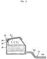
- Figure 2 is a sectional view of a water tank of the grill unit of the present invention with a cover being closed;
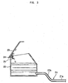
- Figure 3 is a sectional view of the water tank of the grill unit of the present invention with the cover being opened; and
- Figure 4 is a perspective view showing the construction of the water tank and the cover of the grill unit of the present invention.
- As shown in Figure 1, a cooking apparatus with a grill unit according to the present invention includes a cabinet 10 formed in a box shape, and a
grill unit 20 mounted on a top of the cabinet 10 to grill food put on thegrill unit 20. Further, the cooking apparatus includes a plurality ofheaters 11 mounted in the cabinet 10 to heat food put on thegrill unit 20, aheat reflecting member 30 that guides the heat from theheaters 11 to the food on thegrill unit 20 and collects oil dripping from the food, and acover member 40 that covers the upper portion of thegrill unit 20 and has a plurality ofholes - The cabinet 10 has an
opening 12 formed in the top thereof to allow heat generated by theheaters 11 mounted in the cabinet 10 to be transferred to thegrill unit 20.Grill seats 13, each with a predetermined area, are formed on both sides of the top surface of the cabinet 10 around the opening 12 to allow thegrill unit 20 to be seated thereon. Further, atimer switch 14 and apower switch 15 are provided at a certain portion of a top surface of the cabinet 10 to control the heating time and the heating temperature of theheaters 11, respectively. Anopening 16 is formed in a lower portion of the front of the cabinet 10 so that theheat reflecting member 30 may be moved into and out of the cabinet 10 through theopening 16, similar to the operation of a drawer. - The
heaters 11 are set within both sides of the cabinet 10, that is, below thegrill seats 13, to heat food put on thegrill unit 20, and are inclined at a predetermined angle such that heating surfaces of theheaters 11 face the opening 12 formed in the top of the cabinet 10. Theheaters 11 each include a ceramic member in which heating elements are encapsulated to generate infrared rays with a high temperature. However, theheaters 11 may be implemented as gas heaters using gas, or as trays for holding charcoal. - The
heat reflecting member 30 is constructed such that its axial center portion is projected upward to form a hill shape with a triangular cross-section, and both projected surfaces form reflectingsurfaces 31 to allow heat generated by theheaters 11 to be reflected to thegrill unit 20 arranged above theheaters 11. Further,recesses 32 are formed at bottoms of both projected surfaces to collect oil dripping from food put on thegrill unit 20. Further, although not shown in Figure 1, a predetermined amount of water is contained in theheat reflecting member 30 to prevent the temperatures of therecesses 32 and thereflecting surfaces 31 from increasing excessively, thus preventing oil collected in therecesses 32 from burning or adhering to therecesses 32. - The
grill unit 20 includes a plurality ofgrill pipes 21 arranged in parallel with each other while being spaced apart from each other,water tanks 22 connected to both side ends of thegrill pipes 21 to supply water into thegrill pipes 21 and provided with bottom surfaces seated on thegrill seats 13 of the top surface of the cabinet 10, and covers 23 to selectively open and close upper portions of thewater tanks 22. - As shown in Figure 2, each of the
grill pipes 21 is provided with a horizontally extendedpart 21a on which food is placed. The horizontally extendedpart 21a is bent to be positioned lower than both side ends of each of thegrill pipes 21 connected to thewater tanks 22 so that the food is positioned near theheaters 11 arranged below the food. That is, thegrill pipe 21 is provided with twoinclined parts 21b downwardly bent at a predetermined angle and extended from end parts connected to thewater tanks 22. Each of thegrill pipes 21 is bent to be horizontally extended between theinclined parts 21b, so that the horizontally extendedpart 21a on which the food is placed is lower than thewater tanks 20. - The above-described construction of the
grill unit 20 prevents thegrill pipes 21 from overheating by allowing water to flow into thegrill pipes 21 from thewater tanks 22, even though thegrill pipes 21 are heated by heat transferred from theheaters 11 arranged below thegrill unit 20 when the user grills food, thereby preventing the part of food in contact with thegrill pipes 21 from burning. - As shown in Figures 2 and 4, one side of the
cover 23 of thewater tank 22 hingedly connects to the upper portion of thewater tank 22 through ahinge pin 24 so that thecover 23 rotatably opens and closes. Further, aguide member 25 attached to the inner surface of thecover 23 guides water condensed from water vapor formed on the inner surface of thecover 23 into thewater tank 22. Theguide member 25 extends in the longitudinal direction of thecover 23 and bends a predetermined distance to face an inside of thewater tank 22, with one end thereof being connected to the inner surface of thecover 23. - Further, as shown in Figure 2, the
cover 23 is sloped a predetermined angle θ when closed to allow condensed water formed on the inner surface of thecover 23 to flow down. Theguide member 25 is attached to the lower portion of the inner surface of thecover 23. In one instance, thecover 23 is downwardly sloped toward the hingedly connected part so that the condensed water formed on the inner surface of thecover 23 flows down to the hingedly connected part of thecover 23. Theguide member 25 is provided on a lower portion of the inner surface of thecover 23 near the hingedly connected part. - As shown in Figure 2, condensed water formed on the inner surface of the
cover 23 spontaneously flows to theguide member 25 along the inner surface of theinclined cover 23 when cooking, and the condensed water falls down into thewater tank 22 by theguide member 25, thus preventing the condensed water formed on thecover 23 from flowing out of thewater tank 22. - Further, as shown in Figure 3, condensed water formed on the inner surface of the
cover 23 is guided into thewater tank 22 using theguide member 25, even when a user rotates and opens thecover 23. - As is apparent from the above description, the present invention provides a grill unit and cooking apparatus with the same, in which covers of water tanks of the grill unit are downwardly sloped toward hingedly connected parts, and guide members that guide the flow of condensed water are provided on lower portions of the inner surfaces of the covers near the hingedly connected parts, thus preventing the condensed water on the inner surfaces of the covers from flowing out of the water tanks.
- Although a few preferred embodiments have been shown and described, it will be appreciated by those skilled in the art that various changes and modifications might be made without departing from the scope of the invention, as defined in the appended claims.
Claims (14)
- A grill unit, comprising:a plurality of grill pipes (21);water tanks (22) connected to ends of the grill pipes (21) to supply water into the grill pipes (21); andcovers (23) to selectively open and close upper portions of the water tanks (22);characterised by:guide members (25) respectively extending from inner surfaces of the covers (23) toward insides of the water tanks (22) to guide condensed water formed on the inner surfaces of the covers (23) into the water tanks (22).
- The grill unit according to claim 1, wherein each cover (23) has sides with connecting parts at a back of each side to hingedly connect each cover (23) to upper portions of the water tanks (22), respectively, and each guide member (25) is located at a lower portion of the inner surface of each cover (23), respectively, adjacent to the connecting parts.
- The grill unit according to claim 1 or 2, wherein each grill pipe (21) comprises:two inclined parts (21b) downwardly bent at a predetermined angle and extended from end parts connected to the water tanks (22); anda horizontally extended part (21a) extended between the two inclined parts (21b).
- The grill unit according to claim 1, 2 or 3, wherein the covers (23), when closed, are downwardly sloped toward the guide members (25) to allow condensed water formed on the inner surfaces of the covers (23) to flow down toward the guide members (25).
- The grill unit according to claim 1, 2, 3 or 4, wherein the covers (23) are sloped in any one direction to allow condensed water formed on the inner surfaces of the covers (23) to flow down.
- A cooking apparatus, comprising:a cabinet (10) having at least one heater (11) to heat food; anda grill unit (20) mounted on a top surface of the cabinet (10) to support the food, the grill unit (20) comprising:a plurality of grill pipes (21);water tanks (22) connected to ends of the grill pipes (21) to supply water into the grill pipes (21); andcovers (23) to selectively open and close open upper portions of the water tanks (22);characterised by:guide members (25) respectively extending from inner surfaces of the covers (23) toward insides of the water tanks (22) to guide condensed water formed on the inner surfaces of the covers (23) into the water tanks (22).
- The cooking apparatus according to claim 6, wherein each cover has sides with connecting parts at a back of each side to hingedly connect each cover to upper portions of the water tanks (22), respectively, and each guide member (25) is located at a lower portion of the inner surface of each cover, respectively, adjacent to the connecting.
- The cooking apparatus according to claim 6 or 7, wherein each grill pipe (21) comprises:two inclined parts (21b) downwardly bent at a predetermined angle and extended from end parts connected to the water tanks (22); anda horizontally extended part (21a) extended between the two inclined parts (21b).
- The cooking apparatus according to claim 6, 7 or 8, wherein the covers (23), when closed, are downwardly sloped toward the guide members (25) to allow condensed water formed on the inner surfaces of the covers (23) to flow down toward the guide members (25).
- The cooking apparatus according to claim 6, 7, 8 or 9, wherein the covers (23) are sloped in any one direction to allow condensed water formed on the inner surfaces of the covers (23) to flow down.
- A cover for a water tank of a grill unit (20) of a cooking apparatus, the water tank being connected to grill pipes (21) to supply water into the grill pipes (21);
characterised by:connecting parts at backs of respective sides of the cover to hingedly connect the cover to an upper portion of the water tank, the connection parts allowing the cover to be rotatably opened and closed; anda guide member (25) connected to a lower portion of the inner surface of the cover and extending from the inner surface of the cover a predetermined distance toward the inside of the water tank to guide condensed water formed on the inner surface of the cover into the water tank. - The cover of claim 11, wherein the guide member (25) extends along a length of the cover and is positioned adjacent to the connecting parts.
- The cover of claim 11 or 12, wherein the cover, when closed over the water tank, slopes downward from a front of the water tank connected to the grill pipes (21) to a back of the water tank to allow the condensed water to flow down the inner surface of the cover toward the guide member (25) and flows down the guide member (25) into the water tank, thereby preventing the condensed water from flowing out of the water tank.
- The cover of claim 11, 12 or 13, wherein when the cover is opened, the condensed water flows down the inner surface of the cover toward the guide member (25) and flows down the guide member (25) into the water tank, thereby preventing the condensed water from flowing out of the water tank.
Applications Claiming Priority (2)
| Application Number | Priority Date | Filing Date | Title |
|---|---|---|---|
| KR1020030007564A KR20040071024A (en) | 2003-02-06 | 2003-02-06 | Grill and cooking unit with the same |
| KR2003007564 | 2003-02-06 |
Publications (2)
| Publication Number | Publication Date |
|---|---|
| EP1444938A1 EP1444938A1 (en) | 2004-08-11 |
| EP1444938B1 true EP1444938B1 (en) | 2006-04-19 |
Family
ID=36314076
Family Applications (1)
| Application Number | Title | Priority Date | Filing Date |
|---|---|---|---|
| EP03257377A Expired - Fee Related EP1444938B1 (en) | 2003-02-06 | 2003-11-21 | Grill unit and cooking apparatus with the same |
Country Status (6)
| Country | Link |
|---|---|
| US (1) | US6959704B2 (en) |
| EP (1) | EP1444938B1 (en) |
| JP (1) | JP2004237079A (en) |
| KR (1) | KR20040071024A (en) |
| CN (1) | CN1248638C (en) |
| DE (1) | DE60304670T2 (en) |
Families Citing this family (7)
| Publication number | Priority date | Publication date | Assignee | Title |
|---|---|---|---|---|
| KR20040071021A (en) * | 2003-02-06 | 2004-08-11 | 삼성전자주식회사 | Grill and cooking unit with the same |
| KR100881911B1 (en) | 2008-03-24 | 2009-02-06 | 이인재 | Water cooled grill |
| US20100000511A1 (en) * | 2008-07-07 | 2010-01-07 | Athanasios Koropoulis | Barbecue grilling grate assembly |
| US11006782B2 (en) | 2013-09-24 | 2021-05-18 | Koninklijke Philips N.V. | Radiation grill |
| KR102297342B1 (en) * | 2017-08-16 | 2021-09-01 | 엘지전자 주식회사 | Heating device and cooking appliance |
| CN111839235B (en) * | 2019-04-30 | 2022-10-04 | 广东美的厨房电器制造有限公司 | Door body subassembly and domestic appliance |
| CN113995216A (en) * | 2020-07-28 | 2022-02-01 | 台山长江塑料制品有限公司 | Can collect disposable cutlery box of triangle-shaped of comdenstion water |
Family Cites Families (27)
| Publication number | Priority date | Publication date | Assignee | Title |
|---|---|---|---|---|
| US1330209A (en) * | 1920-02-10 | Xcooxing | ||
| US1939715A (en) * | 1932-05-26 | 1933-12-19 | Oscar H Pieper | Sterilizer |
| US2590942A (en) * | 1948-09-13 | 1952-04-01 | Cornelius Carroll | Cooking stove |
| US2664221A (en) * | 1949-09-14 | 1953-12-29 | Spred All Inc | Lid construction for material spreaders |
| US2715898A (en) * | 1951-09-27 | 1955-08-23 | Gen Electric | Food warming and conditioning device |
| US3154004A (en) | 1961-06-19 | 1964-10-27 | Knapp Monarch Co | Oven toaster |
| US3152242A (en) | 1963-02-25 | 1964-10-06 | Gen Electric | Cooking appliance or toaster |
| US3371659A (en) | 1966-09-14 | 1968-03-05 | Tom S. Paspalas | Throw-away portable stove |
| US3609297A (en) * | 1969-02-24 | 1971-09-28 | Petros D Christopoulos | Moisture warming device |
| US3780642A (en) * | 1971-10-29 | 1973-12-25 | E Bay | Casserole |
| US3754116A (en) * | 1972-03-15 | 1973-08-21 | Sperry Rand Corp | Hair roller appliance |
| US4373511A (en) * | 1980-05-27 | 1983-02-15 | Miles Derek A | Cooking vessel |
| US4508024A (en) | 1984-04-09 | 1985-04-02 | Perkins Gary M | Indoor-outdoor convertible cooker |
| US4893609A (en) | 1986-09-26 | 1990-01-16 | Teledyne Industries, Inc. | Wind-resistant outdoor heating appliance |
| FR2670274B1 (en) | 1990-12-07 | 1996-04-26 | Seb Sa | ELECTRIC COOKING APPARATUS WITH REFLECTOR. |
| US5189945A (en) * | 1991-11-18 | 1993-03-02 | Hennick Donald C | Water cooled barbecue grill |
| US5387781A (en) * | 1992-11-09 | 1995-02-07 | Berkoff; William | Vented food cooking system for microwave ovens |
| GB9325566D0 (en) | 1993-12-14 | 1994-02-16 | Makris Andreas | Horizontal gas grill |
| FR2724833B1 (en) | 1994-09-26 | 1997-01-17 | Seb Sa | COOKING APPARATUS AND CATALYST FORMING DEVICE PROVIDED WITH SUCH AN APPARATUS |
| JP2786406B2 (en) * | 1995-01-30 | 1998-08-13 | 松下冷機株式会社 | Water cooler |
| FR2732880B1 (en) * | 1995-04-11 | 1997-06-13 | Seb Sa | FOOD CONTAINER WITH LID HAVING A POURING FUNCTION |
| US5535733A (en) | 1995-05-12 | 1996-07-16 | Pyromid, Inc. | Heat radiator for outdoor cooking unit |
| US5613451A (en) * | 1995-05-15 | 1997-03-25 | Illinois Tool Works Inc. | Removable hopper cover |
| JPH10293211A (en) * | 1997-04-17 | 1998-11-04 | Nitto Denko Corp | Polarizing element, illuminator and liquid crystal display device |
| US6125838A (en) | 1998-12-22 | 2000-10-03 | Grills And Gadgets, Inc. | Gas grill with internal baffles for use in high wind conditions |
| FR2811875B1 (en) * | 2000-07-19 | 2003-06-20 | Staub | COOKER COVER OR THE LIKE |
| US6293276B1 (en) | 2000-07-31 | 2001-09-25 | Andrea Gonzella Owens | Cook grill top lid |
-
2003
- 2003-02-06 KR KR1020030007564A patent/KR20040071024A/en not_active Application Discontinuation
- 2003-11-03 CN CNB200310104783XA patent/CN1248638C/en not_active Expired - Fee Related
- 2003-11-05 JP JP2003376169A patent/JP2004237079A/en active Pending
- 2003-11-14 US US10/706,926 patent/US6959704B2/en not_active Expired - Fee Related
- 2003-11-21 EP EP03257377A patent/EP1444938B1/en not_active Expired - Fee Related
- 2003-11-21 DE DE60304670T patent/DE60304670T2/en not_active Expired - Lifetime
Also Published As
| Publication number | Publication date |
|---|---|
| DE60304670D1 (en) | 2006-05-24 |
| US20040154605A1 (en) | 2004-08-12 |
| DE60304670T2 (en) | 2007-04-12 |
| JP2004237079A (en) | 2004-08-26 |
| KR20040071024A (en) | 2004-08-11 |
| CN1518936A (en) | 2004-08-11 |
| CN1248638C (en) | 2006-04-05 |
| EP1444938A1 (en) | 2004-08-11 |
| US6959704B2 (en) | 2005-11-01 |
Similar Documents
| Publication | Publication Date | Title |
|---|---|---|
| US5189945A (en) | Water cooled barbecue grill | |
| US8261732B2 (en) | Cooking grill | |
| US7905225B2 (en) | Cooking grill | |
| US5211105A (en) | Smokeless and scorchless grill pan | |
| EP1417917B1 (en) | Cooking apparatus | |
| EP1407699B1 (en) | Grilling apparatus | |
| EP0818168B1 (en) | Cooking implement comprising a cooking plate and a cooking vessel | |
| EP1444937B1 (en) | Grill unit and cooking apparatus with the same | |
| EP1444938B1 (en) | Grill unit and cooking apparatus with the same | |
| KR20040055591A (en) | Electric fryer with a device for the maintenance with the heat of fried food | |
| US6213004B1 (en) | Portable broiling device | |
| EP1417916B1 (en) | Cooking apparatus | |
| EP1417918B1 (en) | Cooking apparatus | |
| KR200459644Y1 (en) | meat roaster | |
| KR200422827Y1 (en) | Roaster which has a water - cooling system | |
| KR200487893Y1 (en) | Roasting apparatus for grilling meat | |
| EP1444934B1 (en) | Grill unit and cooking apparatus with the same | |
| EP1680994B1 (en) | Cooking apparatus | |
| KR200395681Y1 (en) | Electric Device for Barbecue | |
| KR200196698Y1 (en) | Charcoal roaster | |
| KR101669768B1 (en) | Automatic roast machine for the skewered barbecue with smoke prevention and versatile grill funtion | |
| JP4001030B2 (en) | Cooker | |
| CN2317784Y (en) | Improved roasting device | |
| KR200372896Y1 (en) | Drawer mode chicken roast machine using charcoal panel | |
| KR200248988Y1 (en) | a grill of gas range |
Legal Events
| Date | Code | Title | Description |
|---|---|---|---|
| PUAI | Public reference made under article 153(3) epc to a published international application that has entered the european phase |
Free format text: ORIGINAL CODE: 0009012 |
|
| 17P | Request for examination filed |
Effective date: 20031210 |
|
| AK | Designated contracting states |
Kind code of ref document: A1 Designated state(s): AT BE BG CH CY CZ DE DK EE ES FI FR GB GR HU IE IT LI LU MC NL PT RO SE SI SK TR |
|
| AX | Request for extension of the european patent |
Extension state: AL LT LV MK |
|
| 17Q | First examination report despatched |
Effective date: 20041006 |
|
| AKX | Designation fees paid |
Designated state(s): DE FR GB |
|
| RBV | Designated contracting states (corrected) |
Designated state(s): DE FR GB |
|
| GRAP | Despatch of communication of intention to grant a patent |
Free format text: ORIGINAL CODE: EPIDOSNIGR1 |
|
| GRAS | Grant fee paid |
Free format text: ORIGINAL CODE: EPIDOSNIGR3 |
|
| GRAA | (expected) grant |
Free format text: ORIGINAL CODE: 0009210 |
|
| AK | Designated contracting states |
Kind code of ref document: B1 Designated state(s): DE FR GB |
|
| REG | Reference to a national code |
Ref country code: GB Ref legal event code: FG4D |
|
| RIN1 | Information on inventor provided before grant (corrected) |
Inventor name: YEO, JOO-YEONG Inventor name: HAHM, KYUNG-HEE Inventor name: JANG, SEONG-DEOG Inventor name: KIM, CHUL Inventor name: HAN, DAE-SUNG Inventor name: HAN, YONG-WOON Inventor name: KANG, HAN-SEONG |
|
| REF | Corresponds to: |
Ref document number: 60304670 Country of ref document: DE Date of ref document: 20060524 Kind code of ref document: P |
|
| ET | Fr: translation filed | ||
| PLBE | No opposition filed within time limit |
Free format text: ORIGINAL CODE: 0009261 |
|
| STAA | Information on the status of an ep patent application or granted ep patent |
Free format text: STATUS: NO OPPOSITION FILED WITHIN TIME LIMIT |
|
| 26N | No opposition filed |
Effective date: 20070122 |
|
| PGFP | Annual fee paid to national office [announced via postgrant information from national office to epo] |
Ref country code: FR Payment date: 20101123 Year of fee payment: 8 |
|
| PGFP | Annual fee paid to national office [announced via postgrant information from national office to epo] |
Ref country code: DE Payment date: 20101117 Year of fee payment: 8 |
|
| PGFP | Annual fee paid to national office [announced via postgrant information from national office to epo] |
Ref country code: GB Payment date: 20101117 Year of fee payment: 8 |
|
| GBPC | Gb: european patent ceased through non-payment of renewal fee |
Effective date: 20111121 |
|
| REG | Reference to a national code |
Ref country code: FR Ref legal event code: ST Effective date: 20120731 |
|
| REG | Reference to a national code |
Ref country code: DE Ref legal event code: R119 Ref document number: 60304670 Country of ref document: DE Effective date: 20120601 |
|
| PG25 | Lapsed in a contracting state [announced via postgrant information from national office to epo] |
Ref country code: GB Free format text: LAPSE BECAUSE OF NON-PAYMENT OF DUE FEES Effective date: 20111121 |
|
| PG25 | Lapsed in a contracting state [announced via postgrant information from national office to epo] |
Ref country code: FR Free format text: LAPSE BECAUSE OF NON-PAYMENT OF DUE FEES Effective date: 20111130 |
|
| PG25 | Lapsed in a contracting state [announced via postgrant information from national office to epo] |
Ref country code: DE Free format text: LAPSE BECAUSE OF NON-PAYMENT OF DUE FEES Effective date: 20120601 |