EP1444149B1 - Organe de distribution de produit fluide - Google Patents
Organe de distribution de produit fluide Download PDFInfo
- Publication number
- EP1444149B1 EP1444149B1 EP02785591A EP02785591A EP1444149B1 EP 1444149 B1 EP1444149 B1 EP 1444149B1 EP 02785591 A EP02785591 A EP 02785591A EP 02785591 A EP02785591 A EP 02785591A EP 1444149 B1 EP1444149 B1 EP 1444149B1
- Authority
- EP
- European Patent Office
- Prior art keywords
- dispenser
- unit
- identification unit
- dispensing member
- fluid
- Prior art date
- Legal status (The legal status is an assumption and is not a legal conclusion. Google has not performed a legal analysis and makes no representation as to the accuracy of the status listed.)
- Expired - Lifetime
Links
- 239000012530 fluid Substances 0.000 title claims description 8
- 238000009826 distribution Methods 0.000 description 6
- 239000000463 material Substances 0.000 description 5
- 230000005540 biological transmission Effects 0.000 description 3
- 239000000470 constituent Substances 0.000 description 3
- 239000002537 cosmetic Substances 0.000 description 2
- 238000002788 crimping Methods 0.000 description 2
- 238000004519 manufacturing process Methods 0.000 description 2
- 239000002184 metal Substances 0.000 description 2
- 238000000034 method Methods 0.000 description 2
- 239000011347 resin Substances 0.000 description 2
- 229920005989 resin Polymers 0.000 description 2
- 235000008429 bread Nutrition 0.000 description 1
- 239000002775 capsule Substances 0.000 description 1
- 230000000694 effects Effects 0.000 description 1
- 238000005538 encapsulation Methods 0.000 description 1
- 239000006200 vaporizer Substances 0.000 description 1
Images

Classifications
-
- B—PERFORMING OPERATIONS; TRANSPORTING
- B65—CONVEYING; PACKING; STORING; HANDLING THIN OR FILAMENTARY MATERIAL
- B65D—CONTAINERS FOR STORAGE OR TRANSPORT OF ARTICLES OR MATERIALS, e.g. BAGS, BARRELS, BOTTLES, BOXES, CANS, CARTONS, CRATES, DRUMS, JARS, TANKS, HOPPERS, FORWARDING CONTAINERS; ACCESSORIES, CLOSURES, OR FITTINGS THEREFOR; PACKAGING ELEMENTS; PACKAGES
- B65D83/00—Containers or packages with special means for dispensing contents
- B65D83/14—Containers for dispensing liquid or semi-liquid contents by internal gaseous pressure, i.e. aerosol containers comprising propellant
- B65D83/75—Aerosol containers not provided for in groups B65D83/16 - B65D83/74
-
- B—PERFORMING OPERATIONS; TRANSPORTING
- B05—SPRAYING OR ATOMISING IN GENERAL; APPLYING FLUENT MATERIALS TO SURFACES, IN GENERAL
- B05B—SPRAYING APPARATUS; ATOMISING APPARATUS; NOZZLES
- B05B11/00—Single-unit hand-held apparatus in which flow of contents is produced by the muscular force of the operator at the moment of use
- B05B11/0005—Components or details
-
- B—PERFORMING OPERATIONS; TRANSPORTING
- B05—SPRAYING OR ATOMISING IN GENERAL; APPLYING FLUENT MATERIALS TO SURFACES, IN GENERAL
- B05B—SPRAYING APPARATUS; ATOMISING APPARATUS; NOZZLES
- B05B15/00—Details of spraying plant or spraying apparatus not otherwise provided for; Accessories
-
- B—PERFORMING OPERATIONS; TRANSPORTING
- B65—CONVEYING; PACKING; STORING; HANDLING THIN OR FILAMENTARY MATERIAL
- B65D—CONTAINERS FOR STORAGE OR TRANSPORT OF ARTICLES OR MATERIALS, e.g. BAGS, BARRELS, BOTTLES, BOXES, CANS, CARTONS, CRATES, DRUMS, JARS, TANKS, HOPPERS, FORWARDING CONTAINERS; ACCESSORIES, CLOSURES, OR FITTINGS THEREFOR; PACKAGING ELEMENTS; PACKAGES
- B65D2203/00—Decoration means, markings, information elements, contents indicators
- B65D2203/10—Transponders
Definitions
- the present invention relates to a fluid dispenser, such as a vaporizer, comprising a body defining an inlet duct, an actuator rod displaceable in the body, an actuating member coupled to the actuating rod, and fixing means for fixing the body in a container opening containing fluid.
- a fluid dispenser such as a vaporizer
- This is a quite conventional or conventional design for a pump or a valve used in the field of perfumery, cosmetics or even pharmacy to dispense fluid products contained in containers such as vials , bottles, etc.
- the present invention relates to the authentication capability as well as the traceability of the dispensing member or more generally of the dispenser using such a dispensing member. It is indeed important to be able to identify without doubt the origin of the distribution unit in order to quickly and easily distinguish between an authentic and an imitation or counterfeit. More particularly for traceability, it is important to be able to follow the path or route of the distribution unit from manufacture to sale or sale.
- the object of the present invention is to overcome this aforementioned drawback of the prior art by defining a new, virtually tamper-proof identification means for a dispensing member or dispenser using such a member.
- the present invention provides a dispenser according to claim 1.
- the identification unit comprises an integrated circuit and an antenna capable of transmitting signals bearing information.
- the signals may for example be of the radiofrequency type.
- the identification unit is therefore able to deliver information in the form of a signal in response to an information request transmission signal received by the antenna of the unit.
- the identification unit is embedded in a support integral with the body.
- the support forms a ring engaged around the body.
- identification is embedded in the actuating member.
- the actuating member is a pusher mounted on the actuating rod.
- the identification unit is embedded in the fixing means.
- the identification unit may be attached to the constituent components of the dispenser member, or alternatively it may be encapsulated or embedded in the mass forming the component.
- the dispensing member 1 shown in the figures may be a pump or a valve.
- the dispensing member 1 comprises all the components necessary for its mounting on a container 2.
- the container 2 comprises a neck 21 defining an opening 20 through which the interior of the container 2 communicates with the outside.
- the dispensing member 1 comprises a body 10 defining an inlet sleeve 11 at which can be connected a dip tube 14 which extends inside the container 2 to the level of its bottom.
- the body 10 comprises at its end opposite the inlet sleeve 11 a flange 12 which projects outwardly.
- the dispensing member also comprises an actuating rod 13 which is mounted translatable to the interior of the body 10. This actuating rod 13 drives an element (not visible) which can be a piston in the case of a piston. pump or a valve in the case of a valve. But this is not critical for the present invention.
- An actuating member 15 in the form of a pusher is mounted on the upper end of the actuating rod 13.
- the pusher 15 forms the dispensing orifice 16, for example in the form of a jet.
- the operation of such a dispensing member is very simple and well known: simply press the pusher 15 to move the actuating rod 13 in the body 10 which has the effect of distributing a quantity of fluid dosed or not through the actuating rod 13 to the dispensing orifice 16. All this is quite conventional for a pump or a valve in the field of cosmetics, perfumery or pharmacy.
- fixing means 17 which are here in the form of a crimping cup.
- This cup 17 forms a receiving housing for the flange 12 of the body 10 and also forms a crimping around the neck 21.
- the fastening means can also be presented under the form of a ring or a turret for example made of plastic material which engages inside or outside the neck and which also forms a receiving housing for the flange 12 of the body 10. Again, the particular form of the fastening means is not critical for the present invention.
- the fixing means 17 advantageously comprise a neck seal 18 intended to be compressed on the upper end of the neck 21. This is a description of a pump or of a valve quite classic.
- the dispenser member further comprises an identification unit capable of delivering one or more information relating to the dispenser member.
- the information delivered by the identification unit may be quite different in nature: it may for example be information concerning characteristics specific to the dispenser, its date and place of manufacture , destination, date of dispatch, date of receipt, place of receipt, etc.
- the information is transmitted from the radio frequency identification unit.
- the identification unit comprises an integrated circuit 301 associated with an antenna 302, all embedded or encapsulated in a mass of resin 303 or any other suitable material. This is visible on the figure 5 .
- This is an example of a known embodiment for a radiofrequency type identification unit.
- the integrated circuit stores the information coming from an information transmission unit that is received by the antenna 302.
- a transmission unit is also used. which sends an information request signal received by the antenna 302 and in response to this information request signal, the integrated circuit 301 will restore the stored information through the antenna 302.
- radiofrequency identification unit is of course only an exemplary embodiment, and it can be understood that it is possible to use any type of identification unit that operates with another technique for transmitting information.
- the inlet sleeve 11 is provided with a ring 31 which serves as a support for the identification unit 3.
- the ring 31 can be simply force-fitted on the inlet sleeve 11 until in abutment.
- the identification unit 3 may simply be housed or placed in the support ring 31, or alternatively, the identification unit 3 may be encapsulated or embedded in the constituent mass of the support ring 31. This is a preferred embodiment because the identification unit is not surrounded by metal, which could interfere with the operation of the antenna. In addition, the identification unit is protected inside the tank. To remove it, it would disassemble or destroy the dispenser.
- the identification unit 3 is housed in the pusher 15 which forms a housing adapted to receive the identification unit 3. It can however be imagined that the identification unit 3 is embedded or encapsulated in the constituent material, in this case the plastic material, of the pusher 15. In this case, the resin bread 303 is literally replaced by the plastic material constituting the pusher 15. In the case where the pusher is dressed with an overcap, for example metal example, the identification unit can be placed and maintained on the over-capsule.
- the identification unit 3 is supported by a ring 31 engaged around the body 10 just in the opening 20 under the seal 18. This is an alternative embodiment of the figure 1 , and the identification unit 3 can be simply placed or still embedded in the support ring 31.
- the identification unit 3 is mounted on the neck seal 18 which forms a receiving recess for the identification unit 3 for this purpose.
- the identification unit can be placed in the body 10 or even in the wall constituting the body 10 by an encapsulation process or flooding.
- the identification unit 3 is truly an integral part of the dispenser member so that it is inseparable.
Landscapes
- Chemical & Material Sciences (AREA)
- Dispersion Chemistry (AREA)
- Engineering & Computer Science (AREA)
- Mechanical Engineering (AREA)
- Containers And Packaging Bodies Having A Special Means To Remove Contents (AREA)
- Closures For Containers (AREA)
- Details Of Rigid Or Semi-Rigid Containers (AREA)
- Coating Apparatus (AREA)
Description
- La présente invention concerne un distributeur de produit fluide, tel qu'un vaporisateur, comprenant un corps définissant un conduit d'entrée, une tige d'actionnement déplaçable dans le corps, un organe d'actionnement couplé à la tige d'actionnement, et des moyens de fixation pour fixer le corps dans une ouverture de récipient contenant du produit fluide. Il s'agit là d'une conception tout à fait classique ou conventionnelle pour une pompe ou une valve utilisée dans le domaine de la parfumerie, de la cosmétique ou encore de la pharmacie pour distribuer des produits fluides contenus dans des récipients tels que des flacons, bouteilles, etc.
- Plus particulièrement, la présente invention concerne la capacité d'authentification ainsi que la traçabilité de l'organe de distribution ou plus généralement du distributeur utilisant un tel organe de distribution. Il est en effet important de pouvoir identifier sans doute possible l'origine de l'organe de distribution afin de pouvoir distinguer rapidement et facilement entre un authentique et une imitation ou contrefaçon. Plus particulièrement pour la traçabilité, il est important de pouvoir suivre le cheminement ou le parcours de l'organe de distribution depuis sa fabrication jusqu'à sa vente ou sa mise en vente.
- Il est déjà connu depuis longtemps d'utiliser des marques ou des signes distinctifs apposés ou intégrés dans le distributeur ou l'organe de distribution de manière à pouvoir identifier visuellement l'origine du produit. Toutefois, il est très facile pour un contrefacteur d'imiter cette marque ou ce signe distinctif et de l'apposer sur des distributeurs contrefaisants.
- La présente invention a pour but de remédier à cet inconvénient précité de l'art antérieur en définissant un nouveau moyen d'identification pratiquement infalsifiable d'un organe de distribution ou d'un distributeur utilisant un tel organe.
- Pour atteindre ce but, la présente invention prévoit un distributeur selon la revendication 1.
- L'unité d'identification comprend un circuit intégré et une antenne apte à émettre des signaux portant une information. Les signaux peuvent par exemple être du type radiofréquence. L'unité d'identification est donc apte à délivrer une information sous la forme d'un signal en réponse à un signal d'émission de demande d'information reçue par l'antenne de l'unité.
- Selon une forme de réalisation de l'invention, l'unité d'identification est embarquée dans un support solidaire du corps. Avantageusement, le support forme une bague en prise autour du corps.
- Selon un autre mode de réalisation non revendiqué, d'identification est embarquée dans l'organe d'actionnement. Avantageusement, l'organe d'actionnement est un poussoir monté sur la tige d'actionnement.
- Selon un autre mode de réalisation non revendiqué, l'unité d'identification est embarquée dans les moyens de fixation.
- L'unité d'identification peut être fixée aux composants constitutifs de l'organe de distribution, ou en variante elle peut être encapsulée ou noyée dans la masse formant le composant.
- L'invention sera maintenant plus amplement décrite en référence aux dessins joints donnant à titre d'exemples non limitatifs plusieurs modes de réalisation de l'invention.
- Sur les figures :
- la
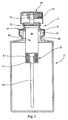
figure 1 est une vue partiellement en coupe transversale verticale à travers un distributeur de produit fluide pourvu d'un organe de distribution selon une première forme de réalisation de l'invention, - la
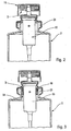
figure 2 est une vue tronquée similaire à lafigure 1 montrant une seconde forme de réalisation de l'organe de distribution non revendiquée, - la
figure 3 est une vue similaire à lafigure 2 montrant une troisième forme de réalisation de l'organe de distribution selon l'invention, - la
figure 4 est une vue largement agrandie d'une partie d'un distributeur utilisant un organe de distribution selon une quatrième forme de réalisation non revendiquée, et - la
figure 5 est une vue schématique montrant un exemple de réalisation d'une unité d'identification radiofréquence. - La présente invention s'applique à tous les organes de distribution tels que les pompes ou les valves. Par conséquent, l'organe de distribution 1 représenté sur les figures peut être au choix une pompe ou une valve. L'organe de distribution 1 comprend tous les composants nécessaires à son montage sur un récipient 2. Pour ce faire, le récipient 2 comprend un col 21 définissant une ouverture 20 par laquelle l'intérieur du récipient 2 communique avec l'extérieur.
- L'organe de distribution 1 comprend un corps 10 définissant un manchon d'entrée 11 au niveau duquel peut être raccordé un tube-plongeur 14 qui s'étend à l'intérieur du récipient 2 jusqu'au niveau de son fond. Le corps 10 comprend à son extrémité opposée au manchon d'entrée 11 une collerette 12 qui fait saillie vers l'extérieur. L'organe de distribution comprend également une tige d'actionnement 13 qui est montée déplaçable translativement à l'intérieur du corps 10. Cette tige d'actionnement 13 entraîne un élément (non visible) qui peut être un piston dans le cas d'une pompe ou une soupape dans le cas d'une valve. Mais ceci n'est pas critique pour la présente invention. Un organe d'actionnement 15 sous la forme d'un poussoir est monté sur l'extrémité supérieure de la tige d'actionnement 13. Dans l'exemple représenté, le poussoir 15 forme l'orifice de distribution 16, par exemple sous la forme d'un gicleur. Le fonctionnement d'un tel organe de distribution est très simple et bien connu : il suffit d'appuyer sur le poussoir 15 pour déplacer la tige d'actionnement 13 dans le corps 10 ce qui a pour effet de distribuer une quantité de produit fluide dosée ou non à travers la tige d'actionnement 13 jusqu'à l'orifice de distribution 16. Tout ceci est tout à fait classique pour une pompe ou une valve dans le domaine de la cosmétique, de la parfumerie ou encore de la pharmacie.
- Pour la fixation du corps 10 dans l'ouverture 20 du récipient 2, il est prévu des moyens de fixation 17 qui se présentent ici sous la forme d'une coupelle à sertir. Cette coupelle 17 forme un logement de réception pour la collerette 12 du corps 10 et forme également un sertissage autour du col 21. Il s'agit là d'un exemple de réalisation non limitatif, car les moyens de fixation peuvent également se présenter sous la forme d'une bague ou d'une tourette par exemple réalisée en matière plastique qui vient en prise à l'intérieur ou à l'extérieur du col et qui forme également un logement de réception pour la collerette 12 du corps 10. Là encore, la forme particulière des moyens de fixation n'est pas critique pour la présente invention.
- Pour réaliser une fixation étanche dans l'ouverture 20, les moyens de fixation 17 comprennent avantageusement un joint de col 18 destiné à être comprimé sur l'extrémité supérieure du col 21. Il s'agit là d'une description d'une pompe ou d'une valve tout à fait classique.
- Selon l'invention, l'organe de distribution comprend en outre une unité d'identification apte à délivrer une ou des informations relatives à l'organe de distribution. Là où les informations délivrées par l'unité d'identification peuvent être de nature tout à fait diverse : il peut par exemple s'agir d'informations concernant des caractéristiques propres à l'organe de distribution, à sa date et son lieu de fabrication, sa destination, sa date d'envoi, sa date de réception, son lieu de réception, etc. Les informations sont transmises depuis l'unité d'identification par radiofréquence. Dans ce cas, l'unité d'identification comprend un circuit intégré 301 associé à une antenne 302, le tout noyé ou encapsulé dans une masse de résine 303 ou tout autre matériau approprié. Ceci est visible sur la
figure 5 . Il s'agit là d'un exemple de réalisation connu pour une unité d'identification du type radiofréquence. Le circuit intégré stocke les informations provenant d'une unité d'émission d'information qui sont reçues par l'antenne 302. Pour restituer ou délivrer les informations stockées par le circuit intégré 301, on se sert également d'une unité d'émission qui envoie un signal de demande d'information reçue par l'antenne 302 et en réponse à ce signal de demande d'information, le circuit intégré 301 va restituer les informations stockées par l'intermédiaire de l'antenne 302. - L'utilisation d'une telle unité d'identification radiofréquence n'est bien entendu qu'un exemple de réalisation, et on peut comprendre qu'il est possible d'utiliser n'importe quel type d'unité d'identification qui fonctionne avec une autre technique de transmission de l'information.
- En se référant maintenant à la
figure 1 , on voit que le manchon d'entrée 11 est pourvu d'une bague 31 qui sert de support pour l'unité d'identification 3. La bague 31 peut être simplement emmanchée en force sur le manchon d'entrée 11 jusqu'à venir en butée. L'unité d'identification 3 peut être simplement logée ou placée dans la bague de support 31, ou en variante, l'unité d'identification 3 peut être encapsulée ou noyée dans la masse constitutive de la bague de support 31. Il s'agit là d'une forme de réalisation préférée, car l'unité d'identification n'est pas entourée par du métal, qui pourrait perturber le fonctionnement de l'antenne. De plus, l'unité d'identification est protégée à l'intérieur du réservoir. Pour la retirer, il faudrait démonter ou détruire le distributeur. - En se référant maintenant à la
figure 2 , on voit que l'unité d'identification 3 est logée dans le poussoir 15 qui forme un logement apte à recevoir l'unité d'identification 3. On peut toutefois imaginer que l'unité d'identification 3 est noyée ou encapsulée dans la matière constitutive, en l'occurrence de la matière plastique, du poussoir 15. Dans ce cas, le pain de résine 303 est littéralement remplacé par la matière plastique constitutive du poussoir 15. Dans le cas où le poussoir est habillé avec une surcapsule, par exemple en métal, l'unité d'identification peut être placée et maintenue sur la surcapsule. - En se référant à la
figure 3 , on voit que l'unité d'identification 3 est supportée par une bague 31 engagée autour du corps 10 juste dans l'ouverture 20 sous le joint 18. Il s'agit là d'une variante de réalisation de lafigure 1 , et l'unité d'identification 3 peut être simplement placée ou encore noyée dans la bague de support 31. - En se référant à la
figure 4 , on voit que l'unité d'identification 3 est montée sur le joint de col 18 qui forme à cet effet un évidement de réception pour l'unité d'identification 3. - On peut bien entendu encore imaginer d'autres emplacements pour une telle unité d'identification 3. On peut par exemple placer l'unité d'identification dans le corps 10 ou même dans la paroi constitutive du corps 10 par un procédé d'encapsulage ou de noyage.
- Avec l'invention, l'unité d'identification 3 fait véritablement partie intégrante de l'organe de distribution de sorte qu'elle en est indissociable.
Claims (5)
- Distributeur de produit fluide comprenant un récipient (2) et un organe de distribution de produit fluide (1) comprenant les composants suivants :- un corps (10) définissant un conduit d'entrée (11),- une tige d'actionnement (13) déplaçable dans le corps,- un organe d'actionnement (15) couplé à la tige d'actionnement, et- des moyens de fixation (17) pour fixer le corps (10) dans une ouverture (20) du récipient (2) contenant du produit fluide,caractérisé en ce que le corps (10) est pourvu d'une unité d'identification (3) apte à stocker et délivrer une information relative à l'organe de distribution, l'unité d'identification (3) comprenant un circuit intégré (301) apte à stocker une information et une antenne (302) apte à émettre des signaux portant cette information, dans lequel l'unité d'identification est situé dans le récipient.
- Distributeur selon la revendication 1, dans lequel l'unité d'identification (3) est embarquée dans un support (31) solidaire du corps (10).
- Distributeur selon la revendication 2, dans lequel le support forme une bague (31) en prise autour du corps (10).
- Distributeur selon l'une quelconque des revendications précédentes, dans lequel l'unité d'identification (3) est fixée au corps.
- Distributeur selon l'une quelconque des revendications précédentes, dans lequel l'unité d'identification (3) est encapsulée ou noyée dans le corps.
Applications Claiming Priority (3)
| Application Number | Priority Date | Filing Date | Title |
|---|---|---|---|
| FR0114724 | 2001-11-09 | ||
| FR0114724A FR2832134B1 (fr) | 2001-11-09 | 2001-11-09 | Organe de distribution de produit fluide et distributeur comprenant un tel organe |
| PCT/FR2002/003799 WO2003039997A1 (fr) | 2001-11-09 | 2002-11-06 | Organe de distribution de produit fluide et distributeur comprenant un tel organe |
Publications (2)
| Publication Number | Publication Date |
|---|---|
| EP1444149A1 EP1444149A1 (fr) | 2004-08-11 |
| EP1444149B1 true EP1444149B1 (fr) | 2009-10-28 |
Family
ID=8869383
Family Applications (1)
| Application Number | Title | Priority Date | Filing Date |
|---|---|---|---|
| EP02785591A Expired - Lifetime EP1444149B1 (fr) | 2001-11-09 | 2002-11-06 | Organe de distribution de produit fluide |
Country Status (8)
| Country | Link |
|---|---|
| EP (1) | EP1444149B1 (fr) |
| JP (1) | JP4452503B2 (fr) |
| CN (1) | CN100377974C (fr) |
| BR (1) | BR0213808B1 (fr) |
| DE (1) | DE60234205D1 (fr) |
| ES (1) | ES2332265T3 (fr) |
| FR (1) | FR2832134B1 (fr) |
| WO (1) | WO2003039997A1 (fr) |
Families Citing this family (15)
| Publication number | Priority date | Publication date | Assignee | Title |
|---|---|---|---|---|
| FR2864035B1 (fr) * | 2003-12-18 | 2006-02-03 | Att Advanced Track & Trace | Pompe comportant une etiquette electronique |
| FR2864040B1 (fr) | 2003-12-19 | 2006-03-31 | Valois Sas | Organe de distribution de produit fluide et distributeur comprenant un tel organe |
| WO2005075088A2 (fr) * | 2004-01-30 | 2005-08-18 | Nordson Corporation | Systeme d'application de materiau a composant ayant des aptitudes a effectuer des operations d'identification sans fil |
| US20050252930A1 (en) * | 2004-05-11 | 2005-11-17 | Contadini Carl D | Dispensing system, a dispenser and a source of material to be used therewith |
| FR2876200B1 (fr) * | 2004-10-01 | 2006-12-29 | Valois Sa Sa | Unite d'identification, organe de distribution pourvu d'une telle unite d'identification et procede de fabrication d'une telle unite d'identification |
| KR101297004B1 (ko) | 2005-04-25 | 2013-08-14 | 도쿄엘렉트론가부시키가이샤 | 비어 있음 검출 능력을 갖는 라이너 기반의 액체 저장 및 분배 시스템 |
| EP2388231B1 (fr) | 2005-06-06 | 2018-09-26 | Entegris, Inc. | Systèmes de stockage et de distribution de combustible et procédés |
| KR101111476B1 (ko) * | 2006-12-21 | 2012-02-22 | 더 프록터 앤드 갬블 캄파니 | 분배 측정 장치 및 분배 측정 방법 |
| FR2911421A1 (fr) * | 2007-01-17 | 2008-07-18 | Valois Sas | Procede de marquage et d'authentification d'un article |
| WO2009013396A1 (fr) * | 2007-07-24 | 2009-01-29 | Devoucoux Sellier | Procede d'identification d'une selle d'equitation |
| GB2452970A (en) * | 2007-09-21 | 2009-03-25 | Reckitt Benckiser | Spraying device and method utilizing reflectance spray head |
| FR2976565B1 (fr) * | 2011-06-14 | 2014-09-05 | Valois Sas | Dispositif de distribution de produit fluide et procede de fabrication d'un tel dispositif. |
| FR3053877B1 (fr) * | 2016-07-12 | 2020-09-18 | Albea Services | Recipient pour un produit cosmetique presentant une periode apres ouverture donnee |
| FR3069465B1 (fr) | 2017-07-25 | 2019-08-09 | Aptar France Sas | Ensemble de distribution de produit fluide |
| CN107572119A (zh) * | 2017-09-30 | 2018-01-12 | 广州市科能化妆品科研有限公司 | 定量出液的化妆品瓶 |
Family Cites Families (4)
| Publication number | Priority date | Publication date | Assignee | Title |
|---|---|---|---|---|
| IT7921338U1 (it) * | 1979-04-12 | 1980-10-12 | Adm Spa | Erogatore con linguetta sigillo di garanzia, applicabile a valvole aerosol |
| JP2000085864A (ja) * | 1998-09-09 | 2000-03-28 | Osaka Ship Building Co Ltd | デリバリーシステム |
| WO2001028887A1 (fr) * | 1999-10-16 | 2001-04-26 | Glaxo Group Limited | Dispositif de logement pour contenant d'aerosol |
| DE20105605U1 (de) * | 2001-03-27 | 2001-06-13 | WGA GmbH, 47441 Moers | Verschluss für ein Behältnis für ein Rückstellmuster |
-
2001
- 2001-11-09 FR FR0114724A patent/FR2832134B1/fr not_active Expired - Fee Related
-
2002
- 2002-11-06 WO PCT/FR2002/003799 patent/WO2003039997A1/fr not_active Ceased
- 2002-11-06 EP EP02785591A patent/EP1444149B1/fr not_active Expired - Lifetime
- 2002-11-06 JP JP2003542054A patent/JP4452503B2/ja not_active Expired - Fee Related
- 2002-11-06 CN CNB028222873A patent/CN100377974C/zh not_active Expired - Lifetime
- 2002-11-06 BR BRPI0213808-5A patent/BR0213808B1/pt not_active IP Right Cessation
- 2002-11-06 ES ES02785591T patent/ES2332265T3/es not_active Expired - Lifetime
- 2002-11-06 DE DE60234205T patent/DE60234205D1/de not_active Expired - Lifetime
Also Published As
| Publication number | Publication date |
|---|---|
| CN100377974C (zh) | 2008-04-02 |
| DE60234205D1 (de) | 2009-12-10 |
| CN1585717A (zh) | 2005-02-23 |
| FR2832134B1 (fr) | 2004-06-11 |
| BR0213808A (pt) | 2005-01-04 |
| ES2332265T3 (es) | 2010-02-01 |
| JP4452503B2 (ja) | 2010-04-21 |
| EP1444149A1 (fr) | 2004-08-11 |
| JP2005507835A (ja) | 2005-03-24 |
| FR2832134A1 (fr) | 2003-05-16 |
| BR0213808B1 (pt) | 2012-10-16 |
| WO2003039997A1 (fr) | 2003-05-15 |
Similar Documents
| Publication | Publication Date | Title |
|---|---|---|
| EP1444149A1 (fr) | Organe de distribution de produit fluide | |
| EP2723504B1 (fr) | Système de fermeture d'un dispositif de distribution à basse pression d'un produit liquide à pâteux | |
| CA2360273C (fr) | Robinet de distribution de liquides | |
| EP2707305B1 (fr) | Distributeur de produit fluide | |
| EP0941147A1 (fr) | Dispositif de distribution de produit fluide du type bicomposant | |
| EP2441344A1 (fr) | Procédé et flacon de distribution d'un produit fluide | |
| FR2705589A1 (fr) | Buse de pulvérisation et pulvérisateur comportant une telle buse. | |
| EP1703990B1 (fr) | Organe de distribution de produit fluide et distributeur comprenant un tel organe | |
| EP0432070A1 (fr) | Robinet inviolable muni d'un dispositif de fiscalisation | |
| EP0945367A1 (fr) | Récipient distributeur d'un produit fluide comportant un flacon muni d'un organe de distributeur relié à un tube plongeur | |
| EP2838667B1 (fr) | Reservoir de produit fluide et distributeur utilisant un tel reservoir. | |
| EP0785824B1 (fr) | Procede de fabrication d'un flacon de distribution de fluide comprenant une poche souple | |
| EP3019420B1 (fr) | Reservoirs a poche pour boitiers distributeurs de produits sous pression et boitiers les comprenant | |
| FR2736285A1 (fr) | Dispositif de distribution de produit fluide a action bacteriostatique | |
| FR2646408A1 (fr) | Conditionnement a distributeur integre | |
| US6464110B1 (en) | Perfume dispensing implement | |
| EP0897324B1 (fr) | Dispositif de pulverisation du type biphasique pour un produit fluide ou pateux | |
| FR2877324A1 (fr) | Dispositif de distribution comportant un tube d'habillage d'un tube plongeur. | |
| GB2237605A (en) | Container for dispensing carbonated liquids. | |
| FR2924695A1 (fr) | Organe de distribution de produit fluide. | |
| US20260090621A1 (en) | Fragrance refill kit | |
| FR2750113A1 (fr) | Dispositif de distribution a securite d'actionnement et recharge d'un tel dispositif | |
| FR2911421A1 (fr) | Procede de marquage et d'authentification d'un article | |
| EP1803087A1 (fr) | Unite d'identification, organe de distribution pourvu d'une telle unite d'identification et procede de fabrication d'une telle unite d'identification | |
| FR3058876B1 (fr) | Capot pour recipient, notamment pour produit cosmetique, muni d'un espace de reception pour une puce electronique |
Legal Events
| Date | Code | Title | Description |
|---|---|---|---|
| PUAI | Public reference made under article 153(3) epc to a published international application that has entered the european phase |
Free format text: ORIGINAL CODE: 0009012 |
|
| 17P | Request for examination filed |
Effective date: 20040602 |
|
| AK | Designated contracting states |
Kind code of ref document: A1 Designated state(s): AT BE BG CH CY CZ DE DK EE ES FI FR GB GR IE IT LI LU MC NL PT SE SK TR |
|
| 17Q | First examination report despatched |
Effective date: 20070926 |
|
| GRAP | Despatch of communication of intention to grant a patent |
Free format text: ORIGINAL CODE: EPIDOSNIGR1 |
|
| GRAC | Information related to communication of intention to grant a patent modified |
Free format text: ORIGINAL CODE: EPIDOSCIGR1 |
|
| RIN1 | Information on inventor provided before grant (corrected) |
Inventor name: GARCIA, FIRMIN Inventor name: LIGNY, JEAN-JACQUES Inventor name: LEVILLAIN, PHILIPPE |
|
| GRAS | Grant fee paid |
Free format text: ORIGINAL CODE: EPIDOSNIGR3 |
|
| GRAA | (expected) grant |
Free format text: ORIGINAL CODE: 0009210 |
|
| AK | Designated contracting states |
Kind code of ref document: B1 Designated state(s): DE ES FR GB IT |
|
| REG | Reference to a national code |
Ref country code: GB Ref legal event code: FG4D Free format text: NOT ENGLISH |
|
| REF | Corresponds to: |
Ref document number: 60234205 Country of ref document: DE Date of ref document: 20091210 Kind code of ref document: P |
|
| REG | Reference to a national code |
Ref country code: ES Ref legal event code: FG2A Ref document number: 2332265 Country of ref document: ES Kind code of ref document: T3 |
|
| PLBE | No opposition filed within time limit |
Free format text: ORIGINAL CODE: 0009261 |
|
| STAA | Information on the status of an ep patent application or granted ep patent |
Free format text: STATUS: NO OPPOSITION FILED WITHIN TIME LIMIT |
|
| 26N | No opposition filed |
Effective date: 20100729 |
|
| REG | Reference to a national code |
Ref country code: DE Ref legal event code: R082 Ref document number: 60234205 Country of ref document: DE Representative=s name: BITTNER & PARTNER, DE |
|
| REG | Reference to a national code |
Ref country code: DE Ref legal event code: R082 Ref document number: 60234205 Country of ref document: DE Representative=s name: BITTNER & PARTNER, DE |
|
| REG | Reference to a national code |
Ref country code: DE Ref legal event code: R082 Ref document number: 60234205 Country of ref document: DE Representative=s name: BITTNER & PARTNER, DE Effective date: 20130618 Ref country code: DE Ref legal event code: R082 Ref document number: 60234205 Country of ref document: DE Representative=s name: BITTNER & PARTNER, DE Effective date: 20120502 Ref country code: DE Ref legal event code: R081 Ref document number: 60234205 Country of ref document: DE Owner name: APTAR FRANCE SAS, FR Free format text: FORMER OWNER: VALOIS S.A.S., LE NEUBOURG, FR Effective date: 20130618 Ref country code: DE Ref legal event code: R082 Ref document number: 60234205 Country of ref document: DE Representative=s name: BITTNER & PARTNER RECHTS- UND PATENTANWAELTE, DE Effective date: 20130618 Ref country code: DE Ref legal event code: R082 Ref document number: 60234205 Country of ref document: DE Representative=s name: BITTNER & PARTNER RECHTS- UND PATENTANWAELTE, DE Effective date: 20120502 Ref country code: DE Ref legal event code: R082 Ref document number: 60234205 Country of ref document: DE Representative=s name: STAUDT IP LAW, DE Effective date: 20120502 Ref country code: DE Ref legal event code: R082 Ref document number: 60234205 Country of ref document: DE Representative=s name: STAUDT IP LAW, DE Effective date: 20130618 |
|
| REG | Reference to a national code |
Ref country code: ES Ref legal event code: PC2A Owner name: APTAR FRANCE S.A.S. Effective date: 20141029 |
|
| REG | Reference to a national code |
Ref country code: ES Ref legal event code: PC2A Owner name: APTAR FRANCE SAS Effective date: 20141121 |
|
| REG | Reference to a national code |
Ref country code: DE Ref legal event code: R082 Ref document number: 60234205 Country of ref document: DE Representative=s name: STAUDT IP LAW, DE |
|
| REG | Reference to a national code |
Ref country code: FR Ref legal event code: PLFP Year of fee payment: 14 |
|
| REG | Reference to a national code |
Ref country code: FR Ref legal event code: PLFP Year of fee payment: 15 |
|
| REG | Reference to a national code |
Ref country code: FR Ref legal event code: PLFP Year of fee payment: 16 |
|
| PGFP | Annual fee paid to national office [announced via postgrant information from national office to epo] |
Ref country code: DE Payment date: 20171116 Year of fee payment: 16 |
|
| PGFP | Annual fee paid to national office [announced via postgrant information from national office to epo] |
Ref country code: GB Payment date: 20171121 Year of fee payment: 16 Ref country code: IT Payment date: 20171115 Year of fee payment: 16 |
|
| REG | Reference to a national code |
Ref country code: DE Ref legal event code: R119 Ref document number: 60234205 Country of ref document: DE |
|
| GBPC | Gb: european patent ceased through non-payment of renewal fee |
Effective date: 20181106 |
|
| PG25 | Lapsed in a contracting state [announced via postgrant information from national office to epo] |
Ref country code: IT Free format text: LAPSE BECAUSE OF NON-PAYMENT OF DUE FEES Effective date: 20181106 Ref country code: DE Free format text: LAPSE BECAUSE OF NON-PAYMENT OF DUE FEES Effective date: 20190601 |
|
| PG25 | Lapsed in a contracting state [announced via postgrant information from national office to epo] |
Ref country code: GB Free format text: LAPSE BECAUSE OF NON-PAYMENT OF DUE FEES Effective date: 20181106 |
|
| PGFP | Annual fee paid to national office [announced via postgrant information from national office to epo] |
Ref country code: ES Payment date: 20211203 Year of fee payment: 20 Ref country code: FR Payment date: 20211126 Year of fee payment: 20 |
|
| REG | Reference to a national code |
Ref country code: ES Ref legal event code: FD2A Effective date: 20230503 |
|
| PG25 | Lapsed in a contracting state [announced via postgrant information from national office to epo] |
Ref country code: ES Free format text: LAPSE BECAUSE OF EXPIRATION OF PROTECTION Effective date: 20221107 |