EP1443680A1 - Appareil radio et proc d de traitement de r seau adaptatif - Google Patents
Appareil radio et proc d de traitement de r seau adaptatif Download PDFInfo
- Publication number
- EP1443680A1 EP1443680A1 EP02775346A EP02775346A EP1443680A1 EP 1443680 A1 EP1443680 A1 EP 1443680A1 EP 02775346 A EP02775346 A EP 02775346A EP 02775346 A EP02775346 A EP 02775346A EP 1443680 A1 EP1443680 A1 EP 1443680A1
- Authority
- EP
- European Patent Office
- Prior art keywords
- signal
- arriving
- wave
- response
- adaptive array
- Prior art date
- Legal status (The legal status is an assumption and is not a legal conclusion. Google has not performed a legal analysis and makes no representation as to the accuracy of the status listed.)
- Withdrawn
Links
Images


Classifications
-
- H—ELECTRICITY
- H04—ELECTRIC COMMUNICATION TECHNIQUE
- H04L—TRANSMISSION OF DIGITAL INFORMATION, e.g. TELEGRAPHIC COMMUNICATION
- H04L27/00—Modulated-carrier systems
- H04L27/26—Systems using multi-frequency codes
-
- H—ELECTRICITY
- H04—ELECTRIC COMMUNICATION TECHNIQUE
- H04L—TRANSMISSION OF DIGITAL INFORMATION, e.g. TELEGRAPHIC COMMUNICATION
- H04L27/00—Modulated-carrier systems
- H04L27/26—Systems using multi-frequency codes
- H04L27/2601—Multicarrier modulation systems
- H04L27/2647—Arrangements specific to the receiver only
-
- H—ELECTRICITY
- H04—ELECTRIC COMMUNICATION TECHNIQUE
- H04B—TRANSMISSION
- H04B7/00—Radio transmission systems, i.e. using radiation field
- H04B7/02—Diversity systems; Multi-antenna system, i.e. transmission or reception using multiple antennas
- H04B7/04—Diversity systems; Multi-antenna system, i.e. transmission or reception using multiple antennas using two or more spaced independent antennas
- H04B7/06—Diversity systems; Multi-antenna system, i.e. transmission or reception using multiple antennas using two or more spaced independent antennas at the transmitting station
- H04B7/0613—Diversity systems; Multi-antenna system, i.e. transmission or reception using multiple antennas using two or more spaced independent antennas at the transmitting station using simultaneous transmission
- H04B7/0615—Diversity systems; Multi-antenna system, i.e. transmission or reception using multiple antennas using two or more spaced independent antennas at the transmitting station using simultaneous transmission of weighted versions of same signal
-
- H—ELECTRICITY
- H04—ELECTRIC COMMUNICATION TECHNIQUE
- H04B—TRANSMISSION
- H04B7/00—Radio transmission systems, i.e. using radiation field
- H04B7/02—Diversity systems; Multi-antenna system, i.e. transmission or reception using multiple antennas
- H04B7/04—Diversity systems; Multi-antenna system, i.e. transmission or reception using multiple antennas using two or more spaced independent antennas
- H04B7/08—Diversity systems; Multi-antenna system, i.e. transmission or reception using multiple antennas using two or more spaced independent antennas at the receiving station
- H04B7/0837—Diversity systems; Multi-antenna system, i.e. transmission or reception using multiple antennas using two or more spaced independent antennas at the receiving station using pre-detection combining
- H04B7/0842—Weighted combining
- H04B7/0848—Joint weighting
-
- H—ELECTRICITY
- H04—ELECTRIC COMMUNICATION TECHNIQUE
- H04L—TRANSMISSION OF DIGITAL INFORMATION, e.g. TELEGRAPHIC COMMUNICATION
- H04L25/00—Baseband systems
- H04L25/02—Details ; arrangements for supplying electrical power along data transmission lines
- H04L25/0202—Channel estimation
- H04L25/0204—Channel estimation of multiple channels
-
- H—ELECTRICITY
- H04—ELECTRIC COMMUNICATION TECHNIQUE
- H04L—TRANSMISSION OF DIGITAL INFORMATION, e.g. TELEGRAPHIC COMMUNICATION
- H04L25/00—Baseband systems
- H04L25/02—Details ; arrangements for supplying electrical power along data transmission lines
- H04L25/0202—Channel estimation
- H04L25/022—Channel estimation of frequency response
-
- H—ELECTRICITY
- H04—ELECTRIC COMMUNICATION TECHNIQUE
- H04L—TRANSMISSION OF DIGITAL INFORMATION, e.g. TELEGRAPHIC COMMUNICATION
- H04L25/00—Baseband systems
- H04L25/02—Details ; arrangements for supplying electrical power along data transmission lines
- H04L25/0202—Channel estimation
- H04L25/0224—Channel estimation using sounding signals
- H04L25/0228—Channel estimation using sounding signals with direct estimation from sounding signals
-
- H—ELECTRICITY
- H04—ELECTRIC COMMUNICATION TECHNIQUE
- H04B—TRANSMISSION
- H04B7/00—Radio transmission systems, i.e. using radiation field
- H04B7/02—Diversity systems; Multi-antenna system, i.e. transmission or reception using multiple antennas
- H04B7/04—Diversity systems; Multi-antenna system, i.e. transmission or reception using multiple antennas using two or more spaced independent antennas
- H04B7/08—Diversity systems; Multi-antenna system, i.e. transmission or reception using multiple antennas using two or more spaced independent antennas at the receiving station
- H04B7/0837—Diversity systems; Multi-antenna system, i.e. transmission or reception using multiple antennas using two or more spaced independent antennas at the receiving station using pre-detection combining
- H04B7/0842—Weighted combining
- H04B7/0848—Joint weighting
- H04B7/0854—Joint weighting using error minimizing algorithms, e.g. minimum mean squared error [MMSE], "cross-correlation" or matrix inversion
-
- H—ELECTRICITY
- H04—ELECTRIC COMMUNICATION TECHNIQUE
- H04B—TRANSMISSION
- H04B7/00—Radio transmission systems, i.e. using radiation field
- H04B7/02—Diversity systems; Multi-antenna system, i.e. transmission or reception using multiple antennas
- H04B7/04—Diversity systems; Multi-antenna system, i.e. transmission or reception using multiple antennas using two or more spaced independent antennas
- H04B7/08—Diversity systems; Multi-antenna system, i.e. transmission or reception using multiple antennas using two or more spaced independent antennas at the receiving station
- H04B7/0837—Diversity systems; Multi-antenna system, i.e. transmission or reception using multiple antennas using two or more spaced independent antennas at the receiving station using pre-detection combining
- H04B7/0842—Weighted combining
- H04B7/0848—Joint weighting
- H04B7/0857—Joint weighting using maximum ratio combining techniques, e.g. signal-to- interference ratio [SIR], received signal strenght indication [RSS]
-
- H—ELECTRICITY
- H04—ELECTRIC COMMUNICATION TECHNIQUE
- H04B—TRANSMISSION
- H04B7/00—Radio transmission systems, i.e. using radiation field
- H04B7/02—Diversity systems; Multi-antenna system, i.e. transmission or reception using multiple antennas
- H04B7/04—Diversity systems; Multi-antenna system, i.e. transmission or reception using multiple antennas using two or more spaced independent antennas
- H04B7/08—Diversity systems; Multi-antenna system, i.e. transmission or reception using multiple antennas using two or more spaced independent antennas at the receiving station
- H04B7/0891—Space-time diversity
- H04B7/0897—Space-time diversity using beamforming per multi-path, e.g. to cope with different directions of arrival [DOA] at different multi-paths
Definitions
- the present invention relates to a configuration of a radio apparatus employed in a base station and an adaptive array processing method in radio communication mainly for a mobile such as a cellular phone.
- an adaptive array base station In the field of mobile communication systems (for example, personal handyphone system: PHS) evolving rapidly these few years, an adaptive array base station is adapted to practical usage.
- the adaptive array base station separates and extracts a signal of the desired wave by applying the well known adaptive array processing on the reception signal of an array antenna composed of a plurality of antennas in order to suppress the effect of interfering waves to obtain favorable communication quality.
- a PDMA (Path Division Multiple Access) system can be realized.
- the PDMA system allows mobile terminal devices of a plurality of users to be subjected to path division multiple access to a radio base system by dividing the same time slot of the same frequency spatially in order to improve the usage efficiency of radio frequency.
- the PDMA system is also called the SDMA system (Space Division Multiple Access) system.
- Fig. 11 represents the channel arrangement of the various communication systems of frequency division multiple access (FDMA), time division multiple access (TDMA), and space division multiple access (SDMA).
- FDMA frequency division multiple access
- TDMA time division multiple access
- SDMA space division multiple access
- FDMA FDMA
- TDMA TDMA
- SDMA Secure Digital Multiple Access
- Fig. 11(a) corresponds to FDMA.
- the analog signals of users 1-4 are subjected to frequency-division and transmitted over radio waves of different frequencies f1-f4.
- the signals of respective users 1-4 are separated by frequency filters.
- Fig. 11(b) corresponds to TDMA. Digitized signals of respective users are transmitted over radio waves at different frequencies fl-f4, and time-divided for every prescribed period of time (time slot). The signals of respective users are separated by means of frequency filters and time-synchronization between a base station and each mobile terminal device of respective users.
- the data of a plurality of users are transmitted with one time slot of the same frequency divided spatially.
- the signals of respective users are separated by means of frequency filters, time-synchronization between a base station and each mobile terminal device of respective users, and a mutual interference canceller such as an adaptive array.
- Fig. 12 is a schematic block diagram showing a configuration of a transmission and reception system 2000 of a conventional base station for SDMA.
- n antennas #1 - #n are provided to establish identification between, for example, a user PS1 and a user PS2.
- the outputs of antennas are provided to an RF circuit 2101 to be amplified by reception amplifiers, and then frequency-converted by a local oscillation signal.
- the converted signals have the unnecessary frequency signal removed by filters, subjected to A/D conversion, and then applied to a digital signal processor 2102 as digital signals.
- Digital signal processor 2102 includes a channel allocation reference calculator 2103, a channel allocating apparatus 2104, and an adaptive array 2100.
- Channel allocation reference calculator 2103 calculates in advance whether the signals from two users can be separated by the adaptive array. Based on the calculation result, channel allocating apparatus 2104 provides channel allocation information including user information, selecting frequency and time, to adaptive array 2100.
- Adaptive array 2100 applies a weighting operation in real time on the signals from antennas #1 - #n based on the channel allocation information to separate only the signal of a particular user.
- Fig. 13 is a block diagram showing a configuration of a transmission and reception unit 2100a corresponding to one user in adaptive array 2100
- the example of Fig. 13 has n input ports 2020-1 to 2020-n receiving the signals from antennas #1-#n, respectively, to extract the signal of the desired user from input signals of a plurality of users.
- the signals input to input ports 2020-1 to 2020-n are applied via switch circuits 2010-1 to 2010-n to a weight vector calculator 2011 and multipliers 2012-1 to 2012-n.
- Weight vector calculator 2011 calculates weight vectors w 1i -w ni using input signals, a unique word signal that is the reference signal prestored in a memory 2014, and the output from an adder 2013.
- subscript "i" implies that the weight vector is employed for transmission/reception with the i-th user. Therefore, the unique word signal is a training signal for adaptive array processing.
- Multipliers 2012-1 to 2012-n multiply the input signals from input ports 2020-1 to 2020-n by weight vectors w 1i -w ni , respectively. The multiplied result is applied to adder 2013. Adder 2013 adds the output signals from multipliers 2012-1 to 2012-n to output the added signals as a reception signal S RX (t). This reception signal S RX (t) is also provided to weight vector calculator 2011.
- Transmission and reception unit 2100a further includes multipliers 2015-1to 2015-n multiplying an output signal S TX (t) of an adaptive array radio base station by respective weight vectors w 1i -w ni applied from weight vector calculator 2011.
- the outputs of multipliers 2015-1 to 2015-n are applied to switch circuits 2010-1 to 2010-n, respectively.
- switch circuits 2010-1 to 2010-n provides the signals applied from input ports 2020-1 to 2020-n to a signal receiver unit 1R in a signal receiving mode, and provides the signal from a signal transmitter unit 1T to input/output ports 2020-1 to 2020-n.
- RX 1 (t) h 11 Srx 1 (t) + h 12 Srx 2 (t) + n 1 (t)
- RX 2 (t) h 21 Srx 1 (t) + h 22 Srx 2 (t) + n 2 (t)
- RX 3 (t) h 31 Srx 1 (t) + h 32 Srx 2 (t) + n 3 (t)
- RX 4 (t) h 41 Srx 1 (t) + h 42 Srx 2 (t) + n 4 (t)
- Coefficient h ji represents the complex coefficient of a signal from the i-th user received at the j-th antenna
- n j (t) represents the noise included in the j-th reception signal
- Equation (1)-(4) may be represented in vector form as follows.
- X(t) H 1 Srx 1 (t) + H 2 Srx 2 (t) + N(t)
- X(t) [RX 1 (t), RX 2 (t), ..., RX 4 (t)] T
- H i [h 1i , h 2i , ..., h 4i ] T
- (i 1, 2)
- N(t) [n 1 (t), n 2 (t), ..., n 4 (t)] T
- X (t) represents the input signal vector
- H i the reception response vector of the i-th user
- N (t) a noise vector
- the adaptive array antenna outputs as a reception signal S RX (t) a synthesized signal obtained by multiplying the input signals from respective antennas by respective weight coefficients w 1i -w 4i , as shown in Fig. 13
- Output signal y1 (t) of adaptive array 2100 can be represented by the following equations by multiplying input signal vector X(t) by weight vector W 1 .
- y1(t) X(t)W 1 T
- W 1 [w 11 , w 21 , w 31 , w 41 ] T
- weight vector w 1 is sequentially controlled by weight vector calculator 2011 so as to satisfy the following simultaneous equations when adaptive array 2100 operates in an ideal situation.
- output signal y1 (t) from adaptive array 2100 is eventually represented by the following equations.
- y1(t) Srx 1 (t) + N 1 (t)
- N 1 (t) n 1 (t)w 11 + n 2 (t)w 21 + n 3 (t)w 31 + n 4 (t)w 41
- signal Srx 1 (t) emitted from the first of the two users will be obtained for output signal y1 (t).
- input signal S TX (t) for adaptive array 2100 is applied to transmitter unit 1T in adaptive array 2100 to be applied to respective one inputs of multipliers 2015-1, 2015-2, 2015-3, ⁇ , 2015-n.
- weight vectors w 1i , w 2i , w 3i , ⁇ , w ni calculated by weight vector calculator 2011 based on reception signals described above are copied and applied.
- the input signals weighted by these multipliers are delivered to corresponding antennas #1, #2, #3, ⁇ , #n via corresponding switches 2010-1, 2010-2, 2010-3, ⁇ , 2010-n for transmission.
- a radio wave signal of a cellular phone is transmitted in frame form.
- the radio wave signal of a cellular phone is mainly composed of a preamble formed of a signal series known to a radio base station, and data (voice and the like) formed of a signal series unknown to the radio base station.
- the preamble signal series includes a signal stream of information (unique word signal) to identify whether the current user is the appropriate user to converse for the radio base station.
- Weight vector calculator 2011 of adaptive array radio base station 1 compares the unique word signal output from memory 2014 with the received signal series to conduct weight vector control (determine a weight coefficient) so as to extract the signal expected to include the signal series corresponding to user PS1.
- the above description is based on a configuration in which the weight vector of the reception mode is copied to form the directivity of a transmission signal in a signal transmission mode.
- the weight vector of the reception mode can be corrected to be used as the weight vector for transmission taking into account the travel speed or the like of the terminal device in a transmission mode.
- orthogonal frequency division multiplexing (OFDM) scheme As a communication system of high usage efficiency of frequency, the orthogonal frequency division multiplexing (OFDM) scheme is known.
- the OFDM scheme is one type of multicarrier modulation of spreading data of one channel into a plurality of carrier waves for modulation.
- the frequency spectrum of the signal employed in communication is substantially rectangular.
- Fig. 14 shows the extraction of three carriers (carrier waves) of the frequency spectrum of a plurality of carriers employed in the OFDM scheme.
- the frequency interval of a plurality of carrier waves is set so that the zero point of the spectrum of this one carrier wave matches the frequency of an adjacent carrier wave.
- each carrier wave is arranged at a frequency avoiding mutual interference, and each carrier wave is orthogonal to each other.
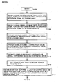
- Fig. 15 represents the waveform of the symbol transmitted in accordance with the OFDM scheme
- a signal represented by the bottom most waveform in Fig. 15 is employed as the transmission symbol of OFDM.
- inverse discrete Fourier transform is carried out on the baseband signal.
- discrete Fourier transform is applied on the reception signal through the algorithm of the so-called Fast Fourier Transform (FFT).
- FFT Fast Fourier Transform
- guard interval In the OFDM signal waveform in Fig. 15, a "guard interval" is provided before the valid symbol period. Such a guard interval has a portion of the valid symbol waveform, for example a signal of a predetermined time Tg at the tail of the valid symbol waveform, copied and added.
- the guard interval is provided as countermeasures against an interfering wave caused by multipath interference.
- the effect of the interfering wave is limited within the guard interval period if the delay time of the interfering wave is within the time set as the guard interval.
- Fig. 16 is a schematic diagram to describe a demodulation operation when such a desired wave and interfering wave are received
- a time window termed "FFT window” is provided in each symbol period, as shown in Fig. 16
- This time window denotes the section corresponding to the process of cutting out only the valid symbol section from the received OFDM transmission symbol.
- the FFT window is set equal to the valid symbol period length Ts.
- the guard interval period is set longer than the delay time of an interfering wave, as mentioned above. Accordingly, the orthogonality of each carrier wave of a reception wave can be maintained even if there is an interfering wave since a signal present in the guard interval period is a signal in the same valid symbol. Thus, demodulation with the effect of such an interfering wave removed can be carried out at the receiving side.
- the above-described multiple access of the SDMA scheme can be established by application of adaptive array technique.
- Fig 17 is a schematic block diagram to describe a configuration of such an adaptive array base station 3000
- adaptive array base station 3000 conducts transmission and reception using an adaptive array antenna including four antennas #1-#4, for the sake of simplification.
- description is based on a configuration directed to reception in accordance with the configuration of an adaptive array base station.
- adaptive array base station 3000 includes an A/D converter 3010 receiving signals from adaptive array antennas #1 - #4 to carry out detection and analog-digital conversion, and an FFT unit 3020 applying fast Fourier transform on a received digital signal from A/D converter 3010 to separate the signal for each carrier wave.
- the signal from the i-th antenna for the first carrier among the signals output from FFT unit 3020 is represented as signal f1, i (1, i: natural number).
- Adaptive array base station 3000 further includes N (N: total number of carriers) adaptive array blocks 3030.1-3030.N provided for each carrier.
- N total number of carriers
- Each adaptive array block receives the component of a corresponding carrier obtained by applying Fourier transform on the signal from antennas #1 - #4 through FFT unit 3020 to carry out adaptive array processing.
- Adaptive array block 3030.1 includes, likewise the adaptive array base station shown in Fig. 13, a reception weight vector calculator 3041 receiving signals f1, 1 - f1, 4 to calculate a reception weight vector, multipliers 3042-1 to 3042-4 receiving signals f1, 1 to f1, 4 at respective one inputs and the reception weight vector from reception weight vector calculator 3041 at respective other inputs, an adder 3043 to receive and combine the outputs of multipliers 3042-1 to 3042-4, and a memory 3044 to prestore a unique word signal (reference signal) used in the calculation of adaptive array processing by reception weight vector calculator 3041.
- Adder 3043 outputs a desired signal S1 (t) for carrier 1. This desired signal S1 (t) is also applied to reception weight vector calculator 3 041.
- the signal from a desired user can be separated for each carrier from a signal transmitted by the OFDM transmission scheme by adaptive array processing for reception.
- the signal of one channel is spread into a plurality of carriers for transmission in the OFDM scheme.
- the number of symbols of a reference signal included for each carrier is often not sufficient for the signals transmitted through the OFDM scheme.
- MMAC multimedia mobile access communication systems
- two symbols are defined for the reference signal for each OFDM carrier (subcarrier).
- Fig. 18 is a schematic diagram representing the timing of a signal received at adaptive array base station 3000 of Fig. 17.
- the section labeled "G" represents the above-described guard interval period of a reception signal.
- the primary desired wave is generally the first signal arriving at the base station.
- the first arriving signal is referred to as "head arriving signal” hereinafter.
- a signal arriving in delay within the guard interval period is called a "short delayed signal” whereas a signal arriving in delay for at least the guard interval period from the head arriving signal is referred to as a “long delayed signal”, under the influence of multipath.
- the route through which each of a head arriving signal, a short delayed signal, and a long delayed signal is transmitted is referred to as a "path”.
- the signal sampling timing in adaptive array block 3030.1 is denoted with an arrow.
- the sampling timing of a signal is to be set at a time interval sufficient for extracting a signal waveform for each carrier.
- a long delayed signal as shown in Fig. 18 can be removed.
- the bandwidth of a band-divided carrier is so narrow that a short delayed signal cannot be separated. Therefore, processing is carried out with the head arriving signal and the short delayed signal regarded as the same signal in adaptive array processing.
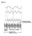
- Fig. 19 shows the intensity distribution of signals corresponding to respective carriers after passing through such an adaptive array.
- the spectrum of the head arriving signal (head wave) and the spectrum of a short delayed signal (short delayed wave) appear to be the same signal after the adaptive array processing, as mentioned above.
- the band for the entire carriers is extremely wide, there may be the case where the head wave and the short delayed wave are opposite in phase in the carrier indicated by the arrow in Fig. 19.
- Fig. 20 represents the intensity distribution when the signals for respective carriers are combined in the case of Fig. 19.
- adaptive array reception is conducted using a reference signal timed to the head wave, only a signal of small level can be extracted for the carrier of a frequency having the head signal and the short delayed signal in opposite phase.
- adaptive array reception is conducted for each carrier, only a signal of an extremely low signal level can be extracted for a carrier of a frequency that has the head wave and the short delayed wave in opposite phase, as shown in Fig. 19.
- a short delay component since a signal of a delay time within the guard interval (short delay component) has high correlation with the head signal, a short delay component will be included in the array combined output if combining based on the adaptive array is carried out using a reference signal timed to the head signal.
- a signal of a delay time within the guard interval short delay component
- the head wave and the short delayed wave are opposite in phase depending upon the carrier. In such a case, there will be a problem that combination at the maximum ratio is not conducted when viewed over the entire carrier.
- an approach of another configuration may be considered, conducting adaptive array processing on a signal prior to band-division by an FFT process.
- Fig. 21 is a schematic block diagram to describe a configuration of an adaptive array base station 4000 operating an adaptive array, calculating a common weight for all the carriers.
- adaptive array base station 4000 includes, likewise adaptive array base station 3000 of Fig. 17, an A/D converter 4010 applying detection and analog-digital conversion on signals received from four antennas #1 - #4, a reception weight vector calculator 4041 receiving outputs of A/D converter 4010 to calculate reception weight vectors for signals of respective antennas, multipliers 4042-1 to 4042-4 receiving signals from array antennas at respective one inputs, and receiving weight vectors from reception weight vector calculator 4041 at respective other inputs, an adder 4043 to receive and combine outputs from multipliers 4024-1 to 4042-4, a memory 4044 to prestore a reference signal employed in calculating weight vectors by reception weight vector calculator 4041, and an FFT unit 4050 applying fast Fourier transform processing on a received output from adder 4043 for separating into signals S 1(t) - S N(t) of the desired waves for respective carriers.
- the output from adder 4043 is applied to reception weight vector calculator 4041 to be used in the calculation of a reception weight vector.
- Fig. 22 is a schematic diagram to describe an operation of adaptive array base station 4000 of Fig. 21.
- G denotes a guard interval period.
- a long delayed signal can similarly be removed by adaptive array processing through an adaptive array block.
- the signal applied to an adaptive array block has an extremely wide band since it is not band-divided. In other words, a head arriving signal and a short delayed signal will be recognized as completely different signals at reception weight vector calculator 4041. Therefore, such short delayed signals will be removed by adaptive array processing.
- This operation is disadvantages in that, although the short delayed signal per se is a desired wave whose property may be improved if used effectively, such a short delayed signal will be removed by the adaptive array processing, resulting in the problem of degradation in communication quality.
- a short delayed signal will be regarded as an interfering signal, it will look as if a large number of interfering waves are arriving when viewed on part of adaptive array base station 4000. If directivity is established by the adaptive array in order to remove such signals, there is a possibility of no degree of freedom of the antenna left.
- An object of the present invention is to provide an adaptive array base station that can combine at the maximum ratio the multipath signals within a guard interval to improve reception sensitivity even in the case of adaptive array reception with respect to the OFDM transmission scheme.
- Another object of the present invention is to provide an adaptive array base station that can maintain the interference suppression performance without consuming the antenna degree of freedom in combining multipath signals within a guard interval period.
- a radio apparatus of the present invention for transmitting and receiving a signal transmitted with a guard interval section added to each valid symbol section by an orthogonal frequency division communication scheme employing a plurality of carries includes: an array antenna having a plurality of antennas; arriving timing detection means for detecting an arriving timing of a desired wave from signals received by the array antenna; reception response vector estimation means for estimating a first response vector for a signal arriving within the guard interval section from a head arriving wave of the desired wave, and a second response vector for a signal arriving after the guard interval section from the heard arriving wave of the desired wave; first Fourier transform means for applying Fourier transform on the first and second response vectors to extract components for respective ones of the plurality of carriers; second Fourier transform means for applying Fourier transform on reception signals from an array antenna to extract components for respective carriers of reception signals for respective ones of the antennas; and adaptive array processing means provided for every respective ones of the plurality of carriers, each adaptive array processing means receiving a component of a corresponding carrier from the second Fourier transform means among components for carriers
- the arriving timing detection means detects the desired wave in accordance with a cross correlation between the reception signal prior to Fourier transform in the second Fourier transform means and a reference signal including a training signal component corresponding to the plurality of carriers exceeding a predetermined threshold value, for each antenna.
- the reception response vector estimation means sets the response level to 0 in the first and second response vectors at a time other than the arriving timing detected by the arriving timing detection means.
- the adaptive array processing means provides a weight vector used to extract the desired wave for the corresponding carrier by a correlation matrix for each carrier, provided based on components for corresponding carriers of the first and second response vectors
- the arriving timing detection means detects an arriving timing of n (n: natural number, n ⁇ 1) interfering waves from a signal received from an array antenna
- the reception response vector estimation means estimates third to (2n+1)th response vectors for signals arriving within the guard interval section from each head arriving wave for each of the n interfering waves, and fourth to (2n+2)th response vectors for respective signals arriving after the guard interval section from each head arriving wave for each of said n interfering waves
- the first Fourier transform means further applies Fourier transform on the third to (2n+2)th response vectors to extract a component for each of the plurality of carriers
- the adaptive array processing means provides a weight vector used to extract the component of the corresponding carrier based on components for corresponding carriers of the first to (2n+2)th response vectors from the first Fourier transform means.
- the arriving timing detection means detects the desired wave and the interfering wave in accordance with a cross correlation between the reception signal prior to Fourier transform in the second Fourier transform means and a reference signal including a training signal component corresponding to the plurality of carriers exceeding a predetermined threshold value, for each antenna.
- the reception response vector estimation means sets a response level to 0 in the first to (2n+2)th response vectors at a time other than the arriving timing detected by the arriving timing detection means.
- the adaptive array processing means provides a weight vector used to extract the desired wave for the corresponding carrier by a correlation matrix for each carrier, provided based on components for corresponding carriers of the first to (2n+2)th response vectors.
- the adaptive array processing means provides a weight vector used to extract the interfering wave for the corresponding carrier by a correlation matrix for each carrier.
- the reception response vector estimation means estimates the first to (2n+2)th response vectors by the MMSE scheme.
- an adaptive array processing method to extract a signal transmitted with a guard interval section added to each valid symbol section by an orthogonal frequency division communication scheme employing a plurality of carriers for every component corresponding to the plurality of carriers by adaptive array processing includes the steps of: detecting an arriving timing of at least a desired wave from signals received by an array antenna having a plurality of antennas; estimating a first response vector for a signal arriving within the guard interval section from a head arriving wave out of the desired wave, and a second response vector for a signal arriving after the guard interface section from the head arriving wave of the desired wave; applying Fourier transform on the first and second response vectors to extract components for respective ones of the plurality of carriers; providing a weight vector used to separate by adaptive array processing a component corresponding to the carrier for a desired wave, based on components for carriers of at least first and second response vectors; applying Fourier transform on reception signals from the array antennas to extract carrier components of reception signals for respective antennas; and multiplying the weight vector by the carrier component of
- the step of detecting an arriving timing further includes the step of detecting the arriving timing of at least one interfering wave.
- the method further includes the steps of estimating a third response vector for a signal arriving within the guard interval section from the head arriving wave out of an interfering wave, and a fourth response vector for a signal arriving after the guard interval section from the head arriving wave out of the interfering wave; and applying Fourier transform on the third and fourth response vectors to extract components for respective ones of the plurality of carriers.
- the step of providing a weight vector provides the weight vector based on components for carriers of the first to fourth response vectors.
- Fig. 1 is a schematic block diagram to describe a configuration of adaptive array base station 1000 according to an embodiment of the present invention.
- Adaptive array base station 1000 of the present invention transmits and receives a signal having directivity by adaptive array processing with respect to a mobile station such as a user's terminal. It is to be noted that adaptive array base station 1000 can also transmit and receive a signal with respect to a mobile station through the spatial division multiple scheme as will be described afterwards.
- adaptive array base station 1000 includes an array antenna formed of n (n: natural number) antennas, an A/D converter 1010 to conduct detection and analog-digital conversion on signals received from array antennas #1 - #n, FFT units 1020.1 - 1020.n provided for respective n antennas, receiving outputs from A/D converter 1010 to separate and extract signals for respective carriers for corresponding antennas, a correlator 1030 receiving signals from A/D converter 1010 to detect arriving timings of a desired wave and an interfering wave, as will be described afterwards, a memory 1040 to store reference signals corresponding to the desired wave and the interfering wave in order to detect the arriving timings of the desired wave and the interfering wave at correlator 1030, a reception response vector estimator 1050 receiving signals prior to fast Fourier transform, applied to correlator 1030 from A/D converter 1010, and information on the arriving timing of a signal detected at correlator 1030 for estimating a response vector in a procedure that will be described
- FIG. 1 only adaptive array block 1070.k corresponding to the k-th carrier is depicted.
- Adaptive array block 1070.k includes a reception weight calculator 1072.k calculating a weight vector, multipliers 1080-1 to 1080-n receiving signals for the k-th carrier from FFT unit 1020.1 - 1020.n at respective one input nodes and the weight vector from reception weight calculator 1072.k at respective other input nodes, and an adder 1090 receiving and adding the signals from multipliers 1080-1 to 1080-n to output a desired signal Sk (t) for the k-th carrier.
- Fig. 2 is a schematic diagram to describe a reception signal of adaptive array base station 1000 shown in Fig. 1.
- the reception wave includes a desired wave S d (t), a delayed wave S d (t - ⁇ s ) of the desired wave, an interfering wave S u (t), and a delayed wave S u (t - ⁇ i ) of the interfering wave.
- time ⁇ s and time ⁇ i are the delayed time.
- the subscript "d" of a signal implies the signal of a desired wave.
- the signal of an interfering wave is represented by the subscript "u”.
- Fig. 3 is a schematic diagram to describe a configuration of desired wave S d (t) and an interfering wave S u (t).
- Desired wave S d (t) includes, but not exclusively, a reference signal section of two symbols (training signal section) at the beginning, and a data signal section continuous thereto, for example.
- reference signal d (t) is an inverse Fourier transform version of the training symbol of an input signal aligned in the frequency domain, and is a signal of a time domain.
- interfering wave S u (t) includes a reference signal section u (t) of two symbols at the beginning, and a data signal section continuous thereto, for example It is assumed that reference signal section d (t) of a desired wave is a signal differing from the reference signal section u (t) of an interfering wave without losing universality.
- adaptive array base station 1000 can identify the mobile station such as a user's terminal by such a different reference signals (training signals).
- Fig. 4 is a schematic diagram to describe an operation of correlator 1030 of adaptive array base station 1000 shown in Fig. 1.
- the signals applied to correlator 1030 include a head arriving signal S d (t), a short delayed signal S d (t - ⁇ 2 ) arriving at a delay time ⁇ 2 shorter than the guard interval period, and a long delayed signal S d (t - ⁇ 3 ) arriving at a delay time ⁇ 3 corresponding to at least the guard interval period for a desired wave, as well as a head arriving signal S u (t), a short delayed signal S u (t - ⁇ 2 ) arriving at a delay time ⁇ 2 shorter than the guard interval period, and a long delayed signal S u (t - ⁇ 3 ) arriving at a delay time ⁇ 3 corresponding to at least the guard interval period for an interfering wave.
- correlator 1030 samples a reception signal at a sufficiently short sampling timing to carry out signal processing prior to FFT processing.
- Signal X n (t) applied from antenna #n to correlator 1030 can be represented by the following equation (16).
- x n ( t ) h n , 1 s d ( t ) + h n , 2 s d ( t - ⁇ 2 ) + h n , 3 s d ( t - ⁇ 3 ) + ⁇ + p n , 1 s u ( t ) + p n , 2 s u ( t - ⁇ 2 ) + p n , 3 s u ( t - ⁇ 3 ) + ⁇ + n n ( t )
- h n,1 designates the response of the head wave (element of a response vector) of a desired wave received at the n-th antenna #n
- ⁇ n,1 designates the response of the head wave of an interfering wave (multiple party in SDMA) received at the n-th antenna #n.
- coefficients h n,2 and h n,3 designate the response of delayed waves of a desired wave (element of response vector) received at the n-th antenna #n.
- coefficients ⁇ n,2 and ⁇ n,3 designate the response of delayed waves of an interfering wave (multiple party in SDMA) received at the n-th antenna #n.
- signal S d (t) is a signal of a desired wave
- signal s u (t) is a signal of an interfering wave (multiple party in SDMA).
- correlation function ⁇ n,d (t) between the reference signal of a desired wave and the reception signal of antenna #n the correlation component between the desired wave and the reference signal, as well as a small correlation component I d (t) between the interfering wave and noise.
- Such a correlation function ⁇ n,d (t) or correlation function ⁇ n,u (t) is also termed “sliding correlation”.
- Fig. 5 represents the time dependence of such a correlation function ⁇ n,d (t).
- correlation function ⁇ n,d (t) is a signal, which is actually a complex number whose absolute value and phase on the complex plane change over time.
- Fig. 5 shows only the component in a predetermined direction on the complex plane.
- correlation function ⁇ n,d (t) includes a peak P1 as the head arriving signal component A peak P2 corresponding to the short delayed signal component immediately succeeds peak P2. Furthermore, there is a peak P3 corresponding to the long delayed signal component at a time behind peak P2 of the short delayed signal component.
- Fig. 6 represents the time dependency of the absolute value component of correlation function ⁇ n,d (t) shown in Fig. 8.
- value Vt indicates the threshold value used in the process that will be described afterwards.
- Correlation function ⁇ n,d (t) corresponds to the reception response (complex number) of a desired wave signal of the n-th antenna.
- the non-orthogonal component of noise and interference will remain in the complex response obtained by such correlation, leading to considerable error.
- the arriving time of the head arriving signal and the delay time of the arriving time of a delayed signal can be properly obtained by such correlation function ⁇ n,d (t).
- reception response vector estimator 1050 the procedure of obtaining more accurately the reception response of a wave from a desired user terminal and the reception response of a wave from an interfering user terminal using the delay time obtained by correlation functions ⁇ n,d (t) and ⁇ n,u (t) is performed by reception response vector estimator 1050 according to the steps set forth below.
- a threshold value Vt is preset for the absolute values
- a predetermined value is selected, or a standard such as extracting a signal lower than the highest signal level by a predetermined value is employed.
- MMSE Minimum Mean Square Error
- a signal train corresponding to sampled reception signals of the certain antenna is represented as below, identified as vector X.
- X [x 1 , x 2 , x 3 , ⁇ ] T
- the number of elements of such a vector can be set to, for example, 64 samples or 128 samples.
- Signals corresponding to an inverse Fourier transform on reference signals of a desired wave are represented as sd 1 , sd 2 , sd 3 , ⁇ .
- the reference signal for such a desired wave is represented as set forth below, corresponding to the vector formed of the above-described sampling values of reception signals.
- d k [ ⁇ , ⁇ , ⁇ , sd 1 , sd 2 , ⁇ ] T
- a plurality of elements represented as ⁇ are present, corresponding in number to delay time ⁇ k .
- the value of the element represented as ⁇ will include the component of an inverse Fourier transform on the signal present in a guard interval, when present, located before a reference signal.
- the time series of elements corresponding to an inverse Fourier transform on the reference signals of an interference signal is represented as su 1 , su 2 , ⁇ .
- the time series of reference signals of the interference signal is represented as set forth below, corresponding to vector X formed of sampling elements of a reception signal.
- the process of obtaining the response vector for the reception signal of, for example, the n-th antenna corresponds to obtaining a response h k and a response ⁇ k ' for the desired wave and interfering wave, respectively, so as to minimize an evaluation function J 1 represented by the following equation (22).
- evaluation function J 1 is represented as equation (25).
- vector a (Q H Q) -1 Q H x
- the above-described procedure is based on the provision for the n-th antenna. This procedure is similarly carried out for other antennas to obtain the response of a desired wave and the interfering wave for each antenna.
- Signals other than those picked up as having at least the threshold value and having the complex response estimated are all set to the signal level of 0.
- the remaining noise and interfering component can be removed.
- the complex response is set to 0.
- the reception response of ⁇ n,dd (t) is placed for a desired wave whereas a reception response (correlation function) of ⁇ n,ud (t) is placed for an interfering wave.
- the subscript "dd” denotes a signal within the guard interval for a desired wave.
- Subscript "ud” denotes a signal within the guard interval for an interfering wave.
- subscript "du” denotes a delayed wave longer than the guard interval time for a desired wave.
- Subscript “uu” denotes a delayed wave having a delay time longer than the guard interval time for an interfering wave.
- the response for an interfering wave obtained as described above corresponds to the complex response for multiple user in SDMA
- Fig. 7 represents the time variation of response ⁇ n,dd (t) and response ⁇ n,du (t) calculated as described above.
- Fig. 7 There are three paths in Fig. 7.
- the signals from paths 1 and 2 for the head arriving wave and the first delayed wave have arrived at the base station within the guard interval length.
- the delayed wave corresponding to path 3 has arrived at adaptive array base station 1000 at an elapse of a delayed time of at least the guard interval time from the arriving time of the head wave.
- response ⁇ n,dd (t) includes two peaks whereas response ⁇ n,du (t) includes one peak.
- a first response vector formed of the response of each antenna corresponding to response ⁇ n,dd (t) and a second response vector formed of the response of each antenna corresponding to response ⁇ n,du (t) are provided for a desired wave.
- a third response vector formed of the response of each antenna corresponding to response ⁇ n,ud (t) and a fourth response vector formed of the response of each antenna corresponding to response ⁇ n,uu (t) are provided.
- reception response vector estimator 1050 a response for each antenna is obtained at reception response vector estimator 1050.
- FFT units 1060.1 -1060.n perform the process set forth below.
- Fig. 8 shows complex response ⁇ n,dd (t) and a corresponding complex response ⁇ n,dd (k) for each carrier obtained by fast Fourier transform.
- a similar operation is carried out on all the antennas to calculate the complex response for each carrier of all the antennas.
- a response vector with the complex response of each carrier as an element is calculated.
- complex response ⁇ n,du (t) is subjected to fast Fourier transform to obtain complex response ⁇ n,du (k) for each carrier.
- a response vector d d (k) for a signal arriving within the guard interval period for the k-th carrier is represented by equation (27)
- the response vector d u (k) of the kth carrier from complex response ⁇ n,du (t) of a signal arriving at a delay time of at least the guard interval, transmitted from a desired terminal is calculated by equation (28).
- d d (k) ⁇ 1, dd (k), ⁇ 2, dd (k), ⁇ , ⁇ n, dd (k) ⁇ T
- d u (k) ⁇ 1, du (k), ⁇ 2, du (k), ⁇ , ⁇ n, du (k) ⁇ T
- complex response ⁇ n,uu (t) of a signal arriving after the guard interval period for an interfering wave is subjected to fast Fourier transform to be converted into a response ⁇ n,uu (k) for each carrier.
- a response vector i u (k) for an interfering wave arriving at a delay time of at least the guard interval is represented by equation (30).
- i d (k) ⁇ 1, ud (k), ⁇ 2, ud (k), ⁇ , ⁇ n, ud (k) ⁇ T
- i u (k) ⁇ 1, uu (k), ⁇ 2, uu (k), ⁇ , ⁇ n, uu (k) ⁇ T
- such a response vector is calculated for each interfering wave or multiple user.
- reception weight calculator 1070 Based on the response vector of the k-th carrier for each antenna obtained by fast Fourier transform as described above, reception weight calculator 1070. k calculates the reception weight vector for the k-th carrier as set forth below.
- the response vector d d (k) of a desired wave of a delay time within the guard interval, the response vector d u (k) of a desired wave of a delay time exceeding the guard interval, the response vector i d (k)) of an interfering wave of a delay time within the guard interval, and the response vector i u (k) of an interfering wave with a delay time exceeding the guard interval for the k-th carrier are obtained by FFT units 1060.1 - 1060.n as below.
- the reception weight vector for a party of a multiple signal in the case of SDMA is calculated by equation (34).
- ⁇ 2 is a positive real number. This value may be obtained empirically, avoiding singularity of the correlation matrix. Alternatively, a value of thermal noise power of the system may be selected. I represents the unit matrix of n ⁇ n.
- Figs. 9 and 10 are flow charts to describe the overall operation of adaptive array base station 100.
- step S100 upon initiation of the process (step S100), the sliding correlation between the reception signal for each antenna of the array antenna and the reference signal of a desired wave is taken in correlator 1030 (step S102).
- the sliding correlation between the reception signal and reference signal of an interfering wave for each antenna of the array antenna is also obtained (step S104).
- a signal having the absolute value of a correlation value exceeding a predetermined threshold value for a desired wave and a signal having an absolute value of a correlation value exceeding the predetermined threshold value for an interfering wave are picked up (step S106, S108).
- the complex response for the signals picked up is estimated by MMSE and the like for a desired wave and an interfering wave (step S110). All the signals other than the signals picked up are set to the signal level of 0 (step S112).
- reception response vector estimator 1050 a reception response ⁇ n,dd (t) for a desired wave and a reception response ⁇ n,ud (t) for an interfering wave are obtained with the signal component of a delay time longer than the guard interval set to 0 (step S114).
- Reception response vector estimator 1050 also obtains a reception response ⁇ n,du (t) for a desired wave and a reception response ⁇ n,uu (t) for an interfering wave with the signal component of a delay time shorter than the guard interval set to 0 (step S116).
- FFT units 1060.1 - 1060.n apply Fourier transform on reception response ⁇ n,dd (t), reception response ⁇ n,ud (t), reception response ⁇ n,du (t) and reception response ⁇ n,uu (t) to obtain the complex response of each carrier for each antenna (step S118).
- a complex response vector d d (k) for every carrier corresponding to a signal arriving with a delay within the guard interval of the desired wave 2) a complex response vector d u (k) for every carrier corresponding to a signal arriving with a delay exceeding the guard interval of the desired wave, 3) a complex response vector i d (k) for every carrier corresponding to a signal arriving with a delay within the guard interval of an interfering wave, and 4) a complex response vector i u (k) for every carrier corresponding to a signal arriving with a delay exceeding the guard interval of the interfering wave are provided (step S120).
- a correlation matrix R XX (k) of the k-th carrier is provided, based on the calculated complex response vector.
- the weight vector for the k-th carrier is calculated with respect to a desired wave (step S122).
- the signal of each carrier obtained by applying Fourier transform on the reception signal from each antenna in the array antenna is multiplied by the weight vector to extract the desired signal for the k-th carrier (step 124).
- the weight vector is obtained also for an interfering wave, if necessary, to extract an interfering wave.
- the processing ends (step S130).
- the reason why a short delayed signal is combined without being attenuated by the phase difference from the head arriving wave in the above method may be due to an adaptive array operation being carried out so as to direct the beam to each of the head signal and short delayed signal for every carrier since response vector d d (k) for each carrier includes both the components of the head signal and short delayed signal.
- null control In the case where null control is to be conducted on all the signals without depending upon the above-described scheme, control to direct null to a short delay will also have to be provided. In this case, the degree of freedom is insufficient for an antenna of 4 elements. Sufficient properties cannot be achieved.
- a complex response of a desired signal and a complex response of an interfering signal were obtained in accordance with a method described with reference to equations (22) - (26) as an operation of reception response vector estimator 1050.
- the second embodiment is directed to a method of obtaining a complex response of a desired signal and a complex response of an interference signal applicable even in such a case.
- Equation (35) can be rewritten as below.
- J 2 ⁇ X - Q'h ⁇ 2
- reception response vector estimator 1050 performing the above-described estimation method of a complex response
- usage of a configuration of an adaptive array base station of the present invention allows a multipath signal within a guard interval to be combined at the maximum ratio to maximize the reception sensitivity. Furthermore, the antenna degree of freedom is not consumed when a multipath signal within the guard interval is combined. The interference suppression performance can be maintained.
- the reception sensitivity can be improved even in the case of adaptive array reception for the OFDM transmission scheme.
- the present invention is particularly useful in an adaptive array base station.
Applications Claiming Priority (3)
| Application Number | Priority Date | Filing Date | Title |
|---|---|---|---|
| JP2001319308A JP3814182B2 (ja) | 2001-10-17 | 2001-10-17 | 無線装置およびアダプティブアレイ処理方法 |
| JP2001319308 | 2001-10-17 | ||
| PCT/JP2002/010637 WO2003034617A1 (fr) | 2001-10-17 | 2002-10-11 | Appareil radio et procédé de traitement de réseau adaptatif |
Publications (2)
| Publication Number | Publication Date |
|---|---|
| EP1443680A1 true EP1443680A1 (fr) | 2004-08-04 |
| EP1443680A4 EP1443680A4 (fr) | 2010-01-13 |
Family
ID=19136880
Family Applications (1)
| Application Number | Title | Priority Date | Filing Date |
|---|---|---|---|
| EP02775346A Withdrawn EP1443680A4 (fr) | 2001-10-17 | 2002-10-11 | Appareil radio et proc d de traitement de r seau adaptatif |
Country Status (6)
| Country | Link |
|---|---|
| US (1) | US7423961B2 (fr) |
| EP (1) | EP1443680A4 (fr) |
| JP (1) | JP3814182B2 (fr) |
| KR (1) | KR100659616B1 (fr) |
| CN (1) | CN100336319C (fr) |
| WO (1) | WO2003034617A1 (fr) |
Cited By (4)
| Publication number | Priority date | Publication date | Assignee | Title |
|---|---|---|---|---|
| EP1737176A1 (fr) * | 2005-06-20 | 2006-12-27 | NTT DoCoMo, Inc. | Signalisation pour l'allocation d'une liaison de communication dans un système MIMO |
| WO2007062261A1 (fr) * | 2005-11-28 | 2007-05-31 | Kyocera Corporation | Systeme de station de base et procede pour attribuer un mot unique dans un systeme de transmission |
| EP2052470A2 (fr) * | 2006-12-04 | 2009-04-29 | NTT DoCoMo Inc. | Procédé permettant une sélection de seuil optimal des dispositifs d'estimation du temps d'arrivée |
| US8320343B2 (en) * | 2002-09-20 | 2012-11-27 | Kyocera Corporation | Radio cell station apparatus, reference signal allocation method and reference signal allocation program |
Families Citing this family (37)
| Publication number | Priority date | Publication date | Assignee | Title |
|---|---|---|---|---|
| WO2002054627A1 (fr) * | 2000-12-27 | 2002-07-11 | Sanyo Electric Co., Ltd. | Appareil radio, programme et procede de detection de permutation |
| JP2003143047A (ja) * | 2001-11-01 | 2003-05-16 | Sony Corp | アダプティブアレーアンテナ及びそのキャリブレーション方法 |
| EP1540832B1 (fr) * | 2002-08-29 | 2016-04-13 | Callahan Cellular L.L.C. | Procede de separation de signaux d'interference et de calcul d'angles d'arrivee |
| JP3891427B2 (ja) * | 2002-12-27 | 2007-03-14 | 富士通株式会社 | 適応アレーアンテナ制御装置 |
| JP3998578B2 (ja) * | 2003-01-09 | 2007-10-31 | 株式会社東芝 | 移動通信システムおよび移動通信方法 |
| JP4163971B2 (ja) * | 2003-02-06 | 2008-10-08 | 松下電器産業株式会社 | 送信装置及び送信方法 |
| US20050078735A1 (en) * | 2003-07-18 | 2005-04-14 | David Baker | Communications systems and methods |
| US20050113141A1 (en) * | 2003-11-20 | 2005-05-26 | Telefonaktiebolaget Lm Ericsson (Publ) | Spatial joint searcher and channel estimators |
| JP3910956B2 (ja) * | 2003-12-26 | 2007-04-25 | 株式会社東芝 | Ofdm無線通信システムのための伝搬路推定器及びこれを用いた受信装置 |
| US7983142B2 (en) | 2004-03-30 | 2011-07-19 | Intel Corporation | Apparatus, systems, and methods for the reception and synchronization of asynchronous signals |
| JP4496836B2 (ja) | 2004-04-23 | 2010-07-07 | ブラザー工業株式会社 | 無線受信装置 |
| US20050265219A1 (en) * | 2004-05-11 | 2005-12-01 | Texas Instruments Incorporated | Orthogonal frequency division multiplex (OFDM) packet detect unit, method of detecting an OFDM packet and OFDM receiver employing the same |
| JP4464403B2 (ja) | 2004-06-04 | 2010-05-19 | パナソニック株式会社 | 無線通信装置 |
| KR100703523B1 (ko) | 2005-01-17 | 2007-04-03 | 삼성전자주식회사 | 직교 주파수 분할 다중 수신기에서 에러 벡터 크기를감소시키기 위한 방법 및 장치 |
| KR100587999B1 (ko) * | 2005-03-25 | 2006-06-08 | 한국전자통신연구원 | 스마트 안테나를 갖는 직교 주파수 분할 다중 접속시스템에서의 상향 링크 반송파 주파수 동기화 및 안테나가중치 벡터 추정 방법 및 그 장치 |
| KR100657515B1 (ko) * | 2005-12-10 | 2006-12-14 | 한국전자통신연구원 | 직교 주파수분할 다중접속 시스템의 하향링크 빔형성 장치및 이 장치를 포함하는 송신 장치 |
| JP4854315B2 (ja) * | 2006-01-27 | 2012-01-18 | 三洋電機株式会社 | 受信方法および装置 |
| JP4708206B2 (ja) * | 2006-02-10 | 2011-06-22 | 日本電信電話株式会社 | 無線通信方法及び無線基地局 |
| JP4664234B2 (ja) * | 2006-05-24 | 2011-04-06 | 富士通セミコンダクター株式会社 | Ofdm受信機 |
| JP4732239B2 (ja) | 2006-05-29 | 2011-07-27 | 京セラ株式会社 | 無線基地局及び無線基地局の制御方法 |
| JP4836186B2 (ja) * | 2006-05-31 | 2011-12-14 | 三洋電機株式会社 | 送信装置 |
| WO2008027622A2 (fr) * | 2006-09-01 | 2008-03-06 | Intermec Ip Corp. | Étiquettes rfid avec des capacités de communication cdma |
| US8587406B2 (en) * | 2006-09-01 | 2013-11-19 | Intermec Ip Corp. | RFID tags with orthogonal communication capabilities, and associated systems |
| US8508369B2 (en) * | 2006-09-01 | 2013-08-13 | Intermec Ip Corp. | RFID tag system with block coding, such as space-time block coding |
| WO2008049076A2 (fr) * | 2006-10-18 | 2008-04-24 | Genesis Microchip Inc. | Synchronisation de symboles utilisant une discontinuité de phase pour des systèmes dvb-t dans des canaux awgn |
| JP4829849B2 (ja) * | 2006-11-15 | 2011-12-07 | 日本放送協会 | Ofdm信号合成用受信装置および中継装置 |
| KR100847015B1 (ko) * | 2006-12-08 | 2008-07-17 | 한국전자통신연구원 | 빔 포밍 방법 및 그 장치 |
| JP2008160569A (ja) * | 2006-12-25 | 2008-07-10 | Kyocera Corp | Ofdm方式の通信システム、基地局、端末及び通信方法 |
| WO2008103089A1 (fr) * | 2007-02-22 | 2008-08-28 | Telefonaktiebolaget Lm Ericsson (Publ) | Procédé et dispositif pour réduire l'interférence dans un système d'accès cellulaire |
| JP4929481B2 (ja) * | 2008-08-15 | 2012-05-09 | 株式会社シンセシス | ダイバーシチ受信機 |
| EP2211512B1 (fr) * | 2009-01-23 | 2017-12-27 | Telefonaktiebolaget LM Ericsson (publ) | Appareil et procédé de compensation de l'étalement de retards |
| JP5570456B2 (ja) * | 2011-02-18 | 2014-08-13 | 日本放送協会 | Ofdm信号受信装置および中継装置 |
| CN103747538B (zh) * | 2014-01-09 | 2017-02-15 | 京信通信系统(中国)有限公司 | 自适应载波分离方法及装置 |
| RU2580830C1 (ru) * | 2014-12-29 | 2016-04-10 | Федеральное государственное бюджетное образовательное учреждение высшего профессионального образования "Московский государственный технический университет имени Н.Э. Баумана (МГТУ им. Н.Э. Баумана) | Радиолокационный пеленгатор локализованных объектов |
| CN109690970B (zh) * | 2016-09-15 | 2022-06-10 | 三菱电机株式会社 | 无线接收装置和期望信号检测方法 |
| RU2646602C1 (ru) * | 2017-07-13 | 2018-03-06 | федеральное государственное казенное военное образовательное учреждение высшего образования "Военная академия связи имени Маршала Советского Союза С.М. Буденного" Министерства обороны Российской Федерации | Широкополосное приемопередающее устройство с программной перестройкой фазы сигнала |
| WO2019117762A1 (fr) * | 2017-12-11 | 2019-06-20 | Telefonaktiebolaget Lm Ericsson (Publ) | Détermination de pondérations de formation de faisceau directionnel |
Citations (4)
| Publication number | Priority date | Publication date | Assignee | Title |
|---|---|---|---|---|
| JPH11275047A (ja) * | 1998-03-20 | 1999-10-08 | Sharp Corp | 送信機、受信機および伝送方法 |
| US6144711A (en) * | 1996-08-29 | 2000-11-07 | Cisco Systems, Inc. | Spatio-temporal processing for communication |
| US6249250B1 (en) * | 1998-01-08 | 2001-06-19 | Kabushiki Kaisha Toshiba | Adaptive variable directional antenna |
| EP1130840A2 (fr) * | 2000-02-29 | 2001-09-05 | Kabushiki Kaisha Toshiba | Modulation multiporteuse à étalage du spectre pour la communication cellulaire |
Family Cites Families (7)
| Publication number | Priority date | Publication date | Assignee | Title |
|---|---|---|---|---|
| JP3381580B2 (ja) | 1996-11-22 | 2003-03-04 | 株式会社豊田中央研究所 | アダプティブ通信装置 |
| JP3567734B2 (ja) | 1998-04-28 | 2004-09-22 | 株式会社豊田中央研究所 | アダプティブ受信装置 |
| US6898235B1 (en) * | 1999-12-10 | 2005-05-24 | Argon St Incorporated | Wideband communication intercept and direction finding device using hyperchannelization |
| US6920192B1 (en) * | 2000-08-03 | 2005-07-19 | Lucent Technologies Inc. | Adaptive antenna array methods and apparatus for use in a multi-access wireless communication system |
| JP4374764B2 (ja) * | 2000-10-31 | 2009-12-02 | 株式会社デンソー | アダプティブ受信機 |
| US6603427B2 (en) * | 2001-06-27 | 2003-08-05 | Raytheon Company | System and method for forming a beam and creating nulls with an adaptive array antenna using antenna excision and orthogonal Eigen-weighting |
| US7359466B2 (en) * | 2001-08-24 | 2008-04-15 | Lucent Technologies Inc. | Signal detection by a receiver in a multiple antenna time-dispersive system |
-
2001
- 2001-10-17 JP JP2001319308A patent/JP3814182B2/ja not_active Expired - Fee Related
-
2002
- 2002-10-11 WO PCT/JP2002/010637 patent/WO2003034617A1/fr active Application Filing
- 2002-10-11 EP EP02775346A patent/EP1443680A4/fr not_active Withdrawn
- 2002-10-11 KR KR1020047005670A patent/KR100659616B1/ko not_active IP Right Cessation
- 2002-10-11 CN CNB028249593A patent/CN100336319C/zh not_active Expired - Fee Related
- 2002-10-11 US US10/492,351 patent/US7423961B2/en not_active Expired - Fee Related
Patent Citations (4)
| Publication number | Priority date | Publication date | Assignee | Title |
|---|---|---|---|---|
| US6144711A (en) * | 1996-08-29 | 2000-11-07 | Cisco Systems, Inc. | Spatio-temporal processing for communication |
| US6249250B1 (en) * | 1998-01-08 | 2001-06-19 | Kabushiki Kaisha Toshiba | Adaptive variable directional antenna |
| JPH11275047A (ja) * | 1998-03-20 | 1999-10-08 | Sharp Corp | 送信機、受信機および伝送方法 |
| EP1130840A2 (fr) * | 2000-02-29 | 2001-09-05 | Kabushiki Kaisha Toshiba | Modulation multiporteuse à étalage du spectre pour la communication cellulaire |
Non-Patent Citations (1)
| Title |
|---|
| See also references of WO03034617A1 * |
Cited By (6)
| Publication number | Priority date | Publication date | Assignee | Title |
|---|---|---|---|---|
| US8320343B2 (en) * | 2002-09-20 | 2012-11-27 | Kyocera Corporation | Radio cell station apparatus, reference signal allocation method and reference signal allocation program |
| EP1737176A1 (fr) * | 2005-06-20 | 2006-12-27 | NTT DoCoMo, Inc. | Signalisation pour l'allocation d'une liaison de communication dans un système MIMO |
| WO2007062261A1 (fr) * | 2005-11-28 | 2007-05-31 | Kyocera Corporation | Systeme de station de base et procede pour attribuer un mot unique dans un systeme de transmission |
| US7664071B2 (en) | 2005-11-28 | 2010-02-16 | Kyocera Corporation | Base station system and method for assigning a unique word in a communication system |
| EP2052470A2 (fr) * | 2006-12-04 | 2009-04-29 | NTT DoCoMo Inc. | Procédé permettant une sélection de seuil optimal des dispositifs d'estimation du temps d'arrivée |
| EP2052470A4 (fr) * | 2006-12-04 | 2010-05-05 | Ntt Docomo Inc | Procédé permettant une sélection de seuil optimal des dispositifs d'estimation du temps d'arrivée |
Also Published As
| Publication number | Publication date |
|---|---|
| CN100336319C (zh) | 2007-09-05 |
| KR100659616B1 (ko) | 2006-12-20 |
| JP3814182B2 (ja) | 2006-08-23 |
| WO2003034617A1 (fr) | 2003-04-24 |
| CN1605167A (zh) | 2005-04-06 |
| EP1443680A4 (fr) | 2010-01-13 |
| KR20040051610A (ko) | 2004-06-18 |
| US7423961B2 (en) | 2008-09-09 |
| US20040246889A1 (en) | 2004-12-09 |
| JP2003124857A (ja) | 2003-04-25 |
Similar Documents
| Publication | Publication Date | Title |
|---|---|---|
| US7423961B2 (en) | Radio apparatus and adaptive array processing method | |
| US6512737B1 (en) | Stacked carrier discrete multiple tone communication system | |
| JP4968339B2 (ja) | マルチセクタ化した無線通信システムに対する信号処理システム及びその方法 | |
| KR100559070B1 (ko) | 적응형 안테나 어레이 및 그 제어 방법 | |
| US6826240B1 (en) | Method and device for multi-user channel estimation | |
| US6504506B1 (en) | Method and device for fixed in time adaptive antenna combining weights | |
| US6442214B1 (en) | Diversity transmitter based on linear transform processing of transmitted information | |
| JP4703185B2 (ja) | サブアレイ選択付きアレイ受信機およびその使用方法ならびにそれを組み込んだ受信システム | |
| US7519125B2 (en) | Multicarrier receiver and methods of generating spatial correlation estimates for signals received with a plurality of antennas | |
| US20090225741A1 (en) | Wireless system using a new type of preamble for a burst frame | |
| EP1119932A1 (fr) | Technologie dmt a empilement de porteuses | |
| WO2006075732A1 (fr) | Appareil de communication sans fil | |
| JP4755629B2 (ja) | 送受信装置とその通信方法 | |
| US10785060B2 (en) | Efficient channel estimation and symbol detection for massive MIMO-OFDM | |
| US6711412B1 (en) | Interference mitigation in wireless communications by training of interfering signals | |
| KR100729727B1 (ko) | Ofdma 이동통신 시스템에서의 간섭을 제거하는 수신방법 및 장치 | |
| EP1530333A1 (fr) | Procédé d'estimation de canal dans un système MIMO-OFDM | |
| JP4077830B2 (ja) | 無線装置およびアダプティブアレイ処理方法 | |
| JP4704375B2 (ja) | 送受信装置とその通信方法 | |
| KR101207657B1 (ko) | 적응 배열 안테나를 이용하는 직교주파수분할다중 통신시스템에서 신호대잡음비 혹은 신호대간섭과잡음비를최대로 하는 신호처리 장치 및 방법 | |
| JP2001223624A (ja) | 無線受信装置 | |
| CN115842611A (zh) | 映射方法、装置、设备及存储介质 | |
| Wang et al. | Carrier aggregation receiver with beamformer and compensation of doppler effects and timing offset | |
| Pejoski et al. | Multiple speaker/microphone platform as an educational tool for wireless communications | |
| Zhang et al. | Downlink Channel Estimation Model for 802.16 e OFDMA System |
Legal Events
| Date | Code | Title | Description |
|---|---|---|---|
| PUAI | Public reference made under article 153(3) epc to a published international application that has entered the european phase |
Free format text: ORIGINAL CODE: 0009012 |
|
| 17P | Request for examination filed |
Effective date: 20040512 |
|
| AK | Designated contracting states |
Kind code of ref document: A1 Designated state(s): AT BE BG CH CY CZ DE DK EE ES FI FR GB GR IE IT LI LU MC NL PT SE SK TR |
|
| AX | Request for extension of the european patent |
Extension state: AL LT LV MK RO SI |
|
| A4 | Supplementary search report drawn up and despatched |
Effective date: 20091214 |
|
| RIC1 | Information provided on ipc code assigned before grant |
Ipc: H04B 7/08 20060101ALI20091208BHEP Ipc: H04B 7/06 20060101ALI20091208BHEP Ipc: H04J 11/00 20060101ALI20091208BHEP Ipc: H04B 7/10 20060101AFI20030506BHEP |
|
| 17Q | First examination report despatched |
Effective date: 20100319 |
|
| STAA | Information on the status of an ep patent application or granted ep patent |
Free format text: STATUS: THE APPLICATION HAS BEEN WITHDRAWN |
|
| 18W | Application withdrawn |
Effective date: 20130802 |