EP1443677A1 - Appareil électrique - Google Patents
Appareil électrique Download PDFInfo
- Publication number
- EP1443677A1 EP1443677A1 EP04000557A EP04000557A EP1443677A1 EP 1443677 A1 EP1443677 A1 EP 1443677A1 EP 04000557 A EP04000557 A EP 04000557A EP 04000557 A EP04000557 A EP 04000557A EP 1443677 A1 EP1443677 A1 EP 1443677A1
- Authority
- EP
- European Patent Office
- Prior art keywords
- housing
- component
- signal
- electrical device
- transmission device
- Prior art date
- Legal status (The legal status is an assumption and is not a legal conclusion. Google has not performed a legal analysis and makes no representation as to the accuracy of the status listed.)
- Withdrawn
Links
- 230000008054 signal transmission Effects 0.000 claims abstract description 23
- 230000001939 inductive effect Effects 0.000 claims abstract description 4
- 238000005192 partition Methods 0.000 claims description 7
- 230000035699 permeability Effects 0.000 claims description 2
- 238000012216 screening Methods 0.000 abstract 1
- 239000000463 material Substances 0.000 description 7
- 230000000694 effects Effects 0.000 description 5
- 230000006866 deterioration Effects 0.000 description 2
- 230000005540 biological transmission Effects 0.000 description 1
- 230000005672 electromagnetic field Effects 0.000 description 1
- 230000005670 electromagnetic radiation Effects 0.000 description 1
- 230000005415 magnetization Effects 0.000 description 1
- 238000004519 manufacturing process Methods 0.000 description 1
- 239000002245 particle Substances 0.000 description 1
Images
Classifications
-
- H—ELECTRICITY
- H04—ELECTRIC COMMUNICATION TECHNIQUE
- H04B—TRANSMISSION
- H04B5/00—Near-field transmission systems, e.g. inductive or capacitive transmission systems
- H04B5/20—Near-field transmission systems, e.g. inductive or capacitive transmission systems characterised by the transmission technique; characterised by the transmission medium
- H04B5/24—Inductive coupling
- H04B5/26—Inductive coupling using coils
- H04B5/266—One coil at each side, e.g. with primary and secondary coils
Definitions
- the invention relates to an electrical device with a Housing and one arranged in the region of a housing wall Signal transmission device for transmitting a signal between the inside of the housing and the outside of the housing.
- Electrical devices are designed in this way if communication with other devices is established should or external components to the electrical device should be connected.
- the leading out of electrical signals by means of the Through sockets or plugs described is in the Manufacturing the device is problematic because the assembly of the Cables, plugs or sockets are time consuming and is prone to errors.
- the housing is usually designed so that it provides shielding against electromagnetic fields. To achieve a good shielding effect, it is important that there are no openings in the housing, since these the shielding effect deteriorate considerably.
- the provision of Breakthroughs for leading out signals thus represents a Measure that, although the transmission of signals to Outside allows, but at the same time the electrical Properties related to electromagnetic Tolerability deteriorated.
- the high frequency tightness also deteriorates protection against electrostatic discharge. Besides also deteriorate the mechanical strength of the Housing.
- the object of the invention is to have an electrical device specify a signal transmission device in which a Leading out an electrical signal or that Introducing an electrical signal is possible and mechanical strength and protection at the same time against electromagnetic radiation is preserved.
- an electrical Device of the type mentioned solved that is characterized in that the signal transmission device a first component disposed within the housing and a second component arranged outside the housing between which there is a shielding section extends, the first and the second component each have a coil and the two coils an inductive Form transformer.
- a signal transmission device which an inductive transformer and has an intermediate shielding section a contactless transmission of a signal between the Inside and outside of the housing allows without thereby the shielding properties of the housing be affected.
- the shielding Section formed by part of the housing wall, so that neither a breakthrough must be provided that leads to a Deterioration of the mechanical properties of the housing leads, a complex assembly of cables, plugs or Bushes must be provided.
- the shielding Section through an opening in the housing wall used cover part, for example a lid provided.
- This optimizes the local Material properties enables, so that in the area of Signal transmission device for transmitting the signal particularly suitable material can be used while the rest of the housing mechanically and in the shielding effect optimized materials are used.
- the shielding Section formed by a partition that in a Unit forming signal transmission device arranged and is therefore an electromagnetic closure of a Breakthrough in the housing wall caused by the Signal transmission device extends.
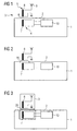
- FIG. 1 of an electrical device shows in a housing 1 first component 4 of a signal transmission device 3.
- a signal generated in an electrical component 10 is turned on given a coil 7.
- a magnetic field is generated.
- outside the housing 1 there is also a coil 8 provided with in the embodiment shown an antenna 9 is connected.
- the second coil 8 is part a second component 5 of the signal transmission device 3.
- the induced voltage in the second coil 8 is proportional to that applied to the first coil 7 Tension.
- a section 6 of a housing wall 2 of the housing 1 extends between the two coils 7 and 8.
- the material of the housing wall 2 or of the section 6 of the housing wall 2 is selected such that on the one hand the requirements with regard to the electromagnetic compatibility of the device are met and on the other hand but the shielding effect is not too strong to effect the transmission of a signal from the first coil 7 to the second coil 8 via a magnetic field.
- the permeability number ⁇ r of the material of the shielding section 6 should not be too large, since too much energy would be lost due to the constant magnetization of ferroelectric particles.
- a signal generating Component 10 is provided, which feeds the coil 7. How and what generates the signal plays for the invention However, no essential role, therefore the Control circuit for the coil 7 not shown in detail.
- the second component 5 of the signal transmission device is equipped with an antenna 9, through which the coil 7 signal transmitted to the coil 8 can be emitted. Instead, there is also an electrical connection conceivable.
- the basic circuit of Figure 1 also leaves open whether and how other circuit components are provided in the second component 5.
- FIG. 2 shows a second exemplary embodiment of a electrical device according to the invention shown.
- the Housing wall 2 of the housing 1 is not continuous, but has a breakthrough.
- a Cover 16 having screen properties used. While the housing 1 and the housing wall 2 from one Made of material that is particularly good shielding Has properties, the lid 16 is through used material adjusted so that an improved Efficiency of the transformer 7 and 8 is reached. Because it is only a small section of the housing 1, which is covered by the lid 16 may be worse Properties related to electromagnetic Tolerability to be accepted.
- FIG. 3 shows a third exemplary embodiment shown in which also a breakthrough in the Housing wall 2 is provided.
- a signal transmission device 3 which as one-piece component is formed and in illustrated embodiment from the inside by the Breakthrough in the housing wall 2 extends.
- a partition 26 Inside the Signal transmission device 3 is a partition 26 provided, which represents a continuation of the housing wall 2, i.e. the high-frequency closure of the breakthrough causes.
- the Partition 26 in the same plane as the housing wall, this is however not necessary, the partition could for example also be trough-shaped.
- the contactless transfer from the housing interior to the housing exterior is compared to other circuit components of the shield electrical device. Depending on the selected However, this is not the working frequency of the transmitter required.
Landscapes
- Engineering & Computer Science (AREA)
- Computer Networks & Wireless Communication (AREA)
- Signal Processing (AREA)
- Shielding Devices Or Components To Electric Or Magnetic Fields (AREA)
Applications Claiming Priority (2)
| Application Number | Priority Date | Filing Date | Title |
|---|---|---|---|
| DE10303456 | 2003-01-29 | ||
| DE10303456A DE10303456A1 (de) | 2003-01-29 | 2003-01-29 | Elektrisches Gerät |
Publications (1)
| Publication Number | Publication Date |
|---|---|
| EP1443677A1 true EP1443677A1 (fr) | 2004-08-04 |
Family
ID=32603018
Family Applications (1)
| Application Number | Title | Priority Date | Filing Date |
|---|---|---|---|
| EP04000557A Withdrawn EP1443677A1 (fr) | 2003-01-29 | 2004-01-13 | Appareil électrique |
Country Status (2)
| Country | Link |
|---|---|
| EP (1) | EP1443677A1 (fr) |
| DE (1) | DE10303456A1 (fr) |
Cited By (2)
| Publication number | Priority date | Publication date | Assignee | Title |
|---|---|---|---|---|
| DE102007008469A1 (de) * | 2007-02-19 | 2008-08-28 | Techem Energy Services Gmbh | Mess- oder Meldewertübertragungs- und Antenneneinrichtung |
| DE102007062051A1 (de) * | 2007-12-21 | 2009-06-25 | Siemens Home And Office Communication Devices Gmbh & Co. Kg | Antennenvorrichtung für funkbasierte elektronische Geräte |
Citations (6)
| Publication number | Priority date | Publication date | Assignee | Title |
|---|---|---|---|---|
| US4500881A (en) * | 1982-09-23 | 1985-02-19 | Liquidometer Corporation | Inductively-coupled signalling system |
| EP0342971A2 (fr) * | 1988-05-18 | 1989-11-23 | Mitsubishi Materials Corporation | Dispositif électrique |
| DE3840180C1 (en) * | 1988-11-29 | 1990-04-26 | Richard Hirschmann Gmbh & Co, 7300 Esslingen, De | Housing with contact-free feed-through of radio-frequency signals |
| DE19640367A1 (de) * | 1996-09-30 | 1998-04-02 | Siemens Ag | Leitungslose Energie- und Datenübertragung für ein modulares Peripherie-System |
| DE10033040A1 (de) * | 2000-07-18 | 2002-01-31 | Mannesmann Vdo Ag | Einrichtung zur Übertragung von elektrischer Energie |
| US20020104670A1 (en) * | 2001-02-06 | 2002-08-08 | Richard Marmel | Magnetic insulation for electronic devices |
Family Cites Families (2)
| Publication number | Priority date | Publication date | Assignee | Title |
|---|---|---|---|---|
| AU4626893A (en) * | 1992-09-14 | 1994-03-24 | Aprex Corporation | Contactless communication system |
| AU5377300A (en) * | 1999-06-02 | 2000-12-28 | University Of Waterloo | Flat-plate monopole antennae |
-
2003
- 2003-01-29 DE DE10303456A patent/DE10303456A1/de not_active Withdrawn
-
2004
- 2004-01-13 EP EP04000557A patent/EP1443677A1/fr not_active Withdrawn
Patent Citations (6)
| Publication number | Priority date | Publication date | Assignee | Title |
|---|---|---|---|---|
| US4500881A (en) * | 1982-09-23 | 1985-02-19 | Liquidometer Corporation | Inductively-coupled signalling system |
| EP0342971A2 (fr) * | 1988-05-18 | 1989-11-23 | Mitsubishi Materials Corporation | Dispositif électrique |
| DE3840180C1 (en) * | 1988-11-29 | 1990-04-26 | Richard Hirschmann Gmbh & Co, 7300 Esslingen, De | Housing with contact-free feed-through of radio-frequency signals |
| DE19640367A1 (de) * | 1996-09-30 | 1998-04-02 | Siemens Ag | Leitungslose Energie- und Datenübertragung für ein modulares Peripherie-System |
| DE10033040A1 (de) * | 2000-07-18 | 2002-01-31 | Mannesmann Vdo Ag | Einrichtung zur Übertragung von elektrischer Energie |
| US20020104670A1 (en) * | 2001-02-06 | 2002-08-08 | Richard Marmel | Magnetic insulation for electronic devices |
Cited By (3)
| Publication number | Priority date | Publication date | Assignee | Title |
|---|---|---|---|---|
| DE102007008469A1 (de) * | 2007-02-19 | 2008-08-28 | Techem Energy Services Gmbh | Mess- oder Meldewertübertragungs- und Antenneneinrichtung |
| DE102007062051A1 (de) * | 2007-12-21 | 2009-06-25 | Siemens Home And Office Communication Devices Gmbh & Co. Kg | Antennenvorrichtung für funkbasierte elektronische Geräte |
| US9070976B2 (en) | 2007-12-21 | 2015-06-30 | Gigaset Communications Gmbh | Antenna apparatus for radio-based electronic devices |
Also Published As
| Publication number | Publication date |
|---|---|
| DE10303456A1 (de) | 2004-08-19 |
Similar Documents
| Publication | Publication Date | Title |
|---|---|---|
| DE19545760C1 (de) | Digitales Hörgerät | |
| DE102009052658B4 (de) | Kamera mit einem Gehäuse, das einen Faradayschen Käfig bildet | |
| DE69023790T2 (de) | LC-Störschutzfilter. | |
| DE69501058T2 (de) | Gleichtaktfiltrierende Befestigung für Netzleitungverbinder | |
| DE29608215U1 (de) | Elektrisches Hörhilfegerät | |
| DE3109766A1 (de) | "geraetesteckdose" | |
| DE102012110173A1 (de) | Modulares Elektroniksystem und Busteilnehmer | |
| DE19816230A1 (de) | Abschirmgehäuse | |
| DE102007007800B3 (de) | Hörvorrichtung mit Hörerkompensationsspule | |
| DE1574600A1 (de) | Verfahren zum Daempfen elektrischer Stoersignale,die in Datenuebertragungsleitungen eingekoppelt werden | |
| DE68909670T2 (de) | Elektrische Vorrichtung. | |
| DE102007042592A1 (de) | Übertragungseinrichtung für eine Hörvorrichtung mit Folienleiterschirmung und eigengeschirmte Spule | |
| EP3826327B1 (fr) | Appareil auditif | |
| DE202018100223U1 (de) | Hochvoltsteckverbinder | |
| DE4343703C1 (de) | Am Kopf tragbares Hörgerät | |
| DE19636816C2 (de) | Anordnung zur Verringerung hochfrequenter Störungen in Fahrzeug-Kabelnetzen | |
| EP1443677A1 (fr) | Appareil électrique | |
| DE19828583A1 (de) | Elektrisches Verbinderbauteil | |
| DE2802507A1 (de) | Ein hohlraumresonator-magnetron aufweisende vorrichtung | |
| DE2402069A1 (de) | Verbinder mit induktiver kopplung | |
| DE19602453C1 (de) | Elektrisches Hörhilfegerät | |
| EP3485499A1 (fr) | Dispositif à bobines | |
| EP0043065B1 (fr) | Coupleur de signaux d'une ligne de transmission bus blindée | |
| DE102010041758B4 (de) | HF-Kavität mit Sender | |
| WO2010102797A1 (fr) | Dispositif permettant de réduire le bruit du signal |
Legal Events
| Date | Code | Title | Description |
|---|---|---|---|
| PUAI | Public reference made under article 153(3) epc to a published international application that has entered the european phase |
Free format text: ORIGINAL CODE: 0009012 |
|
| AK | Designated contracting states |
Kind code of ref document: A1 Designated state(s): AT BE BG CH CY CZ DE DK EE ES FI FR GB GR HU IE IT LI LU MC NL PT RO SE SI SK TR |
|
| AX | Request for extension of the european patent |
Extension state: AL LT LV MK |
|
| 17P | Request for examination filed |
Effective date: 20040812 |
|
| 17Q | First examination report despatched |
Effective date: 20050215 |
|
| AKX | Designation fees paid |
Designated state(s): AT BE DE FR GB IE |
|
| RBV | Designated contracting states (corrected) |
Designated state(s): AT BE DE FR GB IE |
|
| 17Q | First examination report despatched |
Effective date: 20050215 |
|
| RAP1 | Party data changed (applicant data changed or rights of an application transferred) |
Owner name: FUJITSU TECHNOLOGY SOLUTIONS INTELLECTUAL PROPERTY |
|
| STAA | Information on the status of an ep patent application or granted ep patent |
Free format text: STATUS: THE APPLICATION IS DEEMED TO BE WITHDRAWN |
|
| 18D | Application deemed to be withdrawn |
Effective date: 20120801 |