EP1443473A2 - Einzelblatteingabevorrichtung - Google Patents
Einzelblatteingabevorrichtung Download PDFInfo
- Publication number
- EP1443473A2 EP1443473A2 EP04001413A EP04001413A EP1443473A2 EP 1443473 A2 EP1443473 A2 EP 1443473A2 EP 04001413 A EP04001413 A EP 04001413A EP 04001413 A EP04001413 A EP 04001413A EP 1443473 A2 EP1443473 A2 EP 1443473A2
- Authority
- EP
- European Patent Office
- Prior art keywords
- stacking
- wheel shaft
- input device
- stacking wheel
- single sheet
- Prior art date
- Legal status (The legal status is an assumption and is not a legal conclusion. Google has not performed a legal analysis and makes no representation as to the accuracy of the status listed.)
- Granted
Links
Images

Classifications
-
- G—PHYSICS
- G07—CHECKING-DEVICES
- G07D—HANDLING OF COINS OR VALUABLE PAPERS, e.g. TESTING, SORTING BY DENOMINATIONS, COUNTING, DISPENSING, CHANGING OR DEPOSITING
- G07D11/00—Devices accepting coins; Devices accepting, dispensing, sorting or counting valuable papers
-
- B—PERFORMING OPERATIONS; TRANSPORTING
- B65—CONVEYING; PACKING; STORING; HANDLING THIN OR FILAMENTARY MATERIAL
- B65H—HANDLING THIN OR FILAMENTARY MATERIAL, e.g. SHEETS, WEBS, CABLES
- B65H29/00—Delivering or advancing articles from machines; Advancing articles to or into piles
- B65H29/38—Delivering or advancing articles from machines; Advancing articles to or into piles by movable piling or advancing arms, frames, plates, or like members with which the articles are maintained in face contact
- B65H29/40—Members rotated about an axis perpendicular to direction of article movement, e.g. star-wheels formed by S-shaped members
-
- B—PERFORMING OPERATIONS; TRANSPORTING
- B65—CONVEYING; PACKING; STORING; HANDLING THIN OR FILAMENTARY MATERIAL
- B65H—HANDLING THIN OR FILAMENTARY MATERIAL, e.g. SHEETS, WEBS, CABLES
- B65H9/00—Registering, e.g. orientating, articles; Devices therefor
- B65H9/10—Pusher and like movable registers; Pusher or gripper devices which move articles into registered position
- B65H9/103—Pusher and like movable registers; Pusher or gripper devices which move articles into registered position acting by friction or suction on the article for pushing or pulling it into registered position, e.g. against a stop
- B65H9/106—Pusher and like movable registers; Pusher or gripper devices which move articles into registered position acting by friction or suction on the article for pushing or pulling it into registered position, e.g. against a stop using rotary driven elements as part acting on the article
-
- G—PHYSICS
- G07—CHECKING-DEVICES
- G07D—HANDLING OF COINS OR VALUABLE PAPERS, e.g. TESTING, SORTING BY DENOMINATIONS, COUNTING, DISPENSING, CHANGING OR DEPOSITING
- G07D11/00—Devices accepting coins; Devices accepting, dispensing, sorting or counting valuable papers
- G07D11/10—Mechanical details
- G07D11/16—Handling of valuable papers
- G07D11/17—Aligning
-
- B—PERFORMING OPERATIONS; TRANSPORTING
- B65—CONVEYING; PACKING; STORING; HANDLING THIN OR FILAMENTARY MATERIAL
- B65H—HANDLING THIN OR FILAMENTARY MATERIAL, e.g. SHEETS, WEBS, CABLES
- B65H2301/00—Handling processes for sheets or webs
- B65H2301/40—Type of handling process
- B65H2301/42—Piling, depiling, handling piles
- B65H2301/421—Forming a pile
- B65H2301/4214—Forming a pile of articles on edge
- B65H2301/42146—Forming a pile of articles on edge by introducing articles from above
-
- B—PERFORMING OPERATIONS; TRANSPORTING
- B65—CONVEYING; PACKING; STORING; HANDLING THIN OR FILAMENTARY MATERIAL
- B65H—HANDLING THIN OR FILAMENTARY MATERIAL, e.g. SHEETS, WEBS, CABLES
- B65H2404/00—Parts for transporting or guiding the handled material
- B65H2404/60—Other elements in face contact with handled material
- B65H2404/65—Other elements in face contact with handled material rotating around an axis parallel to face of material and perpendicular to transport direction, e.g. star wheel
- B65H2404/655—Means for holding material on element
-
- B—PERFORMING OPERATIONS; TRANSPORTING
- B65—CONVEYING; PACKING; STORING; HANDLING THIN OR FILAMENTARY MATERIAL
- B65H—HANDLING THIN OR FILAMENTARY MATERIAL, e.g. SHEETS, WEBS, CABLES
- B65H2701/00—Handled material; Storage means
- B65H2701/10—Handled articles or webs
- B65H2701/19—Specific article or web
- B65H2701/1912—Banknotes, bills and cheques or the like
Definitions
- the invention relates to a single sheet input device for alignment and orderly filing of single sheets, especially banknotes in one Container.
- DE 38 08 624 A1 describes a device for receiving and orderly filing of single sheets in a container known. At this Device is before the takeover of the supplied banknotes by the Stacking wheel provided a sheet conveyor. However, this can lead to a The banknotes come into misalignment, causing disruptions to the orderly Storage of the single sheets leads.
- the invention is concerned with the problem of specifying a device which is also possible for slanted single sheets, especially banknotes filed in a container.
- the banknotes are said to be on their horizontal edge are stored standing.
- Individual input device can be created, which saves space in one Cassette can be accommodated.
- a single sheet input device the one Alignment device for aligning the single sheets and a stacking wheel shaft for the orderly filing of the single sheets to a horizontal stack, in which the single sheets are each on a horizontal edge.
- a designated 1 1 is shown, the cassette is formed and preferably in a safe, not shown here Banknote machine is arranged.
- the banknote container 1 consists of Plastic and is designed as a safety container. Through the use of Plastic could be a low-weight, but at the same time stable and tamper-proof Containers are built.
- a single sheet input device 2 is located in front of the container 1 arranged for the input and storage of banknotes in the container 1.
- the Banknotes are moved from the input area into the cassette by one Transport path 4, which has a plurality of pairs of rollers 5, to the Single input device 2 transported.
- a separating device In front of the transport track 4 preferably arranged a separating device, not shown here, which separates the banknotes of an input banknote stack, so that they as individual banknotes along the transport path 4 to the Single input device 2 are transported.
- Two baffles 3 take over the guidance of the banknotes from the input area into the cassette until the banknotes are transferred to the individual input device 2.
- the individual input device 2 comprises at least one stacking wheel shaft 6 which is driven by stepper motors and consists of several stacking wheels 7.
- a stacking wheel 7 preferably has three chambers 8, into which the banknotes be inserted.
- the banknotes are first of all from the transport path 4 into a the chambers 8 of the stacking wheel 7 inserted and then after one Rotational movement of the stacking wheel 7 by a small angle of rotation for example 10 degrees clamped in the chamber 8 by a clamping lever 9. During the further rotation of about 70 degrees, the banknotes held in the chamber 8 of the stacking wheel 6.
- the clamping lever 9 gives the Banknote shortly before the banknote is stripped off on a storage shelf 10 the cassette 1 free again. After another rotation of 120 degrees stripped the next banknote on the shelf 10. In this way a banknote stack is successively formed. Since the stacking wheels 7 easily are formed eccentrically, this stack of banknotes with every revolution the stacking wheel shaft 6 pushed back.
- the stacking wheel shaft 6 preferably consists of five stacking wheels 7, which in are axially spaced from one another and which are three different types of stacking wheels 7 for different functions is.
- a stacking wheel designed as a measuring wheel is provided with a sensor 11 Pressure measurement of the stack of banknotes on the stacking wheel shaft 6 is equipped and also serves to support the banknotes after completion of the alignment process. This measuring wheel is available once.
- the Measuring wheel is arranged in the middle of the stacking wheel shaft 6, then follow both sides of the stacking wheels with the clamping levers 9 and then the Stacking wheels with the increased stacking depth.
- the increased chamber depth leaves a total of up to 10 degrees of banknotes.
- Banknotes with a skew of up to 10 degrees are processed by one Alignment device 10 aligned, which is arranged in front of the stacking wheel shaft 6 is.
- the alignment device consists of at least one pair of rollers 15 an electromagnetically removable counter roller 16 and from a Aligning roller 17.
- Aligning roller 17 is operated by a DC motor driven by a controller in terms of torque and speed is controlled. However, a rigid drive is also connected to the Transport track 4 possible.
- the banknotes are transported along the transport path 4 transported and then come into engagement with the pair of rollers 15. By Sensors determine whether these banknotes have a skew. she are transported until they are on the chamber floor 12 of the hit the middle stacking wheels 7.
- the stop for the alignment movement of the Bank notes thus form the chamber floor 12 of the middle stacking wheels 7.
- the chamber floor 12 from the lower one Edge of a banknote is touched and previously detected by the sensors If the banknote is wrongly drawn, the Counter roll 16 is lifted off the banknote, so that the banknote is now only is still in a punctiform engagement with the alignment roller 17.
- the Aligning roller 17 continues to move at the transport speed of the Transport lane 4 and pushes a misaligned banknote against it Stop of the chamber bottom 12 of the two inner stacking wheels 7, so that overall, the banknote is just in the stacking wheel shaft 6.
- Alignment roller 17 is designed as a freewheel, so that the banknote through the Acceleration of the stacking wheel shaft 6 is subtracted from the alignment roller 17.
- the straps 18 serve as an active means of transport for transporting the stack of banknotes that is building up.
- a note support 19 which is on a trolley Rail guide is arranged.
- the music rest 19 is on the straps 18th and this via a DC motor according to the pressure conditions emotional.
- the stable structure of the stack of notes is thus ensured by the Transport belt 18 in connection with the pressure measurement by the sensor ensured on the measuring wheel of the stacking wheel shaft 6. This has the advantage that none Cable must be carried on the music rest 19.
Landscapes
- Physics & Mathematics (AREA)
- General Physics & Mathematics (AREA)
- Engineering & Computer Science (AREA)
- Mechanical Engineering (AREA)
- Pile Receivers (AREA)
Abstract
Description
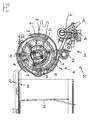
- Figur 1
- eine schematische Darstellung einer Einzelblatteingabevorrichtung gemäß der Erfindung;
- Figur 2
- eine detailliertere Darstellung des Stapelrades aus Fig 1.
Claims (7)
- Einzelblatteingabevorrichtung zur Eingabe und zur Ablage von rechteckigen Einzelblättern, insbesondere Banknoten in einem Behälter (1), mit einer Stapelradwelle (6) zur Übernahme der Einzelblätter von einer Transportbahn (4) und zur Ablage der Einzelblätter in dem Behälter (1) als horizontales Bündel, dadurch gekennzeichnet,(a) dass die Stapelradwelle (6) in axialem Abstand voneinander angeordnete Stapelräder (7) mit Kammern (8) umfasst, die an ihrem Kammerboden (12) einen Anschlag für die Einzelblätter bilden,(b) dass eine vor der Stapelradwelle (6) angeordnete Ausrichtvorrichtung bestehend aus zumindest einem Rollenpaar (15) mit einer abhebbaren Gegenrolle (16) und aus einer Ausrichtrolle (17) vorgesehen ist, die zusammen mit dem Kammerboden (12) der Stapelradwelle (6) als Anschlag ein schiefgezogenes Einzelblatt derart verschiebt, dass es mit seiner horizontalen Kante gerade in der Stapelradwelle (6) ausgerichtet ist.
- Einzelblatteingabevorrichtung nach Anspruch 1, dadurch gekennzeichnet, dass die Kammern auf dem Stapelrad (7) in einem Abstand von 120 Grad angeordnet sind.
- Einzelblatteingabevorrichtung nach Anspruch 1 oder 2, dadurch gekennzeichnet, dass auf der Stapelradwelle (6) die äußeren Stapelräder (7) eine größere Kammertiefe als die inneren Stapelräder (7) aufweisen, wobei in der Endposition das Einzelblatt am Kammerboden (12) der inneren Stapelräder (7) anstösst.
- Einzelblatteingabevorrichtung nach einem der Ansprüche 1 bis 3, dadurch gekennzeichnet, dass die Stapelradwelle (6) zumindest ein als Messrad mit Sensoren ausgebildetes Stapelrad umfasst.
- Einzelblatteingabevorrichtung nach einem der vorangehenden Ansprüche, dadurch gekennzeichnet, dass die Gegenrolle (16) elektromagnetisch abhebbar ist.
- Einzelblatteingabevorrichtung nach einem der vorangehenden Ansprüche, dadurch gekennzeichnet, dass die Ausrichtrolle (17) einen Freilauf aufweist.
- Einzelblatteingabevorrichtung nach Anspruch 1, dadurch gekennzeichnet, dass der Behälter (1) aus Kunststoff hergestellt ist und als Sicherheitsbehälter ausgebildet ist.
Applications Claiming Priority (2)
| Application Number | Priority Date | Filing Date | Title |
|---|---|---|---|
| DE10303165 | 2003-01-27 | ||
| DE10303165 | 2003-01-27 |
Publications (3)
| Publication Number | Publication Date |
|---|---|
| EP1443473A2 true EP1443473A2 (de) | 2004-08-04 |
| EP1443473A3 EP1443473A3 (de) | 2006-07-12 |
| EP1443473B1 EP1443473B1 (de) | 2007-05-23 |
Family
ID=32602973
Family Applications (1)
| Application Number | Title | Priority Date | Filing Date |
|---|---|---|---|
| EP04001413A Expired - Lifetime EP1443473B1 (de) | 2003-01-27 | 2004-01-23 | Einzelblatteingabevorrichtung |
Country Status (2)
| Country | Link |
|---|---|
| EP (1) | EP1443473B1 (de) |
| DE (2) | DE102004003289B4 (de) |
Cited By (1)
| Publication number | Priority date | Publication date | Assignee | Title |
|---|---|---|---|---|
| CN103136853A (zh) * | 2013-01-23 | 2013-06-05 | 广州广电运通金融电子股份有限公司 | 薄片类介质堆叠推送装置 |
Families Citing this family (4)
| Publication number | Priority date | Publication date | Assignee | Title |
|---|---|---|---|---|
| DE102005014290A1 (de) | 2005-03-24 | 2006-09-28 | Giesecke & Devrient Gmbh | Vorrichtung für die Ausrichtung von ungeordnetem Blattgut |
| DE102011050308A1 (de) | 2011-05-12 | 2012-11-15 | Wincor Nixdorf International Gmbh | Einwegtransportbehältnis zur Aufbewahrung von Wertscheinen und Geldkassette zur Aufnahme eines Einwegtransportbehältnisses |
| CN105678896A (zh) * | 2014-11-20 | 2016-06-15 | 浙江康越电子有限公司 | 纵向进钞点验钞机 |
| DE102021001819A1 (de) * | 2021-04-08 | 2022-10-13 | Giesecke+Devrient Currency Technology Gmbh | Elektrodenstapelrad mit Elektrodenklemmelement, Elektrodenstapelvorrichtung und Verfahren zum Erzeugen eines Elektrodenstapels |
Family Cites Families (7)
| Publication number | Priority date | Publication date | Assignee | Title |
|---|---|---|---|---|
| FR1203526A (fr) * | 1958-02-07 | 1960-01-19 | Universal Business Machines | Convoyeur de documents |
| GB2059391B (en) * | 1979-09-25 | 1983-06-22 | Laurel Bank Machine Co | Stacking paper sheets bank notes in dispensers |
| JPS61127557A (ja) * | 1984-11-28 | 1986-06-14 | Hitachi Ltd | 紙葉類集積装置 |
| DE3808624A1 (de) * | 1988-03-15 | 1989-09-28 | Nixdorf Computer Ag | Vorrichtung zur entgegennahme und geordneten ablage von einzelblaettern in einem behaelter |
| GB8819768D0 (en) * | 1988-08-19 | 1988-09-21 | Ncr Co | Sheet handling apparatus |
| ES2121027T3 (es) * | 1992-06-03 | 1998-11-16 | Mars Inc | Selector de hojas de papel rectangulares. |
| US5485989A (en) * | 1994-08-10 | 1996-01-23 | Bell & Howell Phillipsburg Company | Diverter and on-edge stacker |
-
2004
- 2004-01-22 DE DE102004003289A patent/DE102004003289B4/de not_active Expired - Fee Related
- 2004-01-23 EP EP04001413A patent/EP1443473B1/de not_active Expired - Lifetime
- 2004-01-23 DE DE502004003851T patent/DE502004003851D1/de not_active Expired - Lifetime
Cited By (1)
| Publication number | Priority date | Publication date | Assignee | Title |
|---|---|---|---|---|
| CN103136853A (zh) * | 2013-01-23 | 2013-06-05 | 广州广电运通金融电子股份有限公司 | 薄片类介质堆叠推送装置 |
Also Published As
| Publication number | Publication date |
|---|---|
| DE102004003289A1 (de) | 2004-08-12 |
| DE502004003851D1 (de) | 2007-07-05 |
| EP1443473A3 (de) | 2006-07-12 |
| DE102004003289B4 (de) | 2006-05-04 |
| EP1443473B1 (de) | 2007-05-23 |
Similar Documents
| Publication | Publication Date | Title |
|---|---|---|
| DE3889633T2 (de) | Banknotenhandhabungsvorrichtung. | |
| DE102008038771B4 (de) | Vorrichtung zum Ausrichten mindestens eines Wertscheins beim Transport entlang einer Transportstrecke | |
| DE3420336C2 (de) | Papierblatt-Ablagevorrichtung | |
| DE2717345C2 (de) | Wertscheingeber | |
| DE2506195A1 (de) | Banknotenausgabegeraet | |
| EP2586015B1 (de) | Vorrichtung zur auszahlung von wertscheinen mit einem ortsfesten auflageelement | |
| DE69510586T2 (de) | Transaktionseinrichtung mit Teile zum Speichern von Blättern | |
| DE3036001A1 (de) | Vorrichtung zum sammeln von papierblaettern, z.b. banknoten | |
| EP2190763B1 (de) | Vorrichtung für die vereinzelung von blattgut | |
| EP3080785B1 (de) | Eingabemodul und verfahren zum zuführen von wertdokumenten zu einer wertdokumentbearbeitungsvorrichtung sowie system zur bearbeitung von wertdokumenten | |
| EP1443473B1 (de) | Einzelblatteingabevorrichtung | |
| DE4202664C2 (de) | Geldscheintransport- und -sortiervorrichtung | |
| DE3834061C2 (de) | Geldausgabegerät | |
| EP2720204B1 (de) | Vorrichtung zur Handhabung von Wertscheinen | |
| DE4411403A1 (de) | Vorrichtung zum Sortieren und Stapeln von Blattgut | |
| EP2743221A1 (de) | Vorrichtung zur Handhabung von Wertscheinen mit einer einseitiger Klemmeinheit | |
| DE19609890C1 (de) | Vorrichtung zum Ändern der Transportrichtung von Einzelblättern | |
| DE102015110585A1 (de) | Vorrichtung zum linearen Wechseln einer Kanne an einer Spinnereivorbereitungsmaschine | |
| EP3376480B1 (de) | Vorrichtung zum ausrichten von wertscheinen | |
| DE3248458C2 (de) | ||
| EP3385926B1 (de) | Vorrichtung zum ausrichten von wertscheinen | |
| DE3514062A1 (de) | Wertscheingeber | |
| EP1387811B1 (de) | Vorrichtung und verfahren zur eingabe und ablage von banknoten | |
| DE102006002885B3 (de) | Vorrichtung zum stapelförmigen Ablegen von Blättern | |
| DE3100866C2 (de) |
Legal Events
| Date | Code | Title | Description |
|---|---|---|---|
| PUAI | Public reference made under article 153(3) epc to a published international application that has entered the european phase |
Free format text: ORIGINAL CODE: 0009012 |
|
| AK | Designated contracting states |
Kind code of ref document: A2 Designated state(s): AT BE BG CH CY CZ DE DK EE ES FI FR GB GR HU IE IT LI LU MC NL PT RO SE SI SK TR |
|
| AX | Request for extension of the european patent |
Extension state: AL LT LV MK |
|
| PUAL | Search report despatched |
Free format text: ORIGINAL CODE: 0009013 |
|
| AK | Designated contracting states |
Kind code of ref document: A3 Designated state(s): AT BE BG CH CY CZ DE DK EE ES FI FR GB GR HU IE IT LI LU MC NL PT RO SE SI SK TR |
|
| AX | Request for extension of the european patent |
Extension state: AL LT LV MK |
|
| 17P | Request for examination filed |
Effective date: 20060726 |
|
| GRAP | Despatch of communication of intention to grant a patent |
Free format text: ORIGINAL CODE: EPIDOSNIGR1 |
|
| AKX | Designation fees paid |
Designated state(s): DE ES FR GB IT |
|
| GRAS | Grant fee paid |
Free format text: ORIGINAL CODE: EPIDOSNIGR3 |
|
| GRAA | (expected) grant |
Free format text: ORIGINAL CODE: 0009210 |
|
| AK | Designated contracting states |
Kind code of ref document: B1 Designated state(s): DE ES FR GB IT |
|
| REG | Reference to a national code |
Ref country code: GB Ref legal event code: FG4D Free format text: NOT ENGLISH |
|
| REF | Corresponds to: |
Ref document number: 502004003851 Country of ref document: DE Date of ref document: 20070705 Kind code of ref document: P |
|
| PG25 | Lapsed in a contracting state [announced via postgrant information from national office to epo] |
Ref country code: ES Free format text: LAPSE BECAUSE OF FAILURE TO SUBMIT A TRANSLATION OF THE DESCRIPTION OR TO PAY THE FEE WITHIN THE PRESCRIBED TIME-LIMIT Effective date: 20070903 |
|
| GBT | Gb: translation of ep patent filed (gb section 77(6)(a)/1977) |
Effective date: 20070815 |
|
| ET | Fr: translation filed | ||
| PLBE | No opposition filed within time limit |
Free format text: ORIGINAL CODE: 0009261 |
|
| STAA | Information on the status of an ep patent application or granted ep patent |
Free format text: STATUS: NO OPPOSITION FILED WITHIN TIME LIMIT |
|
| 26N | No opposition filed |
Effective date: 20080226 |
|
| REG | Reference to a national code |
Ref country code: FR Ref legal event code: PLFP Year of fee payment: 13 |
|
| PGFP | Annual fee paid to national office [announced via postgrant information from national office to epo] |
Ref country code: FR Payment date: 20151208 Year of fee payment: 13 |
|
| PGFP | Annual fee paid to national office [announced via postgrant information from national office to epo] |
Ref country code: IT Payment date: 20160127 Year of fee payment: 13 Ref country code: DE Payment date: 20160119 Year of fee payment: 13 |
|
| PGFP | Annual fee paid to national office [announced via postgrant information from national office to epo] |
Ref country code: GB Payment date: 20160120 Year of fee payment: 13 |
|
| REG | Reference to a national code |
Ref country code: DE Ref legal event code: R119 Ref document number: 502004003851 Country of ref document: DE |
|
| GBPC | Gb: european patent ceased through non-payment of renewal fee |
Effective date: 20170123 |
|
| REG | Reference to a national code |
Ref country code: FR Ref legal event code: ST Effective date: 20170929 |
|
| PG25 | Lapsed in a contracting state [announced via postgrant information from national office to epo] |
Ref country code: FR Free format text: LAPSE BECAUSE OF NON-PAYMENT OF DUE FEES Effective date: 20170131 |
|
| PG25 | Lapsed in a contracting state [announced via postgrant information from national office to epo] |
Ref country code: GB Free format text: LAPSE BECAUSE OF NON-PAYMENT OF DUE FEES Effective date: 20170123 Ref country code: DE Free format text: LAPSE BECAUSE OF NON-PAYMENT OF DUE FEES Effective date: 20170801 |
|
| PG25 | Lapsed in a contracting state [announced via postgrant information from national office to epo] |
Ref country code: IT Free format text: LAPSE BECAUSE OF NON-PAYMENT OF DUE FEES Effective date: 20170123 |