EP1441069B1 - Verfahren und Vorrichtung zum Einbetten von Platten in einem eine Art von Sand enthaltendes Substrat - Google Patents
Verfahren und Vorrichtung zum Einbetten von Platten in einem eine Art von Sand enthaltendes Substrat Download PDFInfo
- Publication number
- EP1441069B1 EP1441069B1 EP20040075165 EP04075165A EP1441069B1 EP 1441069 B1 EP1441069 B1 EP 1441069B1 EP 20040075165 EP20040075165 EP 20040075165 EP 04075165 A EP04075165 A EP 04075165A EP 1441069 B1 EP1441069 B1 EP 1441069B1
- Authority
- EP
- European Patent Office
- Prior art keywords
- slab
- suction cup
- band
- vibrator
- vibrations
- Prior art date
- Legal status (The legal status is an assumption and is not a legal conclusion. Google has not performed a legal analysis and makes no representation as to the accuracy of the status listed.)
- Expired - Lifetime
Links
- 238000000034 method Methods 0.000 title claims description 70
- 239000000758 substrate Substances 0.000 title claims description 32
- 239000004576 sand Substances 0.000 title claims description 29
- 239000011148 porous material Substances 0.000 claims description 9
- 230000005540 biological transmission Effects 0.000 claims description 8
- 239000000463 material Substances 0.000 claims description 8
- 230000001419 dependent effect Effects 0.000 claims 1
- 238000005056 compaction Methods 0.000 description 7
- 239000004575 stone Substances 0.000 description 6
- 239000012530 fluid Substances 0.000 description 2
- 230000003313 weakening effect Effects 0.000 description 2
- 229910000831 Steel Inorganic materials 0.000 description 1
- 238000010276 construction Methods 0.000 description 1
- 230000000694 effects Effects 0.000 description 1
- 239000004033 plastic Substances 0.000 description 1
- 230000002265 prevention Effects 0.000 description 1
- 239000010959 steel Substances 0.000 description 1
- 238000005728 strengthening Methods 0.000 description 1
- 238000005303 weighing Methods 0.000 description 1
Images
Classifications
-
- E—FIXED CONSTRUCTIONS
- E01—CONSTRUCTION OF ROADS, RAILWAYS, OR BRIDGES
- E01C—CONSTRUCTION OF, OR SURFACES FOR, ROADS, SPORTS GROUNDS, OR THE LIKE; MACHINES OR AUXILIARY TOOLS FOR CONSTRUCTION OR REPAIR
- E01C3/00—Foundations for pavings
- E01C3/04—Foundations produced by soil stabilisation
-
- E—FIXED CONSTRUCTIONS
- E01—CONSTRUCTION OF ROADS, RAILWAYS, OR BRIDGES
- E01C—CONSTRUCTION OF, OR SURFACES FOR, ROADS, SPORTS GROUNDS, OR THE LIKE; MACHINES OR AUXILIARY TOOLS FOR CONSTRUCTION OR REPAIR
- E01C19/00—Machines, tools or auxiliary devices for preparing or distributing paving materials, for working the placed materials, or for forming, consolidating, or finishing the paving
- E01C19/52—Apparatus for laying individual preformed surfacing elements, e.g. kerbstones
- E01C19/524—Apparatus for laying individual preformed surfacing elements, e.g. kerbstones using suction devices
-
- E—FIXED CONSTRUCTIONS
- E01—CONSTRUCTION OF ROADS, RAILWAYS, OR BRIDGES
- E01C—CONSTRUCTION OF, OR SURFACES FOR, ROADS, SPORTS GROUNDS, OR THE LIKE; MACHINES OR AUXILIARY TOOLS FOR CONSTRUCTION OR REPAIR
- E01C3/00—Foundations for pavings
- E01C3/006—Foundations for pavings made of prefabricated single units
Definitions
- the invention relates to a method for at least partly embedding a slab comprising a top side and a bottom side in a substrate containing a type of sand, with the method at least comprising: placing the bottom side of the slab against the substrate.
- the invention further relates to an apparatus for at least partly embedding a slab comprising a top side and a bottom side in a substrate.
- a slab is understood to mean a slab which is, for instance, manufactured from a type of stone and/or concrete.
- the term slab also includes steel or plastic slabs. Such slabs are used in civil engineering and other construction activities. Such a slab can have a weight of some hundreds to some thousands of kilograms. The dimensions can differ from slab to slab.
- Such a method is known per se and is often used in the preparation of a ground on or over which, for instance, a traffic route is constructed.
- a truck in some cases a train, or another vehicle generating vibration when moving
- the vibrations supplied to the slab when such a vehicle is being moved over or along the slab result in a compaction of the sand present between the slabs and/or under the slab near the longitudinal edges of the slab.
- sand needs to be regularly supplied to a substrate located near a longitudinal edge or circumferential edge of the slab.
- each vibration treatment given to the slab by means of one of the above vehicles it is assessed whether the compaction of the sand under the slab has been effected to a desired extent. This may, for instance, be done by determining whether sand should be supplied to the substrate located near the longitudinal edge of the slab to compensate for the compaction of the sand present under the slab. If, after a vibration treatment, compared to a previous vibration treatment, there is no change in the substrate located near the longitudinal edge of the slab, it is assumed that the sand present near the longitudinal edges of the slab will hardly or not compact any further. If this is the case, no sand needs to be added to the substrate located near the longitudinal edge of the slab. The slab is then embedded to the desired extent.
- the drawback of a known method is that the time taken up by this method depends on the frequency at which one of the above-mentioned vibration-generating vehicles moves over or along the slab. It is possible that a train or a truck needs to be moved over or along the slab as many as five to ten times before the desired extent of embedding of the slab can be achieved. After each passing of one the above-mentioned vehicles, it needs to be examined whether sand needs to be added to compensate for the compaction of the sand under the slab. This requires manpower and time. In other words, the known method is a time-consuming and expensive method.
- the invention contemplates meeting the above-mentioned problem.
- the object of the invention is achieved by a method according to the invention which is characterized in that the method further comprises transmitting vibrations to the slab by means of a vibrator which is substantially fixated with respect to the slab.
- the slab in the substrate By means of a method according to the invention, it is possible to embed the slab in the substrate to the desired extent within a short space of time.
- the vibrations are simply transmitted from the vibrator substantially fixed with respect to the slab, to the slab.
- the sand Prior to the transmission of the vibrations or during the transmission of the vibrations to the slab, the sand can be supplied to the substrate located near the longitudinal edge of the slab.
- the time between turning on the vibrator for transmitting vibrations to the slab and turning off the vibrator can be limited to a much shorter space of time than the space of time that is needed for embedding the slab by means of the known method.
- a slab weighing 800 to 2000 kg can be embedded to the desired extent in a substrate containing a type of sand within a space of time of tens of seconds or less.
- the time needed for embedding corresponds to the time needed for a vibration-generating vehicle to be able to pass over or along the slab many times. Usually, this involves much more time than tens of seconds.
- the method according to the invention offers the advantage that the embedding of the slab can be scheduled, since it only depends on the availability of the vibrator substantially fixated with respect to the slab.
- the embedding depends on the availability of the vibration-generating vehicles for transmitting vibrations to the slab when these vehicles are moving over or along the slab. In other words, the method according to the invention is faster and less expensive.
- DE 10105587 discloses a method for embedding paving stones. Said method comprises placing a vibrating body on a top side of the paving stones and, while providing a limitation to sideways movement of the vibrating body, glidingly moving said vibrating body over the top of the paving stones.
- DE3324441 discloses a movable apparatus for transporting concrete parte, provided with at least one suction cup for lifting said concrete parts.
- the vibrations from each vibrator are transmitted to a suction cup applied against the top side of the slab.
- a suction cup applied against the top side of the slab.
- the method further comprises maintaining a vacuum in a room bounded by the slab and the suction cup.
- This makes it possible to move a very heavy slab. It is also possible to transmit vibrations to this very heavy slab via the suction cup. This is because, due to the vacuum created in the room, the slab and the suction cup will be sucked against each other such that, during the method, the slab and the suction cup can be considered a rigid whole. The vibrations transmitted from each vibrator to the suction cup will hardly be damped by the suction cup.
- the suction cup may be provided with a substantially rigid plate-shaped frame having a first side and a second side located substantially opposite the first side, the first side being provided with the at least one vibrator and the second being provided with recesses for forming the room.
- a rigid slab is eminently suitable for transmitting vibrations to the slab.
- the at least one vibrator has been provided against the first side of the frame, so that the vibrations from each vibrator are directly transmitted to the frame.
- the method also comprises preventing air from leaking into the room by means of a band provided on a circumferential edge of the second side of the frame, which band is substantially manufactured from a compressible material.
- the method may also comprise determining a depth over which the slab is embedded in the substrate.
- the determination may take place visually on the basis of a marking provided on a longitudinal edge of the slab.
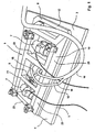
- Fig. 1 shows, in perspective, an apparatus 1 for at least partly embedding, in a substrate 2, a slab 3 manufactured from, for instance, a type of stone and/or concrete, which slab comprises a top side 4 and a bottom side 5.
- the apparatus 1 is provided with at least one suction cup 6 which, in use, is fixatable against the top side 4 of the slab 3.
- the suction cup 6 is provided with a vibrator 7 substantially fixated with respect to the suction cup 6 for, in use, transmitting vibrations to the slab 3 via the suction cup 6.
- the suction cup 6 is provided with two vibrators 7.
- the suction cup 6 is provided with means 8 for connecting a vacuum pump (not shown) by means of which, in use, a vacuum can be maintained in a room 9 bounded by the slab and suction cup 6 (see Fig. 3 and Fig. 4 ).
- the suction cup 6 is provided with a substantially rigid plate-shaped frame 10 having a first side 11 and a second side 12 located substantially opposite the first side.
- the first side 11 is provided with two vibrators 7 and the second side is provided with recesses 13 for forming the room 9 (see Fig. 3 and Fig. 4 ).
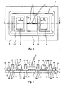
- the frame 10 comprises a frame plate 14 which is provided with plates 15 on the second side 12 of the suction cup 6 for, in use, maintaining a distance between the frame plate 14 and the slab 3 manufactured from a type of stone and/or concrete when the suction cup 6 has been applied against the slab 3. As is shown in Figs. 3 and 4 , this results in the room 9 bounded by the slab and the suction cup when the suction cup has been applied against the slab 3. It could also be said that the recesses 13 on the second side 12 of the plate-shaped frame 10 are located between the plates 15 provided against the frame plate 14.
- the frame plate 14 comprises openings 30.
- the frame 10 designed as a suction cup is provided with an air discharge connection extending from positions in the recesses 13, through the frame, to the means 8 for connecting a vacuum pump.
- the means 8 are designed as outlets to which vacuum lines 16 can be connected.
- the vacuum lines 16 form an air discharge connection between the outlets and the vacuum pump not shown.
- the outlets further have an air discharge connection through the plate-shaped frame 10 to the recesses 13, that is, in use, the rooms 9.
- the frame plate 14 is provided with perforations for obtaining the openings 30.
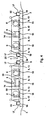
- Apparatus 1 is further provided with a band 17 provided along a circumferential edge 21 of the second side 12 of the frame 10 (see Fig. 3 and Fig. 4 ).
- the band 17 is closed upon itself and substantially manufactured from a compressible material for, in use, preventing air from leaking into the room.
- the compressible material preferably substantially contains rubber.
- the band 17 is provided with a side 18 substantially facing the slab, which side comprises pores.
- the band can be manufactured from a rubber comprising pores.
- the band 17 closed upon itself may be provided with an inside 19 and an outside 20 which each comprise a skin which substantially seals the pores (not shown).
- the frame comprises a U-section 22 extending along the circumferential edge 21 of the frame 10, in which U-section the band 17 is included.
- the band 17 is provided with a band side 18 facing the slab 3 in which recesses (not shown) have been provided. These recesses allow the compressible band to deform easily and to remain connected to the surface of the slab 3 when that surface has been provided with relief.
- the apparatus 1 is provided with two vibrators 7 substantially fixated with respect to the suction cup 6 for, in use, transmitting vibrations to the slab 3.
- the vibrators have been provided against the first side 11 of the frame 10.
- the vibrators 7 are electric vibrators.
- each vibrator is provided with an eccentric (not shown) which rotates in use for the purpose of generating the vibrations.
- the eccentrics are arranged such that, in use, they each rotate in a substantially vertically located plane. It is still more preferred that, in use, the eccentrics rotate in the same plane.
- the eccentrics preferably rotate towards each other.
- the fluid connection already discussed can also be described as an air discharge connection between the second side 12 of the plate-shaped frame 10 and the means 8 for connecting the vacuum pump.
- means are included for weakening an airflow.
- the means for weakening an airflow comprise a buffer room 23.
- the buffer room 23 is at least partly designed as a hollow beam.
- at least a part of this hollow beam extends parallel to the slab 3 in a longitudinal direction.
- the hollow beam also has a strengthening function for the plate-shaped frame. This promotes the rigidity of the plate-shaped frame.
- the hollow beams 23 are connected to one another by means of a fluid connection.
- the air to be discharged from the rooms 9 can end up in the hollow beams 23 via the perforations in the frame plate 14 and then be exhausted therefrom via the outlets 8 connected to the hollow beams 23 by and in the direction of the vacuum pump (not shown).
- the suction cup is provided with hoisting means 24 for placing the suction cup 6.
- Hoisting means may be designed such that the suction cup 6 with the slab 3 fixedly sucked against it in use can also be moved.
- the apparatus is by no means limited to the embodiment shown hereinabove.
- the apparatus may also be provided with an assembly comprising first means which, in use, have a fixed position with respect to the suction cup 6 and second means which are designed such that, in use, these second means assume a fixed position with respect to the substrate 2.
- This assembly may be designed to stop the transmission of vibrations to the suction cup 6 when the first and second means have reached a predetermined height relative to each other.
- Such an assembly may, for instance, comprise a feeler and a contact point. It is also possible for the assembly to comprise a laser and a laser light detector.
- the method for at least partly embedding a slab comprising a top side and a bottom side in a substrate containing a type of sand comprises at least placing the bottom side of the slab against the substrate and transmitting vibrations to the slab by means of a vibrator substantially fixated with respect to the slab.
- this method is carried out using the apparatus 1.
- the suction cup 6 is placed against the top side of the slab 3 such that a room 9 is formed.
- the means 8 for connecting a vacuum pump will be connected to a vacuum pump. By means of the vacuum pump, air is exhausted from the room 9. This causes the top side 4 of the slab 3 and the suction cup to be sucked against each other.
- the atmospheric pressure which is higher than the pressure of the vacuum in room 9 presses the slab and the suction cup against each other. It is then possible to place the bottom side 5 of the slab 3 against the substrate 2 by means of the hoisting means 24. Then, by means of the at least one vibrator 7 fixated with respect to the slab 3, vibrations can be transmitted to the slab 3. The vibrations from each vibrator are transmitted to the suction cup 6 applied against the top side 4 of the slab 3. The vacuum pump maintains a vacuum in the room 9 bounded by the slab 3 and the suction cup 6.
- the suction cup 6 is provided with a rigid plate-shaped frame 10 having a first side 11 and a second side 12 located substantially opposite the first side 11.
- the first side 11 is provided with the at least one vibrator 7 and the second side 12 is provided with recesses 13 for forming a room 9.
- the prevention of air leaking into the room 9 takes place by means of a band 17 provided on or along a circumferential edge 21 of the second side 12 of the frame 10, which band is manufactured substantially from a compressible material.
- a band is used as described in the description of the apparatus 1.
- the vibrators 7 are provided against the first side 11 of the frame so that the vibrations can be transmitted directly from each vibrator 7 to the suction cup 6.
- Each vibrator 7 is preferably provided with an eccentric (not shown) which rotates for the purpose of generating the vibrations.
- the eccentrics each rotate in a substantially vertical plane. A proper embedding of the slab and/or compaction of the sand present under the slab 3 takes place when the eccentrics rotate in the same plane.
- the direction of rotation of the vibrators 7 provided against the first side 11 of the frame 10 is preferably such that, looking at the top side of the slab 3, the eccentrics rotate towards each other.
- the method may further comprise: determining a depth over which the slab is embedded in the substrate. This determination may take place visually on the basis of markings provided on a longitudinal edge of the slab 3. However, it is also possible for the determination to take place by means of an assembly comprising first means having a fixed position with respect to the slab and second means having a fixed position with respect to the substrate. The assembly has been designed to stop the transmission of vibrations to the slab when the first and second means have reached a predetermined height relative to each other. Examples of such an assembly have been discussed in the description of the apparatus 1. In many cases, the bottom side 5 of the slab will be smaller than the top side 4. In other words, the slab will be provided with a sloping longitudinal edge.
- sand is provided against or near the longitudinal edge of the slab.
- the provision of sand takes place only once.
- Two slabs can be embedded such that the top sides form virtually one continuous surface.
- the sand is provided a single time on or in a joint present between the slabs. Providing the sand may be done near the arrow Z shown in Fig. 4 .
- the invention is not limited to the method shown. It is, for instance, possible for the vibrators to be provided at some distance from the first side 11 of the frame instead of directly against the first side 11 of the frame. It is then, of course, required that such a medium is present between each vibrator 7 and the first side of the frame 10 that vibration generated by each vibrator 7 can be transmitted to the frame 10 designed as a suction cup and the slab 3.
- the vibrations may be generated by means of electrically driven eccentrics, pneumatically driven eccentrics or hydraulically driven eccentrics, by rotation of the eccentrics. It is also conceivable that vibrations are generated without using eccentrics. It will be clear that, after embedding the slab 3 to a sufficient extent, the suction cup 6 is removed from the slab 3 by letting airflow into the room 9.
- the suction cup may then be removed from the slab 3 without the slab 3 changing position.
- the method can largely be carried out automatically.
- the removal of the suction cup 6 from the slab 3 can take place without manual operations by a worker stationed near the slab 3.
- Operating the vacuum, hoisting the suction cup, and operating the vibrators will have to be done by a worker.
- these operations can be carried out remotely from the slab. This promotes safety.
- adding sand to the substrate near a longitudinal edge of the slab 3 is carried out automatically.
- the method may also provide such a step.
- the apparatus may be designed such that sand can be added to the substrate located near the longitudinal edge of the slab prior to or during vibration. The supply of sand can stop automatically when it has been determined that the slab has been embedded to a sufficient extent.
Landscapes
- Engineering & Computer Science (AREA)
- Architecture (AREA)
- Civil Engineering (AREA)
- Structural Engineering (AREA)
- On-Site Construction Work That Accompanies The Preparation And Application Of Concrete (AREA)
- Hooks, Suction Cups, And Attachment By Adhesive Means (AREA)
Claims (33)
- Verfahren zum mindestens teilweise Einbetten einer Platte (3), umfassend eine obere Seite (4) und eine untere Seite (5), in ein eine Art von Sand aufweisendes Substrat (2), wobei das Verfahren mindestens umfasst:- Platzieren der unteren Seite (5) der Platte (3) gegen das Substrat (2), dadurch gekennzeichnet, dass das Verfahren aufweist:- Übertragen von Vibrationen auf die Platte (3) mit Hilfe wenigstens eines Vibrators (7), welcher bezüglich der Platte (3) im Wesentlichen fixiert ist.
- Verfahren gemäß Anspruch 1, dadurch gekennzeichnet, dass die Vibrationen jedes Vibrators (7) zu einem Saugnapf (6) übertragen werden, welcher gegen die obere Seite (4) der Platte (3) aufgebracht ist.
- Verfahren gemäß Anspruch 2, dadurch gekennzeichnet, dass das Verfahren aufweist:- Aufrechterhalten eines Vakuums in einem bezüglich der Platte (3) und des Saugnapfes (6) begrenzten Raum (9).
- Verfahren gemäß Anspruch 3, dadurch gekennzeichnet, dass der Saugnapf (6) mit einem steifen, im Wesentlichen plattenförmigen Rahmen (10) ausgestattet ist, der eine erste Seite (11) und eine zweite Seite (12) aufweist, die im Wesentlichen gegenüber der ersten Seite (11) liegt, wobei die erste Seite (11) mit dem mindestens einen Vibrator (7) ausgestattet ist und die zweite Seite (12) mit Aussparungen (13) zur Ausbildung des Raumes (9) ausgestattet ist.
- Verfahren gemäß Anspruch 4, dadurch gekennzeichnet, dass das Verfahren aufweist:- Verhindern, dass Luft in den Raum (9) austritt mit Hilfe eines Bandes (17), das auf der Umfangskante (21) der zweiten Seite des Rahmens (10) vorgesehen und im Wesentlichen aus einem zusammendrückbaren Material hergestellt ist.
- Verfahren gemäß Anspruch 5, dadurch gekennzeichnet, dass das zusammendrückbare Material im Wesentlichen Gummi aufweist.
- Verfahren gemäß Anspruch 6, dadurch gekennzeichnet, dass das Band (17) mit einer Poren aufweisenden Seite (18) im Wesentlichen der Platte (3) zugewandt vorgesehen ist.
- Verfahren gemäß Anspruch 5, 6 oder 7, dadurch gekennzeichnet, dass das Band (17) aus einem Poren aufweisenden Gummi gefertigt ist.
- Verfahren gemäß Anspruch 8, dadurch gekennzeichnet, dass das auf sich selbst geschlossene Band (17) mit einem Inneren (19) und einem Äußeren (20) ausgestattet ist, die beide eine die Poren im Wesentlichen verschließende Haut aufweisen.
- Verfahren gemäß einem der Ansprüche 5-9, dadurch gekennzeichnet, dass das Band mit einer Bandseite (18) der Platte (3) zugewandt vorgesehen ist, in welcher Aussparungen vorgesehen sind.
- Verfahren gemäß einem der vorangegangenen Ansprüche, dadurch gekennzeichnet, dass das Verfahren aufweist:- Übertragen von Vibrationen zu der Platte (3) mit Hilfe von zwei Vibratoren (7), welche bezüglich der Platte (3) im Wesentlichen fixiert sind.
- Verfahren gemäß einem der vorangegangenen Ansprüche, dadurch gekennzeichnet, dass jeder Vibrator (7) mit einem Exzenter ausgestattet ist, welcher zum Zwecke der Erzeugung von Vibrationen rotiert.
- Verfahren gemäß Anspruch 11 und 12, dadurch gekennzeichnet, dass die Exzenter jeweils in einer im Wesentlichen vertikal gelegenen Ebene rotieren.
- Verfahren gemäß Anspruch 13, dadurch gekennzeichnet, dass die Exzenter in der gleichen Ebene rotieren.
- Verfahren gemäß der Erfindung von Anspruch 12, 13 oder 14, dadurch gekennzeichnet, dass, bei Betrachtung der oberen Seite (4) der Platte (3) die Exzenter gegeneinander rotieren.
- Verfahren gemäß einem der vorangegangenen Ansprüche, dadurch gekennzeichnet, dass das Verfahren weiter aufweist: Bestimmung einer Tiefe über welche die Platte (3) in dem Substrat (2) eingebettet ist.
- Verfahren gemäß Anspruch 16, dadurch gekennzeichnet, dass die Bestimmung visuell auf Basis von Markierungen durchgeführt wird, welche auf der Längskante der Platte angeordnet sind.
- Verfahren gemäß Anspruch 16 oder 17, dadurch gekennzeichnet, dass die Bestimmung mit Hilfe einer Baugruppe durchgeführt wird, welche erste Mittel mit einer festen Position bezüglich der Platte (3) und zweite Mittel mit einer festen Position bezüglich des Substrats (2) aufweist, wobei die Baugruppe entworfen ist, um die Übertragung von Vibrationen zu der Platte (3) zu unterbrechen, wenn die ersten und zweiten Mittel eine vorbestimmte Höhe relativ zueinander erreicht haben.
- Verfahren gemäß Anspruch 18, dadurch gekennzeichnet, dass die Baugruppe einen Taster und einen Kontaktpunkt aufweist.
- Verfahren gemäß Anspruch 18 oder 19, dadurch gekennzeichnet, dass die Baugruppe einen Laser und einen Laserlichtdetektor aufweist.
- Verfahren gemäß einem der vorangegangenen Ansprüche, sofern abhängig von Anspruch 2 und 3, dadurch gekennzeichnet, dass das Platzieren der unteren Seite (5) der Platte (3) gegen das Substrat (2) durch Heben (24) und Platzieren des Saugnapfs (6) stattfindet.
- Verfahren gemäß einem der vorangegangenen Ansprüche, dadurch gekennzeichnet, dass die untere Seite (5) der Platte kleiner als die obere Seite (4) ist.
- Verfahren gemäß Anspruch 22, dadurch gekennzeichnet, dass Sand gegen oder nahe der Längskante der Platte (3) bereitgestellt ist.
- Verfahren gemäß einem der vorausgegangenen Ansprüche, dadurch gekennzeichnet, dass das Verfahren aufweist: Einbetten zweier Platten (3) so, dass die oberen Seiten (4) praktisch eine kontinuierliche Oberfläche bilden.
- Verfahren gemäß Anspruch 24, dadurch gekennzeichnet, dass Sand ein einziges Mal auf oder in einer zwischen den Platten (3) auftretenden Fuge bereitgestellt wird.
- Gerät zum mindestens teilweisen Einbetten einer Platte (3) gemäß dem Verfahren gemäß einem der Ansprüche 1-25, wobei die Platte eine obere Seite(4) und eine untere Seite (5) in einem Substrat (2) aufweist, welches eine Art von Sand enthält, das Gerät mindestens einen Vibrator (7) aufweist um im Betrieb Vibrationen zur Platte (3), dadurch gekennzeichnet, dass das Gerät mit mindestens einem Saugnapf ausgestattet ist, welcher im Betrieb gegen die obere Seite (4) der Platte (3) fixierbar ist und dass der mindestens eine Vibrator (7) bezüglich eines Saugnapfs (6) im Wesentlichen fixiert ist, um im Betrieb die Vibrationen zu der Platte (3) über den Saugnapf (6) zu übertragen.
- Gerät gemäß Anspruch 26, dadurch gekennzeichnet, dass der Saugnapf (6) mit Mitteln (8) zum Verbinden einer Vakuumpumpe ausgestattet ist, mit Hilfe derer im Betrieb ein Vakuum in einem Raum (9) aufrechterhalten wird, der durch die Platte (3)und den Saugnapf (6) begrenzt ist.
- Gerät gemäß Anspruch 26 und 27, dadurch gekennzeichnet, dass der Saugnapf (6) mit einem festen plattenförmigen Rahmen (10) ausgestattet ist, welcher eine erste Seite (11) und eine zweite Seite (12) aufweist, die im Wesentlichen gegenüber der ersten Seite liegt (11), wobei die erste Seite (11) mit dem mindestens einen Vibrator (7) ausgestattet ist und die zweite Seite (12) mit Aussparungen zur Ausbildung eines Raumes (9) ausgestattet ist.
- Gerät gemäß einem der Ansprüche 26-28, dadurch gekennzeichnet, dass das Gerät mit einem Band (17) ausgestattet ist, das entlang der Umfangskante (21) der zweiten Seite (12) des Rahmens (10) vorgesehen ist, um sich selbst geschlossen ist und im Wesentlichen aus einem zusammendrückbaren Material gefertigt ist, um Austreten der Luft in den Raum (9) zu verhindern.
- Gerät gemäß Anspruch 29, dadurch gekennzeichnet, dass das zusammendrückbare Material im Wesentlichen Gummi aufweist.
- Gerät gemäß Anspruch 29 oder 30, dadurch gekennzeichnet, dass das Band (17) mit einer Poren aufweisenden Seite (18) im Wesentlichen der Platte (3) zugewandt vorgesehen ist.
- Gerät gemäß Anspruch 29, 30 oder 31, dadurch gekennzeichnet, dass das Band (17) aus einem Poren aufweisenden Gummi gefertigt ist.
- Gerät gemäß einem der Ansprüche 29-32, dadurch gekennzeichnet, dass das auf sich selbst geschlossene Band (17) mit einem Inneren und einem Äußeren ausgestattet ist, die beide eine die Poren im Wesentlichen verschließende Haut aufweisen.
Applications Claiming Priority (2)
| Application Number | Priority Date | Filing Date | Title |
|---|---|---|---|
| NL1022419 | 2003-01-17 | ||
| NL1022419A NL1022419C2 (nl) | 2003-01-17 | 2003-01-17 | Werkwijze en inrichting voor het in een zandsoort bevattende ondergrond inbedden van een plaat. |
Publications (2)
| Publication Number | Publication Date |
|---|---|
| EP1441069A1 EP1441069A1 (de) | 2004-07-28 |
| EP1441069B1 true EP1441069B1 (de) | 2012-07-04 |
Family
ID=32589162
Family Applications (1)
| Application Number | Title | Priority Date | Filing Date |
|---|---|---|---|
| EP20040075165 Expired - Lifetime EP1441069B1 (de) | 2003-01-17 | 2004-01-19 | Verfahren und Vorrichtung zum Einbetten von Platten in einem eine Art von Sand enthaltendes Substrat |
Country Status (2)
| Country | Link |
|---|---|
| EP (1) | EP1441069B1 (de) |
| NL (1) | NL1022419C2 (de) |
Families Citing this family (2)
| Publication number | Priority date | Publication date | Assignee | Title |
|---|---|---|---|---|
| NL1025578C2 (nl) * | 2004-02-26 | 2005-09-05 | Konink Bam Groep Nv | Inrichting en werkwijze voor het plaatsen van een element op een ondergrond. |
| EP3260247B1 (de) * | 2016-06-23 | 2020-12-23 | El-Zouki Group AB | Werkzeug zur platzierung von objekten |
Family Cites Families (4)
| Publication number | Priority date | Publication date | Assignee | Title |
|---|---|---|---|---|
| DE3324441C2 (de) * | 1983-04-08 | 1986-12-18 | Reinhard Dipl.-Ing. 3070 Nienburg Göpfert | Selbstfahrende Vorrichtung zum Versetzen von Hebegut |
| DE4115464A1 (de) * | 1991-05-11 | 1992-11-12 | Schmidt Gerhard R | Verfahren zur horizontalverdichtung von boden |
| GB2356235A (en) * | 1999-11-13 | 2001-05-16 | Benford Ltd | Compactor machine |
| DE10105587C2 (de) * | 2000-06-07 | 2003-06-26 | Burkhardt Hombach | Vorrichtung und Verfahren zum Egalisieren von Pflasterungen |
-
2003
- 2003-01-17 NL NL1022419A patent/NL1022419C2/nl not_active IP Right Cessation
-
2004
- 2004-01-19 EP EP20040075165 patent/EP1441069B1/de not_active Expired - Lifetime
Also Published As
| Publication number | Publication date |
|---|---|
| NL1022419C2 (nl) | 2004-07-20 |
| EP1441069A1 (de) | 2004-07-28 |
Similar Documents
| Publication | Publication Date | Title |
|---|---|---|
| US1945145A (en) | Method of and apparatus for compacting and dewatering cementitious mixtures | |
| CA1085664A (en) | Method and apparatus for producing a ground covering from individual paving stones | |
| US3998063A (en) | Method and apparatus for removing construction piles | |
| NL1013013C2 (nl) | Werkwijze en inrichting voor het vervaardigen van schachtringen voor een tunnelbekleding. | |
| AU2011237223B2 (en) | Steel pile driving method involving degasification process | |
| EP1441069B1 (de) | Verfahren und Vorrichtung zum Einbetten von Platten in einem eine Art von Sand enthaltendes Substrat | |
| CN105829610A (zh) | 处理微粒和连接板部分 | |
| US4682912A (en) | Pipe laying apparatus | |
| JPS61501785A (ja) | 広いコンクリ−ト区域を舗装する際にコンクリ−トの水平を出すための方法および機械 | |
| KR20160023383A (ko) | 지면 다짐장치 | |
| GB2286613A (en) | Ground improvement | |
| CN211368391U (zh) | 混凝土摊铺栈桥 | |
| US2779080A (en) | Molding machine for forming concrete cribbing blocks | |
| JP6655813B2 (ja) | 鋼管杭の打撃騒音低減方法 | |
| US12486621B2 (en) | Dual ballast cribber | |
| CN112853977A (zh) | 混凝土摊铺栈桥 | |
| ATE229111T1 (de) | Verfahren zur gründung von bauwerks- oder industriestrukturen und dazugehörige vorrichtung | |
| US3426404A (en) | Block making machine | |
| JP2000024534A (ja) | コンクリート柱破砕機 | |
| NL2000599C2 (nl) | Baksteen met drager. | |
| JP6249560B2 (ja) | 地盤改良工法およびドレーン材 | |
| WO2020107060A1 (en) | Method of casting | |
| NL1025578C2 (nl) | Inrichting en werkwijze voor het plaatsen van een element op een ondergrond. | |
| EP4144920B1 (de) | Verfahren zum anordnen eines pfahls wie z. b. eines betonpfahls im boden | |
| EP3887136B1 (de) | Vereinfachtes verfahren zur harzarmierung eines steinblocks |
Legal Events
| Date | Code | Title | Description |
|---|---|---|---|
| PUAI | Public reference made under article 153(3) epc to a published international application that has entered the european phase |
Free format text: ORIGINAL CODE: 0009012 |
|
| AK | Designated contracting states |
Kind code of ref document: A1 Designated state(s): AT BE BG CH CY CZ DE DK EE ES FI FR GB GR HU IE IT LI LU MC NL PT RO SE SI SK TR |
|
| AX | Request for extension of the european patent |
Extension state: AL LT LV MK |
|
| 17P | Request for examination filed |
Effective date: 20050121 |
|
| AKX | Designation fees paid |
Designated state(s): BE DE FR NL |
|
| GRAP | Despatch of communication of intention to grant a patent |
Free format text: ORIGINAL CODE: EPIDOSNIGR1 |
|
| GRAJ | Information related to disapproval of communication of intention to grant by the applicant or resumption of examination proceedings by the epo deleted |
Free format text: ORIGINAL CODE: EPIDOSDIGR1 |
|
| GRAP | Despatch of communication of intention to grant a patent |
Free format text: ORIGINAL CODE: EPIDOSNIGR1 |
|
| GRAS | Grant fee paid |
Free format text: ORIGINAL CODE: EPIDOSNIGR3 |
|
| GRAA | (expected) grant |
Free format text: ORIGINAL CODE: 0009210 |
|
| AK | Designated contracting states |
Kind code of ref document: B1 Designated state(s): BE DE FR NL |
|
| REG | Reference to a national code |
Ref country code: DE Ref legal event code: R096 Ref document number: 602004038419 Country of ref document: DE Effective date: 20120830 |
|
| REG | Reference to a national code |
Ref country code: NL Ref legal event code: T3 |
|
| PLBE | No opposition filed within time limit |
Free format text: ORIGINAL CODE: 0009261 |
|
| STAA | Information on the status of an ep patent application or granted ep patent |
Free format text: STATUS: NO OPPOSITION FILED WITHIN TIME LIMIT |
|
| 26N | No opposition filed |
Effective date: 20130405 |
|
| BERE | Be: lapsed |
Owner name: W.O.S. SYSTEEM B.V. Effective date: 20130131 |
|
| REG | Reference to a national code |
Ref country code: DE Ref legal event code: R097 Ref document number: 602004038419 Country of ref document: DE Effective date: 20130405 |
|
| REG | Reference to a national code |
Ref country code: NL Ref legal event code: V1 Effective date: 20130801 |
|
| REG | Reference to a national code |
Ref country code: FR Ref legal event code: ST Effective date: 20130930 |
|
| PG25 | Lapsed in a contracting state [announced via postgrant information from national office to epo] |
Ref country code: NL Free format text: LAPSE BECAUSE OF NON-PAYMENT OF DUE FEES Effective date: 20130801 Ref country code: DE Free format text: LAPSE BECAUSE OF NON-PAYMENT OF DUE FEES Effective date: 20130801 Ref country code: BE Free format text: LAPSE BECAUSE OF NON-PAYMENT OF DUE FEES Effective date: 20130131 |
|
| PG25 | Lapsed in a contracting state [announced via postgrant information from national office to epo] |
Ref country code: FR Free format text: LAPSE BECAUSE OF NON-PAYMENT OF DUE FEES Effective date: 20130131 |
|
| REG | Reference to a national code |
Ref country code: DE Ref legal event code: R119 Ref document number: 602004038419 Country of ref document: DE Effective date: 20130801 |