EP1439961B1 - Image forming apparatus having position sensing device - Google Patents
Image forming apparatus having position sensing device Download PDFInfo
- Publication number
- EP1439961B1 EP1439961B1 EP02766210A EP02766210A EP1439961B1 EP 1439961 B1 EP1439961 B1 EP 1439961B1 EP 02766210 A EP02766210 A EP 02766210A EP 02766210 A EP02766210 A EP 02766210A EP 1439961 B1 EP1439961 B1 EP 1439961B1
- Authority
- EP
- European Patent Office
- Prior art keywords
- print device
- image forming
- forming apparatus
- sensor
- pens
- Prior art date
- Legal status (The legal status is an assumption and is not a legal conclusion. Google has not performed a legal analysis and makes no representation as to the accuracy of the status listed.)
- Expired - Lifetime
Links
- 238000010304 firing Methods 0.000 description 17
- 238000010586 diagram Methods 0.000 description 7
- 238000004519 manufacturing process Methods 0.000 description 4
- 230000007246 mechanism Effects 0.000 description 3
- 238000000034 method Methods 0.000 description 3
- 230000007423 decrease Effects 0.000 description 2
- 239000000463 material Substances 0.000 description 2
- 229920002799 BoPET Polymers 0.000 description 1
- 239000005041 Mylar™ Substances 0.000 description 1
- 230000001133 acceleration Effects 0.000 description 1
- 238000007792 addition Methods 0.000 description 1
- 230000002411 adverse Effects 0.000 description 1
- 230000015572 biosynthetic process Effects 0.000 description 1
- 238000004140 cleaning Methods 0.000 description 1
- 239000000428 dust Substances 0.000 description 1
- 230000000694 effects Effects 0.000 description 1
- 230000003993 interaction Effects 0.000 description 1
- 238000012986 modification Methods 0.000 description 1
- 230000004048 modification Effects 0.000 description 1
- 230000008569 process Effects 0.000 description 1
- 238000001429 visible spectrum Methods 0.000 description 1
Images

Classifications
-
- B—PERFORMING OPERATIONS; TRANSPORTING
- B41—PRINTING; LINING MACHINES; TYPEWRITERS; STAMPS
- B41J—TYPEWRITERS; SELECTIVE PRINTING MECHANISMS, i.e. MECHANISMS PRINTING OTHERWISE THAN FROM A FORME; CORRECTION OF TYPOGRAPHICAL ERRORS
- B41J19/00—Character- or line-spacing mechanisms
- B41J19/18—Character-spacing or back-spacing mechanisms; Carriage return or release devices therefor
- B41J19/20—Positive-feed character-spacing mechanisms
- B41J19/202—Drive control means for carriage movement
- B41J19/205—Position or speed detectors therefor
- B41J19/207—Encoding along a bar
Definitions
- the present disclosure relates to an image forming apparatus and, more specifically, to an image forming apparatus having a position sensing device.
- Image forming apparatus are used to form text and graphic images on a variety of print media including, but not limited to, paper; card stock, mylar and transparency slock.
- Certain image forming apparatus include a print device that consists of a scanning carriage and one or more printing elements.
- the scanning carriage will traverse back and forth over the surface of the print media along the scan axis.
- a controller causes the printing element(s) to print at positions intended to result in portions of the desired image.
- the print media is periodically advanced along the media axis, which is transverse to that of the movement scanning carriage, so that the image may be completed.
- an image forming apparatus with this type of print device is an ink jet printer.
- the pens often include a printhead with a plurality of ink ejecting nozzles arranged in a two-dimensional array of rows and columns that print individual ink spots (or "drops") as the carriage scans across the media.
- a 600 dpi (dots-per-inch (25.4 mm)) printhead with a 12.7mm (1 ⁇ 2 inch) swath will, for example, typically have two columns with 150 nozzles in each column.
- Ink drops are fired through the nozzles by an ink ejection mechanism, such as a piezo-electric or thermal ejection mechanism, to create the desired dot pattern (or "image").
- the ability to accurately track the position of the printing elements as the scanning carriage moves along the scan axis is typically important, regardless of the type of printing element that is carried by the carriage, because position data is used to more accurately control the printing process and reduce dot placement and other printing errors.
- a linear encoder strip and sensor arrangement are frequently used for this purpose.
- the encoder strip which includes a series of graduations, is mounted in parallel with the scan axis and the sensor, such as a light source and detector, is carried by the carriage in close proximity to the encoder strip.
- Position information from the encoder strip and sensor arrangement is used to control actuation of the printing element and, in the case of an ink jet printer pen, the firing of individual nozzles on the pens.
- Position information may also be used to control carriage movement
- the accuracy of a conventional encoder strip and senor arrangement decreases as the distance between the sensor and the printing element increases because the relative positions of the printing elements and sensor do not remain constant during a printing operation. This is due to the fad that there is typically some "slop" in the bearings that support the scanning carriage and some flexure of the carriage as it moves along the scan axis.
- the distance between some of the printing elements and the sensor can be relatively large, which adversely effects the positional accuracy of those printing elements by increasing the likelihood of dot ptacernent errors.
- the same problems may be encountered when relatively tall printing elements (i.e.
- the distance between the sensor and certain portions of the relatively tall printing element may be large enough to result in erroneous position data for those portions and dot placement or, possibly, other printing errors.
- WO 96/14989 The purpose in WO 96/14989 is to reduce errors due to variations in the markings of the encoder strip along its length.
- JP 08 282048 the purpose is for one sensor to back the other up, so that if the first sensor cannot make a reading, e.g. because of dust on the encoder strip, then the reading of the second sensor is used and vice versa.
- An apparatus that senses the position of at least two locations on a movable print device may be provided in accordance with one embodiment of a present invention.
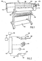
- an image forming apparatus 100 in accordance with one embodiment of a present invention includes a housing 102 and a movable print device 104.
- the position of the print device 104 is monitored by a sensor system 106 which preferably includes a device having indicia that can be sensed, such as an encoder strip 108 with visible graduations, and at least two sensors 110a and 110b.
- the sensor system 106 is discussed in greater detail below.
- the exemplary housing 102 is provided with end portions 112 and 114, a window 116, a cover 118 that covers a print media roll (not shown), a receiving bin 120 and a shelf 122.
- the housing end portion 112 preferably encloses a scanning motor 124 that drives print device 104 back and forth over the print media 126 and a plurality of pen refill stations (not shown).
- the print media 126 is pulled though a slot 128 and carried by a roller 130 that is driven by a motor 132 in conventional fashion.
- the motor 132 and a printing element cleaning station (not shown) are located within the housing end portion 114.
- a control panel 134 including a display 136 and control buttons 138, is preferably supported on the exterior of the housing end portion 114.
- the print device 104, sensor system 106, motors 124 and 132, and control panel 134 are connected to a printer controller 140 in conventional fashion in the exemplary embodiment.
- Suitable printer controllers include, for example, microprocessor based controllers.
- a clock 141 provides time information to the controller 140 which, when combined with position information from the sensor system 106, may be used to calculate the velocity and acceleration of the print device 104, which may in turn be used by the controller as it controls the operation of the print device.
- the printer controller 140 receives image data from, for example, an application program, position data from the sensor system 106 and time information from the clock 141 as it controls the operation of the print device 104 and motors 124 and 132 to produce an image that corresponds to the image data. Additional aspects of the operation of the exemplary printer controller 140 are discussed in greater detail below.
- the print device 104 in the exemplary image forming apparatus 100 includes a plurality of printing elements.
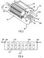
- the print device 104 is provided with a plurality of ink jet pens 142 (sometimes referred to as “printhead cartridges,” “pen cartridges” and “print cartridges”) that are carried by a scanning carriage 144 in a formation referred to herein as a "bank.”
- the pens 142 may, for example, be of the readily removable type that include a self-contained ink reservoir, the type that carry a small amount of ink and are refilled by tubes that connect the pens to a remote ink reservoir (in what is sometimes referred to as an "off-axis" system), or the type that are periodically moved to the remote ink reservoirs where they are filled (in what is sometimes referred to as a "take a gulp" system).
- a suitable pen for use in the exemplary embodiment is the Hewlett Packard Model No. C1806A pen for large format printers such as the aforementioned Hewlett Packard DesignJet 2500 Series printers.
- Such pens include nozzle plates 143 ( Figure 5) with two columns of 124 nozzles (248 total nozzles).
- the exemplary embodiment illustrated in Figures 1-4 includes eight pens in a single bank.
- the number of pens 142 in a single bank can, however, vary from one to twelve, or even more if applications so require.
- the banks may be arranged such that each pen is aligned with the other pens (as shown), or such that one or more of the pens in the bank is offset (or "staggered") in the media axis from one or more of the other pens.
- the pens 142 may be arranged such that the nozzle columns are either parallel to the media scan axis or diagonal to the media scan axis.
- the exemplary scanning carriage 144 which reciprocatingly slides (or scans) on slide bearings back and forth along slider rods 146a and 146b ( Figure 3) to define the carriage scan axis, consists primarily of a main body 148 having a plurality of pen slots 149 that respectively receive the pens 142.
- a pivotable latch 150 may be used to hold the pens 142 in place.
- a rear tray 152 carries electronic devices such as a pen interface printed circuit board. The electronic devices may also be mounted vertically or in other orientations.
- the scanning motor 124 is connected to the scanning carriage 144 in the exemplary embodiment by a drive belt 154 in conventional fashion. Other mechanisms for driving a scanning carriage, such as a motor and cable arrangement or linear motor, may be used if desired.
- the exemplary image forming apparatus 100 includes a sensor system 106 that consists of a transparent linear encoder strip 108 and a pair of sensors 110a and 110b. More specifically, the graduations are sensed as the scanning carriage 144 moves to determine the position of the scanning carriage on the scan axis.
- a suitable sensor is a conventional light source and light sensor arrangement where light from the source is directed through the encoder strip and sensed by the sensor on the other side of the encoder strip.
- the position data based on the number of graduations sensed as the scanning carriage 144 moves away from its home location, is used to determine the pen nozzle firing times (i.e.
- the sensors 110a and 110b are located at the longitudinal ends of the scanning carriage 144 within respective sensor housings 156 (only one visible) and as close to the adjacent pens 142 as practicable.
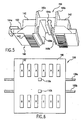
- the data from sensor 110a is used to control the nozzle firing times of the four closest pens 142, i.e. those identified with an "A" in Figure 4, while the data from sensor 110b is used to control the nozzle firing times of the other four pens, i.e. those identified with a "B.”
- Position data from either one of the sensors 110a and 110b may be used in conventional fashion, with time information from the clock 141, for carriage motion control purposes.
- data from the sensors 110a and 110b is combined and the controller 140 interpolates (and extrapolates, if necessary) positional data for locations between (or beyond) the sensors. Positional data for the location of each pen 142 is interpolated and used to individually control the firing the pens.
- the sensors 110a and 110b may be reheated in order to further reduce the distance between the sensors and the associated pens 142 or other printing elements.
- the sensors 110a and 110b may be moved to the dash line positions shown in Figure 4.
- the number of sensors 110a and/or 110b may also vary depending on the configuration of the associated scanning carriage, the size, number and type of pens (or other printing elements), and the desired level of printing accuracy as measured by, for example, dot placement error.
- Each pen could even have its own corresponding sensor if an application so required or, as described below with reference to Figure 8, a single pen could have more than one sensor associated therewith.
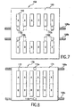
- a print device 158 in accordance with another preferred embodiment includes two banks of pen slots with nozzle plate openings that allow the nozzle plates 143 to face the print media.
- the print device 158 may be reciprocatingly driven back and forth over print media by a motor and bell arrangement in the manner described above.
- the pens 142 are supported on a scanning carriage 160 that, in the exemplary embodiment, includes a main body 162 with two banks of six pen slots and a pair of slide bearings 164a and 164b that allow the carriage to slide along a pair of rails (not shown).
- Two pen interface printed circuit boards 166a and 166b, i.e. one for each pen bank, are also provided.
- the scanning carriage 160 in the exemplary embodiment illustrated in Figures 5 and 6 is preferably employed in image forming apparatus including sensor systems having at least two encoder strips 108a and 108b and at least two sensors 110a and 110b. To that end, the encoder strips 108a and 108b pass through a pair of sensor housings 168a and 168b that are positioned adjacent to the pen banks.
- the data from sensor 110a is used to control the nozzle firing times of the pens 142 identified with an "A" in Figure 6 and the data from sensor 110b is used to control the nozzle firing times of the pens identified with a "B.”
- the sensors 110a and 110b are preferably positioned at the midpoint of each bank of pens 142 in order to minimize the distance between the sensors and the farthest pens therefrom.
- a print device 158' that is otherwise identical to print device 158 is provided with four sensors 110a, 110b, 110c and 110d in order to further increase dot placement accuracy.
- the data from sensor 110a is used to control the nozzle firing times of the pens 142 identified with an "A”
- the data from sensor 110b is used to control the nozzle firing times of the pens identified with a "B”
- the data from sensor 110c is used to control the nozzle firing times of the pens 142 identified with an "C”
- the data from sensor 110d is used to control the nozzle firing times of the pens identified with a "D.”
- an exemplary print device 170 may include one or more pens 172 or other printing elements on a carriage 174.
- the pens 172 are relatively tall and print a relatively tall swath (i.e. typically greater than one inch).
- the exemplary print device 170 includes a sensor system consisting of at least two encoder strips 108a and 108b and at least two sensors 110a and 110b.
- the encoder strips 108a and 108b pass through a pair of sensor housings similar to those discussed above with reference to Figure 5 and are positioned adjacent to the mid-line of the pen bank.
- the sensors 110a and 110b are associated with particular nozzles, as opposed to particular pens. More specifically, data from sensor 110a is used to control the firing times of the nozzles in the portions of the pens 172 identified with an "A" and data from sensor 110b is used to control the firing times of the nozzles in the portions of the pens identified with a "B.”
- the positions of two or more locations on a movable print device may be monitored using devices other than encoder-based sensor systems.
- one or more sensor devices are provided within the image forming apparatus and one or more fiducial reference points on the print device facilitate the sensing of position at two different locations on the print device.
- the fiducial reference points may be additional devices (i.e. "cooperative elements") mounted on the print device or readily identifiable portions of the print device itself such as shiny brackets.
- an exemplary print device 176 may include one or more pens 142 or other printing elements on a carriage 178. Movement of the print device 176 is sensed by a laser interferometer system.
- the laser interferometer system includes a pair of light source and sensor devices 180a and 180b that are mounted within the associated printing apparatus, preferably at one end of the scan axis, and a pair of reflectors 182a and 182b, preferably mirrors, that are carried in spaced relation on the carriage 178 and act as the fiducial reference points.
- the reflectors 182a and 182b may be located on the top, bottom or sides or the carriage 178.
- Light beams including all suitable electromagnetic energy both in and out of the visible spectrum, emitted by the source and sensor devices 180a and 180b are reflected by the reflectors 182a and 182b back to the source and sensor devices in the manner illustrated in Figure 9 to individually determine how far the reflectors have moved from their respective original home locations.
- Data from sensor 180a is used to control the nozzle firing times of the pens 142 identified with an "A” and data from sensor 180b is used to control the nozzle firing times of the pens identified with a "B.”
- Additional source and sensor devices and reflectors may be provided as applications require.
- the individual source and sensor devices 180a and 180b may be incorporated into a single device capable of providing and sensing more than one light beam and the individual spaced reflectors 182a and 182b may be incorporated into a single component capable of reflecting light from two different locations on the print device.
- the print device 184 illustrated in Figure 10 includes a carriage 186 that supports two banks of six pen 142.
- a pair of light source and sensor devices 180a and 180b are mounted within the associated printing apparatus and a pair of reflectors 182a and 182b are carried in spaced relation on the carriage 186.
- Data from sensor 180a is used to control the nozzle firing times of the pens 142 identified with an "A" and data from sensor 180b is used to control the nozzle firing times of the pens identified with a "B.”
- obtaining position data at more than one location on a movable print device reduces the distance between respective portions of the print device and the associated sensor, thereby increasing the accuracy of the print device and reducing the likelihood of dot placement or other errors.
- Obtaining position data at more than one location on a movable print device also allows print devices that are manufactured with lower tolerances, lower cost materials and/or simplified manufacturing processes to achieve the same dot placement accuracy as those manufactured with tighter tolerances, higher cost materials and/or more complicated manufacturing processes.
- position data from one or more other position sensing subsystems can be used to continue operation, albeit at a reduced level of performance.
- relatively tall swaths may be formed using a print device that aligns two or more pens or other printing elements end to end instead of the relatively tall pen described above with reference to Figure 8.
- the present embodiments are also susceptible to use with a wide variety of sensors in addition to those described above and are not limited to encoder-based and laser interferometer systems.
- Other suitable sensor systems include photo-reflective encoder strip systems, magnetic encoder strip systems, triangulation sensor systems, magnetostrictive sensor systems, ultrasonic sensor systems, cable extension transducer systems, linear variable differential transformer systems, and digital camera systems.
- sensors and/or fiducial reference points may be carried by some or all of the pens themselves, instead of being carried by the carriage.
- this disclosure has revealed an image forming apparatus having a position sensing device independently sensing the position of at least two locations on a movable print device.
Landscapes
- Ink Jet (AREA)
- Accessory Devices And Overall Control Thereof (AREA)
- Character Spaces And Line Spaces In Printers (AREA)
Applications Claiming Priority (5)
| Application Number | Priority Date | Filing Date | Title |
|---|---|---|---|
| US4434 | 1987-01-20 | ||
| US10/000,829 US6616263B2 (en) | 2001-10-31 | 2001-10-31 | Image forming apparatus having position monitor |
| US829 | 2001-10-31 | ||
| US10/004,434 US6652061B2 (en) | 2001-10-31 | 2001-10-31 | Image forming apparatus having position sensing device |
| PCT/US2002/027927 WO2003037638A1 (en) | 2001-10-31 | 2002-08-28 | Image forming apparatus having position sensing device |
Publications (2)
| Publication Number | Publication Date |
|---|---|
| EP1439961A1 EP1439961A1 (en) | 2004-07-28 |
| EP1439961B1 true EP1439961B1 (en) | 2006-01-18 |
Family
ID=26668208
Family Applications (1)
| Application Number | Title | Priority Date | Filing Date |
|---|---|---|---|
| EP02766210A Expired - Lifetime EP1439961B1 (en) | 2001-10-31 | 2002-08-28 | Image forming apparatus having position sensing device |
Country Status (7)
| Country | Link |
|---|---|
| US (1) | US6910753B2 (OSRAM) |
| EP (1) | EP1439961B1 (OSRAM) |
| JP (1) | JP2005507799A (OSRAM) |
| CN (1) | CN100333922C (OSRAM) |
| DE (1) | DE60208805T2 (OSRAM) |
| TW (1) | TW568836B (OSRAM) |
| WO (1) | WO2003037638A1 (OSRAM) |
Families Citing this family (6)
| Publication number | Priority date | Publication date | Assignee | Title |
|---|---|---|---|---|
| US20040161481A1 (en) * | 2002-12-18 | 2004-08-19 | Algorx | Administration of capsaicinoids |
| JP4976117B2 (ja) * | 2006-12-11 | 2012-07-18 | ニスカ株式会社 | 印刷装置 |
| JP5477042B2 (ja) * | 2010-02-23 | 2014-04-23 | コニカミノルタ株式会社 | インクジェット記録装置 |
| CN102275723A (zh) * | 2011-05-16 | 2011-12-14 | 天津工业大学 | 一种基于机器视觉的输送带在线监测系统和方法 |
| JP5976048B2 (ja) * | 2014-07-17 | 2016-08-23 | 京セラドキュメントソリューションズ株式会社 | インクジェット記録装置 |
| JP7555022B2 (ja) * | 2020-05-19 | 2024-09-24 | パナソニックIpマネジメント株式会社 | インクジェット印刷装置 |
Family Cites Families (14)
| Publication number | Priority date | Publication date | Assignee | Title |
|---|---|---|---|---|
| JP3049663B2 (ja) * | 1991-02-20 | 2000-06-05 | キヤノン株式会社 | 記録装置及び記録方法 |
| US5289208A (en) * | 1991-10-31 | 1994-02-22 | Hewlett-Packard Company | Automatic print cartridge alignment sensor system |
| US5352984A (en) * | 1992-11-04 | 1994-10-04 | Cable Repair Systems Corporation | Fault and splice finding system and method |
| US5617122A (en) * | 1992-12-10 | 1997-04-01 | Canon Kabushiki Kaisha | Recording apparatus and method for controlling recording head driving timing |
| EP0622239B1 (en) * | 1993-04-30 | 1998-08-26 | Hewlett-Packard Company | Multiple ink jet print cartridge alignment system |
| WO1996014989A2 (en) * | 1994-11-10 | 1996-05-23 | Lasermaster Corporation | Large format ink jet printer and ink supply system |
| JPH08282048A (ja) * | 1995-04-14 | 1996-10-29 | Copyer Co Ltd | 画像形成装置 |
| US6144721A (en) * | 1996-01-05 | 2000-11-07 | Communications Technology Corporation | Apparatus and method for line pair testing and fault diagnostics |
| US5992969A (en) * | 1996-05-30 | 1999-11-30 | Hewlett-Packard Company | Position encoding system and method using a composite codestrip |
| US6206512B1 (en) * | 1999-01-29 | 2001-03-27 | Hewlett-Packard Company | Replaceable ink delivery tube system for large format printer |
| US6019454A (en) * | 1997-03-04 | 2000-02-01 | Hewlett-Packard Company | Multipass inkjet printmodes with randomized dot placement, to minimize patterning and liquid loading |
| US6247802B1 (en) * | 1999-01-29 | 2001-06-19 | Hewlett-Packard Company | Ink supply tube guiding system for large format printer |
| US6232594B1 (en) * | 1999-06-22 | 2001-05-15 | Hewlett-Packard Company | Feedback control system using optical incremental position encoder with dual sinusoidal intensity patterns |
| US6616263B2 (en) * | 2001-10-31 | 2003-09-09 | Hewlett-Packard Development Company, L.P. | Image forming apparatus having position monitor |
-
2002
- 2002-08-28 DE DE60208805T patent/DE60208805T2/de not_active Expired - Lifetime
- 2002-08-28 EP EP02766210A patent/EP1439961B1/en not_active Expired - Lifetime
- 2002-08-28 WO PCT/US2002/027927 patent/WO2003037638A1/en not_active Ceased
- 2002-08-28 CN CNB028216555A patent/CN100333922C/zh not_active Expired - Fee Related
- 2002-08-28 JP JP2003539950A patent/JP2005507799A/ja active Pending
- 2002-09-04 TW TW091120209A patent/TW568836B/zh not_active IP Right Cessation
-
2003
- 2003-05-21 US US10/442,445 patent/US6910753B2/en not_active Expired - Lifetime
Also Published As
| Publication number | Publication date |
|---|---|
| CN100333922C (zh) | 2007-08-29 |
| US20030202030A1 (en) | 2003-10-30 |
| WO2003037638A1 (en) | 2003-05-08 |
| DE60208805D1 (de) | 2006-04-06 |
| CN1578734A (zh) | 2005-02-09 |
| DE60208805T2 (de) | 2006-08-31 |
| US6910753B2 (en) | 2005-06-28 |
| EP1439961A1 (en) | 2004-07-28 |
| JP2005507799A (ja) | 2005-03-24 |
| TW568836B (en) | 2004-01-01 |
Similar Documents
| Publication | Publication Date | Title |
|---|---|---|
| US6616263B2 (en) | Image forming apparatus having position monitor | |
| EP0863004B2 (en) | Dynamic multi-pass print mode corrections to compensate for malfunctioning inkjet nozzles | |
| JP3514508B2 (ja) | インクジェット・カートリッジの整列用基準パターン | |
| US6652061B2 (en) | Image forming apparatus having position sensing device | |
| US6457806B2 (en) | Ink-jet print pass microstepping | |
| JP3417657B2 (ja) | 多色インクジェット・プリントカートリッジのオフセット修正装置及び方法 | |
| EP0242083B1 (en) | Compact plotter for generation of accurate plotted images of long length | |
| EP0622237B1 (en) | Phase plate design for aligning multiple ink jet cartridges by scanning a reference pattern | |
| US5448269A (en) | Multiple inkjet cartridge alignment for bidirectional printing by scanning a reference pattern | |
| EP1257422B1 (en) | Ink jet print head having offset nozzle arrays | |
| US5777638A (en) | Print mode to compensate for microbanding | |
| JP2001162808A (ja) | 基体前進制御を有する方法およびプリンタ | |
| EP1439961B1 (en) | Image forming apparatus having position sensing device | |
| EP1057647B1 (en) | Ink jet printer | |
| US7367646B2 (en) | Test card for ink jet printers and method of using same | |
| US6896355B2 (en) | Printhead positioning mechanism | |
| JP3330342B2 (ja) | ドットプリンタおよびドットプリンタの制御方法 | |
| JP4976117B2 (ja) | 印刷装置 | |
| JP4250901B2 (ja) | インクジェット記録装置のヘッド駆動補正方法 | |
| JP2023080961A (ja) | システムおよび記録装置 | |
| JP2022152188A (ja) | インクジェット記録装置および記録方法 | |
| JP2000168151A (ja) | 記録装置 | |
| JPH08123804A (ja) | 記録システム |
Legal Events
| Date | Code | Title | Description |
|---|---|---|---|
| PUAI | Public reference made under article 153(3) epc to a published international application that has entered the european phase |
Free format text: ORIGINAL CODE: 0009012 |
|
| 17P | Request for examination filed |
Effective date: 20040423 |
|
| AK | Designated contracting states |
Kind code of ref document: A1 Designated state(s): AT BE BG CH CY CZ DE DK EE ES FI FR GB GR IE IT LI LU MC NL PT SE SK TR |
|
| AX | Request for extension of the european patent |
Extension state: AL LT LV MK RO SI |
|
| 17Q | First examination report despatched |
Effective date: 20041015 |
|
| GRAP | Despatch of communication of intention to grant a patent |
Free format text: ORIGINAL CODE: EPIDOSNIGR1 |
|
| GRAS | Grant fee paid |
Free format text: ORIGINAL CODE: EPIDOSNIGR3 |
|
| GRAA | (expected) grant |
Free format text: ORIGINAL CODE: 0009210 |
|
| AK | Designated contracting states |
Kind code of ref document: B1 Designated state(s): DE FR GB |
|
| REG | Reference to a national code |
Ref country code: GB Ref legal event code: FG4D |
|
| REF | Corresponds to: |
Ref document number: 60208805 Country of ref document: DE Date of ref document: 20060406 Kind code of ref document: P |
|
| ET | Fr: translation filed | ||
| PLBE | No opposition filed within time limit |
Free format text: ORIGINAL CODE: 0009261 |
|
| STAA | Information on the status of an ep patent application or granted ep patent |
Free format text: STATUS: NO OPPOSITION FILED WITHIN TIME LIMIT |
|
| 26N | No opposition filed |
Effective date: 20061019 |
|
| REG | Reference to a national code |
Ref country code: GB Ref legal event code: 732E Free format text: REGISTERED BETWEEN 20120329 AND 20120404 |
|
| REG | Reference to a national code |
Ref country code: FR Ref legal event code: PLFP Year of fee payment: 15 |
|
| REG | Reference to a national code |
Ref country code: FR Ref legal event code: PLFP Year of fee payment: 16 |
|
| REG | Reference to a national code |
Ref country code: FR Ref legal event code: PLFP Year of fee payment: 17 |
|
| PGFP | Annual fee paid to national office [announced via postgrant information from national office to epo] |
Ref country code: GB Payment date: 20180720 Year of fee payment: 17 |
|
| PGFP | Annual fee paid to national office [announced via postgrant information from national office to epo] |
Ref country code: FR Payment date: 20181207 Year of fee payment: 18 |
|
| PGFP | Annual fee paid to national office [announced via postgrant information from national office to epo] |
Ref country code: DE Payment date: 20181207 Year of fee payment: 18 |
|
| GBPC | Gb: european patent ceased through non-payment of renewal fee |
Effective date: 20190828 |
|
| PG25 | Lapsed in a contracting state [announced via postgrant information from national office to epo] |
Ref country code: GB Free format text: LAPSE BECAUSE OF NON-PAYMENT OF DUE FEES Effective date: 20190828 |
|
| REG | Reference to a national code |
Ref country code: DE Ref legal event code: R119 Ref document number: 60208805 Country of ref document: DE |
|
| PG25 | Lapsed in a contracting state [announced via postgrant information from national office to epo] |
Ref country code: FR Free format text: LAPSE BECAUSE OF NON-PAYMENT OF DUE FEES Effective date: 20200831 Ref country code: DE Free format text: LAPSE BECAUSE OF NON-PAYMENT OF DUE FEES Effective date: 20210302 |