EP1439670A2 - Verfahren und System zur Parametisierung von Buskomponenten - Google Patents
Verfahren und System zur Parametisierung von Buskomponenten Download PDFInfo
- Publication number
- EP1439670A2 EP1439670A2 EP03025582A EP03025582A EP1439670A2 EP 1439670 A2 EP1439670 A2 EP 1439670A2 EP 03025582 A EP03025582 A EP 03025582A EP 03025582 A EP03025582 A EP 03025582A EP 1439670 A2 EP1439670 A2 EP 1439670A2
- Authority
- EP
- European Patent Office
- Prior art keywords
- vehicle
- bus
- control unit
- blower
- climate control
- Prior art date
- Legal status (The legal status is an assumption and is not a legal conclusion. Google has not performed a legal analysis and makes no representation as to the accuracy of the status listed.)
- Granted
Links
Images


Classifications
-
- B—PERFORMING OPERATIONS; TRANSPORTING
- B60—VEHICLES IN GENERAL
- B60H—ARRANGEMENTS OF HEATING, COOLING, VENTILATING OR OTHER AIR-TREATING DEVICES SPECIALLY ADAPTED FOR PASSENGER OR GOODS SPACES OF VEHICLES
- B60H1/00—Heating, cooling or ventilating [HVAC] devices
- B60H1/00642—Control systems or circuits; Control members or indication devices for heating, cooling or ventilating devices
- B60H1/0073—Control systems or circuits characterised by particular algorithms or computational models, e.g. fuzzy logic or dynamic models
-
- H—ELECTRICITY
- H04—ELECTRIC COMMUNICATION TECHNIQUE
- H04L—TRANSMISSION OF DIGITAL INFORMATION, e.g. TELEGRAPHIC COMMUNICATION
- H04L12/00—Data switching networks
- H04L12/28—Data switching networks characterised by path configuration, e.g. LAN [Local Area Networks] or WAN [Wide Area Networks]
- H04L12/40—Bus networks
- H04L12/403—Bus networks with centralised control, e.g. polling
-
- H—ELECTRICITY
- H04—ELECTRIC COMMUNICATION TECHNIQUE
- H04L—TRANSMISSION OF DIGITAL INFORMATION, e.g. TELEGRAPHIC COMMUNICATION
- H04L12/00—Data switching networks
- H04L12/28—Data switching networks characterised by path configuration, e.g. LAN [Local Area Networks] or WAN [Wide Area Networks]
- H04L12/40—Bus networks
- H04L2012/40208—Bus networks characterized by the use of a particular bus standard
- H04L2012/40234—Local Interconnect Network LIN
-
- H—ELECTRICITY
- H04—ELECTRIC COMMUNICATION TECHNIQUE
- H04L—TRANSMISSION OF DIGITAL INFORMATION, e.g. TELEGRAPHIC COMMUNICATION
- H04L12/00—Data switching networks
- H04L12/28—Data switching networks characterised by path configuration, e.g. LAN [Local Area Networks] or WAN [Wide Area Networks]
- H04L12/40—Bus networks
- H04L2012/40267—Bus for use in transportation systems
- H04L2012/40273—Bus for use in transportation systems the transportation system being a vehicle
Definitions
- the invention relates to a method for parameterization of bus components acting as program-controlled slave units through a bus system with a master-slave structure can connect to a master unit, and also a system for parameterizing components of a Motor vehicle interior air conditioning system-forming slave units, the as program-controlled bus components through a bus system, e.g. a LIN bus because of one corresponding bus data protocol with a master unit functioning program-controlled vehicle climate control unit communicate.
- a bus system e.g. a LIN bus because of one corresponding bus data protocol with a master unit functioning program-controlled vehicle climate control unit communicate.
- Process control is currently also used in motor vehicles program-controlled electronic components in bus networks Systems used.
- An example of this is the Motor vehicle interior air conditioning, in which a program-controlled Vehicle climate control unit with program-controlled Blower controllers, actuators and sensor units communicates via a LIN bus.
- the Bus components at the end of the line i.e. after completing the full Equipment of the motor vehicle with the interior air conditioning system parameterized. This made one Adaptation to the vehicle-specific properties performed.
- This has the disadvantage that e.g. in spare parts logistics from the workshops the bus components vehicle-specific kept in stock or in the workshop had to be programmed.
- Device protection functions such as e.g. Motor current limitation, power limitation and / or temperature limitation with air conditioning fans of the vehicle interior air conditioning only specified statically.
- Such protective functions are in previous vehicle interior air conditioning systems designed to fit in the vehicle all permissible environmental conditions, such as vehicle condition, Tolerance, do not respond. This means that for different Vehicle types different static protection functions specified and the blower motors, the auxiliary heating systems and the control units assigned to them frequently had to be oversized.
- the essential aspect of the method according to the invention is the introduction of a parameterization step by the individual parameters for the bus components from the master unit be programmed.
- This parameterization step takes place within the data protocol of the master-slave bus system, e.g. LIN bus system, for every bus component once or depending on the system configuration repeatedly and / or cyclically.
- the bus components only when they are installed or replaced be transmitted. This means that no end of tape or variant programming is required be made. It can be cross-vehicle identical bus components manufactured through the parameterization step in the application System-specifically configured without additional measures become.
- the method according to the invention has advantages because the Properties of ASICs subsequently targeted in the vehicle can be changed.
- the parameter data does not need to be permanent in the bus component be saved, as they are at the latest with each restart of the vehicle or more often. Thereby may be otherwise necessary when programming the end of the tape Fixed value or hold memories in the bus component are not required.
- the parameterization of the bus component by the master unit can be triggered by events, whereby an example of such an event each time you restart the Motor or the interior air conditioning can be.
- the method according to the invention is preferred for parameterization of bus components for vehicle interior air conditioning used.
- the master unit is one Vehicle climate control unit and the bus system are preferred LIN bus system.
- the master unit When parameterizing, the master unit on the one hand static parameters to a respective bus component transmitted and on the other dynamically changeable Parameter.
- Parameters relating to vehicle-specific properties can the bus components at the time and place of their Installation in the motor vehicle can be transferred.
- the protective functions e.g. the motor current limitation, Capacity limitation and temperature limitation for air conditioning fans the vehicle interior air conditioning by the inventive Procedures are changed dynamically.
- the vehicle climate control unit in the parameterization step to a fan controller, among other things, parameters that a Specify the current and / or an expected dynamic pressure.
- the dynamic pressure is dependent on the boundary conditions, such as. the vehicle speed, the air distribution through the air conditioning, the window position, etc. on.
- the current consumption of the blower motor is strongly dependent on the dynamic pressure, because the blower motor is like a hydraulic one Machine works.
- With a window adjustment changes the back pressure, so that the one with a window adjustment expected back pressure as parameters to the blower regulator is transferred so that this the protective functions can change accordingly, e.g. through a change of the control algorithm.
- the vehicle climate control unit transmits the settling time according to the invention to the fan control one of the change the parameters corresponding to the vehicle electrical system voltage. ideal it is when through the vehicle electrical system energy management of the vehicle climate control unit or the climate fan controller this Information is provided in advance.
- the maximum possible power loss at the air conditioning fan is depends on the ambient temperature. To protect the climate fan before overtemperature is therefore the knowledge of Ambient temperature required.
- the vehicle climate control unit thus transmits in a further advantageous embodiment one corresponding to the ambient temperature Parameters to the fan controller. This is preferably the Temperature of the air drawn in by the air conditioning fan. If, as the invention proposes, such sizes in In advance as a parameter in the parameterization step to the Fan controller can be transferred, the fan controller can be a Execute feedforward control, e.g. by using his control algorithm or the gain factors of the control characteristic changes.
- a Block the frozen rotor of the air conditioning fan.
- To overcome blocking the starting current is increased so that there is an increased breakaway torque.
- By increasing the electricity also increases the motor's self-heating, which leads to deicing of the engine.
- the blower regulator as the invention proposes, for dynamic adaptation of the protective functions also transfer a parameter be the icing of the rotor or its standstill indicates the corresponding increase in the starting current to effect.
- the current consumption of the air conditioning fan depends on others on the tolerance position of the blower motor, the design the air conditioning and the vehicle variant.
- the individual Engine characteristic is measured and the evaluation takes place depending on the environmental conditions to e.g. the dynamic pressure and the temperature are. Consequently can the protective functions on the actually installed Fan motor through a parameter transfer from the vehicle climate control unit can be adapted to the blower controller.
- the parameterization for dynamic Adjustment of the protective functions underlying Information only available indirectly.
- the back pressure and / or the temperature of the intake air is not measured by sensors they can alternatively also be from known Vehicle data can be determined.
- Vehicle data the to determine the ambient temperature for the air conditioning fan can be used, e.g. the outside temperature, Heating water temperature, heat exchanger temperature, evaporator temperature and / or interior temperature.
- Dynamic pressure can change the window position, the sunroof position, the convertible top position on convertible vehicles etc. used become.
- the invention relates to a second essential Aspect of a system for parameterizing components of a Automotive interior air conditioning system, which as program-controlled slave units through a LIN bus Based on a LIN bus data protocol with one as the master unit functioning program-controlled vehicle climate control unit communicate, using the system for parameterization by using one of the LIN bus data protocols System configuration dependent single or multiple and / or cyclical data transmission from the master unit is set up for the respective slave unit.
- the bus components preferably have a central processor unit and a data memory that stores the received Parameter data is not saved permanently.
- Such one Data storage can e.g. be a register.
- the Central processor unit of the bus component in particular for this purpose programmed, the parameter data stored in the data memory to update on every parameter transfer or overwrite.
- the vehicle climate control unit is programmed to the parameters at the time and place of installation of the respective Transfer bus component into the motor vehicle. Furthermore, the vehicle climate control unit can be advantageous Embodiment to be programmed, the parameters at least every time the motor vehicle is restarted transfer.
- the vehicle climate control unit as a master unit and the fan controller used as a bus component and the auxiliary heating system, which is also used as a bus component programmed the parameterization method according to the invention perform.
- the size and weight of the components of the motor vehicle interior air conditioning system reduced.
- the protection for fan motor and control electronics is improved.
- the invention shown as a block diagram in Figure 1 System configuration is used to execute the invention Parameterization procedure exemplary for Bus components of a vehicle interior air conditioning system described.
- a vehicle climate control unit that functions as Master M. through a LIN bus system 1 with various actuators or actuators A1, A2, A3, ...
- blower controllers BL1, BL2 and sensors e.g. a humidity sensor S1 and one Solar sensor S2, connected.
- the vehicle climate control unit M is preferably a program-controlled microprocessor unit. The same applies to the blower controllers BL1 and BL2 the master M (the vehicle climate control unit) as slave units are subordinate.
- BL1 e.g. a front blower regulator and BL2 a rear air blower regulator describe.
- the vehicle climate control unit M, the blower controllers BL1, BL2 and the sensors S1 and S2 are fed by a supply line 3 which supplies the vehicle electrical system voltage V BATT . Furthermore, the vehicle climate control unit M is connected to other vehicle control units via a conventional CAN bus 4 (lines CANA, CANB).
- the actuators A1, A2, A3, ... An are supplied by a supply voltage V B output by the vehicle climate control unit M via a feed line 2.
- this voltage V B is also applied to the blower controllers BL1, BL2 and is used therein to select the address for the two blower controllers BL1 and BL2 (description below).
- FIG. 2 shows a conventional configuration of a program-controlled device designed as a microprocessor, here the vehicle climate control unit M.
- the latter contains a CPU 10, which communicates with a data memory 11, a program memory 12 and I / O units 13 and 14 via a processor-internal bus system 15 ,
- the first I / O unit 13 establishes the CAN bus connection CAN A and CAN B of the vehicle climate control unit M to other motor vehicle control units, while the second I / O unit 14 forms the interface to the LIN bus and the voltage V B outputs.
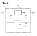
- FIG. 3 shows an exemplary structure as a block diagram the program-controlled bus components BL1 and BL2, the are realized by a conventional microprocessor unit.
- a CPU 20 communicates via an internal processor bus system 25 with a data memory 21 and a program memory 22 as well as with an I / O unit 23, which is the interface to the LIN bus system 1.
- the actuators A1, A2, A3, ... On and the sensors S1, S2 can be the same or have a similar structure.
- blower controllers e.g. a front blower regulator BL1
- another blower controller e.g. a rear blower regulator applicable if they are built identically, the same fan motors control and get the same parameters.
- the Front blower controller its blower motor e.g. for a different Can control speed.
- the protective functions e.g. Motor current limitation, power limitation, temperature limitation in air conditioning fans of a motor vehicle interior air conditioning dynamic to changing environmental conditions and operating conditions of the motor vehicle adapted become.
- the vehicle climate control unit M the necessary to adapt the protective functions Information evaluated and then by the invention Parameterization procedure via the LIN bus 1 Parameter data for dynamic adaptation of the protective functions in the blower controller BL1 or BL2, i.e. that the protective functions therein in a predetermined manner the environmental conditions and / or operating conditions of the motor vehicle to be adjusted.
- the application example below describes an example for product property selection through permanent Transmission of the selection parameters by the LIN bus master, i.e. the vehicle climate control unit M, and the selection of Performance limitation characteristic for differently powerful Air conditioning fan motors and a back pressure dependent (dynamic) power limitation of the same.
- the dynamic pressure is dependent on the boundary conditions, such as. Vehicle speed, air distribution through the air conditioning, window position, etc. on.
- the Power consumption of the blower motor is strongly dependent on the dynamic pressure, because a blower motor looks like a hydraulic machine behaves.
- the invention establishes the protective functions of the blower regulator depending on dynamic pressure.
- the vehicle climate control unit provides the blower controller with information about the dynamic pressure or in case of window adjustment or change other openings in the vehicle, e.g. the vehicle roof, the back pressure to be expected.
- a 360 W air conditioning fan is installed in vehicle x.
- the vehicle climate control unit in vehicle x transmits the value 0000 in data bits D24 to D27.
- the fan controller's product properties are adapted to the conditions in vehicle x.
- a 280 W air conditioning fan is installed in vehicle y from the same manufacturer.
- the air conditioning control unit in vehicle y transmits the value 1111 in data bits D24 to D27.
- the product property of the blower regulator is adapted to the conditions in vehicle y.
- the upper line indicates the course of the setpoints and the lower line the measured or simulated course of the power values.
- the values of the power limitation characteristics shown in FIGS. 4A and 4B were based on the same blower motor. It can be clearly seen that the current consumption of the blower motor is increased at maximum dynamic pressure.
- a Vehicle interior air conditioner also several blower motors and several blower controllers BL1 and BL2, in particular included for a front blower and a rear blower.
- the address is selected, i.e. the selection between the two blower controllers BL1 and BL2 by detecting the Level at address input Addr of the supply line 2.
- the Address assignment as a front blower controller BL1 takes place, for example if during a particular bus command to be determined a high level is detected at the address input.
- the address assignment is determined on the basis of the level at the address input Addr of the blower controllers BL1, BL2 during the assembly of the system and is adopted by the bus command in the EEPROM of the blower controller.
- the identical blower controllers BL1, BL2 now react to 2 different addresses.
- blower controllers are different via the bus system Transfer product properties.
- a 360 W front air conditioning fan is installed in vehicle x.
- the climate control unit in vehicle x transmits the value 0000 in data bits D24 to D27 of the message for the front air conditioning blower controller.
- the blower controller product property is adapted to the conditions in vehicle x.
- a 185 W rear air conditioning fan is also installed in vehicle x.
- the climate control unit in vehicle x transmits the value 1111 in data bits D24 to D27 of the message for the rear air conditioning blower regulator.
- the product characteristic of the blower regulator is adapted to the conditions of the rear system in vehicle x.
- This example is a parameterization of static and dynamic product properties.
- the parameterization of the dynamic product properties is done by transferring one or more times Parameters for dynamic and static protection functions.
- D37 8 data bits: Function: Blown air temperature act. in ° C Range of values 0 ... 190 ⁇ -40 ° C to 150 ° C 4.
- Data byte D40 D41 D42 D43 D44 D45 D46 D47 25 26 27 28 29 30 31 32 LSB MSB D40 ... D43: 4 data bits: TBD function D44 ... D47: 4 data bits: Function: Value of footwell flap OPEN 0% ... 100% resolution 6.25%
- Checksummenbyte C0 C1 C2 C3 C4 C5 C6 C7 33 34 35 36 37 38 39 40 LSB MSB C0 ... C7: 8 data bits: ADD checksum with carry inverted via data bytes 1 to 4
- a maximum temperature of 90 ° C is permissible for the fan controller. If the blown air temperature is above 50 ° C, the permissible maximum temperature in the range of 50 ° C to 60 ° C is increased linearly by 20K. The increase is also assessed by the position of the air recirculation flap and footwell flap. The maximum value of 20K is only achieved with 100% air circulation and 100% footwell OPEN. The evaluation of the air recirculation flap and the footwell flap leads to a linear decrease of 5K in the range between 100% and 70%.
- the protective function is improved by switching off the temperature.
- the fan speed is regulated to a lower maximum permissible temperature.
- the current consumption of the air conditioning fan is among others depending on the tolerance position of the blower motor, the version the air conditioning and the vehicle variant.
- the individual motor characteristic of the blower motor is measured. The evaluation depends on the environmental conditions (e.g. dynamic pressure, temperature).
- the Protective functions are attached to the motor that is actually installed customized.
- the required information is sent via data transfer (e.g. bus system, CAN) transmitted by a control device.
- data transfer e.g. bus system, CAN
- This information may only be indirect available.
- the method according to the invention is preferred here for parameterization of bus components of a vehicle interior air conditioning system using a LIN bus system and uses its standardized data structure. Instead can also bus components of other control structures with the parameterization method according to the invention using a master / slave bus structure can be parameterized.
Landscapes
- Engineering & Computer Science (AREA)
- Physics & Mathematics (AREA)
- Thermal Sciences (AREA)
- Mechanical Engineering (AREA)
- Mathematical Physics (AREA)
- Theoretical Computer Science (AREA)
- Software Systems (AREA)
- Fuzzy Systems (AREA)
- Computer Networks & Wireless Communication (AREA)
- Signal Processing (AREA)
- Air-Conditioning For Vehicles (AREA)
- Small-Scale Networks (AREA)
- Information Transfer Systems (AREA)
Abstract
Description
- Wert der Maximalstrombegrenzung,
- Wert des Temperaturschutzes,
- Wert und Steigung der Leistungsbegrenzung für den Reglerschutz und den Motorschutz,
- Regelkonstanten für Spannungsregler,
- Regelkonstanten für Stromregler,
- Regelkonstanten für Temperaturregler,
- Verstärkungsfaktoren,
- Abgleichwerte.
- Wert des Temperaturschutzes,
- Regelkreiskonstanten,
- Verstärkungsfaktoren,
- Abgleichwerte.
- Figur 1 zeigt schematisch ein Blockschaltbild einer Konfiguration eines erfindungsgemäßen Beispiels eines Kraftfahrzeuginnenraumklimatisierungssystems, bei dem eine als Master fungierende Fahrzeugklimaregeleinheit durch einen LIN-Bus mit als Slave-Einheiten fungierenden Buskomponenten, wie z.B. Gebläsereglern, Sensoren und Aktuatoren verbunden ist;
- Figur 2 zeigt schematisch ein Blockdiagramm der Struktur der Master-Einheit (Fahrzeugklimaregeleinheit);
- Figur 3 zeigt ein Blockschaltbild der Struktur eines Gebläsereglers, und
- die Figuren 4A und 4B zeigen graphisch jeweils Resultate einer erfindungsgemäß ausgeführten dynamischen Leistungsbegrenzung eines Klimagebläsemotors jeweils ohne Staudruck und bei maximalem Staudruck.
- Wert der Maximalstrombegrenzung,
- Wert des Temperaturschutzes,
- Wert und Steigung der Leistungsbegrenzung für den Reglerschutz und den Motorschutz,
- Regelkonstanten für Spannungsregler,
- Regelkonstanten für Stromregler,
- Regelkonstanten für Temperaturregler,
- Verstärkungsfaktoren,
- Abgleichwerte.
- Wert des Temperaturschutzes,
- Regelkreiskonstanten,
- Verstärkungsfaktoren,
- Abgleichwerte.
| Datenfeld 1 | |||||||
| D10 | D11 | D12 | D13 | D14 | D15 | D16 | D17 |
| 1 | 2 | 3 | 4 | 5 | 6 | 7 | 8 |
| LSB | MSB |
Funktion: Vorgabe Sollwert Motorspannung
0 ... 39: 0,0 V
40 ... 250: 2,5 V bis 13,0 V
Auflösung: 50 mV/Inc
251 ... 255: 13.0 V
| Datenfeld 2 | |||||||
| D20 | D21 | D22 | D23 | D24 | D25 | D26 | D27 |
| 9 | 10 | 11 | 12 | 13 | 14 | 15 | 16 |
| LSB | MSB |
Vorgabe Rampenzeitkonstante ÄUmotor/s bei UBATT 13,5 V
| 0000 | 0,6 V/s | 0001 | 1,2 V/s | 0010 | 1,8 V/s |
| 0011 | 2,3 V/s | 0100 | 2,9 V/s | 0101 | 3,5 V/s |
| 0110 | 4,1 V/s | 0111 | 4,7 V/s | 1000 | 5,2 V/s |
| 1001 | 5,8 V/s | 1010 bis 1111 | 5,8 V/s |
0 ... 15: Anlaufstrom 1 A ... 15 A Auflösung 1A
| Datenfeld 3 | |||||||
| D30 | D31 | D32 | D33 | D34 | D35 | D36 | D37 |
| 17 | 18 | 19 | 20 | 21 | 22 | 23 | 24 |
| X | X | X | X | X | X | X | X |
| LSB | MSB |
0 ... 190: Temperaturwert -40°C bis 150°C
| Datenfeld 4 | |||||||
| D40 | D41 | D42 | D43 | D44 | D45 | D46 | D47 |
| 25 | 26 | 27 | 28 | 29 | 30 | 31 | 32 |
| X | X | X | X | X | X | X | X |
| LSB | MSB |
1 ... 254: Wert Maximalstrom = Datenfeld4*0,2
= 0,2 A ... 50,8 A
| Datenfeld 5 | |||||||
| D50 | D51 | D52 | D53 | D54 | D55 | D56 | D57 |
| 33 | 34 | 35 | 36 | 37 | 38 | 39 | 40 |
| X | X | X | X | X | X | X | X |
| LSB | MSB |
- D30 ... D37:
- 8 Datenbits: Regelzeitkonstante Temperatur-regler
in s
1 ... 254: Regelzeitkonstante 1 s...254 s
| Datenfeld 6 | |||||||
| D60 | D61 | D62 | D63 | D64 | D65 | D66 | D67 |
| 41 | 42 | 43 | 44 | 45 | 46 | 47 | 48 |
| X | X | X | X | X | X | X | X |
| LSB | MSB |
- D40 ... D47:
- 8 Datenbits: Regelzeitkonstante Stromregler 1 ... 254: Regelzeitkonstante 4 ms...1016 ms
| Datenfeld 7 | |||||||
| D70 | D71 | D72 | D73 | D74 | D75 | D76 | D77 |
| 49 | 50 | 51 | 52 | 53 | 54 | 55 | 56 |
| X | X | X | X | X | X | X | X |
| LSB | MSB |
- D70 ... D77:
- 8 Datenbits: Regelzeitkonstante Spannungsregler
1 ...254: Regelzeitkonstante 32 ms...8128 ms
| Datenfeld 8 | |||||||
| D80 | D81 | D82 | D83 | D84 | D85 | D86 | D87 |
| 57 | 58 | 59 | 60 | 61 | 62 | 63 | 64 |
| X | X | X | X | X | X | X | X |
| LSB | MSB |
- D80 ... D87: 8 Datenbits: Übertragung Paritätsbits für erhöhte Datensicherheit wegen Parametrierdaten
- D80: Parität ODD von Datenfeld 1
- D81: Parität ODD von Datenfeld 2
- D82: Parität ODD von Datenfeld 3
- D83: Parität ODD von Datenfeld 4
- D84: Parität ODD von Datenfeld 5
- D85: Parität ODD von Datenfeld 6
- D86: Parität ODD von Datenfeld 7
- D87: tbd
- LSB: Niedrigstwertige Bitstelle
- MSB: Höchstwertige Bitstelle
- es gibt keine externe Einsatzdiagnose;
- alle Buskomponenten sind dem Master bekannt;
- das Verhalten der bekannten Buskomponente kann durch das Busprotokoll für den Einsatz in anderen Fahrzeugen angepasst werden;
- es ist eine zyklische Anpassung möglich und
- die Buskomponente braucht keinen internen veränderbaren Speicher für Initialisierungsmodus.
| 1. Datenbyte | |||||||
| D10 | D11 | D12 | D13 | D14 | D15 | D16 | D17 |
| 1 | 2 | 3 | 4 | 5 | 6 | 7 | 8 |
| LSB | MSB |
Funktion: Vorgabe Sollwert Motorspannung
| 2. Datenbyte | |||||||
| D20 | D21 | D22 | D23 | D24 | D25 | D26 | D27 |
| 9 | 10 | 11 | 12 | 13 | 14 | 15 | 16 |
| LSB | MSB |
Funktion:
Vorgabe Rampenzeitkonstante ΔUmotor / s
D24 ... D27: 4 Datenbits:
Funktion:
Klimagebläse ist nachstehend zu finden.
Die Fahrzeugklimaregeleinheit im Fahrzeug x überträgt in den Datenbits D24 bis D27 den Wert 0000. Die Produkteigenschaft des Gebläsereglers wird an die Bedingungen im Fahrzeug x angepasst.
Das Klimabediengerät im Fahrzeug y überträgt in den Datenbits D24 bis D27 den Wert 1111. Die Produkteigenschaft des Gebläsereglers wird an die Bedingungen im Fahrzeug y angepasst.
| 3. Datenbyte | |||||||
| D30 | D31 | D32 | D33 | D34 | D35 | D36 | D37 |
| 17 | 18 | 19 | 20 | 21 | 22 | 23 | 24 |
| LSB | MSB |
Funktion:
Fenster- und Schiebedachstellung 0: ZU, 1: AUF (Dynamische Anpassung)
D35 ... D37: 3 Datenbits
Klappenstellung Staudruckregelung 8 Zustände
- 000: Staudruckregelung 0%
- 001: Staudruckregelung 30%
- 010: Staudruckregelung 55%
- 011: Staudruckregelung 75%
- 100: Staudruckregelung 80%
- 101: Staudruckregelung 90%
- 110: Staudruckregelung 95%
- 111: Staudruckregelung 100% (Anhebung inaktiv)
dynamischen Anpassung)
| 4. Datenbyte | |||||||
| D40 | D41 | D42 | D43 | D44 | D45 | D46 | D47 |
| 25 | 26 | 27 | 28 | 29 | 30 | 31 | 32 |
| LSB | MSB |
Funktion:
- Fahrgeschwindigkeitswert V0 ab der die Anhebung aktiviert werden soll:
- Auflösung: 20 km/h / Inc + 80km/h Offset (V0 = 80 km/h ... 140 km/h)
Funktion:
- Fahrgeschwindigkeitswert (V0 + VMAX) ab der die maximale Anhebung erreicht werden soll
- Auflösung: 20 km/h /Inc (VMAX = +20km/h ... +80 km/h)
| Checksummenbyte | |||||||
| C0 | C1 | C2 | C3 | C4 | C5 | C6 | C7 |
| 33 | 34 | 35 | 36 | 37 | 38 | 39 | 40 |
| LSB | MSB |
Die identischen Gebläseregler BL1, BL2 reagieren jetzt auf 2 verschiedene Adressen.
| 1. Datenbyte | |||||||
| D10 | D11 | D12 | D13 | D14 | D15 | D16 | D17 |
| 1 | 2 | 3 | 4 | 5 | 6 | 7 | 8 |
| LSB | MSB |
Funktion: Vorgabe Sollwert Motorspannung
| 2. Datenbyte | |||||||
| D20 | D21 | D22 | D23 | D24 | D25 | D26 | D27 |
| 9 | 10 | 11 | 12 | 13 | 14 | 15 | 16 |
| LSB | MSB |
Funktion:
- Vorgabe Rampenzeitkonstante ΔUmotor / s
Funktion:
- Vorgabe der Leistungsbegrenzungskennline (Parametrisierung)
- 0000: Leistungsbegrenzungskennlinie 1 (360 W Motor)
- 0101: Leistungsbegrenzungskennlinie 2 (320 W Motor)
- 1111: Leistungsbegrenzungskennlinie 3 (280 W Motor)
Die Klimaregeleinheit im Fahrzeug x überträgt in den Datenbits D24 bis D27 der Nachricht für den Frontklimagebläseregler den Wert 0000. Die Produkteigenschaft des Gebläsereglers wird an die Bedingungen im Fahrzeug x angepasst.
Die Klimaregeleinheit im Fahrzeug x überträgt in den Datenbits D24 bis D27 der Nachricht für den Heckklimagebläseregler den Wert 1111. Die Produkteigenschaft des Gebläsereglers wird an die Bedingungen der Heckanlage im Fahrzeug x angepasst.
Die im Gebläseregler vorhandenen identischen Berechnungsroutinen werden durch die Adressvergabe statisch an den Einsatzort des Klimagebläses (Front-Heck) angepasst.
| 3. Datenbyte | |||||||
| D30 | D31 | D32 | D33 | D34 | D35 | D36 | D37 |
| 17 | 18 | 19 | 20 | 21 | 22 | 23 | 24 |
| LSB | MSB |
Funktion: TBD
| 4. Datenbyte | |||||||
| D40 | D41 | D42 | D43 | D44 | D45 | D46 | D47 |
| 25 | 26 | 27 | 28 | 29 | 30 | 31 | 32 |
| LSB | MSB |
Funktion: TBD
| Checksummenbyte | |||||||
| C0 | C1 | C2 | C3 | C4 | C5 | C6 | C7 |
| 33 | 34 | 35 | 36 | 37 | 38 | 39 | 40 |
| LSB | MSB |
| 1. Datenbyte | |||||||
| D10 | D11 | D12 | D13 | D14 | D15 | D16 | D17 |
| 1 | 2 | 3 | 4 | 5 | 6 | 7 | 8 |
| LSB | MSB |
Funktion: Kennung Initialisierungsnachricht
| 2. Datenbyte | |||||||
| D20 | D21 | D22 | D23 | D24 | D25 | D26 | D27 |
| 9 | 10 | 11 | 12 | 13 | 14 | 15 | 16 |
| LSB | MSB |
Funktion:
Funktion:
- Vorgabe der Leistungsbegrenzungskennline (Parametrisierung) Vorgabewert:
- 0000: Leistungsbegrenzungskennlinie 1 (360 W Motor)
- 0101: Leistungsbegrenzungskennlinie 2 (320 W Motor)
- 1111: Leistungsbegrenzungskennlinie 3 (280 W Motor)
| 3. Datenbyte | |||||||
| D30 | D31 | D32 | D33 | D34 | D35 | D36 | D37 |
| 17 | 18 | 19 | 20 | 21 | 22 | 23 | 24 |
| LSB | MSB |
Funktion:
Temperatur Verschiebung der Zulässigen Maxtemperatur + 0 ... 30 K
Auflösung 2 K
D34 ... D37: 4 Datenbits:
Funktion:
TBLMAX = TBL0 + Wert (D34...D37) in 0 ... 30 K
| 4. Datenbyte | |||||||
| D40 | D41 | D42 | D43 | D44 | D45 | D46 | D47 |
| 25 | 26 | 27 | 28 | 29 | 30 | 31 | 32 |
| LSB | MSB |
Funktion:
- Wertebereich 0 ... 127
- Zulässige Maximaltemperatur in °C
- D47: TBD
| Checksummenbyte | |||||||
| C0 | C1 | C2 | C3 | C4 | C5 | C6 | C7 |
| 33 | 34 | 35 | 36 | 37 | 38 | 39 | 40 |
| LSB | MSB |
| 1. Datenbyte | |||||||
| D10 | D11 | D12 | D13 | D14 | D15 | D16 | D17 |
| 1 | 2 | 3 | 4 | 5 | 6 | 7 | 8 |
| LSB | MSB |
Funktion: Vorgabe Sollwert Motorspannung
| 2. Datenbyte | |||||||
| D20 | D21 | D22 | D23 | D24 | D25 | D26 | D27 |
| 9 | 10 | 11 | 12 | 13 | 14 | 15 | 16 |
| LSB | MSB |
Funktion:
Vorgabe Rampenzeitkonstante ΔUmotor / s
D24 ... D26: 4 Datenbits:
Funktion:
Wert Umluftklappe 0 % ... 100% Auflösung 6,25%
| 3. Datenbyte | |||||||
| D30 | D31 | D32 | D33 | D34 | D35 | D36 | D37 |
| 17 | 18 | 19 | 20 | 21 | 22 | 23 | 24 |
| LSB | MSB |
Funktion: Blaslufttemperatur akt. in °C
Wertebereich 0 ... 190 → -40°C bis 150°C
| 4. Datenbyte | |||||||
| D40 | D41 | D42 | D43 | D44 | D45 | D46 | D47 |
| 25 | 26 | 27 | 28 | 29 | 30 | 31 | 32 |
| LSB | MSB |
Funktion TBD
D44 ... D47: 4 Datenbits:
Funktion:
Wert Fußraumklappe AUF 0 % ... 100% Auflösung 6,25%
| Checksummenbyte | |||||||
| C0 | C1 | C2 | C3 | C4 | C5 | C6 | C7 |
| 33 | 34 | 35 | 36 | 37 | 38 | 39 | 40 |
| LSB | MSB |
Liegt die Blaslufttemperatur über 50°C wird die zulässige Maximaltemperatur im Bereich 50°C bis 60°C linear um 20K angehoben.
Die Anhebung wird gleichzeitig noch durch die Stellung der Umluftklappe und Fußraumklappe bewertet.
Der Maximalwert 20K wird nur bei 100% Umluft und 100% Fußraum AUF erreicht.
Die Bewertung der Umluftklappe und der Fußraumklappe führt im Bereich zwischen 100% bis 70% zu einer linearen Absenkung um je 5K.
Bei niederen Umgebungstemperaturen (Blasluft) oder bei Klappenstellungen die zu einer besseren Entwärmung des Produkts führen wird auf eine niedrigere maximal zulässige Gebläsereglertemperatur geregelt.
Es ist zu bemerken, dass die obige Beschreibung beispielhaft programmgesteuerte Buskomponenten unter Verwendung üblicher Mikroprozessorstrukturen beschreibt. Dies dient jedoch lediglich zur Veranschaulichung, und die Buskomponenten können auch unter Verwendung von zustandsgesteuerten Vorrichtungen realisiert werden.
Claims (39)
- Verfahren zur Parametrisierung von Buskomponenten (A1, ... An, BL1, BL2, S1, S2), die als programmgesteuertes Slave-Einheiten durch ein Bussystem (1) mit Master-Slave-Struktur mit einer programmgesteuerten Master-Einheit (M) kommunizieren können,
dadurch gekennzeichnet, dass den Buskomponenten (A1, ... An, BL1, BL2, S1, S2) individuelle Parameter von der Master-Einheit (M) durch einen Parametrisierungsschritt einprogrammiert werden und dass dieser Parametrisierungsschritt innerhalb des Datenprotokolls des Bussystems (1) von der Master-Einheit (M) für jede Buskomponente einmalig oder mehrfach und/oder zyklisch durchgeführt wird. - Verfahren nach Anspruch 1, dadurch gekennzeichnet, dass der Parametrisierungsschritt von der Master-Einheit (M) ereignisgetriggert durchgeführt wird.
- Verfahren nach Anspruch 1 oder 2, dadurch gekennzeichnet, dass die von der Master-Einheit (M) im Parametrisierungsschritt zur jeweiligen Buskomponente (A1, ... An, BL1, BL2, S1, S2) übertragenen Parameter in der jeweiligen Buskomponente nicht dauerhaft gespeichert und bei jedem Parametrisierungsschritt aktualisiert bzw. überschrieben werden.
- Verfahren nach einem der Ansprüche 1 bis 3, dadurch gekennzeichnet, dass durch den Parametrisierungsschritt statische Parameter von der Master-Einheit (M) an eine jeweilige Buskomponente übertragen werden.
- Verfahren nach einem der Ansprüche 1 bis 3, dadurch gekennzeichnet, dass durch den Parametrisierungsschritt dynamisch veränderliche Parameter von der Master-Einheit (M) an eine jeweilige Buskomponenten übertragen werden.
- Verfahren nach einem der vorangehenden Ansprüche,
dadurch gekennzeichnet, dass es für die Parametrisierung von Buskomponenten (A1, ... An, BL1, BL2, S1, S2) der Kraftfahrzeuginnenraumklimatisierung verwendet wird, wobei die Master-Einheit (M) eine Fahrzeugklimaregeleinheit ist. ' - Verfahren nach Anspruch 6, dadurch gekennzeichnet, dass als Bussystem (1) ein LIN-Bussystem eingesetzt ist.
- Verfahren nach Anspruch 6 oder 7, dadurch gekennzeichnet, dass Parameter, die fahrzeugspezifische Eigenschaften betreffen, durch den Parametrisierungsschritt von der Fahrzeugklimaregeleinheit (M) an die Buskomponenten (A1, ... An, BL1, BL2, S1, S2) zum Zeitpunkt und am Ort des Einbaus der Buskomponenten in das Kraftfahrzeug übertragen werden.
- Verfahren nach Anspruch 6 oder 7, dadurch gekennzeichnet, dass der Parametrisierungsschritt wenigstens bei jedem Neustart des Kraftfahrzeugs durchgeführt wird.
- Verfahren nach einem der Ansprüche 6 bis 9, dadurch gekennzeichnet, dass im Parametrisierungsschritt von der Fahrzeugklimaregeleinheit (M) statische Parameter an einen als Buskomponente eingesetzten Gebläseregler übertragen werden, die insbesondere sind:Wert der Maximalstrombegrenzung,Wert des Temperaturschutzes,Wert und Steigung der Leistungsbegrenzung für den Reglerschutz und den Motorschutz,Regelkonstanten für Spannungsregler,Regelkonstanten für Stromregler,Regelkonstanten für Temperaturregler,Verstärkungsfaktoren,Abgleichwerte.
- Verfahren nach einem der Ansprüche 6 bis 9, das im Parametrisierungsschritt von der Fahrzeugklimaregeleinheit (M) an ein als Buskomponente eingesetztes Zuheizsystem insbesondere folgende Parameter übertragen werden:Wert des Temperaturschutzes,Regelkreiskonstanten,Verstärkungsfaktoren,Abgleichwerte.
- Verfahren nach einem der Ansprüche 6 bis 9, dadurch gekennzeichnet, dass von der Fahrzeugklimaregeleinheit (M) im Parametrisierungsschritt dynamische Schutzfunktionen eines Klimagebläses betreffende Parameter an einen als Buskomponente eingesetzten Gebläseregler (BL1, BL2) übertragen werden, wobei diese Schutzfunktionen insbesondere sind:eine Gebläsemotorstrombegrenzung und/odereine Gebläsemotorleistungsbegrenzung und/odereine Gebläsemotortemperaturbegrenzung.
- Verfahren nach Anspruch 12, dadurch gekennzeichnet, dass die Fahrzeugklimaregeleinheit (M) dem Gebläseregler (BL1, BL2) einen dem momentanen und/oder zu erwartenden Staudruck entsprechenden Parameter überträgt.
- Verfahren nach Anspruch 12, oder 13, dadurch gekennzeichnet, dass von der Fahrzeugklimaregeleinheit (M) im Parametrisierungsschritt ein einer Veränderung der Bordnetzspannung (VBATT) des Fahrzeugs entsprechender Parameter dem Gebläseregler (BL1, BL2) übertragen wird.
- Verfahren nach Anspruch 13 oder 14, dadurch gekennzeichnet, dass der dem zu erwartenden Staudruck entsprechende Parameter und der einer erwarteten Veränderung der Bordnetzspannung (VBATT) entsprechender Parameter von der Fahrzeugklimaregeleinheit vor dem Zeitpunkt der tatsächlichen Änderung dieser Größen an den Gebläseregler (BL1, BL2) übertragen werden.
- Verfahren nach Anspruch 15, dadurch gekennzeichnet, dass der Gebläseregler (BL1, BL2) auf Grund der von der Fahrzeugklimaregeleinheit (M) übertragenen Parameter eine Vorsteuerung ausführt.
- Verfahren nach Anspruch 15 oder 16, dadurch gekennzeichnet, dass der Gebläseregler (BL1, BL2) auf Grund der von der Fahrzeugklimaregeleinheit (M) übertragenen Parameter seinen momentanen Regelalgorithmus ändert.
- Verfahren nach Anspruch 12, dadurch gekennzeichnet, dass von der Fahrzeugklimaregeleinheit ein der Umgebungstemperatur entsprechender Parameter an der Gebläseregler (BL1, BL2) übertragen wird.
- Verfahren nach Anspruch 18, dadurch gekennzeichnet, dass als die Umgebungstemperatur eine der Temperatur der vom Klimagebläse angesaugten Luft entsprechende Information übertragen wird.
- Verfahren nach einem der Ansprüche 13 bis 19, dadurch gekennzeichnet, dass die Informationen über den Staudruck und/oder die Temperatur der vom Gebläse angesaugten Luft gemessen werden.
- Verfahren nach einem der Ansprüche 13 bis 19, dadurch gekennzeichnet, dass die Informationen über den Staudruck und/oder die Temperatur der vom Gebläse angesaugten Luft von der Fahrzeugklimaregeleinheit (M) aus bekannten Fahrzeugbetriebsbedingungen ermittelt werden.
- System zur Parametrisierung von Komponenten eines Kraftfahrzeuginnenraumklimatisierungssystems, die als programmgesteuerte Slave-Einheiten (A1, ... An, BL1, BL1, S1, S2) durch ein Bussystem (1) auf Grund eines entsprechenden Busdatenprotokolls mit einer als Master-Einheit (M) fungierenden programmgesteuerten Fahrzeugklimaregeleinheit kommunizieren,
dadurch gekennzeichnet, dass das System zur Parametrisierung der Buskomponenten durch eine das Busdatenprotokoll nutzende einmalige oder mehrfache und/oder zyklische Datenübertragung von der Master-Einheit (M) zur jeweiligen Slave-Einheit (A1, ... An, BL1, BL1, S1, S2) eingerichtet ist. - System nach Anspruch 22, dadurch gekennzeichnet, dass die Buskomponenten (A1, ... An, BL1, BL1, S1, S2) jeweils eine Zentralprozessoreinheit (20) und einen Datenspeicher (21) aufweisen, um die von der Master-Einheit (M) empfangenden Parameter nicht dauerhaft zu speichern.
- System nach Anspruch 22, dadurch gekennzeichnet, dass das Bussystem (1) ein LIN-Bus und das Busdatenprotokoll ein LIN-Busdatenprotokoll ist.
- System nach Anspruch 23, dadurch gekennzeichnet, dass die Zentralprozessoreinheit (20) der Buskomponenten (A1, ... An, BL1, BL1, S1, S2) dazu programmiert ist, die im Datenspeicher (21) gespeicherten Parameter auf jede Parameterübertragung durch die Master-Einheit (M) zu aktualisieren bzw. zu überschreiben.
- System nach einem der Ansprüche 22 bis 25, dadurch gekennzeichnet, dass die Fahrzeugklimaregeleinheit (M) dazu programmiert ist, die Parameter zum Zeitpunkt und am Ort des Einbaus der jeweiligen Buskomponente in das Kraftfahrzeug zu übertragen.
- System nach einem der Ansprüche 22 bis 25, dadurch gekennzeichnet, dass die Fahrzeugklimaregeleinheit (M) dazu programmiert ist, die Parameter wenigstens bei jedem Neustart des Kraftfahrzeugs zu übertragen.
- System nach einem der Ansprüche 22 bis 27, dadurch gekennzeichnet, dass die Fahrzeugklimaregeleinheit (M) dazu programmiert ist, insbesondere die folgenden Parameter an einen Klimagebläseregler zu übertragen: - Wert der Maximalstrombegrenzung,Wert des Temperaturschutzes,Wert und Steigung der Leistungsbegrenzung für den Reglerschutz und den Motorschutz,Regelkonstanten für Spannungsregler,Regelkonstanten für Stromregler,Regelkonstanten für Temperaturregler,Verstärkungsfaktoren,Abgleichwerte.
- System nach einem der Ansprüche 22 bis 27, dadurch gekennzeichnet, dass die Fahrzeugklimaregeleinheit (M) dazu programmiert ist, insbesondere die folgende Parameter an ein zum Kraftfahrzeuginnenraumklimatisierungssystem gehörendes Zuheizsystem zu übertragen:Wert des Temperaturschutzes,Regelkreiskonstanten,Verstärkungsfaktoren,Abgleichwerte.
- System nach einem der Ansprüche 22 bis 27, dadurch gekennzeichnet, dass die Fahrzeugklimaregeleinheit (M) dazu programmiert ist, dynamische Schutzfunktionen eines Klimagebläses betreffende Parameter an ein Klimagebläseregler (BL1, BL2) des Kraftfahrzeuginnenraumklimatisierungssystems zu übertragen, wobei diese Schutzfunktionen insbesondere sind:eine Gebläsemotorstrombegrenzung und/odereine Gebläsemotorleistungsbegrenzung und/odereine Gebläsemotortemperaturbegrenzung.
- System nach Anspruch 30, dadurch gekennzeichnet, dass die Fahrzeugklimaregeleinheit (M) dazu programmiert ist, dem Klimagebläseregler (BL1, BL2) einen dem momentanen oder einem zu erwartenden Staudruck entsprechenden Parameter zu übertragen.
- System nach Anspruch 30 oder 31, dadurch gekennzeichnet, dass die Fahrzeugklimaregeleinheit (M) dazu programmiert ist, dem Gebläseregler (BL1, BL2) einen einer Veränderung der Bordnetzspannung des Kraftfahrzeugs entsprechenden Parameter zu übertragen.
- System nach Anspruch 31 oder 32, dadurch gekennzeichnet, dass die Fahrzeugklimaregeleinheit (M) dazu programmiert ist, den dem zu erwartenden Staudruck entsprechenden Parameter und den einer anstehenden Veränderung der Bordnetzspannung (VBATT) entsprechenden Parameter vor dem Zeitpunkt der tatsächlichen Änderung dieser Größen an den Gebläseregler (BL1, BL2) zu übertragen.
- System nach Anspruch 33, dadurch gekennzeichnet, dass der Gebläseregler (BL1, BL2) dazu programmiert ist, auf Grund der empfangenen Parameter eine Vorsteuerung auszuführen.
- System nach Anspruch 33 oder 34, dadurch gekennzeichnet, dass der Gebläseregler (BL1, BL2) dazu programmiert ist, auf Grund der empfangenen Parameter einen momentanen Regelalgorithmus zu ändern.
- System nach Anspruch 30, dadurch gekennzeichnet, dass die Fahrzeugklimaregeleinheit (M) dazu programmiert ist, einen der Umgebungstemperatur entsprechenden Parameter an den Gebläseregler (BL1, BL2) zu übertragen.
- System nach Anspruch 36, dadurch gekennzeichnet, dass die Fahrzeugklimaregeleinheit (M) dazu programmiert ist, als die Umgebungstemperatur einen die Lufttemperatur der vom Klimagebläse angesaugten Luft entsprechenden Parameter zu übertragen.
- System nach einem der Ansprüche 31 bis 37, dadurch gekennzeichnet, dass die Informationen, die die Fahrzeugklimaregeleinheit (M) hinsichtlich des Staudrucks und/oder der Temperatur an den Gebläseregler (BL1, BL2) übertragt, sensorisch gemessene Größen sind.
- System nach einem der Ansprüche 31 bis 37, dadurch gekennzeichnet, dass die Fahrzeugklimaregeleinheit (M) dazu programmiert ist, die an den Gebläseregler (BL1, BL2) übertragenen Informationen bezüglich Staudruck und/oder Temperatur aus bekannten Fahrzeugbetriebsbedingungen zu ermitteln.
Applications Claiming Priority (2)
| Application Number | Priority Date | Filing Date | Title |
|---|---|---|---|
| DE10261736A DE10261736A1 (de) | 2002-12-30 | 2002-12-30 | Verfahren und System zur Parametrisierung von Buskomponenten |
| DE10261736 | 2002-12-30 |
Publications (3)
| Publication Number | Publication Date |
|---|---|
| EP1439670A2 true EP1439670A2 (de) | 2004-07-21 |
| EP1439670A3 EP1439670A3 (de) | 2006-01-25 |
| EP1439670B1 EP1439670B1 (de) | 2013-01-09 |
Family
ID=32478119
Family Applications (1)
| Application Number | Title | Priority Date | Filing Date |
|---|---|---|---|
| EP03025582A Expired - Lifetime EP1439670B1 (de) | 2002-12-30 | 2003-11-08 | Verfahren und System zur Parametisierung von Buskomponenten |
Country Status (2)
| Country | Link |
|---|---|
| EP (1) | EP1439670B1 (de) |
| DE (1) | DE10261736A1 (de) |
Cited By (3)
| Publication number | Priority date | Publication date | Assignee | Title |
|---|---|---|---|---|
| CN100397839C (zh) * | 2004-11-26 | 2008-06-25 | 浙江中科正方电子技术有限公司 | 汽车车身can总线控制系统 |
| WO2013079315A1 (de) * | 2011-12-01 | 2013-06-06 | Robert Bosch Gmbh | Sensorübertragungsvorrichtung und verfahren zur übertragung von nutzdaten von einer mehrzahl von sensoren an eine bussteuervorrichtung für ein fahrzeug |
| CN104070961A (zh) * | 2014-07-04 | 2014-10-01 | 上汽通用五菱汽车股份有限公司 | 一种汽车空调配置自动识别的方法 |
Families Citing this family (5)
| Publication number | Priority date | Publication date | Assignee | Title |
|---|---|---|---|---|
| WO2006059285A1 (en) * | 2004-12-01 | 2006-06-08 | Philips Intellectual Property & Standards Gmbh | Interface and method for transmitting bits to a two-wire bus applying a lin protocol |
| DE102005011578A1 (de) * | 2005-03-14 | 2006-09-21 | Robert Bosch Gmbh | Verfahren und Schaltungsanordnung zur Begrenzung der Stromaufnahme eines Gleichstrommotors |
| DE102012004925B4 (de) * | 2012-03-10 | 2015-10-29 | Volkswagen Aktiengesellschaft | Verfahren zur Inbetriebnahme einer Funktion einer Komponente eines Fahrzeugs sowie entsprechende Komponente, Verbund von Komponenten und Fahrzeug |
| CN106576063B (zh) * | 2014-08-08 | 2020-08-04 | 捷温有限责任公司 | 总线系统和总线系统控制方法 |
| DE102014116723A1 (de) * | 2014-11-14 | 2016-05-19 | TWT GmbH | Steuerungssystem für zumindest ein Transportmittel |
Citations (4)
| Publication number | Priority date | Publication date | Assignee | Title |
|---|---|---|---|---|
| US6098098A (en) | 1997-11-14 | 2000-08-01 | Enhanced Messaging Systems, Inc. | System for managing the configuration of multiple computer devices |
| WO2001015920A1 (de) | 1999-09-01 | 2001-03-08 | Robert Bosch Gmbh | Kraftfahrzeug-innenraumklimatisierung |
| WO2002037923A2 (de) | 2000-11-08 | 2002-05-16 | Bayerische Motoren Werke Aktiengesellschaft | Datenbus, insbesondere in kraftfahrzeugen |
| EP1223710A2 (de) | 2000-11-20 | 2002-07-17 | Vacon Oyj | System und Verfahren zur Steuerung von Aktuatoren |
Family Cites Families (3)
| Publication number | Priority date | Publication date | Assignee | Title |
|---|---|---|---|---|
| JPH06321029A (ja) * | 1993-05-19 | 1994-11-22 | Alps Electric Co Ltd | 多重通信システム |
| DE19842593C2 (de) * | 1998-09-17 | 2001-05-03 | Abb Patent Gmbh | Verfahren zum Betrieb eines Busmasters an einem Feldbus |
| US6460356B1 (en) * | 2001-10-02 | 2002-10-08 | Paccar Inc. | HVAC control system for a multizoned vehicle |
-
2002
- 2002-12-30 DE DE10261736A patent/DE10261736A1/de not_active Withdrawn
-
2003
- 2003-11-08 EP EP03025582A patent/EP1439670B1/de not_active Expired - Lifetime
Patent Citations (4)
| Publication number | Priority date | Publication date | Assignee | Title |
|---|---|---|---|---|
| US6098098A (en) | 1997-11-14 | 2000-08-01 | Enhanced Messaging Systems, Inc. | System for managing the configuration of multiple computer devices |
| WO2001015920A1 (de) | 1999-09-01 | 2001-03-08 | Robert Bosch Gmbh | Kraftfahrzeug-innenraumklimatisierung |
| WO2002037923A2 (de) | 2000-11-08 | 2002-05-16 | Bayerische Motoren Werke Aktiengesellschaft | Datenbus, insbesondere in kraftfahrzeugen |
| EP1223710A2 (de) | 2000-11-20 | 2002-07-17 | Vacon Oyj | System und Verfahren zur Steuerung von Aktuatoren |
Cited By (4)
| Publication number | Priority date | Publication date | Assignee | Title |
|---|---|---|---|---|
| CN100397839C (zh) * | 2004-11-26 | 2008-06-25 | 浙江中科正方电子技术有限公司 | 汽车车身can总线控制系统 |
| WO2013079315A1 (de) * | 2011-12-01 | 2013-06-06 | Robert Bosch Gmbh | Sensorübertragungsvorrichtung und verfahren zur übertragung von nutzdaten von einer mehrzahl von sensoren an eine bussteuervorrichtung für ein fahrzeug |
| US9767055B2 (en) | 2011-12-01 | 2017-09-19 | Robert Bosch Gmbh | Sensor transmission device and method for transmitting payload data from multiple sensors to a bus control device for a vehicle |
| CN104070961A (zh) * | 2014-07-04 | 2014-10-01 | 上汽通用五菱汽车股份有限公司 | 一种汽车空调配置自动识别的方法 |
Also Published As
| Publication number | Publication date |
|---|---|
| DE10261736A1 (de) | 2004-07-08 |
| EP1439670A3 (de) | 2006-01-25 |
| EP1439670B1 (de) | 2013-01-09 |
Similar Documents
| Publication | Publication Date | Title |
|---|---|---|
| DE602005005108T2 (de) | Steuerungssystem für ein Netzwerk in einem Fahrzeug | |
| DE60219705T2 (de) | Ausfallsicheres Überwachunggssystem sowie passende Methode in eine integriete Fahrzeugsteuerung | |
| DE69923593T2 (de) | Konfigurations-programmierung von eingangs/ausgangs- netzwerkverbindungenseinheiten in einem multiplexierten kraftfahrzeug- kommunikationssytem | |
| DE102012102173B4 (de) | Re-konfigurierbare Schnittstellen-basierende elektrische Architektur | |
| EP1332588B1 (de) | Datenbus, insbesondere in kraftfahrzeugen | |
| DE102016113244A1 (de) | Fahrzeuginternes aufzeichnungssystem | |
| DE102017206548A1 (de) | Fahrzeug, regelverfahren desselben und leistungsregelungsvorrichtung für ein fahrzeug | |
| DE102016109599A1 (de) | Steuern der HVAC-Verdichterdrehzahl in einem Fahrzeug | |
| DE102013213922A1 (de) | Fahrzeugbremsensystem und Verfahren, um dieses zu betreiben | |
| EP2137030A2 (de) | Kommunikationssystem eines fahrzeugs und verfahren zum betreiben eines kommunikationssystems | |
| EP1439670A2 (de) | Verfahren und System zur Parametisierung von Buskomponenten | |
| DE102018128857A1 (de) | System und Verfahren zum Steuern eines Kompressors eines Kaltstart-Fahrzeugs | |
| DE102013205390A1 (de) | Datenausgabevorrichtung für ein fahrzeug | |
| DE112009000500T5 (de) | Weiterleitungseinrichtung, Kommunikationssystem und Kommunikationsverfahren | |
| DE102017111771A1 (de) | Errergerstrombegrenzter Leistungsgenerator | |
| DE102021102278A1 (de) | Nachrichtenauthentifizierung von fahrzeugen durch proof-of-work | |
| EP1929607A2 (de) | Energiemanagementsystem für ein kraftfahrzeug | |
| DE112015003669B4 (de) | Bussystem und Verfahren zu dessen Steuerung | |
| DE102016207129A1 (de) | Verfahren zum Betrieb eines elektromotorischen Kältemittelverdichters | |
| DE60025969T2 (de) | Kraftfahrzeug-Steuerungssystem and Verfahren geeignet zur Revision der Steuerldatenübertragungsfunktion | |
| DE102018106110A1 (de) | Klimasteuerung für hybridelektrofahrzeuge mit motor-stopp-start | |
| WO2007025841A1 (de) | Verfahren zur steuerung einer fahrzeug-antriebseinheit | |
| DE102009045975A1 (de) | Kraftfahrzeugsteuerungssystem | |
| DE112022001361T5 (de) | Elektrische Motorsteuerung für Hochleistungshydrauliksysteme | |
| DE102021111961A1 (de) | Wärmemanagementsystem für ein elektrifiziertes Kraftfahrzeug |
Legal Events
| Date | Code | Title | Description |
|---|---|---|---|
| PUAI | Public reference made under article 153(3) epc to a published international application that has entered the european phase |
Free format text: ORIGINAL CODE: 0009012 |
|
| AK | Designated contracting states |
Kind code of ref document: A2 Designated state(s): AT BE BG CH CY CZ DE DK EE ES FI FR GB GR HU IE IT LI LU MC NL PT RO SE SI SK TR |
|
| AX | Request for extension of the european patent |
Extension state: AL LT LV MK |
|
| PUAL | Search report despatched |
Free format text: ORIGINAL CODE: 0009013 |
|
| AK | Designated contracting states |
Kind code of ref document: A3 Designated state(s): AT BE BG CH CY CZ DE DK EE ES FI FR GB GR HU IE IT LI LU MC NL PT RO SE SI SK TR |
|
| AX | Request for extension of the european patent |
Extension state: AL LT LV MK |
|
| RIC1 | Information provided on ipc code assigned before grant |
Ipc: H04L 12/403 20060101AFI20040528BHEP Ipc: B60H 1/00 20060101ALI20051205BHEP Ipc: H04L 29/02 20060101ALI20051205BHEP |
|
| 17P | Request for examination filed |
Effective date: 20060725 |
|
| AKX | Designation fees paid |
Designated state(s): DE FR GB SE |
|
| 17Q | First examination report despatched |
Effective date: 20070606 |
|
| GRAP | Despatch of communication of intention to grant a patent |
Free format text: ORIGINAL CODE: EPIDOSNIGR1 |
|
| GRAS | Grant fee paid |
Free format text: ORIGINAL CODE: EPIDOSNIGR3 |
|
| GRAA | (expected) grant |
Free format text: ORIGINAL CODE: 0009210 |
|
| AK | Designated contracting states |
Kind code of ref document: B1 Designated state(s): DE FR GB SE |
|
| REG | Reference to a national code |
Ref country code: GB Ref legal event code: FG4D Free format text: NOT ENGLISH |
|
| REG | Reference to a national code |
Ref country code: DE Ref legal event code: R096 Ref document number: 50314659 Country of ref document: DE Effective date: 20130228 |
|
| PG25 | Lapsed in a contracting state [announced via postgrant information from national office to epo] |
Ref country code: SE Free format text: LAPSE BECAUSE OF FAILURE TO SUBMIT A TRANSLATION OF THE DESCRIPTION OR TO PAY THE FEE WITHIN THE PRESCRIBED TIME-LIMIT Effective date: 20130109 |
|
| PLBE | No opposition filed within time limit |
Free format text: ORIGINAL CODE: 0009261 |
|
| STAA | Information on the status of an ep patent application or granted ep patent |
Free format text: STATUS: NO OPPOSITION FILED WITHIN TIME LIMIT |
|
| 26N | No opposition filed |
Effective date: 20131010 |
|
| REG | Reference to a national code |
Ref country code: DE Ref legal event code: R097 Ref document number: 50314659 Country of ref document: DE Effective date: 20131010 |
|
| GBPC | Gb: european patent ceased through non-payment of renewal fee |
Effective date: 20131108 |
|
| REG | Reference to a national code |
Ref country code: FR Ref legal event code: ST Effective date: 20140731 |
|
| PG25 | Lapsed in a contracting state [announced via postgrant information from national office to epo] |
Ref country code: GB Free format text: LAPSE BECAUSE OF NON-PAYMENT OF DUE FEES Effective date: 20131108 Ref country code: FR Free format text: LAPSE BECAUSE OF NON-PAYMENT OF DUE FEES Effective date: 20131202 |
|
| REG | Reference to a national code |
Ref country code: DE Ref legal event code: R084 Ref document number: 50314659 Country of ref document: DE |
|
| REG | Reference to a national code |
Ref country code: DE Ref legal event code: R084 Ref document number: 50314659 Country of ref document: DE Effective date: 20150227 |
|
| PGFP | Annual fee paid to national office [announced via postgrant information from national office to epo] |
Ref country code: DE Payment date: 20190124 Year of fee payment: 16 |
|
| REG | Reference to a national code |
Ref country code: DE Ref legal event code: R119 Ref document number: 50314659 Country of ref document: DE |
|
| PG25 | Lapsed in a contracting state [announced via postgrant information from national office to epo] |
Ref country code: DE Free format text: LAPSE BECAUSE OF NON-PAYMENT OF DUE FEES Effective date: 20200603 |