EP1439122A1 - Faltenbalg zur mechanischen Verbindung von zwei, in einem vorgegebenen Abstand zueinander angeordneten Rohren - Google Patents
Faltenbalg zur mechanischen Verbindung von zwei, in einem vorgegebenen Abstand zueinander angeordneten Rohren Download PDFInfo
- Publication number
- EP1439122A1 EP1439122A1 EP03027919A EP03027919A EP1439122A1 EP 1439122 A1 EP1439122 A1 EP 1439122A1 EP 03027919 A EP03027919 A EP 03027919A EP 03027919 A EP03027919 A EP 03027919A EP 1439122 A1 EP1439122 A1 EP 1439122A1
- Authority
- EP
- European Patent Office
- Prior art keywords
- bellows
- discharge pipe
- joint
- adjacent
- pipe
- Prior art date
- Legal status (The legal status is an assumption and is not a legal conclusion. Google has not performed a legal analysis and makes no representation as to the accuracy of the status listed.)
- Granted
Links
- 230000007704 transition Effects 0.000 claims description 5
- 230000009969 flowable effect Effects 0.000 claims description 2
- 239000012530 fluid Substances 0.000 abstract 1
- 238000009434 installation Methods 0.000 description 1
Images

Classifications
-
- B—PERFORMING OPERATIONS; TRANSPORTING
- B64—AIRCRAFT; AVIATION; COSMONAUTICS
- B64C—AEROPLANES; HELICOPTERS
- B64C1/00—Fuselages; Constructional features common to fuselages, wings, stabilising surfaces or the like
- B64C1/14—Windows; Doors; Hatch covers or access panels; Surrounding frame structures; Canopies; Windscreens accessories therefor, e.g. pressure sensors, water deflectors, hinges, seals, handles, latches, windscreen wipers
- B64C1/1407—Doors; surrounding frames
- B64C1/1453—Drain masts
-
- B—PERFORMING OPERATIONS; TRANSPORTING
- B64—AIRCRAFT; AVIATION; COSMONAUTICS
- B64D—EQUIPMENT FOR FITTING IN OR TO AIRCRAFT; FLIGHT SUITS; PARACHUTES; ARRANGEMENT OR MOUNTING OF POWER PLANTS OR PROPULSION TRANSMISSIONS IN AIRCRAFT
- B64D11/00—Passenger or crew accommodation; Flight-deck installations not otherwise provided for
- B64D11/02—Toilet fittings
-
- F—MECHANICAL ENGINEERING; LIGHTING; HEATING; WEAPONS; BLASTING
- F16—ENGINEERING ELEMENTS AND UNITS; GENERAL MEASURES FOR PRODUCING AND MAINTAINING EFFECTIVE FUNCTIONING OF MACHINES OR INSTALLATIONS; THERMAL INSULATION IN GENERAL
- F16L—PIPES; JOINTS OR FITTINGS FOR PIPES; SUPPORTS FOR PIPES, CABLES OR PROTECTIVE TUBING; MEANS FOR THERMAL INSULATION IN GENERAL
- F16L25/00—Construction or details of pipe joints not provided for in, or of interest apart from, groups F16L13/00 - F16L23/00
- F16L25/12—Joints for pipes being spaced apart axially
-
- Y—GENERAL TAGGING OF NEW TECHNOLOGICAL DEVELOPMENTS; GENERAL TAGGING OF CROSS-SECTIONAL TECHNOLOGIES SPANNING OVER SEVERAL SECTIONS OF THE IPC; TECHNICAL SUBJECTS COVERED BY FORMER USPC CROSS-REFERENCE ART COLLECTIONS [XRACs] AND DIGESTS
- Y10—TECHNICAL SUBJECTS COVERED BY FORMER USPC
- Y10T—TECHNICAL SUBJECTS COVERED BY FORMER US CLASSIFICATION
- Y10T403/00—Joints and connections
- Y10T403/45—Flexibly connected rigid members
- Y10T403/455—Elastomer interposed between radially spaced members
- Y10T403/456—Elastomer encompasses shoulder on inner member
Definitions
- the invention relates to a bellows for mechanical Connection of two, at a predetermined distance from each other arranged pipes for the forwarding of flowable Media are provided, preferably by one, in an inlet pipe arranged in an aircraft and an outlet pipe for a drain mast, the two tubular Ends of the bellows one end of a tube enclose.
- the invention is therefore based on the object, a bellows of the type mentioned at the beginning with which one mechanically fixed connection of two pipes enables without tension leading to mechanical damage may occur.
- the object is achieved in that a flexibly trained offset distance is provided, the Ends each with a joint with the tubular ends of the bellows are mechanically firmly connected.
- a major advantage of the invention is that also staggered pipes, i.e. non-aligned pipes can be mechanically firmly connected.
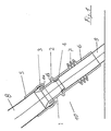
- the bellows designated 10 has a flexible trained offset section 1 with associated ends 1a and 1b.
- the end 1a is via a joint 3 with the End 5 of the bellows 10 mechanically connected, this End 5 the outer diameter of a feed pipe 8 tightly encloses.
- the inlet joint 3 be arranged in the interior of the feed pipe.
- the other End 1b of the offset section 1 is in the same way via a joint 2 with the other end 6 of the bellows 10 mechanically connected, this end 6 an additional Crumple zone 7 and the outer diameter of one Drain pipe 9 encloses firmly.
- the joint 2 is preferably protected by an annular lip seal 4.
Landscapes
- Engineering & Computer Science (AREA)
- Aviation & Aerospace Engineering (AREA)
- General Engineering & Computer Science (AREA)
- Mechanical Engineering (AREA)
- Joints Allowing Movement (AREA)
Abstract
Description
- daß das zulaufseitige Gelenk im Inneren des Zuleitungsrohres angeordnet ist,
- daß das dem Ableitungsrohr benachbarte Gelenk durch eine ringförmige Lippendichtung geschützt ist,
- daß der Übergang von der flexiblen Versatzstrecke zum rohrförmigen, dem Ableitungsrohr benachbarten Ende des Faltenbalges nach dem Prinzip von sich überlappenden Dachschindeln ausgebildet ist, und
- daß das dem Ableitungsrohr benachbarten Ende des Faltenbalges eine zusätzliche Knautschzone aufweist.
- Fig. 1
- einen Faltenbalg, der ein Zuleitungsrohr mit einem Ableitungsrohr mechanisch fest verbindet, und
- Fig. 2
- einen Faltenbalg gemäß Fig. 1 mit einem Übergang nach dem Prinzip von sich überlappenden Dachschindeln.
- 1
- Versatzstrecke des Faltenbalges 1C
- 1a
- ein Ende der Versatzstrecke 1
- 1b
- anderes Ende der Versatzstrecke 1
- 2
- ablaufseitiges Gelenk
- 3
- zulaufseitiges Gelenk
- 4
- Lippendichtung
- 5
- zulaufseitiges Ende des Faltenbalges 10
- 6
- ablaufseitiges Ende des Faltenbalges 10
- 7
- Knautschzone des ablaufseitigen Endes 6
- 8
- Zuleitungsrohr
- 9
- Ableitungsrohr
- 10
- Faltenbalg
- 11
- Übergang gemäß überlappender Dachschindeln
Claims (5)
- Faltenbalg zur mechanischen Verbindung von zwei, in einem vorgegebenen Abstand zueinander angeordneten Rohren, die zur Weiterleitung von fließfähigen Medien vorgesehen sind, vorzugsweise von einem, in einem Flugzeug angeordneten Zuleitungsrohr und einem Ableitungsrohr für einen Drainmast, wobei die beiden rohrförmigen Enden des Faltenbalges jeweils ein Ende eines Rohres umschließen, dadurch gekennzeichnet, daß eine flexibel ausgebildete Versatzstrecke (1) vorgesehen ist, deren Enden (1a, 1b) über jeweils ein Gelenk (3 bzw.2) mit den rohrförmigen Enden (5 bzw. 6) des Faltenbalges (10) mechanisch fest verbunden sind.
- Faltenbalg nach Anspruch 1, dadurch gekennzeichnet, daß das zulaufseitige Gelenk (3) im Inneren des Zuleitungsrohres (8) angeordnet ist.
- Faltenbalg nach Anspruch 1, dadurch gekennzeichnet, daß das dem Ableitungsrohr (9) benachbarte Gelenk (2) durch eine ringförmige Lippendichtung (4) geschützt ist.
- Faltenbalg nach Anspruch 1, dadurch gekennzeichnet, daß der Übergang von der flexiblen Versatzstrecke (1) zum rohrförmigen, dem Ableitungsrohr (9) benachbarten Ende (6) des Faltenbalges (10) nach dem Prinzip von sich überlappenden Dachschindeln (11) ausgebildet ist.
- Faltenbalg nach Anspruch 4, dadurch gekennzeichnet, daß das dem Ableitungsrohr (9) benachbarte Ende (6) des Faltenbalges (10) eine zusätzliche Knautschzone (7) aufweist.
Applications Claiming Priority (2)
| Application Number | Priority Date | Filing Date | Title |
|---|---|---|---|
| DE10301374A DE10301374B4 (de) | 2003-01-16 | 2003-01-16 | Faltenbalg zur mechanischen Verbindung von zwei, in einem vorgegebenen Abstand angeordneten Rohren |
| DE10301374 | 2003-01-16 |
Publications (2)
| Publication Number | Publication Date |
|---|---|
| EP1439122A1 true EP1439122A1 (de) | 2004-07-21 |
| EP1439122B1 EP1439122B1 (de) | 2006-01-04 |
Family
ID=32519988
Family Applications (1)
| Application Number | Title | Priority Date | Filing Date |
|---|---|---|---|
| EP03027919A Expired - Lifetime EP1439122B1 (de) | 2003-01-16 | 2003-12-04 | Faltenbalg zur mechanischen Verbindung von zwei, in einem vorgegebenen Abstand zueinander angeordneten Rohren |
Country Status (4)
| Country | Link |
|---|---|
| US (1) | US6854769B2 (de) |
| EP (1) | EP1439122B1 (de) |
| AT (1) | ATE314963T1 (de) |
| DE (2) | DE10301374B4 (de) |
Cited By (2)
| Publication number | Priority date | Publication date | Assignee | Title |
|---|---|---|---|---|
| EP2279946A4 (de) * | 2008-05-30 | 2013-08-21 | Airbus Operations Sl | Konfiguration der pneumatikeinheit im hinteren bereich eines flugzeugs |
| EP3889485A3 (de) * | 2020-03-31 | 2021-12-29 | Airbus Operations GmbH | Abwassertankanordnung für ein flugzeug |
Families Citing this family (15)
| Publication number | Priority date | Publication date | Assignee | Title |
|---|---|---|---|---|
| DE102005022855B4 (de) * | 2005-05-18 | 2012-12-20 | Airbus Operations Gmbh | Grauwasserentsorgung bei Flugzeugen |
| US7731127B2 (en) | 2005-05-18 | 2010-06-08 | Airbus Deutschland Gmbh | Drain mast connector |
| US8297660B2 (en) * | 2007-07-07 | 2012-10-30 | Electrolux Home Products Corporation N.V. | Water-conducting household appliance |
| NZ565256A (en) * | 2008-01-22 | 2008-09-26 | Imp Products Ltd | Improved pipe diversion device and method |
| JP5050982B2 (ja) * | 2008-04-24 | 2012-10-17 | セイコーエプソン株式会社 | 流体噴射装置および手術用メス |
| ES2398890B1 (es) * | 2011-01-27 | 2014-04-29 | Airbus Operations, S.L. | Dispositivo de drenaje de apu flexible y resistente al fuego |
| DE102011082743A1 (de) * | 2011-09-15 | 2013-03-21 | Robert Bosch Gmbh | Brennstoffverteiler |
| CA2902054C (en) * | 2013-03-06 | 2020-07-28 | Bombardier Inc. | Aircraft drainage system |
| US9315253B2 (en) | 2013-09-18 | 2016-04-19 | Goodrich Corporation | Drain masts |
| EP3028941B1 (de) * | 2014-12-03 | 2019-07-10 | AIRBUS HELICOPTERS DEUTSCHLAND GmbH | Vorrichgung zur drainage von flüssigkeit aus einem hohlraum in einem fahrzeug |
| US10197207B2 (en) * | 2015-01-22 | 2019-02-05 | Hamilton Sundstrand Corporation | Conductive elastomeric flexible coupling |
| US10539102B2 (en) * | 2016-03-08 | 2020-01-21 | K&N Engineering, Inc. | Pro stock fuel injection air intake assembly |
| CN105673972B (zh) * | 2016-03-16 | 2017-11-17 | 安徽万瑞冷电科技有限公司 | 真空管道 |
| GB201610080D0 (en) * | 2016-06-09 | 2016-07-27 | Rolls Royce Plc | Multi-stage compressor with multiple bleed plenums |
| CN108411782A (zh) * | 2018-05-11 | 2018-08-17 | 安徽瑞仕达预应力设备有限责任公司 | 偏心接头及线管和分丝管的连接结构 |
Citations (3)
| Publication number | Priority date | Publication date | Assignee | Title |
|---|---|---|---|---|
| FR1444034A (fr) * | 1965-05-07 | 1966-07-01 | Calorstat | Dispositif d'accouplement pour éléments tubulaires |
| US5480194A (en) * | 1994-11-21 | 1996-01-02 | Boa Ag | Metal expansion joint vibration absorber apparatus for pipe systems |
| EP1033482A1 (de) * | 1999-03-04 | 2000-09-06 | Sango Co., Ltd. | Wellrohr |
Family Cites Families (10)
| Publication number | Priority date | Publication date | Assignee | Title |
|---|---|---|---|---|
| FR1312303A (fr) * | 1962-01-24 | 1962-12-14 | Us Rubber Co | Raccord télescopique pour tuyaux à déplacements axiaux |
| US3473833A (en) * | 1967-12-28 | 1969-10-21 | Nat Distillers Chem Corp | Plastic pipe coupling |
| US3768457A (en) * | 1972-12-13 | 1973-10-30 | American Standard Inc | Fireplace construction |
| IL64379A (en) * | 1981-11-26 | 1989-01-31 | Plasson Maagan Michael Ind Ltd | Tube connection fittings |
| US4679827A (en) * | 1984-12-28 | 1987-07-14 | Thomas & Betts Corporation | Raintight and oiltight connector for flexible conduit |
| DE3530972A1 (de) * | 1985-08-30 | 1987-03-05 | Agintec Ag | Kompensator |
| US5269570A (en) * | 1991-04-17 | 1993-12-14 | Nunley Dwight S | Flexible casing for well boreholes |
| DE4318343A1 (de) * | 1993-06-02 | 1994-12-08 | Iwk Regler Kompensatoren | Vorrichtung zum Dämpfen von Schwingungen in einer Abgasanlage eines Fahrzeugs |
| JPH10148286A (ja) * | 1996-11-18 | 1998-06-02 | Mitsubishi Plastics Ind Ltd | 管継手 |
| DE19824095C2 (de) * | 1998-05-29 | 2000-05-18 | Iwk Regler Kompensatoren | Flexibles Leitungselement |
-
2003
- 2003-01-16 DE DE10301374A patent/DE10301374B4/de not_active Expired - Fee Related
- 2003-12-04 DE DE50302109T patent/DE50302109D1/de not_active Expired - Lifetime
- 2003-12-04 AT AT03027919T patent/ATE314963T1/de not_active IP Right Cessation
- 2003-12-04 EP EP03027919A patent/EP1439122B1/de not_active Expired - Lifetime
-
2004
- 2004-01-14 US US10/757,758 patent/US6854769B2/en not_active Expired - Fee Related
Patent Citations (3)
| Publication number | Priority date | Publication date | Assignee | Title |
|---|---|---|---|---|
| FR1444034A (fr) * | 1965-05-07 | 1966-07-01 | Calorstat | Dispositif d'accouplement pour éléments tubulaires |
| US5480194A (en) * | 1994-11-21 | 1996-01-02 | Boa Ag | Metal expansion joint vibration absorber apparatus for pipe systems |
| EP1033482A1 (de) * | 1999-03-04 | 2000-09-06 | Sango Co., Ltd. | Wellrohr |
Cited By (2)
| Publication number | Priority date | Publication date | Assignee | Title |
|---|---|---|---|---|
| EP2279946A4 (de) * | 2008-05-30 | 2013-08-21 | Airbus Operations Sl | Konfiguration der pneumatikeinheit im hinteren bereich eines flugzeugs |
| EP3889485A3 (de) * | 2020-03-31 | 2021-12-29 | Airbus Operations GmbH | Abwassertankanordnung für ein flugzeug |
Also Published As
| Publication number | Publication date |
|---|---|
| US6854769B2 (en) | 2005-02-15 |
| DE50302109D1 (de) | 2006-03-30 |
| US20040146339A1 (en) | 2004-07-29 |
| ATE314963T1 (de) | 2006-02-15 |
| DE10301374A1 (de) | 2004-08-05 |
| DE10301374B4 (de) | 2005-07-07 |
| EP1439122B1 (de) | 2006-01-04 |
Similar Documents
| Publication | Publication Date | Title |
|---|---|---|
| EP1439122B1 (de) | Faltenbalg zur mechanischen Verbindung von zwei, in einem vorgegebenen Abstand zueinander angeordneten Rohren | |
| DE102009056975B3 (de) | Rohrförmiges Bauteil | |
| DE2911575A1 (de) | Zugfeste rohrkupplung | |
| DE2718208A1 (de) | Muffenverbindung fuer rohre | |
| DE1506848B2 (de) | Rohrleitung fuer den pneumatischen oder hydraulischen transport kurzer, gleichartiger materialpfropfen | |
| DE3527685C2 (de) | ||
| CH665465A5 (de) | Rohrverbindung fuer kunststoffrohre. | |
| DE3436040C2 (de) | ||
| CH707521A2 (de) | Verbindungsvorrichtung für zwei getrennte Leitungsenden zur Bildung einer Förderleitung für den Transport eines schüttfähigen, flüssigen und/oder gasförmigen Produkts. | |
| DE69527615T2 (de) | Biegsame verbindung | |
| EP1027501A1 (de) | Korrosionsschutzeinrichtung für ein seil | |
| DE4390465C2 (de) | Isolierrohrsystem | |
| EP1118811A2 (de) | Flexibles Leitungselement mit einer an mindestens einem Ende angebrachten Anschlussvorrichtung | |
| DE3239342A1 (de) | Bohrgestaenge | |
| DE842437C (de) | Abwinkelbare Rohrverbindung | |
| AT398335B (de) | Rohrleitung aus mehreren über in axialer richtung wirkenden klammern, verbundenen, mit flanschen versehenen rohrstücken | |
| DE3110217C2 (de) | Schneckenförderer | |
| CH680748A5 (en) | Flexible connection tube for water connections in water heater - has corrugated tube with end connection flanges formed by compressed corrugations | |
| DE1300623B (de) | Aus Kunststoff bestehendes Gehaeuse eines Zentrifugalventilators | |
| DE2038697C3 (de) | Rohrkupplung | |
| DE8909973U1 (de) | Breitbandschelle zur Verbindung zweier Rohre | |
| DE9308012U1 (de) | T-förmiges Rohrstück | |
| DE3121056C1 (de) | Mehrteiliger Ausbauring | |
| DE2730391B2 (de) | Längenveränderliche Rohrverbindung | |
| DE8912208U1 (de) | Lösbare, quer- und längskraftschlüssige Rohrverbindung |
Legal Events
| Date | Code | Title | Description |
|---|---|---|---|
| PUAI | Public reference made under article 153(3) epc to a published international application that has entered the european phase |
Free format text: ORIGINAL CODE: 0009012 |
|
| AK | Designated contracting states |
Kind code of ref document: A1 Designated state(s): AT BE BG CH CY CZ DE DK EE ES FI FR GB GR HU IE IT LI LU MC NL PT RO SE SI SK TR |
|
| AX | Request for extension of the european patent |
Extension state: AL LT LV MK |
|
| 17P | Request for examination filed |
Effective date: 20050121 |
|
| AKX | Designation fees paid |
Designated state(s): AT BE BG CH CY CZ DE DK EE ES FI FR GB GR HU IE IT LI LU MC NL PT RO SE SI SK TR |
|
| GRAP | Despatch of communication of intention to grant a patent |
Free format text: ORIGINAL CODE: EPIDOSNIGR1 |
|
| GRAS | Grant fee paid |
Free format text: ORIGINAL CODE: EPIDOSNIGR3 |
|
| GRAA | (expected) grant |
Free format text: ORIGINAL CODE: 0009210 |
|
| AK | Designated contracting states |
Kind code of ref document: B1 Designated state(s): AT BE BG CH CY CZ DE DK EE ES FI FR GB GR HU IE IT LI LU MC NL PT RO SE SI SK TR |
|
| PG25 | Lapsed in a contracting state [announced via postgrant information from national office to epo] |
Ref country code: IT Free format text: LAPSE BECAUSE OF FAILURE TO SUBMIT A TRANSLATION OF THE DESCRIPTION OR TO PAY THE FEE WITHIN THE PRESCRIBED TIME-LIMIT;WARNING: LAPSES OF ITALIAN PATENTS WITH EFFECTIVE DATE BEFORE 2007 MAY HAVE OCCURRED AT ANY TIME BEFORE 2007. THE CORRECT EFFECTIVE DATE MAY BE DIFFERENT FROM THE ONE RECORDED. Effective date: 20060104 Ref country code: FI Free format text: LAPSE BECAUSE OF FAILURE TO SUBMIT A TRANSLATION OF THE DESCRIPTION OR TO PAY THE FEE WITHIN THE PRESCRIBED TIME-LIMIT Effective date: 20060104 Ref country code: SI Free format text: LAPSE BECAUSE OF FAILURE TO SUBMIT A TRANSLATION OF THE DESCRIPTION OR TO PAY THE FEE WITHIN THE PRESCRIBED TIME-LIMIT Effective date: 20060104 Ref country code: SK Free format text: LAPSE BECAUSE OF FAILURE TO SUBMIT A TRANSLATION OF THE DESCRIPTION OR TO PAY THE FEE WITHIN THE PRESCRIBED TIME-LIMIT Effective date: 20060104 Ref country code: NL Free format text: LAPSE BECAUSE OF FAILURE TO SUBMIT A TRANSLATION OF THE DESCRIPTION OR TO PAY THE FEE WITHIN THE PRESCRIBED TIME-LIMIT Effective date: 20060104 Ref country code: RO Free format text: LAPSE BECAUSE OF FAILURE TO SUBMIT A TRANSLATION OF THE DESCRIPTION OR TO PAY THE FEE WITHIN THE PRESCRIBED TIME-LIMIT Effective date: 20060104 Ref country code: IE Free format text: LAPSE BECAUSE OF FAILURE TO SUBMIT A TRANSLATION OF THE DESCRIPTION OR TO PAY THE FEE WITHIN THE PRESCRIBED TIME-LIMIT Effective date: 20060104 |
|
| REG | Reference to a national code |
Ref country code: GB Ref legal event code: FG4D Free format text: NOT ENGLISH |
|
| REG | Reference to a national code |
Ref country code: CH Ref legal event code: EP |
|
| REG | Reference to a national code |
Ref country code: IE Ref legal event code: FG4D Free format text: LANGUAGE OF EP DOCUMENT: GERMAN |
|
| REF | Corresponds to: |
Ref document number: 50302109 Country of ref document: DE Date of ref document: 20060330 Kind code of ref document: P |
|
| PG25 | Lapsed in a contracting state [announced via postgrant information from national office to epo] |
Ref country code: SE Free format text: LAPSE BECAUSE OF FAILURE TO SUBMIT A TRANSLATION OF THE DESCRIPTION OR TO PAY THE FEE WITHIN THE PRESCRIBED TIME-LIMIT Effective date: 20060404 Ref country code: BG Free format text: LAPSE BECAUSE OF FAILURE TO SUBMIT A TRANSLATION OF THE DESCRIPTION OR TO PAY THE FEE WITHIN THE PRESCRIBED TIME-LIMIT Effective date: 20060404 Ref country code: DK Free format text: LAPSE BECAUSE OF FAILURE TO SUBMIT A TRANSLATION OF THE DESCRIPTION OR TO PAY THE FEE WITHIN THE PRESCRIBED TIME-LIMIT Effective date: 20060404 |
|
| GBT | Gb: translation of ep patent filed (gb section 77(6)(a)/1977) |
Effective date: 20060316 |
|
| PG25 | Lapsed in a contracting state [announced via postgrant information from national office to epo] |
Ref country code: ES Free format text: LAPSE BECAUSE OF FAILURE TO SUBMIT A TRANSLATION OF THE DESCRIPTION OR TO PAY THE FEE WITHIN THE PRESCRIBED TIME-LIMIT Effective date: 20060415 |
|
| PG25 | Lapsed in a contracting state [announced via postgrant information from national office to epo] |
Ref country code: PT Free format text: LAPSE BECAUSE OF FAILURE TO SUBMIT A TRANSLATION OF THE DESCRIPTION OR TO PAY THE FEE WITHIN THE PRESCRIBED TIME-LIMIT Effective date: 20060605 |
|
| NLV1 | Nl: lapsed or annulled due to failure to fulfill the requirements of art. 29p and 29m of the patents act | ||
| REG | Reference to a national code |
Ref country code: IE Ref legal event code: FD4D |
|
| ET | Fr: translation filed | ||
| PLBE | No opposition filed within time limit |
Free format text: ORIGINAL CODE: 0009261 |
|
| STAA | Information on the status of an ep patent application or granted ep patent |
Free format text: STATUS: NO OPPOSITION FILED WITHIN TIME LIMIT |
|
| 26N | No opposition filed |
Effective date: 20061005 |
|
| PG25 | Lapsed in a contracting state [announced via postgrant information from national office to epo] |
Ref country code: BE Free format text: LAPSE BECAUSE OF NON-PAYMENT OF DUE FEES Effective date: 20061231 Ref country code: MC Free format text: LAPSE BECAUSE OF NON-PAYMENT OF DUE FEES Effective date: 20061231 |
|
| BERE | Be: lapsed |
Owner name: AIRBUS DEUTSCHLAND G.M.B.H. Effective date: 20061231 |
|
| PG25 | Lapsed in a contracting state [announced via postgrant information from national office to epo] |
Ref country code: AT Free format text: LAPSE BECAUSE OF NON-PAYMENT OF DUE FEES Effective date: 20061204 |
|
| PG25 | Lapsed in a contracting state [announced via postgrant information from national office to epo] |
Ref country code: CZ Free format text: LAPSE BECAUSE OF FAILURE TO SUBMIT A TRANSLATION OF THE DESCRIPTION OR TO PAY THE FEE WITHIN THE PRESCRIBED TIME-LIMIT Effective date: 20060104 Ref country code: GR Free format text: LAPSE BECAUSE OF FAILURE TO SUBMIT A TRANSLATION OF THE DESCRIPTION OR TO PAY THE FEE WITHIN THE PRESCRIBED TIME-LIMIT Effective date: 20060405 |
|
| PG25 | Lapsed in a contracting state [announced via postgrant information from national office to epo] |
Ref country code: EE Free format text: LAPSE BECAUSE OF FAILURE TO SUBMIT A TRANSLATION OF THE DESCRIPTION OR TO PAY THE FEE WITHIN THE PRESCRIBED TIME-LIMIT Effective date: 20060104 |
|
| PG25 | Lapsed in a contracting state [announced via postgrant information from national office to epo] |
Ref country code: LU Free format text: LAPSE BECAUSE OF NON-PAYMENT OF DUE FEES Effective date: 20061204 Ref country code: TR Free format text: LAPSE BECAUSE OF FAILURE TO SUBMIT A TRANSLATION OF THE DESCRIPTION OR TO PAY THE FEE WITHIN THE PRESCRIBED TIME-LIMIT Effective date: 20060104 Ref country code: HU Free format text: LAPSE BECAUSE OF FAILURE TO SUBMIT A TRANSLATION OF THE DESCRIPTION OR TO PAY THE FEE WITHIN THE PRESCRIBED TIME-LIMIT Effective date: 20060705 |
|
| REG | Reference to a national code |
Ref country code: CH Ref legal event code: PL |
|
| PG25 | Lapsed in a contracting state [announced via postgrant information from national office to epo] |
Ref country code: LI Free format text: LAPSE BECAUSE OF NON-PAYMENT OF DUE FEES Effective date: 20071231 Ref country code: CH Free format text: LAPSE BECAUSE OF NON-PAYMENT OF DUE FEES Effective date: 20071231 |
|
| PG25 | Lapsed in a contracting state [announced via postgrant information from national office to epo] |
Ref country code: CY Free format text: LAPSE BECAUSE OF FAILURE TO SUBMIT A TRANSLATION OF THE DESCRIPTION OR TO PAY THE FEE WITHIN THE PRESCRIBED TIME-LIMIT Effective date: 20060104 |
|
| REG | Reference to a national code |
Ref country code: FR Ref legal event code: CD Owner name: AIRBUS OPERATIONS GMBH Effective date: 20111118 |
|
| PGFP | Annual fee paid to national office [announced via postgrant information from national office to epo] |
Ref country code: DE Payment date: 20131220 Year of fee payment: 11 Ref country code: GB Payment date: 20131219 Year of fee payment: 11 |
|
| PGFP | Annual fee paid to national office [announced via postgrant information from national office to epo] |
Ref country code: FR Payment date: 20131220 Year of fee payment: 11 |
|
| REG | Reference to a national code |
Ref country code: DE Ref legal event code: R119 Ref document number: 50302109 Country of ref document: DE |
|
| GBPC | Gb: european patent ceased through non-payment of renewal fee |
Effective date: 20141204 |
|
| REG | Reference to a national code |
Ref country code: FR Ref legal event code: ST Effective date: 20150831 |
|
| PG25 | Lapsed in a contracting state [announced via postgrant information from national office to epo] |
Ref country code: DE Free format text: LAPSE BECAUSE OF NON-PAYMENT OF DUE FEES Effective date: 20150701 Ref country code: GB Free format text: LAPSE BECAUSE OF NON-PAYMENT OF DUE FEES Effective date: 20141204 |
|
| PG25 | Lapsed in a contracting state [announced via postgrant information from national office to epo] |
Ref country code: FR Free format text: LAPSE BECAUSE OF NON-PAYMENT OF DUE FEES Effective date: 20141231 |