EP1438762B1 - Production continue de membranes recouvertes d'un catalyseur - Google Patents
Production continue de membranes recouvertes d'un catalyseur Download PDFInfo
- Publication number
- EP1438762B1 EP1438762B1 EP02776282A EP02776282A EP1438762B1 EP 1438762 B1 EP1438762 B1 EP 1438762B1 EP 02776282 A EP02776282 A EP 02776282A EP 02776282 A EP02776282 A EP 02776282A EP 1438762 B1 EP1438762 B1 EP 1438762B1
- Authority
- EP
- European Patent Office
- Prior art keywords
- electrode
- coating composition
- membrane
- polymer
- electrocatalyst
- Prior art date
- Legal status (The legal status is an assumption and is not a legal conclusion. Google has not performed a legal analysis and makes no representation as to the accuracy of the status listed.)
- Expired - Lifetime
Links
Images
Classifications
-
- H—ELECTRICITY
- H01—ELECTRIC ELEMENTS
- H01M—PROCESSES OR MEANS, e.g. BATTERIES, FOR THE DIRECT CONVERSION OF CHEMICAL ENERGY INTO ELECTRICAL ENERGY
- H01M4/00—Electrodes
- H01M4/86—Inert electrodes with catalytic activity, e.g. for fuel cells
- H01M4/88—Processes of manufacture
- H01M4/8803—Supports for the deposition of the catalytic active composition
- H01M4/881—Electrolytic membranes
-
- H—ELECTRICITY
- H01—ELECTRIC ELEMENTS
- H01M—PROCESSES OR MEANS, e.g. BATTERIES, FOR THE DIRECT CONVERSION OF CHEMICAL ENERGY INTO ELECTRICAL ENERGY
- H01M4/00—Electrodes
- H01M4/86—Inert electrodes with catalytic activity, e.g. for fuel cells
- H01M4/90—Selection of catalytic material
- H01M4/92—Metals of platinum group
- H01M4/925—Metals of platinum group supported on carriers, e.g. powder carriers
- H01M4/926—Metals of platinum group supported on carriers, e.g. powder carriers on carbon or graphite
-
- H—ELECTRICITY
- H01—ELECTRIC ELEMENTS
- H01M—PROCESSES OR MEANS, e.g. BATTERIES, FOR THE DIRECT CONVERSION OF CHEMICAL ENERGY INTO ELECTRICAL ENERGY
- H01M8/00—Fuel cells; Manufacture thereof
- H01M8/10—Fuel cells with solid electrolytes
- H01M8/1004—Fuel cells with solid electrolytes characterised by membrane-electrode assemblies [MEA]
-
- H—ELECTRICITY
- H01—ELECTRIC ELEMENTS
- H01M—PROCESSES OR MEANS, e.g. BATTERIES, FOR THE DIRECT CONVERSION OF CHEMICAL ENERGY INTO ELECTRICAL ENERGY
- H01M4/00—Electrodes
- H01M4/86—Inert electrodes with catalytic activity, e.g. for fuel cells
- H01M4/90—Selection of catalytic material
- H01M4/92—Metals of platinum group
-
- Y—GENERAL TAGGING OF NEW TECHNOLOGICAL DEVELOPMENTS; GENERAL TAGGING OF CROSS-SECTIONAL TECHNOLOGIES SPANNING OVER SEVERAL SECTIONS OF THE IPC; TECHNICAL SUBJECTS COVERED BY FORMER USPC CROSS-REFERENCE ART COLLECTIONS [XRACs] AND DIGESTS
- Y02—TECHNOLOGIES OR APPLICATIONS FOR MITIGATION OR ADAPTATION AGAINST CLIMATE CHANGE
- Y02E—REDUCTION OF GREENHOUSE GAS [GHG] EMISSIONS, RELATED TO ENERGY GENERATION, TRANSMISSION OR DISTRIBUTION
- Y02E60/00—Enabling technologies; Technologies with a potential or indirect contribution to GHG emissions mitigation
- Y02E60/30—Hydrogen technology
- Y02E60/50—Fuel cells
-
- Y—GENERAL TAGGING OF NEW TECHNOLOGICAL DEVELOPMENTS; GENERAL TAGGING OF CROSS-SECTIONAL TECHNOLOGIES SPANNING OVER SEVERAL SECTIONS OF THE IPC; TECHNICAL SUBJECTS COVERED BY FORMER USPC CROSS-REFERENCE ART COLLECTIONS [XRACs] AND DIGESTS
- Y02—TECHNOLOGIES OR APPLICATIONS FOR MITIGATION OR ADAPTATION AGAINST CLIMATE CHANGE
- Y02P—CLIMATE CHANGE MITIGATION TECHNOLOGIES IN THE PRODUCTION OR PROCESSING OF GOODS
- Y02P70/00—Climate change mitigation technologies in the production process for final industrial or consumer products
- Y02P70/50—Manufacturing or production processes characterised by the final manufactured product
Definitions
- This invention relates to a continuous method for the production of catalyst coated membranes for use in electrochemical cells, especially catalyst coated membranes for use in fuel cells.
- SPE solid polymer electrolyte
- An SPE cell typically employs a membrane of a cation exchange polymer that serves as a physical separator between the anode and cathode while also serving as an electrolyte.
- SPE cells can be operated as electrolytic cells for the production of electrochemical products or they may be operated as fuel cells.
- Fuel cells are electrochemical cells that convert reactants, namely fuel and oxidant fluid streams, to generate electric power and reaction products.
- reactants namely fuel and oxidant fluid streams
- a broad range of reactants can be used in fuel cells and such reactants may be delivered in gaseous or liquid streams.
- the fuel stream may be substantially pure hydrogen gas, a gaseous hydrogen-containing reformate stream, or an aqueous alcohol, for example methanol in a direct methanol fuel cell (DMFC).
- the oxidant may, for example, be substantially pure oxygen or a dilute oxygen stream such as air.
- the solid polymer electrolyte membrane is typically perfluorinated sulfonic acid polymer membrane in acid form.
- fuel cells are often referred to as proton exchange membrane ("PEM") fuel cells.
- the membrane is disposed between and in contact with the anode and the cathode.
- Electrocatalysts in the anode and the cathode typically induce the desired electrochemical reactions and may be, for example, a metal black, an alloy or a metal catalyst supported on a substrate, e.g., platinum on carbon.
- SPE fuel cells typically also comprise a porous, electrically conductive sheet material that is in electrical contact with each of the electrodes, and permit diffusion of the reactants to the electrodes.
- this porous, conductive sheet material is sometimes referred to as a gas diffusion layer and is suitably provided by a carbon fiber paper or carbon cloth.
- An assembly including the membrane, anode and cathode, and gas diffusion layers for each electrode, is sometimes referred to as a membrane electrode assembly ("MEA").
- MEA membrane electrode assembly
- Bipolar plates made of a conductive material and providing flow fields for the reactants, are placed between a number of adjacent MEAs. A number of MEAs and bipolar plates are assembled in this manner to provide a fuel cell stack.
- Effective electrocatalyst sites have several desirable characteristics: (1) the sites are accessible to the reactant, (2) the sites are electrically connected to the gas diffusion layer, and (3) the sites are ionically connected to the fuel cell electrolyte.
- ion exchange polymers are often incorporated into the electrodes.
- incorporation of ion exchange polymer into the electrodes can also have beneficial effects with liquid feed fuels. For example, in a direct methanol fuel cell, ion exchange polymer in the anode makes it more wettable by the liquid feed stream in order to improve access of the reactant to the electrocatalyst sites.
- hydrophobic components such as polytetrafluoroethylene (“PTFE”) are typically employed, in part, to render electrodes less wettable and to prevent "flooding".
- PTFE polytetrafluoroethylene
- Flooding generally refers to a situation where the pores in an electrode become filled with water formed as a reaction product, such that the flow of the gaseous reactant through the electrode becomes impeded.
- the electrodes are formed on the gas diffusion layers by coating electrocatalyst and dispersed particles of PTFE in a suitable liquid medium onto the gas diffusion layer, e.g., carbon fiber paper.
- a suitable liquid medium e.g., carbon fiber paper.
- the carbon fiber paper with the electrodes attached and a membrane are then assembled into an MEA by pressing such that the electrodes are in contact with the membrane.
- MEA's of this type it is difficult to establish the desired ionic contact between the electrode and the membrane due to the lack of intimate contact. As a result, the interfacial resistance may be higher than desired.
- electrodes are formed onto the surface of the membrane.
- a membrane having electrodes so formed is often referred to as a catalyst coated membrane ("CCM").
- CCMs catalyst coated membrane
- CCMs Various manufacturing methods have been developed for manufacturing CCMs. Many of these processes have employed electrocatalyst coating slurries containing the electrocatalyst and the ion exchange polymer and, optionally, other materials such as a PTFE dispersion.
- the ion exchange polymer in the membrane itself, and in the electrocatalyst coating solution could be employed in either hydrolyzed or unhydrolyzed ion-exchange polymer (sulfonyl fluoride form when perfluorinated sulfonic acid polymer is used), and in the latter case, the polymer must be hydrolyzed during the manufacturing process.
- a "decal" is first made by depositing the electrocatalyst coating solution on another substrate, removing the solvent and then transferring and adhering the resulting decal to the membrane. These techniques also can produce good results but mechanical handling and placement of decals on the membrane are difficult to perform in high volume manufacturing operations.
- a process is needed which is suitable for the high volume production of catalyst coated membranes and which avoids problems associated with prior art processes. Further, a process is needed which is suitable for the direct application of an electrocatalyst coating composition to a membrane in hydrolyzed form which avoids the swelling problems associated with known processes and which does not require complicated pre-treatment or post-treatment process steps.
- the invention provides a process for manufacturing a catalyst coated membrane comprising:
- the polymeric solution or dispersion is selected from the group consisting of a highly fluorinated ionomer, a precursor thereof, a mixture of the highly fluorinated ionomer with a fluorinated polymer, for example, polytetrafluoroethylene (PTFE) fibrils, and a mixture of the precursor of the highly fluorinated ionomer with a fluorinated polymers.
- a highly fluorinated ionomer for example, polytetrafluoroethylene (PTFE) fibrils
- PTFE polytetrafluoroethylene
- the invention further comprises the step of chemically treating the precursor of the highly fluorinated ionomer to convert it to its ionomeric form.
- the invention also further comprises applying at least one nonelectrocatalytic coating composition to form a nonelectrocatalytic layer over at least part of the same area of the substrate which is covered by an electrode layer.
- the invention also provides a process wherein applying at least one electrocatalyst coating composition is accomplished by flexographic printing.
- the invention provides for the application of the electrocatalyst coating composition and drying steps to be repeated to form multiple electrode layers covering the same part of the surface of the substrate.
- the process advantageously provides multiple electrode layers that vary in composition.
- the application of the electrocatalyst coating composition may advantageously provide an electrode layer with a predetermined nonuniform distribution of electrocatalyst across the electrode layer.
- the process in accordance with the invention is extremely well-suited to high volume commercial manufacture of catalyst coated membranes. Flexographic printing provide thin, well-distributed layers of the electrocatalyst composition and avoid problems associated with coating techniques that employ large quantities of solvent. Alternately, pad printing may be used to apply the electrocatalyst coating composition.
- the process is extremely versatile and can provide electrodes in any of a wide variety of shapes and patterns and, if desired, can have electrocatalyst or other electrode materials that vary in amount or composition across the electrode, through the thickness of the electrode or both.
- This invention provides a process for manufacturing catalyst coated membranes that employs, for example, flexographic printing technology to apply an electrocatalyst coating composition onto a dimensionally stable, temporary substrate, drying to form a first electrode, followed by application of a membrane forming solution or dispersion, drying to form a polymer membrane, application of a second electrocatalyst coating composition, and drying the same to form a sandwich comprising the temporary substrate, the first electrode, the polymer membrane, and the second electrode.
- the temporary substrate is then removed to form the catalyst coated membrane.
- flexographic printing technology to apply an electrocatalyst coating composition onto a dimensionally stable, temporary substrate, drying to form a first electrode, followed by application of a membrane forming solution or dispersion, drying to form a polymer membrane, application of a second electrocatalyst coating composition, and drying the same to form a sandwich comprising the temporary substrate, the first electrode, the polymer membrane, and the second electrode.
- the temporary substrate is then removed to form the catalyst coated membrane
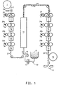
- a dimesionally stable substrate 2 is unwound from a roll unwind 1 and optionally fed past a treating station 2a , and past at least one printing station 3 , typically a flexographic printing station, and drying station 7 .
- Infrared or forced air convection dryers of the type typically used in the printing or film coating industry would be used. Vendors of such equipment include Mark-Andy or Pemarco from basic printing or Black - Clausen or Bachoff & Meyer from film coating.
- the dimensionally stable temporary substrate 2 may be treated with processes, such as corona or electric discharge plasma treatment processes or agents such as primer sprays or sub-coat layers that are either non-functional or can be removed in downstream post-processing.
- the temporary substrate has to adhere to the sandwich formed on it during the process steps, but needs to be easily separated from the sandwich in step (g) without destroying the sandwich.
- a treatment for the temporary substrate is an open array of Nafion® straight fluoro-ionomer "dots" printed first on the substrate.
- Additional printing stations 3a, 3b to 3n and drying stations 7a, 7b to 7n may be present to apply additional electrocatalyst coating composition 20a, 20b, 20n to the temporary substrate 2 .
- the temporary substrate 2 with first electrode 21 formed thereon is led past the membrane forming solution or dispersion coating station 30 , wherein the membrane forming dispersion 8 , such as a polymeric solution or dispersion, is fed to the application device 10 , typically a coating extrusion die or a knife edge applicator, through a precision metering device 9 , such as a gear pump, and applied, typically coated or extruded, onto the temporary substrate 2 carrying the first electrode 21 .
- the application device 10 typically a coating extrusion die or a knife edge applicator
- a precision metering device 9 such as a gear pump
- the coated temporary substrate is then fed through a dryer 11 to form the membrane film 22 and the dried coated structure is then fed past at least one additional printing station 3 , typically a flexographic printing station, with electrocatalyst coating composition 24 , and drying station 7 to form a second electrode 23 on the membrane 22 .
- Additional printing stations 3a, 3b to 3n and drying stations 7a, 7b to 7n may be present to apply additional electrocatalyst coating compositions 24a, 24b, 24n to form a sandwich comprised of the second electrode 23 , the membrane 22 , the first electrode 21 and the temporary substrate 2 .
- Electrocatalyst coating compositions 20a, 20b, and 20n used to form the first electrode may be the same or different from electrocatalyst coating compositions 24a, 24b , and 24n used to form the second electrode.
- the temporary support 2 is then removed, typically peeled off the sandwich, leaving a catalyst coated membrane comprised of at least a first electrode 21 , a polymer membrane 22 and at least a second electrode 23 .
- This sandwich may then be chopped into discrete sized pieces at chopping station 13 of the type used for high value plastic sheeting such as X-Ray film, ink jet transparency stock etc.
- the chopped film may then be provided post treatments such as calendering, vapor treatment to affect water transport, or liquid extraction to remove trace residuals from any of the above earlier manufacturing steps. If the membrane dispersion or solution used was the precursor of the highly fluorinated ionomer, after application of the solution or dispersion the sandwich formed may be subjected to a chemical treatment to convert the precursor to the ionomer.
- Raised relief printing refers to processes which employ any of a variety of types of pre-formed plates which have raised areas which define the shape or pattern to be printed on a substrate.
- the raised areas of the plate are contacted by and become coated with a liquid electrocatalyst coating composition and then the raised areas are brought into contact with the membrane to deposit the composition onto the membrane. After drying, the shape or pattern defined by the raised areas is thereby transferred to membrane such as an ion exchange membrane to form an electrode layer.
- the relief printing is advantageously employed to form an electrode that is a build-up of multiple electrode layers.
- flexographic printing is the raised relief printing method employed.
- Flexographic printing is a well known printing technique used widely for packaging applications which employs elastomeric printing plates and is described in the Kirk-Othmer's Encyclopedia of Chemical Technology, 4th edition, 1996, John Wiley and Sons, New York, N.Y., volume 20, pages 62-128, especially pages 101-105.
- Such plates include sheet photopolymer plates, sheets made from liquid photopolymer and rubber printing plates.
- flexographic printing techniques that use photopolymer printing plates.
- the most preferred relief printing technique employs solid-sheet photopolymer plates such as the photopolymer flexographic printing plates sold by E.I. Du Pont de Nemours and Company of Wilmington, DE under the trademark Cyrel®.
- the flexographic method offers considerable benefits in cost, changeover, speed, and ease of printing on thin extensible substrates, such as ion exchange membranes and in the variety of electrodes that can be printed.
- the printed area may be of virtually any shape or design, regular or irregular, which can be transferred to the plate. Possible shapes include circles, ovals, polygons, and polygon having rounded corners.
- the shape may also be a pattern and may be intricate if desired.
- flexography may be used to print an electrode having a shape that coincides with pathway of fuel and oxidant flow fields.
- flexographic printing Multiple applications of the same or different coatings to the same area are easily accomplished using flexographic printing.
- flexographic printing In existing uses of flexography, it is common to apply multiple colors of ink in close registration and these techniques are well-suited to the printing of electrodes having overlying multiple layers.
- the composition and the amount of coating applied per application may be varied.
- the amount of coating applied at each pass may be varied across the coated area, i.e., length and/or width. Such variation need not be monotonic or continuous.
- the precision of flexographic printing has the further advantage of being very economical in the use of coating solution, which is particularly important for expensive electrocatalyst coating compositions.
- the process of the invention also typically includes the raised relief printing of a electrocatalyst coating composition onto the opposite surface of a membrane such as an ion exchange membrane to form at least one electrode layer covering at least a part of the opposite surface of the membrane in registration with the electrode layer first applied to the membrane.
- a membrane such as an ion exchange membrane
- the ability of flexographic printing to handle multiple applications in close registration is useful for this aspect of the invention.
- Cyrel® plates are thick layers of photopolymer uniformly deposited/bonded to 5 to 8 mil poly(ethylene terephthalate) (PET), then capped with a thin easy-release PET coversheet.
- PET poly(ethylene terephthalate)
- the photopolymer itself is a miscible mixture of about 65% acrylic polymer(s), 30% acrylic monomer(s), 5% dyes, initiators, and inhibitors.
- U.S. Patent Nos. 4,323,636 and 4,323,637 disclose photopolymer plates of this type.
- Negatives having images to create the raised areas on the plate can be designed by any suitable method and the creation of negatives electronically has been found to be especially useful.
- monomer polymerization occurs in select areas.
- unexposed, non-polymerized material may be removed by a variety of methods. The unexposed areas may be simply washed away by the action of a spray developer. Alternatively, the non-polymerized monomer may be liquefied by heating and then removed with an absorbent wipe material.
- a compressible photopolymer relief surface, made to photographic resolution is thus created. This relief surface serves to transfer electrocatalyst coating composition from a bulk applicator to a print applicator or to the substrate surface itself. Formation of an electrode layer occurs by simple wetting coupled with mechanical compression of the elastomeric plate.
- the pattern may be generated by known techniques including molding said rubber plate in the desired pattern or by laser ablation to yield the desired shape or pattern.
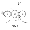
- FIG. 2 shows the use of flexographic press equipment to form electrodes on one side of a discrete length of membrane in accordance with the present invention.
- the electrocatalyst coating composition 20 is picked up by the anilox roll 4 .
- An anilox roll is a standardized tool of the printing industry consisting of a precision engraved cellular surfaced roll that draws out a uniform wet ink film from the ink reservoir. GMS anilox rolls have been found to be useful. Alternately, anilox rolls obtained from the Harper Corp. or Dean Printing Supplies or Pemarco Inc. that can apply even heavier coats (100 Ipi, 90 Ipi, 80 Ipi) with some tradeoff in uniformity and physical quality may be used.
- the wet ink thickness is controlled by the specific anilox cell geometry chosen.
- a portion of this ink film is transferred to a relief printing plate 5 having a plate impression 25 , such as a Cyrel® flexographic printing plate, positioned on a drum 14' .
- a membrane 2 such as a perfluorinated sulfonic acid polymer membrane in acid form, which is available under the trademark Nafion® from E. I. DuPont de Nemours and Company, is pressed by a rotating drum 6 against the mounted printing plate 5 and picks up the electrocatalyst coating composition 20 from the relief printing plate 5 , to form a relief image on the membrane.
- the dried relief image serves as an electrode 21 on the temporary substrate 2 . This can be repeated the desired number of passes to produce the desired thickness of the electrode.
- the temporary support may be of any material that has dimensional stability during the processing steps of the invention.
- the support may have a release surface or be provided with a release surface by treating or coating it with a substance that would assist in removal of the temporary support from the CCM in step (g).
- Some suitable examples include polyesters including polyethylene terephthalate, polyethylene naphthanate; polyamides, polycarbonates, fluoropolymers, polyacetals, polyolefins, etc.
- polyester films include Mylar® or Melinex® polyester films, E.I. duPont de Nemours and Company, Wilmington, DE.
- Some temporary supports having high temperature stability include polyimide films such as Kapton®, E.I. duPont de Nemours and Company, Wilmington, DE.
- the process of the present invention employs electrocatalyst coating compositions which are adapted for use in the flexographic printing process.
- the compositions include an electrocatalyst and an ion exchange polymer in a suitable liquid medium.
- the ion exchange polymer may perform several functions in the resulting electrode including serving as a binder for the electrocatalyst and improving ionic conductivity to catalyst sites.
- other components are included in the composition, e.g., PTFE in dispersion form.
- Electrocatalysts in the composition are selected based on the particular intended application for the CCM.
- Electrocatalysts suitable for use in the present invention include one or more noble group metals such as platinum, ruthenium, rhodium, and iridium and electroconductive oxides thereof, and electroconductive reduced oxides thereof.
- the catalyst may be supported or unsupported.
- a (Pt-Ru)O x electocatalyst has been found to be useful.
- Typical used electorcatalyst compositions for hydrogen fuel cells are platinum on carbon, for example, 60 wt % carbon, 40 wt % platinum such as the material with this composition obtainable from E-Tek Corporation Natick, MA which, when employed accordance with the procedures described herein, provided particles in the electrode which are less than 1 ⁇ m in size, and 60% platinum, 40% carbon obtainable from John Matthey as FC-60.
- the ion exchange polymer employed in the electrocatalyst coating composition serves not only as binder for the electrocatalyst particles but also assists in securing the electrode to the substrate, e.g. membrane, it is typical for the ion exchange polymers in the composition to be compatible with the ion exchange polymer in the membrane. Most typically, exchange polymers in the composition are the same type as the ion exchange polymer in the membrane.
- Ion exchange polymers for use in accordance with the present invention are preferably highly fluorinated ion-exchange polymers. "Highly fluorinated” means that at least 90% of the total number of univalent atoms in the polymer are fluorine atoms. Most preferably, the polymer is perfluorinated. It is also preferred for use in fuel cells for the polymers to have sulfonate ion exchange groups.
- sulfonate ion exchange groups is intended to refer to either sulfonic acid groups or salts of sulfonic acid groups, preferably alkali metal or ammonium salts.
- the sulfonic acid form of the polymer is preferred. If the polymer in the electrocatalyst coating composition is not in sulfonic acid form when used, a post treatment acid exchange step will be required to convert the polymer to acid form prior to use.
- the ion exchange polymer employed comprises a polymer backbone with recurring side chains attached to the backbone with the side chains carrying the ion exchange groups.
- Possible polymers include homopolymers or copolymers of two or more monomers. Copolymers are typically formed from one monomer which is a nonfunctional monomer and which provides carbon atoms for the polymer backbone. A second monomer provides both carbon atoms for the polymer backbone and also contributes the side chain carrying the cation exchange group or its precursor, e.g., a sulfonyl halide group such a sulfonyl fluoride (-SO 2 F) which can be subsequently hydrolyzed to a sulfonate ion exchange group.
- a sulfonyl halide group such as a sulfonyl fluoride (-SO 2 F) which can be subsequently hydrolyzed to a sulfonate ion exchange group.
- copolymers of a first fluorinated vinyl monomer together with a second fluorinated vinyl monomer having a sulfonyl fluoride group can be used.
- Possible first monomers include tetrafluoroethylene (TFE), hexafluoropropylene, vinyl fluoride, vinylidine fluoride, trifluoroethylene, chlorotrifluoroethylene, perfluoro (alkyl vinyl ether), and mixtures thereof.
- Possible second monomers include a variety of fluorinated vinyl ethers with sulfonate ion exchange groups or precursor groups which can provide the desired side chain in the polymer.
- the first monomer may also have a side chain which does not interfere with the ion exchange function of the sulfonate ion exchange group. Additional monomers can also be incorporated into these polymers if desired.
- the preferred polymers include, for example, polymers disclosed in U.S. Patent 3,282,875 and in U.S. Patents 4,358,545 and 4,940,525.
- One preferred polymer comprises a perfluorocarbon backbone and the side chain is represented by the formula -O-CF 2 CF(CF 3 )-O-CF 2 CF 2 SO 3 H.
- TFE tetrafluoroethylene
- PMMAF perfluoro(3,6-dioxa-4-methyl-7-octenes
- One preferred polymer of the type disclosed in U.S. Patents 4,358,545 and 4,940,525 has the side chain -O-CF 2 CF 2 SO 3 H.
- TFE tetrafluoroethylene
- POPF perfluoro(3-oxa-4-pentenesulfonyl fluoride)
- the ion exchange capacity of a polymer can be expressed in terms of ion exchange ratio ("IXR").
- IXR ion exchange ratio
- a wide range of IXR values for the polymer are possible.
- the IXR range for perfluorinated sulfonate polymer is usually about 7 to about 33.
- the cation exchange capacity of a polymer is often expressed in terms of equivalent weight (EW).
- equivalent weight (EW) is defined to be the weight of the polymer in acid form required to neutralize one equivalent of NaOH.
- the equivalent weight range which corresponds to an IXR of about 7 to about 33 is about 700 EW to about 2000 EW.
- a preferred range for IXR for this polymer is about 8 to about 23 (750 to 1500 EW), most preferably about 9 to about 15 (800 to 1100 EW).
- the liquid medium for the catalyst coating composition is one selected to be compatible with the process. It is advantageous for the medium to have a sufficiently low boiling point that rapid drying of electrode layers is possible under the process conditions employed, provided however, that the composition cannot dry so fast that the composition dries on the relief printing plate before transfer to the membrane. When flammable constituents are to be employed, the selection should take into any process risks associated with such materials, especially since they will be in contact with the catalyst in use.
- the medium should also be sufficiently stable in the presence of the ion exchange polymer that, in the acid form, has strong acidic activity.
- the liquid medium typically will be polar since it should be compatible with the ion exchange polymer in the catalyst coating composition and be able to "wet" the membrane. While it is possible for water to be used as the liquid medium, it is preferable for the medium to be selected such that the ion exchange polymer in the composition is "coalesced" upon drying and not require post treatment steps such as heating to form a stable electrode layer.
- a wide variety of polar organic liquids or mixtures thereof can serve as suitable liquid media for the electrocatalyst coating composition. Water in minor quantity may be present in the medium if it does not interfere with the printing process. Some preferred polar organic liquids have the capability to swell the membrane in large quantity although the amount of liquids the electrocatalyst coating composition applied in accordance with the invention is sufficiently limited that the adverse effects from swelling during the process are minor or undetectable. It is believed that solvents with the capability to swell the ion exchange membrane can provide better contact and more secure application of the electrode to the membrane. A variety of alcohols are well-suited for use as the liquid medium.
- Preferred liquid media include suitable C4 to C8 alkyl alcohols including, n-, iso-, sec- and tert-butyl alcohols; the isomeric 5-carbon alcohols, 1, 2- and 3-pentanol, 2-methyl-1-butanol, 3-methyl, 1-butanol, etc., the isomeric 6-carbon alcohols, e.g. 1-, 2-, and 3-hexanol, 2-methyl-1-pentanol, 3-methyl-1-pentanol, 2-methyl-1-pentanol, 3-methyl, 1-pentanol, 4-methyl-1-pentanol, etc., the isomeric C7 alcohols and the isomeric C8 alcohols. Cyclic alcohols are also suitable. Preferred alcohols are n-butanol and n-hexanol. Most preferred is n-hexanol.
- the amount of liquid medium in the electrocatalyst composition will vary with the type of medium employed, the constituents of the composition, the type of printing equipment employed,. desired electrode thickness, process speeds etc.
- the amount of liquid employed is highly dependent on viscosity of the electrocatalyst composition that is very important to achieve high quality electrodes with a minimum of waste.
- n-butanol is employed as the liquid medium
- a coating solids content of from about 9 to about 18% by weight is a particularly useful flexographic printing range. Below about 9% solids, viscosity is undesirably low leading to rapid settling of the catalytic particles, physical leaking from coating applicator "fountain" in standard presses and undesirably low print deposition weights.
- the electrocatalyst coating compositions takes on a paste-like consistency with the associated handling problems, irregular plate wetting, etc.
- the viscosity of the electrocatalyst coating composition is in the range of about 500 to about 16,000 centipoise, more typically about 2000 to about 8000 centipoise, still more typically 4000 to 8000 centipoise (Brookfield #3 spindle at 6 rpm) for a nominal 18% solids composition as described above with catalyst powders based on carbon supports with about 60 to about 100 m2/gm surface areas and using nominal 5:1 catalyst to fluoroionomer weight ratios.
- Handling properties of the electrocatalyst coating composition can be modified by the inclusion of compatible additives such as ethylene glycol or glycerin up to 25 % by weight based on the total weight of liquid medium.
- compatible additives such as ethylene glycol or glycerin up to 25 % by weight based on the total weight of liquid medium.
- Solids content can be varied up to 20%.
- the catalytic metal or carbon black supported catalytic metal required to form an electrode can be added which yields a coating composition with excellent printing properties in the process of the present invention.
- the electrocatalyst coating composition it is preferable to adjust the amounts of electrocatalyst, ion exchange polymer and other components, if present, so that the electrocatalyst is the major component by weight of the resulting electrode.
- the weight ratio of electrocatalyst to ion exchange polymer in the electrode is about 2:1 to about 10:1.
- Utilization of the electrocatalyst coating technique in accordance with the process of the present invention can produce a wide variety of printed layers which can be of essentially any thickness ranging from very thick, e.g., 20 ⁇ m or more very thin, e.g., 1 ⁇ m or less. This full range of thicknesses can be produced without evidence of cracking, loss of adhesion, or other inhomogenieties. Thick layers, or complicated multilayer structures, can be achieved by utilizing the very precise pattem registration available using flexographic printing technology to provide multiple layers deposited onto the same area so that the desired ultimate thickness can be obtained. On the other hand, only a few layers or perhaps a single layer can be used to produce very thin electrodes. Typically, 1-2 ⁇ m thick layers may be produced with each printing.
- the multilayer structures mentioned above permit the electrocatalyst coating to vary in composition, for example the concentration of precious metal catalyst can vary with the distance from the substrate, e.g. membrane, surface.
- hydrophilicity can be made to change as a function of coating thickness, e.g., layers with varying ion exchange polymer EW can be employed.
- protective or abrasion-resistant top layers may be applied in the final layer applications of the electrocatalyst coating.
- Composition may also be varied over the length and width of the electrocatalyst coated area by controlling the amount applied as a function of the distance from the center of the application area as well as by changes in coating applied per pass. This control is useful for dealing with the discontinuities that occur at the edges and comers of the fuel cell, where activity goes abruptly to zero. By varying coating composition or plate image characteristics, the transition to zero activity can be made gradual. In addition, in liquid feed fuel cells, concentration variations from the inlet to the outlet ports can be compensated for by varying the electrocatalyst coating across the length and width of the membrane.
- Polymeric solutions or dispersions for use in accordance with the invention can be made of the same ion exchange polymers discussed above for use in the electrocatalyst coating compositions. While the polymer may be in alkali metal or ammonium salt form (precursor form) during the application process, it is preferred for the polymer in the membrane to be in acid form to avoid post treatment acid exchange steps. Suitable perfluorinated sulfonic acid polymers in acid form are available under the trademark Nafion® by E.I. du Pont de Nemours and Company.
- the polymeric solution or dispersion is selected from the group consisting of a highly fluorinated ionomer, a precursor thereof , a mixture of the highly fluorinated ionomer with a fluorinated polymer, for example, PTFE fibrils, and a mixture of the precursor of the highly fluorinated ionomer with a fluorinated polymers.
- the expanded PTFE ePTFE
- ePTFE may be mixed with highly fluorinated ionomer to form the polymeric solution or dispersion.
- ePTFE is available under the tradename "Goretex®" from W. L. Gore and Associates, Inc., Elkton MD, and under the tradename "Tetratex®” from Tetratec, Feasterville PA.
- Impregnation of ePTFE with perfluorinated sulfonic acid polymer is disclosed in U.S. Patents 5,547,551 and 6,110,333.
- a fluorinated polymer, eg. PTFE, film may be applied to the surface of the dried membrane coating.
- a 3 liter rotary evaporator flask was charged with 1000 g of a perfluorinated sulfonic acid polymer dispersion (Nafion® - obtained from DuPont), comprising 5 weight % 1100 EW perfluorinated sulfonic acid polymer (PDMOF), in 50% water - 50% mixed alcohol (methanol, ethanol, 2-propanol media)).
- Rotary evaporation was commenced at 60 rpm, 15 mm Hg pressure, with the evaporation flask immersed in a 25°C H 2 O bath.
- a dry ice/acetone bath (-80°C) was used as the overheads condenser.
- perfluorinated sulfonic acid polymer dispersion 5% solids, 1100 EW
- alternate starting polymer solutions or dispersions may be utilized.
- some alternate perfluorinated sulfonic acid polymer dispersions include 990 EW perfluorinated sulfonic acid polymer (PDMOF) at 18% solids in 80% mixed alcohol - 20% H 2 O media produces similar results.
- PMOF EW perfluorinated sulfonic acid polymer
- POPF EW perfluorinated sulfonic acid polymer
- n-butanol In place of n-butanol, other alcohols that were used successfully in the above procedure are n- and iso-amyl alcohol (n- and iso-pentanol), cyclohexanol, n-hexanol, n-heptanol, n-octanol, glycol ethers and ethylene glycol.
- n- and iso-amyl alcohol n- and iso-pentanol
- cyclohexanol n-hexanol
- n-heptanol n-octanol
- glycol ethers ethylene glycol
- elecrocatalyst coating compositions suitable for flexographic printing of CCMs for use in fuel cells were prepared as follows:
- This mixture was then combined with 100 g of zirconia cylinders 0.035 x 0.635 cm (0.25 inch x 0.25 inch) diameter) grinding media in a 250 cm 3 mill jar.
- the jar was sealed and placed on a roll mill table at ⁇ 200 rpm at room temperature for 3 to 5 days. After this dispersion method the coating composition was ready for testing and printing operations.
- the final coating composition at nominal 18% solids had a stiff "cold cream" - like consistency that measures in the 5,000 to 20,000 cps viscosity range by simple Brookfield methods. Simple gravimetric solids check give results in the 17.8 to 18.3% range.
- Knife coatings on heavy gauge Mylar® polyester film are useful to further characterize the coating before printing press application. A 0,127 mm (5 mil) draw knife produces a glossy black wet coating which dries (1 hr/22°C) to a flat black, fine velvet texture, free from large particles, cracks, craters, repellencies and streaks.
- Cyrel® flexographic printing technology (DuPont Company) was used with a similar electrocatalyst coating composition to the above to print directly on a heavy gauge polyester (plain 500A Mylar®).
- the 18% solids hexanol based composition was altered to provide a 1:1 weight ratio of catalyst to fluoro-ionomer polymer. This change allows the initial 1 or 2 printed layers to serve as a "primer” to provide adequate adhesion for the subsequent layers that follow.
- corona treated Mylar® may be used to boost the basic adhesion or a sacrificial primer coating that could be H2O washed off (polyvinyl alcohol) as a final stepmay also be used.
- a sacrificial primer coating that could be H2O washed off (polyvinyl alcohol) as a final stepmay also be used.
- Another approach may be to print pure Nafion dispersion as a series of "Dots" that provide anchorage points the standard "5:1" catalyst layers to follow. These dots would provide anchorage but also allow critical access of the gases to the porous catalyst layers below.
- the 2 impression printing of these primer layers was done using a 300 lines per inch anilox roll that provides ⁇ 0.7 to 0.9 ⁇ m dry thickness per impression hence a primer dry thickness of ⁇ 1.5 ⁇ m.
- This primer structure was allowed to dry at 22°C / 40%RH several minutes until a flat black / non-gloss appearance was produced.
- the shapes printed were 25 cm 2 squares totaling 25 in number on a strip of 500A Mytar® polyester film (DuPont, Wilmington, DE) ⁇ 10' long, 6" wide.
- a total of 6 standard catalyst impressions were used which gave a total thickness of ⁇ 9 ⁇ m on top of the 1.5 ⁇ m primer layer.
- a simple forced convection heat gun was used to help dry the full catalyst "squares" on the last 2 or 3 print impressions.
- the maximum temperature used was ⁇ 100C.
- infrared or forced air convection dryers of the type typically used in the printing or film coating industry would be used. Vendors of such equipment include Mark-Andy or Pemarco from basic printing or Black - Clausen or Bachoff & Meyer from film coating.
- a sealing layer of straight Nafion® dispersion or 1:1 catalyst formulation is applied, for example by printing, to seal the top surface of electrode 1 prior to application of the membrane dispersion.
- the solvent chosen should be very fast drying, e.g. butanol or even propanol with highest practical solids content. This is expected to prevent/minimize the seepage of the subsequent bulk coating of the membrane layer from straight Nafion® dispersion from filling some of the pore structure of electrode 1. This is believed to preserve the effectiveness/pore structure of electode 1. Flexographic printing is effectively used to apply this sealing layer.
- the press used is a GMS Print Proof system as made by GMS Co. (Manchester, England).
- a 500A Mylar® base 5 mils thick, approximately 6" wide and 10' long was mounted on the print drum.
- the Cyrel® flexographic plate PLS was imaged using UV radiation with typical 8 to 10 minute exposure through a photographic contact negative phototool, and the unexposed areas washed away by the appropriate Cyrel® Optisol® developer solution to produce five 25 cm 2 (5x5 cm) squares aligned vertically, with each square separated by 2 cm of non-image area.
- the flexographic plate was mounted on a roll which in rotary motion printed the electrocatalyst coating composition on the moving substrate. After printing the moving plate was re-coated by contacting the newly inked anilox roll.
- the plate and print drum geometry was such that 5 separate plate impressions were achieved per single rotation of the print drum holding the membrane. In a single print drum rotation 25 single impressions were made.
- the relative speed difference between plate and print drum was zero over the cycle eliminating scuffing, scratches etc.
- the plate/film gap was adjusted to achieve plate / film contact with an additional 0,0508 mm (2 mils) of plate/film compression during the initial press setup. This was provided by adjusting the GMS anilox roll to mounted substrate gaps and alignment.
- the anilox cell count selected for the primer mentioned above was 762 lines/cm (300 lines/inch) which in printers terminology gives ⁇ 5 billion cubic microns per sq inch. This in turn translated to a nominal 8 ⁇ to 9 ⁇ wet thickness on the anilox roll. This wet film layer in part transferred to the plate. The plate in turn transferred part of this wet film layer thickness from the plate to the membrane substrate.
- the plate surface was immediately re-coated by immediate rotational contact with the anilox roll specifically chosen for exact coating metering to Cyrel® flexographic plate surfaces.
- the typical deposition thickness of dried coating composition to the membrane substrate was about 0.7 to 0.9 microns with the 18% solids formulation coating described above.
- printing was repeated one or more times with approximately +/- 0.2 mm registration on the first dried layer to yield additional layer(s).
- the coated membrane was removed from the GMS proof press and stretched flat on a table top.
- a perfluorinated sulfonic acid polymer membrane was knife cast from a 12% solids dispersion of 990 EW polymer in n-butanol.
- the knife gap was set to 1.14 mm (45 mils) and the liquid layer was applied 6" wide over the entire 10' length of first Catalyst/Mylar® film structure.
- Adjustable coating knives of the width & type used can be obtained from the Gardener Co.
- the wet coating was protected from airborne dust/dirt by an intermediate screen placed over but out of contact with the wet surface. This sample was placed in a long fume hood and allowed to dry several days at 22C/40%RH conditions.
- the final membrane dried thickness was measured at 0.0457 to 0.0508 mm (1.8 to 2.0 mils) in the non-catalyst areas.
- the formed fluoro-ionomer membrane / first Catalyst/ Mylar structure was then remounted on the GMS proof printer.
- the same standard catalyst composition (5:1 catalyst / fluoro-ionomer ratio, 18% solids, n-hexanol solvent) as described above was then printed using the 140 Ipi anilox roll. In the same 25 cm 2 pattern in precise registration with electrode 1.
- a simple forced convection heat gun was used to help dry the electrode 2 "squares" on the last 2 or 3 print impressions to complete the electrode 2 /Fluoro-ionomer membrane /electrode 1 structure completing the CCM example.
- catalyst coated membranes have been reproducibly machine manufactured at high speed with little or no waste. Since all perfluorinated sulfonic acid polymer components were used in the acid form so that there is no need for subsequent hydrolysis steps.
Claims (20)
- Procédé pour la fabrication d'une membrane revêtue d'un catalyseur comprenant:(a) l'application d'au moins une composition de revêtement d'électrocatalyseur sur au moins une portion d'une surface d'un support temporaire stable en dimensions;(b) le séchage de la composition de revêtement d'électrocatalyseur sur le support temporaire pour former au moins une première électrode sur le support temporaire;(c) l'application d'une solution ou dispersion polymère sur la au moins une première électrode sur le support temporaire;(d) le séchage de la dispersion polymère pour former un sandwich comprenant une membrane de polymère possédant une première et une deuxième surfaces, au moins une première électrode et le support temporaire; où la première surface de la membrane échangeuse d'ions est adjacente à la première électrode;(e) l'application d'au moins une composition de revêtement d'électrocatalyseur sur au moins une portion de la deuxième surface de la membrane de polymère;(f) le séchage de la composition de revêtement d'électrocatalyseur sur la membrane de polymère pour former un sandwich comprenant la au moins une deuxième électrode, la membrane de polymère, la au moins une première électrode et le support temporaire; et(g) le retrait du support temporaire pour former une membrane revêtue d'un catalyseur comprenant une membrane de polymère en sandwich entre la au moins une première et la au moins une deuxième électrodes.
- Procédé suivant la revendication 1, dans lequel la solution ou dispersion polymère est choisie dans le groupe constitué d'un ionomère hautement fluoré, d'un précurseur de celui-ci, d'un mélange de l'ionomère hautement fluoré avec un polymère fluoré et d'un mélange du précurseur de l'ionomère hautement fluoré avec un polymère fluoré.
- Procédé suivant la revendication 2, dans lequel le polymère fluoré est une fibrille de PTFE.
- Procédé suivant la revendication 1, comprenant en outre l'étape de traitement chimique du précurseur de l'ionomère hautement fluoré pour le convertir en sa forme ionomère.
- Procédé suivant la revendication 1, dans lequel l'application d'au moins une composition de revêtement d'électrocatalyseur est accomplie par une impression flexographique.
- Procédé suivant la revendication 1, dans lequel les étapes d'application de la composition de revêtement d'électrocatalyseur et de séchage sont répétées pour former des couches d'électrodes multiples couvrant la même partie de la surface.
- Procédé suivant la revendication 1, dans lequel les étapes d'application de la composition de revêtement d'électrocatalyseur et de séchage sont répétées pour former des couches d'électrodes multiples qui varient en composition entre lesdites couches multiples.
- Procédé suivant la revendication 1, dans lequel les étapes d'application de la composition de revêtement d'électrocatalyseur et de séchage donnent une couche d'électrode avec une distribution non uniforme prédéterminée d'électrocatalyseur à travers la couche d'électrode.
- Procédé suivant la revendication 1, comprenant en outre l'application d'au moins une composition de revêtement non électrocatalytique pour former une couche non électrocatalytique sur au moins une partie de la même surface du substrat qui est couverte par une couche d'électrode.
- Procédé suivant la revendication 9, dans lequel ladite couche non électrocatalytique est un revêtement résistant à l'abrasion couvrant ladite couche d'électrode.
- Procédé suivant la revendication 9, dans lequel ladite couche non électrocatalytique est un scellement couvrant ladite couche d'électrode.
- Procédé suivant la revendication 1, dans lequel la composition de revêtement d'électrocatalyseur appliquée sur la surface opposée de la membrane pour former la deuxième électrode est en concordance avec la première électrode sur la première surface.
- Procédé suivant la revendication 12, dans lequel la composition de revêtement de catalyseur appliquée sur la première surface est différente de celle appliquée sur la deuxième surface.
- Procédé suivant la revendication 2, dans lequel la composition de revêtement d'électrocatalyseur comprend un électrocatalyseur, un polymère échangeur d'ions et un milieu liquide.
- Procédé suivant la revendication 2, dans lequel l'ionomère hautement fluoré comprend un polymère échangeur d'ions perfluoré.
- Procédé suivant la revendication 1, dans lequel la composition de revêtement d'électrocatalyseur présente une viscosité d'environ 500 à environ 16.000 centipoises.
- Procédé suivant la revendication 16, dans lequel la composition de revêtement d'électrocatalyseur présente une viscosité d'environ 2.000 à environ 8.000 centipoises.
- Procédé suivant la revendication 1, dans lequel le séchage est mené à des températures ambiantes.
- Procédé suivant la revendication 1, dans lequel le support temporaire est choisi dans le groupe constitué de polyesters, de polyamides, de polycarbonates, de fluoropolymères, de polyacétals, de polyoléfines et de polyimides.
- Procédé suivant la revendication 19, dans lequel le support temporaire est un polyester.
Applications Claiming Priority (3)
| Application Number | Priority Date | Filing Date | Title |
|---|---|---|---|
| US34903401P | 2001-10-24 | 2001-10-24 | |
| US349034P | 2001-10-24 | ||
| PCT/US2002/034103 WO2003036748A2 (fr) | 2001-10-24 | 2002-10-24 | Production continue de membranes recouvertes d'un catalyseur |
Publications (2)
| Publication Number | Publication Date |
|---|---|
| EP1438762A2 EP1438762A2 (fr) | 2004-07-21 |
| EP1438762B1 true EP1438762B1 (fr) | 2005-03-16 |
Family
ID=23370619
Family Applications (1)
| Application Number | Title | Priority Date | Filing Date |
|---|---|---|---|
| EP02776282A Expired - Lifetime EP1438762B1 (fr) | 2001-10-24 | 2002-10-24 | Production continue de membranes recouvertes d'un catalyseur |
Country Status (10)
| Country | Link |
|---|---|
| US (1) | US7316794B2 (fr) |
| EP (1) | EP1438762B1 (fr) |
| JP (1) | JP4485201B2 (fr) |
| KR (1) | KR100964432B1 (fr) |
| CN (1) | CN1331265C (fr) |
| AU (1) | AU2002342116A1 (fr) |
| CA (1) | CA2462566A1 (fr) |
| HK (1) | HK1077927A1 (fr) |
| TW (1) | TW577185B (fr) |
| WO (1) | WO2003036748A2 (fr) |
Cited By (1)
| Publication number | Priority date | Publication date | Assignee | Title |
|---|---|---|---|---|
| WO2013064640A1 (fr) | 2011-11-04 | 2013-05-10 | Solvicore Gmbh & Co. Kg | Procédé pour la préparation de membranes revêtues par catalyseur |
Families Citing this family (34)
| Publication number | Priority date | Publication date | Assignee | Title |
|---|---|---|---|---|
| TWI266655B (en) * | 2002-02-26 | 2006-11-21 | Du Pont | Production of catalyst coated membranes |
| EP1492184A1 (fr) * | 2003-06-27 | 2004-12-29 | Umicore AG & Co. KG | Procédé de fabrication d'une membrane à polymère électrolyte revêtue par un catalyseur |
| US7955758B2 (en) * | 2004-01-22 | 2011-06-07 | GM Global Technology Operations LLC | Membrane electrode assembly prepared by direct spray of catalyst to membrane |
| JP4817622B2 (ja) * | 2004-07-12 | 2011-11-16 | 株式会社巴川製紙所 | 固体高分子型燃料電池用ガス拡散電極の製造方法 |
| DE102004058474B4 (de) * | 2004-11-23 | 2018-03-22 | Deutsches Zentrum für Luft- und Raumfahrt e.V. | Verfahren zur Herstellung einer Elektroden-Elektrolyt-Struktur |
| KR20070092291A (ko) * | 2004-12-21 | 2007-09-12 | 이 아이 듀폰 디 네모아 앤드 캄파니 | 기판 상에 패턴화 불소중합체 필름을 형성하는 방법 |
| WO2006103035A1 (fr) * | 2005-03-30 | 2006-10-05 | Umicore Ag & Co. Kg | Encres permettant de produire des couches de catalyseurs |
| KR100696621B1 (ko) * | 2005-05-11 | 2007-03-19 | 삼성에스디아이 주식회사 | 연료전지용 전극기재, 이의 제조방법 및 이를 포함하는막-전극 어셈블리 |
| JP5093870B2 (ja) | 2005-07-07 | 2012-12-12 | 富士フイルム株式会社 | 固体電解質複層フィルムの製造方法 |
| DE102006002752A1 (de) * | 2006-01-20 | 2007-07-26 | Forschungszentrum Jülich GmbH | Membran-Elektrodeneinheit für eine Niedertemperatur-Brennstoffzelle sowie Verfahren zu dessen Herstellung |
| US7785435B2 (en) * | 2006-02-27 | 2010-08-31 | Gm Global Technology Operations, Inc. | Method of laminating a decal to a carrier film |
| ITMI20061261A1 (it) * | 2006-06-29 | 2007-12-30 | Solvay Solexis Spa | Assemblati per dispositivi elettrochimici |
| DE102007010350A1 (de) * | 2006-12-20 | 2008-07-03 | Tedatex Technik Gmbh | Brennstoffzelle/Kohlekugel-Katalysator |
| EP2174360A4 (fr) | 2007-06-29 | 2013-12-11 | Artificial Muscle Inc | Transducteurs polymères électroactifs pour des applications de rétroaction sensorielle |
| CN101497049B (zh) * | 2008-01-30 | 2011-05-18 | 日立电线株式会社 | 催化剂载体的制造方法、催化剂载体及燃料电池单元的电极 |
| EP2274083A1 (fr) * | 2008-04-30 | 2011-01-19 | Gambro Lundia AB | Membrane hydrophobe de désaération |
| US20110217621A1 (en) * | 2008-12-23 | 2011-09-08 | E. I. Du Pont De Nemours And Company | Process to produce catalyst coated membranes for fuel cell applications |
| DE102009023160A1 (de) | 2009-05-29 | 2010-12-02 | Solvicore Gmbh & Co. Kg | Verfahren zur Herstellung von Katalysatorschichten für Brennstoffzellen |
| EP2436071B1 (fr) | 2009-05-29 | 2015-08-12 | SolviCore GmbH & Co KG | Procédé de fabrication de couches catalytiques pour piles à combustible |
| TW201125188A (en) * | 2010-01-08 | 2011-07-16 | Phoenix Silicon Int Corp | Coating removal equipment and its removal method thereof. |
| US8735017B2 (en) * | 2010-03-10 | 2014-05-27 | Samsung Sdi Co., Ltd | Membrane-electrode assembly for fuel cell, method of manufacturing membrane-electrode assembly for fuel cell, and fuel cell system |
| WO2011114949A1 (fr) * | 2010-03-19 | 2011-09-22 | 旭硝子株式会社 | Système d'électrode de membrane pour pile à combustible à polymère solide, et procédé de production de cathode pour pile à combustible à polymère solide |
| KR101051447B1 (ko) * | 2010-10-26 | 2011-07-22 | 한국기계연구원 | 인쇄기반 금속 배선을 이용한 투명전극 제조 장치 |
| US20140216283A1 (en) * | 2010-11-15 | 2014-08-07 | Deepak Shukla | Method of flexographic patterning using photocurable composition |
| KR20140008416A (ko) * | 2011-03-01 | 2014-01-21 | 바이엘 인텔렉쳐 프로퍼티 게엠베하 | 변형가능한 중합체 장치 및 필름을 제조하기 위한 자동화 제조 방법 |
| CN102544558A (zh) * | 2012-01-17 | 2012-07-04 | 武汉理工新能源有限公司 | 一种燃料电池三层核心组件的连续化制造方法 |
| WO2013142552A1 (fr) | 2012-03-21 | 2013-09-26 | Bayer Materialscience Ag | Procédés de fabrication de rouleau à rouleau pour la production de dispositifs à polymère électroactif autoréparant |
| TW201403899A (zh) | 2012-04-12 | 2014-01-16 | Bayer Materialscience Ag | 具有改良性能之eap傳感器 |
| WO2013192143A1 (fr) | 2012-06-18 | 2013-12-27 | Bayer Intellectual Property Gmbh | Cadre d'étirement pour processus d'étirement |
| US9590193B2 (en) | 2012-10-24 | 2017-03-07 | Parker-Hannifin Corporation | Polymer diode |
| GB201405210D0 (en) * | 2014-03-24 | 2014-05-07 | Johnson Matthey Fuel Cells Ltd | Process |
| WO2017170715A1 (fr) * | 2016-03-30 | 2017-10-05 | 富士フイルム株式会社 | Procédé d'impression |
| DE102016214937A1 (de) * | 2016-08-11 | 2018-02-15 | Continental Automotive Gmbh | Herstellung von Batterie-Elektrodenfolien mittels Hochdruckverfahren |
| KR102293278B1 (ko) | 2021-04-07 | 2021-08-25 | 문지훈 | 나노 탄소재와 라텍스 수지재를 포함하는 복합형 방수시트 및 이를 이용한 방수공법 |
Family Cites Families (32)
| Publication number | Priority date | Publication date | Assignee | Title |
|---|---|---|---|---|
| DK248889A (da) | 1988-05-27 | 1989-11-28 | Int Fuel Cells Corp | Fremgangsmaade til fremstilling af braendselscelle |
| US5336570A (en) * | 1992-08-21 | 1994-08-09 | Dodge Jr Cleveland E | Hydrogen powered electricity generating planar member |
| US5415888A (en) * | 1993-04-26 | 1995-05-16 | E. I. Du Pont De Nemours And Company | Method of imprinting catalytically active particles on membrane |
| JPH07176317A (ja) * | 1993-12-20 | 1995-07-14 | Sanyo Electric Co Ltd | 電極/イオン交換薄膜接合体の製造方法、及び電極/イオン交換薄膜/電極接合体の製造方法 |
| EP0857348A4 (fr) * | 1995-10-07 | 2000-07-05 | Bemis Co Inc | Composant de circuit electrique forme par impression directe d'un liquide conducteur sur un substrat |
| DE19548422A1 (de) * | 1995-12-22 | 1997-09-11 | Hoechst Ag | Materialverbunde und ihre kontinuierliche Herstellung |
| US5945231A (en) * | 1996-03-26 | 1999-08-31 | California Institute Of Technology | Direct liquid-feed fuel cell with membrane electrolyte and manufacturing thereof |
| US5693434A (en) * | 1996-07-22 | 1997-12-02 | Motorola, Inc. | Electrochemical cell having a polymer electrolyte |
| US5700300A (en) * | 1996-08-12 | 1997-12-23 | Valence Technology, Inc. | Electrolyte coating system for porous electrodes |
| DE19705469C1 (de) * | 1997-02-13 | 1998-10-22 | Forschungszentrum Juelich Gmbh | Lithographisches Herstellungsverfahren für einen Elektrolyten mit Katalysatorschicht |
| US6753108B1 (en) * | 1998-02-24 | 2004-06-22 | Superior Micropowders, Llc | Energy devices and methods for the fabrication of energy devices |
| US6074692A (en) * | 1998-04-10 | 2000-06-13 | General Motors Corporation | Method of making MEA for PEM/SPE fuel cell |
| US7682725B2 (en) * | 1998-08-26 | 2010-03-23 | Siemens Aktiengesellschaft | Gas diffusion electrode and method for its production |
| US7255954B2 (en) * | 1998-08-27 | 2007-08-14 | Cabot Corporation | Energy devices |
| US6395043B1 (en) * | 1998-11-25 | 2002-05-28 | Timer Technologies, Llc | Printing electrochemical cells with in-line cured electrolyte |
| DE19910773A1 (de) | 1999-03-11 | 2000-09-28 | Degussa | Verfahren zum Aufbringen von Elektrodenschichten auf eine bandförmige Polymerelektrolytmembran für Brennstoffzellen |
| US6403245B1 (en) * | 1999-05-21 | 2002-06-11 | Microcoating Technologies, Inc. | Materials and processes for providing fuel cells and active membranes |
| US6641862B1 (en) * | 1999-09-24 | 2003-11-04 | Ion Power, Inc. | Preparation of fuel cell electrode assemblies |
| FR2805927B1 (fr) * | 2000-03-03 | 2002-04-12 | Commissariat Energie Atomique | Procede de preparation d'assemblages electrodes-membrane-et electrode-membraneelectrode, assemblage ainsi obtenus, et dispositif de pile combustible comprenant ces assemblages |
| US20030022054A1 (en) * | 2000-03-03 | 2003-01-30 | Didier Marsacq | Method for preparing electrode-membrane assemblies, resulting assemblies and fuel cells comprising same |
| AU2001253678A1 (en) * | 2000-04-18 | 2001-10-30 | 3M Innovative Properties Company | Membrane electrode assembly having annealed polymer electrolyte membrane |
| DE60143511D1 (de) * | 2000-07-06 | 2011-01-05 | Asahi Glass Co Ltd | Herstellungsverfahren für aus filmelektroden zusam festpolymer-elektrolyt-brennstoffzelle |
| DE10050467A1 (de) * | 2000-10-12 | 2002-05-16 | Omg Ag & Co Kg | Verfahren zur Herstellung einer Membran-Elektrodeneinheit für Brennstoffzellen |
| AU2002239798A1 (en) * | 2000-10-27 | 2002-06-03 | E.I. Du Pont De Nemours And Company | Production of catalyst coated membranes |
| EP1278260A4 (fr) * | 2001-01-19 | 2007-08-01 | Matsushita Electric Ind Co Ltd | Procede de fabrication d'une liaison film electrolytique-electrode de pile a combustible |
| WO2002061871A2 (fr) * | 2001-01-29 | 2002-08-08 | 3M Innovative Properties Company | Procede de fabrication d'assemblages d'electrodes a membranes par decalque pour piles a combustibles |
| US20040241518A1 (en) * | 2001-10-15 | 2004-12-02 | Zhen-Yu Yang | Solid polymer membrane for fuel cell prepared by in situ polymerization |
| TWI256168B (en) * | 2001-12-19 | 2006-06-01 | Polyfuel Inc | Printing of catalyst on the membrane of fuel cells |
| TWI266655B (en) * | 2002-02-26 | 2006-11-21 | Du Pont | Production of catalyst coated membranes |
| US20030219645A1 (en) * | 2002-04-22 | 2003-11-27 | Reichert David L. | Treated gas diffusion backings and their use in fuel cells |
| US20040053100A1 (en) * | 2002-09-12 | 2004-03-18 | Stanley Kevin G. | Method of fabricating fuel cells and membrane electrode assemblies |
| US20040086632A1 (en) * | 2002-10-31 | 2004-05-06 | Ballard Power Systems Inc. | Method and apparatus for coating an ion-exchange membrane with a catalyst layer |
-
2002
- 2002-10-24 CN CNB028212894A patent/CN1331265C/zh not_active Expired - Fee Related
- 2002-10-24 US US10/490,068 patent/US7316794B2/en not_active Expired - Fee Related
- 2002-10-24 CA CA002462566A patent/CA2462566A1/fr not_active Abandoned
- 2002-10-24 JP JP2003539124A patent/JP4485201B2/ja not_active Expired - Fee Related
- 2002-10-24 AU AU2002342116A patent/AU2002342116A1/en not_active Abandoned
- 2002-10-24 KR KR1020047006053A patent/KR100964432B1/ko not_active IP Right Cessation
- 2002-10-24 WO PCT/US2002/034103 patent/WO2003036748A2/fr active IP Right Grant
- 2002-10-24 EP EP02776282A patent/EP1438762B1/fr not_active Expired - Lifetime
- 2002-10-25 TW TW091125319A patent/TW577185B/zh not_active IP Right Cessation
-
2005
- 2005-11-07 HK HK05109917A patent/HK1077927A1/xx not_active IP Right Cessation
Cited By (1)
| Publication number | Priority date | Publication date | Assignee | Title |
|---|---|---|---|---|
| WO2013064640A1 (fr) | 2011-11-04 | 2013-05-10 | Solvicore Gmbh & Co. Kg | Procédé pour la préparation de membranes revêtues par catalyseur |
Also Published As
| Publication number | Publication date |
|---|---|
| TW577185B (en) | 2004-02-21 |
| CN1639900A (zh) | 2005-07-13 |
| WO2003036748A2 (fr) | 2003-05-01 |
| KR20040060947A (ko) | 2004-07-06 |
| KR100964432B1 (ko) | 2010-06-16 |
| US20040201122A1 (en) | 2004-10-14 |
| AU2002342116A1 (en) | 2003-05-06 |
| US7316794B2 (en) | 2008-01-08 |
| EP1438762A2 (fr) | 2004-07-21 |
| JP2005507150A (ja) | 2005-03-10 |
| WO2003036748A3 (fr) | 2003-12-18 |
| JP4485201B2 (ja) | 2010-06-16 |
| CN1331265C (zh) | 2007-08-08 |
| CA2462566A1 (fr) | 2003-05-01 |
| HK1077927A1 (en) | 2006-02-24 |
Similar Documents
| Publication | Publication Date | Title |
|---|---|---|
| EP1438762B1 (fr) | Production continue de membranes recouvertes d'un catalyseur | |
| US6967038B2 (en) | Production of catalyst coated membranes | |
| EP1520310B1 (fr) | Production de membranes recouvertes d'un catalyseur | |
| US5330860A (en) | Membrane and electrode structure | |
| US5415888A (en) | Method of imprinting catalytically active particles on membrane | |
| JP4746317B2 (ja) | 膜電極アッセンブリを製作する方法 | |
| US20090169950A1 (en) | Production of catalyst coated membranes | |
| WO2010075492A1 (fr) | Procédé de fabrication de membranes revêtues d'un catalyseur pour des applications de pile à combustible | |
| EP1079451A2 (fr) | Pile à combustible à électrolyte polymère solide et procédé de fabrication | |
| CA2763412C (fr) | Procede de fabrication de couches catalytiques pour piles a combustible |
Legal Events
| Date | Code | Title | Description |
|---|---|---|---|
| PUAI | Public reference made under article 153(3) epc to a published international application that has entered the european phase |
Free format text: ORIGINAL CODE: 0009012 |
|
| 17P | Request for examination filed |
Effective date: 20040426 |
|
| AK | Designated contracting states |
Kind code of ref document: A2 Designated state(s): AT BE BG CH CY CZ DE DK EE ES FI FR GB GR IE IT LI LU MC NL PT SE SK TR |
|
| AX | Request for extension of the european patent |
Extension state: AL LT LV MK RO SI |
|
| GRAP | Despatch of communication of intention to grant a patent |
Free format text: ORIGINAL CODE: EPIDOSNIGR1 |
|
| GRAS | Grant fee paid |
Free format text: ORIGINAL CODE: EPIDOSNIGR3 |
|
| GRAA | (expected) grant |
Free format text: ORIGINAL CODE: 0009210 |
|
| AK | Designated contracting states |
Kind code of ref document: B1 Designated state(s): GB |
|
| REG | Reference to a national code |
Ref country code: GB Ref legal event code: FG4D |
|
| REG | Reference to a national code |
Ref country code: IE Ref legal event code: FG4D |
|
| PLBE | No opposition filed within time limit |
Free format text: ORIGINAL CODE: 0009261 |
|
| STAA | Information on the status of an ep patent application or granted ep patent |
Free format text: STATUS: NO OPPOSITION FILED WITHIN TIME LIMIT |
|
| 26N | No opposition filed |
Effective date: 20051219 |
|
| PGFP | Annual fee paid to national office [announced via postgrant information from national office to epo] |
Ref country code: GB Payment date: 20101020 Year of fee payment: 9 |
|
| GBPC | Gb: european patent ceased through non-payment of renewal fee |
Effective date: 20121024 |
|
| PG25 | Lapsed in a contracting state [announced via postgrant information from national office to epo] |
Ref country code: GB Free format text: LAPSE BECAUSE OF NON-PAYMENT OF DUE FEES Effective date: 20121024 |