EP1438510B1 - Vakuumpumpe - Google Patents
Vakuumpumpe Download PDFInfo
- Publication number
- EP1438510B1 EP1438510B1 EP02776804A EP02776804A EP1438510B1 EP 1438510 B1 EP1438510 B1 EP 1438510B1 EP 02776804 A EP02776804 A EP 02776804A EP 02776804 A EP02776804 A EP 02776804A EP 1438510 B1 EP1438510 B1 EP 1438510B1
- Authority
- EP
- European Patent Office
- Prior art keywords
- rotor
- vacuum pump
- pump according
- plug
- housing
- Prior art date
- Legal status (The legal status is an assumption and is not a legal conclusion. Google has not performed a legal analysis and makes no representation as to the accuracy of the status listed.)
- Expired - Lifetime
Links
Images


Classifications
-
- F—MECHANICAL ENGINEERING; LIGHTING; HEATING; WEAPONS; BLASTING
- F04—POSITIVE - DISPLACEMENT MACHINES FOR LIQUIDS; PUMPS FOR LIQUIDS OR ELASTIC FLUIDS
- F04C—ROTARY-PISTON, OR OSCILLATING-PISTON, POSITIVE-DISPLACEMENT MACHINES FOR LIQUIDS; ROTARY-PISTON, OR OSCILLATING-PISTON, POSITIVE-DISPLACEMENT PUMPS
- F04C23/00—Combinations of two or more pumps, each being of rotary-piston or oscillating-piston type, specially adapted for elastic fluids; Pumping installations specially adapted for elastic fluids; Multi-stage pumps specially adapted for elastic fluids
- F04C23/005—Combinations of two or more pumps, each being of rotary-piston or oscillating-piston type, specially adapted for elastic fluids; Pumping installations specially adapted for elastic fluids; Multi-stage pumps specially adapted for elastic fluids of dissimilar working principle
-
- B—PERFORMING OPERATIONS; TRANSPORTING
- B60—VEHICLES IN GENERAL
- B60T—VEHICLE BRAKE CONTROL SYSTEMS OR PARTS THEREOF; BRAKE CONTROL SYSTEMS OR PARTS THEREOF, IN GENERAL; ARRANGEMENT OF BRAKING ELEMENTS ON VEHICLES IN GENERAL; PORTABLE DEVICES FOR PREVENTING UNWANTED MOVEMENT OF VEHICLES; VEHICLE MODIFICATIONS TO FACILITATE COOLING OF BRAKES
- B60T17/00—Component parts, details, or accessories of power brake systems not covered by groups B60T8/00, B60T13/00 or B60T15/00, or presenting other characteristic features
- B60T17/02—Arrangements of pumps or compressors, or control devices therefor
-
- F—MECHANICAL ENGINEERING; LIGHTING; HEATING; WEAPONS; BLASTING
- F01—MACHINES OR ENGINES IN GENERAL; ENGINE PLANTS IN GENERAL; STEAM ENGINES
- F01C—ROTARY-PISTON OR OSCILLATING-PISTON MACHINES OR ENGINES
- F01C21/00—Component parts, details or accessories not provided for in groups F01C1/00 - F01C20/00
- F01C21/08—Rotary pistons
-
- F—MECHANICAL ENGINEERING; LIGHTING; HEATING; WEAPONS; BLASTING
- F04—POSITIVE - DISPLACEMENT MACHINES FOR LIQUIDS; PUMPS FOR LIQUIDS OR ELASTIC FLUIDS
- F04C—ROTARY-PISTON, OR OSCILLATING-PISTON, POSITIVE-DISPLACEMENT MACHINES FOR LIQUIDS; ROTARY-PISTON, OR OSCILLATING-PISTON, POSITIVE-DISPLACEMENT PUMPS
- F04C18/00—Rotary-piston pumps specially adapted for elastic fluids
- F04C18/30—Rotary-piston pumps specially adapted for elastic fluids having the characteristics covered by two or more of groups F04C18/02, F04C18/08, F04C18/22, F04C18/24, F04C18/48, or having the characteristics covered by one of these groups together with some other type of movement between co-operating members
- F04C18/34—Rotary-piston pumps specially adapted for elastic fluids having the characteristics covered by two or more of groups F04C18/02, F04C18/08, F04C18/22, F04C18/24, F04C18/48, or having the characteristics covered by one of these groups together with some other type of movement between co-operating members having the movement defined in group F04C18/08 or F04C18/22 and relative reciprocation between the co-operating members
- F04C18/344—Rotary-piston pumps specially adapted for elastic fluids having the characteristics covered by two or more of groups F04C18/02, F04C18/08, F04C18/22, F04C18/24, F04C18/48, or having the characteristics covered by one of these groups together with some other type of movement between co-operating members having the movement defined in group F04C18/08 or F04C18/22 and relative reciprocation between the co-operating members with vanes reciprocating with respect to the inner member
- F04C18/3441—Rotary-piston pumps specially adapted for elastic fluids having the characteristics covered by two or more of groups F04C18/02, F04C18/08, F04C18/22, F04C18/24, F04C18/48, or having the characteristics covered by one of these groups together with some other type of movement between co-operating members having the movement defined in group F04C18/08 or F04C18/22 and relative reciprocation between the co-operating members with vanes reciprocating with respect to the inner member the inner and outer member being in contact along one line or continuous surface substantially parallel to the axis of rotation
-
- F—MECHANICAL ENGINEERING; LIGHTING; HEATING; WEAPONS; BLASTING
- F04—POSITIVE - DISPLACEMENT MACHINES FOR LIQUIDS; PUMPS FOR LIQUIDS OR ELASTIC FLUIDS
- F04C—ROTARY-PISTON, OR OSCILLATING-PISTON, POSITIVE-DISPLACEMENT MACHINES FOR LIQUIDS; ROTARY-PISTON, OR OSCILLATING-PISTON, POSITIVE-DISPLACEMENT PUMPS
- F04C29/00—Component parts, details or accessories of pumps or pumping installations, not provided for in groups F04C18/00 - F04C28/00
- F04C29/0042—Driving elements, brakes, couplings, transmissions specially adapted for pumps
- F04C29/005—Means for transmitting movement from the prime mover to driven parts of the pump, e.g. clutches, couplings, transmissions
-
- F—MECHANICAL ENGINEERING; LIGHTING; HEATING; WEAPONS; BLASTING
- F04—POSITIVE - DISPLACEMENT MACHINES FOR LIQUIDS; PUMPS FOR LIQUIDS OR ELASTIC FLUIDS
- F04C—ROTARY-PISTON, OR OSCILLATING-PISTON, POSITIVE-DISPLACEMENT MACHINES FOR LIQUIDS; ROTARY-PISTON, OR OSCILLATING-PISTON, POSITIVE-DISPLACEMENT PUMPS
- F04C11/00—Combinations of two or more machines or pumps, each being of rotary-piston or oscillating-piston type; Pumping installations
- F04C11/005—Combinations of two or more machines or pumps, each being of rotary-piston or oscillating-piston type; Pumping installations of dissimilar working principle
-
- F—MECHANICAL ENGINEERING; LIGHTING; HEATING; WEAPONS; BLASTING
- F04—POSITIVE - DISPLACEMENT MACHINES FOR LIQUIDS; PUMPS FOR LIQUIDS OR ELASTIC FLUIDS
- F04C—ROTARY-PISTON, OR OSCILLATING-PISTON, POSITIVE-DISPLACEMENT MACHINES FOR LIQUIDS; ROTARY-PISTON, OR OSCILLATING-PISTON, POSITIVE-DISPLACEMENT PUMPS
- F04C2220/00—Application
- F04C2220/10—Vacuum
-
- F—MECHANICAL ENGINEERING; LIGHTING; HEATING; WEAPONS; BLASTING
- F04—POSITIVE - DISPLACEMENT MACHINES FOR LIQUIDS; PUMPS FOR LIQUIDS OR ELASTIC FLUIDS
- F04C—ROTARY-PISTON, OR OSCILLATING-PISTON, POSITIVE-DISPLACEMENT MACHINES FOR LIQUIDS; ROTARY-PISTON, OR OSCILLATING-PISTON, POSITIVE-DISPLACEMENT PUMPS
- F04C2240/00—Components
- F04C2240/50—Bearings
- F04C2240/51—Bearings for cantilever assemblies
-
- F—MECHANICAL ENGINEERING; LIGHTING; HEATING; WEAPONS; BLASTING
- F04—POSITIVE - DISPLACEMENT MACHINES FOR LIQUIDS; PUMPS FOR LIQUIDS OR ELASTIC FLUIDS
- F04C—ROTARY-PISTON, OR OSCILLATING-PISTON, POSITIVE-DISPLACEMENT MACHINES FOR LIQUIDS; ROTARY-PISTON, OR OSCILLATING-PISTON, POSITIVE-DISPLACEMENT PUMPS
- F04C2240/00—Components
- F04C2240/60—Shafts
-
- F—MECHANICAL ENGINEERING; LIGHTING; HEATING; WEAPONS; BLASTING
- F04—POSITIVE - DISPLACEMENT MACHINES FOR LIQUIDS; PUMPS FOR LIQUIDS OR ELASTIC FLUIDS
- F04C—ROTARY-PISTON, OR OSCILLATING-PISTON, POSITIVE-DISPLACEMENT MACHINES FOR LIQUIDS; ROTARY-PISTON, OR OSCILLATING-PISTON, POSITIVE-DISPLACEMENT PUMPS
- F04C29/00—Component parts, details or accessories of pumps or pumping installations, not provided for in groups F04C18/00 - F04C28/00
- F04C29/0042—Driving elements, brakes, couplings, transmissions specially adapted for pumps
- F04C29/0078—Fixing rotors on shafts, e.g. by clamping together hub and shaft
Definitions
- Such a vacuum pump is in the German patent DE 198 44 904 C1 described.
- the known vacuum pump comprises a rotor made of a thermoplastic material.
- the patent teaches that through the introduction of cavities in the rotor thin walls can be realized.
- the thin walls can be produced by inserting appropriately trained cores in an injection mold used to make the rotor.
- the thin-walled design of the rotor serves to avoid material accumulations, which can lead to an undesirable shrinkage and / or delay of the injection-molded rotor.
- the thin-walled design of the rotor also leads to a lower rigidity and load capacity of the rotor. For this reason, it is proposed in the prepublished patent to store the rotor not only at one, but at both ends. The two bearings lead to a complicated and cost-intensive construction of the housing of the vacuum pump.
- plastic rotors with the rotor penetrating waves of metal which are stored in accordance with the pump housings. They serve as a drive shaft and as a bearing for the rotor.
- the separate bearings of the metal shaft in the housing require space, increase the weight and require more material.
- a vacuum pump in particular for brake booster systems in motor vehicles, with a housing in which a driven rotor made of plastic is rotatably received, wherein the rotor on the drive side opposite side has a pin arranged in the rotor made of metal and the Pin has no bearing point in the housing of the vacuum pump.
- the object is in a vacuum pump, in particular for brake booster systems in motor vehicles, with a housing in which a driven rotor made of plastic is rotatably received, further solved in that the rotor is formed of a thermosetting plastic. Also, a rotor is preferred, which is mounted on one side.
- the thermoset plastic gives the rotor a much higher rigidity and stability than a thermoplastic. This makes it possible to store the rotor only one side in the housing.
- the one-sided mounting of the rotor provides the advantage that can be dispensed with a complex centering of the housing cover relative to the housing. The elimination of the second bearing simplifies the manufacture and assembly of the vacuum pump considerably.
- a preferred embodiment of the vacuum pump is characterized in that the rotor is solid or thick-walled.
- the massive or thick-walled design of the rotor leads to a much higher stability than a rotor made of thermoplastic material, which can not be massively formed as a result of shrinkage and distortion.
- much simpler injection molding tools without cores can be used to make the solid rotor.
- a further preferred embodiment of the vacuum pump is characterized in that the rotor has substantially the shape of a circular cylinder. This shape is manufacturing technology particularly easy to implement.
- the rotationally symmetrical shape of the rotor provides the advantage that the injection-molded rotor can be easily machined on conventional lathes or grinding machines.
- a further preferred embodiment of the vacuum pump is characterized in that the rotor has a radially continuous slot for a wing.
- the slot serves to slidably receive the wing in the radial direction. It is also possible to form a plurality of slots for receiving a respective wing in a star shape in the rotor.
- a further preferred embodiment of the vacuum pump is characterized in that the rotor is coupled at one end to the drive shaft and mounted only at this end in the housing, and is provided at the other end with a cover disc which is integrally formed with the rotor and closes the slot in the axial direction.
- a cover disc which is integrally formed with the rotor and closes the slot in the axial direction.
- a further preferred embodiment of the vacuum pump is characterized in that the cover disc is at least partially received with radial clearance in a recess in a part of the housing, in particular a housing cover.
- the radial clearance between the cover and the housing ensures that the cover plate can rotate without friction losses in the recess. A contact between the cover disc and recess, as in a warehouse, does not take place.
- a further preferred embodiment of the vacuum pump is characterized in that the cover plate is received in the recess with axial play. This ensures that during operation of the vacuum pump no wear due to friction between the cover plate and the recess occurs.
- a further preferred embodiment is characterized in that on the side facing away from the drive shaft in the rotor, a pin is cast, which serves to drive a further delivery unit.
- the pin may also be integrally formed with the rotor, but preferably is as an insert made of metal and is poured, inter alia, by injection molding in the rotor.
- the pin serves to form-fit at its free end, for example, formed as a hexagon, for example, to be coupled to the rotor of another pump.
- the additional pump may be, for example, a force balanced paddle pump.
- a further preferred embodiment of the vacuum pump is characterized in that the rotor is formed from a plastic based on phenolic resin or epoxy resin, in particular with a proportion of polytetrafluoroethylene.
- the plastic is reinforced with glass, mineral and / or carbon fibers.
- the rotor is preferably annealed after molding, at temperatures between 150 ° C and 350 ° C. By annealing, the crosslinking in the thermosetting plastic is completely completed.
- the proportion of polytetrafluoroethylene is preferably between 0.5 and 20%.
- the rotor has a ground surface which serves to reduce frictional wear during operation.
- a vacuum pump in which the rotor is provided with a sliding coating to reduce friction and wear and / or as a lifetime lubricating layer, in particular hardenable organic polymers having a minimum layer thickness of 30 ⁇ 10 microns.
- a vacuum pump in which the pin serves as a sealing pin and its surface is the running surface for a shaft seal.
- the pin is positively injected or cast as an insert in the plastic rotor.
- a vacuum pump in which the positive connection between the plastic rotor and the metal pin is represented by a knurling or a hexagon or one or more flats or a toothing on the pin.
- a vacuum pump according to the invention is characterized in that the plastic rotor serves as a rotor for a tandem pump, which has an oil-lubricated vacuum pump and a fuel feed pump.
- a vacuum pump in which the shaft sealing ring realizes a media separation between the vacuum and the fuel.
- the surface of the sealing plug is smooth and the metal is hardened superficially or continuously.
- a further vacuum pump according to the invention is characterized in that the sealing plug additionally serves as a drive for a fuel feed pump.
- the vacuum pump shown in Figure 1 comprises a cup-shaped housing 1; in which a rotor 2 made of thermosetting plastic is rotatably received. In an axial portion of the rotor 2, a slot 3 arranged in the direction of the axis of rotation is formed, which passes through the rotor 2 in the radial direction. The continuous slot 3 serves to receive a wing 4, which limits the working volume of the vacuum pump.
- the rotor 2 has substantially the shape of a circular cylinder, which is divided by the slot 3 in two circular cylinder halves.
- the two circular cylinder halves are connected at one end by a cover plate 5, which limits the slot 3 in the axial direction.
- the cover plate 5 has the shape of a circular disc whose diameter is smaller than the diameter of the rotor in the region of the slot 3.
- the cover plate 5 is received in a Ge-housing cover 6 in a recess 8.
- the housing cover 6 closes the housing 1.
- the recess 8 in the housing cover 6 is dimensioned so that between the cover plate 5 and the recess 8 in both the radial and in the axial direction some play is present.
- a first embodiment of a rotor 22 is shown partially cut.
- the rotor 22, like the rotor shown in FIGS. 2 and 3, has substantially the shape of a circular cylinder with three sections which have different outside diameters.
- a bearing portion 24 is formed at the drive shaft side end of the rotor 22.
- the bearing section 24 is followed by a wing section 26, which has a larger outer diameter than the bearing section 24.
- This is followed by a cover plate 28 which has the same outer diameter but a smaller thickness than the bearing section 24.
- an end 30 of a pin 32 is cast in metal.
- the pin 32 may be formed at its free end 34 as a hexagon to allow a positive connection with the rotor of another pump unit.
- FIG. 5 shows a further embodiment of a rotor with a metal pin.
- the plastic rotor 101 has an outer part 103 and an inner part 105 and may be made of a thermoset or a thermoplastic, for. Example by means of an injection molding, be prepared.
- the inner part 105 is substantially cylindrical and has a rectangular opening 107, which serves to guide a wing.
- the outer part 103 is also substantially a cylindrical body having a larger diameter than the inner part 105, wherein both cylinder body are interrupted in the region of the slot 107 for the wing.
- the two rotor parts 103 and 105 are connected to one another in a bottom region 109 and can additionally be connected to one another by ribs 111.
- a metallic pin 123 is recessed, which with positive outer contours 125, such.
- positive outer contours 125 can be poured in the injection molding process as an insert in the injection mold in the plastic rotor.
- other types of positive engagement such.
- As a hexagon, one or more flattenings, a toothing, etc. conceivable.
- the metal pin 123 has primarily the function of a sealing pin, since it seals with its cylindrical surface 127 against a radial shaft seal 129.
- the shaft seal 129 and the sealing pin 123 of the opening is sealed by the pump housing wall 131, wherein on the side 133 of the pump housing, the vacuum atmosphere, ie provided with a lubricating oil air atmosphere, and on page 135, the medium of a fuel delivery pump, such as. B. diesel fuel, is applied.
- the sealing pin made of metal, in order to ensure together with the shaft seal the sealing function. In the context of the invention conducted experiments have shown that it is not possible to run the shaft seal directly on a plastic surface, since it is too soft.
- the sealing pin has an extension 137, which can serve as a drive element for the fuel delivery pump.
- the sealing pin serves only as a sealing function part between the two pumps and as a drive function part for the fuel pump and does not take over any bearing function within the pump housing, since the bearing function can be perceived by the plastic rotor itself with its two bearing surfaces 121 and 115 and thus a metallic shaft, installation space and corresponding shaft bearings and weight can be saved.
- the sealing plug 123 has a smooth and hard surface, wherein the metal can be hardened superficially or continuously, in particular in the region 127, and thus serves as a running surface for the shaft seal 129. With this sealing unit, the media separation between vacuum and fuel is ensured within the tandem pump.
- the rotor 101 has a low weight, since it is made of plastic, and compact, since no separate storage of the sealing plug 123 is required.
- the sealing plug 123 additionally serves as a drive 137 for the second pump unit of a tandem pump, such. B. a fuel pump.
Landscapes
- Engineering & Computer Science (AREA)
- Mechanical Engineering (AREA)
- General Engineering & Computer Science (AREA)
- Transportation (AREA)
- Applications Or Details Of Rotary Compressors (AREA)
- Rotary Pumps (AREA)
- Electrophonic Musical Instruments (AREA)
- Valves And Accessory Devices For Braking Systems (AREA)
Description
- Die Erfindung betrifft eine Vakuumpumpe, insbesondere für Bremskraftverstärker-Anlagen in Kraftfahrzeugen, mit einem Gehäuse, in dem ein angetriebener Rotor aus Kunststoff drehbar aufgenommen ist.
- Eine derartige Vakuumpumpe ist in der
deutschen Patentschrift DE 198 44 904 C1 beschrieben. Die bekannte Vakuumpumpe umfasst einen Rotor aus einem thermoplastischen Kunststoff. Die Patentschrift lehrt, dass durch das Einbringen von Hohlräumen in den Rotor dünne Wandungen realisiert werden können. Die dünnen Wandungen können durch Einlegen entsprechend ausgebildeter Kerne in einem zur Herstellung des Rotors verwendeten Spritzgießwerkzeug erzeugt werden. Die dünnwandige Ausbildung des Rotors dient dazu, Materialanhäufungen zu vermeiden, die zu einer unerwünschten Schwindung und/oder Verzug des spritzgegossenen Rotors führen können. Die dünnwandige Ausbildung des Rotors führt aber auch zu einer geringeren Steifigkeit und Belastbarkeit des Rotors. Aus diesem Grund wird in der vorveröffentlichten Patentschrift vorgeschlagen, den Rotor nicht nur an einem, sondern an beiden Enden zu lagern. Die beiden Lager führen zu einem komplizierten und herstellungskostenintensiven Aufbau des Gehäuses der Vakuumpumpe. - Auch bekannt sind Kunststoffrotoren mit den Rotor durchdringende Wellen aus Metall, welche entsprechend in den Pumpengehäusen gelagert sind. Sie dienen damit als Antriebswelle und als Lagerung für den Rotor. Die separaten Lagerungen der Metallwelle im Gehäuse erfordern Bauraum, erhöhen das Gewicht und erfordern mehr Material.
- Aufgabe der Erfindung ist es daher, eine Vakuumpumpe der eingangs geschilderten Art zu schaffen, die einfach aufgebaut und kostengünstig herstellbar ist.
- Die Aufgabe wird gelöst durch eine Vakuumpumpe, insbesondere für Bremskraftverstärker-Anlagen in Kraftfahrzeugen, mit einem Gehäuse, in dem ein angetriebener Rotor aus Kunststoff drehbar aufgenommen ist, wobei der Rotor auf der der Antriebsseite gegenüberliegenden Seite einen im Rotor angeordneten Zapfen aus Metall aufweist und der Zapfen keine Lagerstelle im Gehäuse der Vakuumpumpe aufweist.
- Die Aufgabe ist bei einer Vakuumpumpe, insbesondere für Bremskraftverstärker-Anlagen in Kraftfahrzeugen, mit einem Gehäuse, in dem ein angetriebener Rotor aus Kunststoff drehbar aufgenommen ist, weiterhin dadurch gelöst, dass der Rotor aus einem duroplastischen Kunststoff gebildet ist. Auch wird ein Rotor bevorzugt, welcher einseitig gelagert ist. Der duroplastische Kunststoff verleiht dem Rotor eine viel höhere Steifigkeit und Stabilität als ein thermoplastischer Kunststoff. Dadurch ist es möglich, den Rotor nur einseitig in dem Gehäuse zu lagern. Die einseitige Lagerung des Rotors liefert den Vorteil, dass auf eine aufwendige Zentrierung des Gehäusedeckels relativ zu dem Gehäuse verzichtet werden kann. Durch den Wegfall des zweiten Lagers vereinfachen sich die Herstellung und die Montage der Vakuumpumpe erheblich.
- Ein bevorzugtes Ausführungsbeispiel der Vakuumpumpe ist dadurch gekennzeichnet, dass der Rotor massiv oder dickwandig ausgebildet ist. Die massive oder dickwandige Ausbildung des Rotors führt zu einer viel höheren Stabilität als bei einem Rotor aus thermoplastischem Kunststoff, der in Folge von Schwindung und Verzug nicht massiv ausgebildet werden kann. Außerdem können zur Herstellung des massiv ausgebildeten Rotors viel einfacher aufgebaute Spritzgießwerkzeuge ohne Kerne verwendet werden.
- Ein weiteres bevorzugtes Ausführungsbeispiel der Vakuumpumpe ist dadurch gekennzeichnet, dass der Rotor im Wesentlichen die Gestalt eines Kreiszylinders aufweist. Diese Gestalt ist fertigungstechnisch besonders einfach zu realisieren. Außerdem liefert die rotationssymmetrische Gestalt des Rotors den Vorteil, dass der spritzgegossene Rotor ohne weiteres auf herkömmlichen Drehmaschinen oder Schleifmaschinen spanend bearbeitet werden kann.
- Ein weiteres bevorzugtes Ausführungsbeispiel der Vakuumpumpe ist dadurch gekennzeichnet, dass der Rotor einen in radialer Richtung durchgehenden Schlitz für einen Flügel aufweist. Der Schlitz dient dazu, den Flügel in radialer Richtung verschiebbar aufzunehmen. Es ist auch möglich, mehrere Schlitze zur Aufnahme jeweils eines Flügels sternförmig in dem Rotor auszubilden.
- Ein weiteres bevorzugtes Ausführungsbeispiel der Vakuumpumpe ist dadurch gekennzeichnet, dass der Rotor an einem Ende mit der Antriebswelle koppelbar und nur an diesem Ende in dem Gehäuse gelagert ist, und an dem anderen Ende mit einer Deckscheibe ausgestattet ist, die einstückig mit dem Rotor ausgebildet ist und den Schlitz in axialer Richtung abschließt. Durch den Schlitz wird der kreiszylinderförmige Rotor in Längsrichtung in zwei Halbkreiszylinder unterteilt. Die Deckscheibe dient dazu, die beiden halbkreiszylinderförmigen Rotorteile miteinander zu verbinden. Dadurch bekommt der Rotor eine hohe Stabilität.
- Ein weiteres bevorzugtes Ausführungsbeispiel der Vakuumpumpe ist dadurch gekennzeichnet, dass die Deckscheibe mit radialem Spiel in einer Ausnehmung in einem Teil des Gehäuses, insbesondere einem Gehäusedeckel, zumindest teilweise aufgenommen ist. Das radiale Spiel zwischen Deckel und Gehäuse gewährleistet, dass sich die Deckscheibe ohne Reibungsverluste in der Ausnehmung drehen kann. Eine Berührung zwischen Deckscheibe und Ausnehmung, wie bei einem Lager, findet nicht statt.
- Ein weiteres bevorzugtes Ausführungsbeispiel der Vakuumpumpe ist dadurch gekennzeichnet, dass die Deckscheibe mit axialem Spiel in der Ausnehmung aufgenommen ist. Dadurch wird sichergestellt, dass im Betrieb der Vakuumpumpe kein Verschleiß aufgrund von Reibung zwischen der Deckscheibe und der Ausnehmung auftritt.
- Ein weiteres bevorzugtes Ausführungsbeispiel ist dadurch gekennzeichnet, dass auf der der Antriebswelle abgewandten Seite in den Rotor ein Zapfen eingegossen ist, der zum Antrieb eines weiteren Förderaggregats dient. Der Zapfen kann auch einstückig mit dem Rotor ausgebildet sein, besteht aber vorzugsweise als Einlegeteil aus Metall und wird unter anderem im Spritzgießverfahren in den Rotor eingegossen. Der Zapfen dient dazu, an seinem freien Ende formschlüssig, zum Beispiel als Sechskant ausgebildet, beispielsweise mit dem Rotor einer weiteren Pumpe gekoppelt zu werden. Bei der zusätzlichen Pumpe kann es sich zum Beispiel um eine kraftausgeglichene Sperrflügelpumpe handeln.
- Ein weiteres bevorzugtes Ausführungsbeispiel der Vakuumpumpe ist dadurch gekennzeichnet, dass der Rotor aus einem Kunststoff auf Phenolharz- oder Epoxidharzbasis, insbesondere mit einem Anteil Polytetrafluoräthylen, gebildet ist. Bei im Rahmen der vorliegenden Erfindung durchgeführten Untersuchungen wurden mit diesen Werkstoffen die besten Ergebnisse erzielt. Vorzugs-weise ist der Kunststoff mit Glas-, Mineral- und/oder Kohlefasern verstärkt. Außerdem wird der Rotor nach der Formgebung vorzugsweise getempert, und zwar bei Temperaturen zwischen 150° C und 350°C. Durch das Tempern wird die Vernetzung in dem duroplastischen Kunststoff vollständig zu Ende geführt. Der Anteil Polytetrafluoräthylen beträgt vorzugsweise zwischen 0,5 und 20 %. Bei einer besonders bevorzugten Ausführungsform weist der Rotor eine geschliffene Oberfläche auf, die dazu dient, den Reibungsverschleiß im Betrieb zu reduzieren.
- Bevorzugt wird auch eine Vakuumpumpe, bei welcher der Rotor mit einer Gleitbeschichtung zur Minderung von Reibung und Verschleiß und/oder als Lebensdauerschmierschicht versehen ist, insbesondere aus aushärtbaren organischen Polymeren mit einer Mindestschichtdicke von 30 ± 10 µm.
- Bevorzugt wird eine Vakuumpumpe, bei welcher der Zapfen als Dichtzapfen dient und seine Oberfläche die Lauffläche für einen Wellendichtring darstellt. Erfindungsgemäß wird in den Kunststoffrotor der Zapfen als Einlegeteil formschlüssig eingespritzt oder eingegossen. Bevorzugt wird auch eine Vakuumpumpe, bei welcher der Formschluss zwischen Kunststoffrotor und Metallzapfen durch eine Rändelung oder einen Sechskant oder eine oder mehrere Anflächungen oder eine Verzahnung am Zapfen dargestellt ist.
- Eine erfindungsgemäße Vakuumpumpe zeichnet sich dadurch aus, dass der Kunststoffrotor als Rotor für eine Tandempumpe dient, welche eine ölgeschmierte Vakuumpumpe und eine Kraftstoffförderpumpe aufweist.
- Bevorzugt wird auch eine Vakuumpumpe, bei welcher der Wellendichtring eine Medientrennung zwischen dem Vakuum und dem Kraftstoff realisiert. Vorzugsweise ist bei der Vakuumpumpe die Oberfläche des Dichtzapfens glatt und das Metall oberflächlich oder durchgängig gehärtet.
- Eine weitere erfindungsgemäße Vakuumpumpe zeichnet sich dadurch aus, dass der Dichtzapfen zusätzlich als Antrieb für eine Kraftstoffförderpumpe dient.
- Weitere Vorteile, Merkmale und Einzelheiten der Erfindung ergeben sich aus der nachfolgenden Beschreibung, in der unter Bezugnahme auf die Zeichnung verschiedene Ausführungsbeispiele im Einzelnen beschrieben sind. Es zeigen:
- Figur 1
- die Darstellung eines Schnitts in Längsrichtung des Rotors durch eine Vakuumpumpe, die keine Ausführungsbeispiele der Erfindung darstellt;
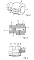
- Figur 2
- eine perspektivische Darstellung des Rotors aus Figur 1 in Alleinstellung;
- Figur 3
- den Rotor aus Figur 2 im Längsschnitt und
- Figur 4
- einen teilweise geschnitten dargestellten Rotor gemäß einer ersten Ausführungsform mit einem eingegossenen Zapfen.
- Figur 5
- eine weitere Ausführungsform eines Rotors mit einem eingegossenen Zapfen.
- Die in Figur 1 dargestellte Vakuumpumpe umfasst ein topfförmiges Gehäuse 1; in dem ein Rotor 2 aus duroplastischem Kunststoff drehbar aufgenommen ist. In einem axialen Abschnitt des Rotors 2 ist ein in Richtung der Drehachse angeordneter Schlitz 3 ausgebildet, der in radialer Richtung durch den Rotor 2 hindurchgeht. Der durchgehende Schlitz 3 dient zur Aufnahme eines Flügels 4, der das Arbeitsvolumen der Vakuumpumpe begrenzt. Die in Figur 1 dargestellte Vakuumpumpe wird, da sie nur einen einzigen Flügel 4 aufweist, auch als Monoflügelzellenpumpe bezeichnet. Die Funktionsweise einer Flügelzellenpumpe wird als bekannt vorausgesetzt und deshalb im Folgenden nicht weiter erläutert.
- Der Rotor 2 hat im Wesentlichen die Gestalt eines Kreiszylinders, der durch den Schlitz 3 in zwei Kreiszylinderhälften unterteilt ist. Die beiden Kreiszylinderhälften sind an einem Ende durch eine Deckscheibe 5 miteinander verbunden, die den Schlitz 3 in axialer Richtung begrenzt. Die Deckscheibe 5 hat die Form einer Kreisscheibe, deren Durchmesser kleiner ist als der Durchmesser des Rotors im Bereich des Schlitzes 3. Die Deckscheibe 5 ist in einem Ge-häusedeckel 6 in einer Ausnehmung 8 aufgenommen. Der Gehäusedeckel 6 verschließt das Gehäuse 1. Die Ausnehmung 8 in dem Gehäusedeckel 6 ist so bemessen, dass zwischen der Deckscheibe 5 und der Ausnehmung 8 sowohl in radialer als auch in axialer Richtung etwas Spiel vorhanden ist.
- In den Figuren 2 und 3 sieht man, dass auf der der Deckscheibe 5 entgegengesetzten Seite des Schlitzes 3 eine Ölzuführbohrung 10 in dem Rotor 2 vorgesehen ist. Ausgehend von der Deckscheibe 5 weist der Rotor 2 zunächst einen Flügelabschnitt 12 auf, der einen deutlich größeren Außendurchmesser aufweist als die Deckscheibe 5. In dem Flügelabschnitt 12 ist der Schlitz 3 zur Aufnahme des Flügels ausgespart. Auf den Flügelabschnitt 12 folgt ein Lagerabschnitt 14, dessen Außendurchmesser deutlich kleiner als der Außendurchmesser des Flügelabschnitts 12 ist, aber etwas größer als der Außendurchmesser der Deckscheibe 5. Der Lagerabschnitt 14 bildet zusammen mit der zugehörigen Gehäusefläche ein Gleitlager. Die in dem Lagerabschnitt 14 angeordnete Bohrung 10 dient dazu, das Lager mit Schmiermittel zu versorgen. In dem freien Ende des Lagerabschnitts 14 ist eine zentrale Ausnehmung 16 für ein Kupplungselement ausgebildet. Das (nicht dargestellte) Kupplungselement dient dazu, die Drehmomentübertragung von einer Antriebswelle auf den Rotor 2 sicherzustellen.
- In Figur 4 ist eine ersten Ausführungsform eines Rotors 22 teilweise geschnitten dargestellt. Der Rotor 22 weist wie der in den Figuren 2 und 3 dargestellte Rotor im Wesentlichen die Gestalt eines Kreiszylinders mit drei Abschnitten auf, die unterschiedliche Außendurchmesser haben. Ein Lagerabschnitt 24 ist an dem antriebswellenseitigen Ende des Rotors 22 ausgebildet. Auf den Lagerabschnitt 24 folgt ein Flügelabschnitt 26, der einen größeren Außendurchmesser als der Lagerabschnitt 24 aufweist. Danach folgt eine Deckscheibe 28, die den gleichen Außendurchmesser, aber eine geringere Dicke wie der Lagerabschnitt 24 aufweist. In die Deckscheibe 28 ist ein Ende 30 eines Zapfens 32 aus Metall eingegossen. Der Zapfen 32 kann an seinem freien Ende 34 als Sechskant ausgebildet sein, um eine formschlüssige Verbindung mit dem Rotor einer weiteren Pumpeneinheit zu ermöglichen.
- In Figur 5 ist eine weitere Ausführungsform eines Rotors mit einem Metallzapfen dargestellt. Der Kunststoffrotor 101 weist einen Außenteil 103 und einen Innenteil 105 auf und kann aus einem Duroplast oder einem Thermoplast, z. B. mittels eines Spritzgießverfahrens, hergestellt sein. Der Innenteil 105 ist im wesentlichen zylinderförmig und weist einen rechteckigen Durchbruch 107 auf, der zur Führung eines Flügels dient. Der Außenteil 103 ist im wesentlichen ebenfalls ein zylinderförmiger Körper, der einen größeren Durchmesser als der Innenteil 105 aufweist, wobei beide Zylinderkörper im Bereich des Schlitzes 107 für den Flügel unterbrochen sind. Die beiden Rotorteile 103 und 105 sind in einem Bodenbereich 109 miteinander verbunden und können zusätzlich durch Rippen 111 miteinander verbunden sein. Der Bodenbereich 109 weist einen zylindrischen Endteil 113 auf, dessen Mantelfläche 115 als erstes Rotorlager innerhalb eines Vakuumpumpengehauses dient. Weiterhin sind im Bodenbereich 109 des Kunststoffrotors 101 Vertiefungen 117, z. B. in rechteckiger Form, angeordnet, welche der Aufnahme von Antriebsmitteln, wie z. B. einer Kupplung, dienen. Auf der dem Bodenbereich 109 entgegengesetzten Seite des Kunststoffrotors ragt der Innenteil 105 mit einem Zylinderteil 119 aus dem Außenteil 103 hervor, wobei die Mantelfläche 121 dieses Zylinderteils 119 ein zweites Lager des Kunststoffrotors in einem hier nicht dargestellten Gehäuse bilden kann. In dem zylindrischen Teil 119 des Kunststoffrotors ist ein metallischer Zapfen 123 eingelassen, der mit formschlüssigen Außenkonturen 125, wie z. B. einer Rändelung, bei dem Spritzgussvorgang als Einlegeteil in der Spritzgussform in den Kunststoffrotor eingegossen werden kann. Selbstverständlich sind auch andere Arten des Formschlusses, wie z. B. ein Sechskant, eine oder mehrere Anflächungen, eine Verzahnung etc. denkbar. Der Metallzapfen 123 hat primär die Funktion eines Dichtzapfens, da er mit seiner zylindrischen Oberfläche 127 gegen einen Radialwellendichtring 129 abdichtet. Durch den Wellendichtring 129 und den Dichtzapfen 123 wird der Durchbruch durch die Pumpengehäusewand 131 abgedichtet, wobei auf der Seite 133 des Pumpengehäuses die Vakuumatmosphäre, d. h. die mit einem Schmieröl versehene Luftatmosphäre, und auf der Seite 135 das Medium einer Kraftstoffförderpumpe, wie z. B. Dieselkraftstoff, anliegt. Erfindungsgemäß ist der Dichtzapfen aus Metall hergestellt, um mit dem Wellendichtring zusammen die Abdichtfunktion zu gewährleisten. Im Rahmen der Erfindung durchgeführte Versuche haben ergeben, daß es nicht möglich ist, den Wellendichtring direkt auf einer Kunststoffoberfläche laufen zu lassen, da sie zu weich ist. Zusätzlich weist der Dichtzapfen eine Verlängerung 137 auf, die als Antriebselement für die Kraftstoffförderpumpe dienen kann. Für die Funktion wesentlich ist, dass der Dichtzapfen nur als Dichtungsfunktionsteil zwischen den beiden Pumpen und als Antriebsfunktionsteil für die Kraftstoffförderpumpe dient und keine Lagerfunktion innerhalb des Pumpengehäuses übernimmt, da die Lagerfunktion durch den Kunststoffrotor selbst mit seinen beiden Lagerflächen 121 und 115 wahrgenommen werden kann und somit eine metallische Welle, Einbauraum und entsprechende Wellenlagerungen sowie Gewicht eingespart werden können. Der Dichtzapfen 123 hat eine glatte und harte Oberfläche, wobei das Metall oberflächlich oder durchgängig gehärtet sein kann, insbesondere im Bereich 127, und dient damit als Lauffläche für den Wellendichtring 129. Mit dieser Dichteinheit wird die Medientrennung zwischen Vakuum und Kraftstoff innerhalb der Tandempumpe gewährleistet. Der Rotor 101 hat ein geringes Gewicht, da er aus Kunststoff besteht, und baut kompakt, da keine separate Lagerung des Dichtzapfens 123 erforderlich ist. Der Dichtzapfen 123 dient zusätzlich als Antrieb 137 für die zweite Pumpeneinheit einer Tandempumpe, wie z. B. einer Kraftstoffförderpumpe.
Claims (18)
- Vakuumpumpe, insbesondere für Bremskraftverstärker-Anlagen in Kraftfahrzeugen, mit einem Gehäuse, in dem ein angetriebener Rotor aus Kunststoff drehbar aufgenommen ist, dadurch gekennzeichnet, dass der Rotor auf der der Antriebsseite gegenüberliegenden Seite einen im Rotor angeordneten Zapfen aus Metall aufweist und der Zapfen (32, 123) keine Lagerstelle im Gehäuse der Vakuumpumpe aufweist.
- Vakuumpumpe nach Anspruch 1, dadurch gekennzeichnet, dass der Rotor aus einem duroplastischen Kunststoff gebildet ist.
- Vakuumpumpe nach Anspruch 1, dadurch gekennzeichnet, dass der Rotor massiv ausgebildet ist.
- Vakuumpumpe nach einem der vorhergehenden Ansprüche, dadurch gekennzeichnet, dass der Rotor im Wesentlichen die Gestalt eines Kreiszylinders aufweist.
- Vakuumpumpe nach einem der vorhergehenden Ansprüche, dadurch gekennzeichnet, dass der Rotor einen in radialer Richtung durchgehenden Schlitz für einen Flügel aufweist.
- Vakuumpumpe nach Anspruch 1, dadurch gekennzeichnet, dass der Rotor an einem Ende mit einer Antriebswelle koppelbar nur an diesem Ende in dem Gehäuse gelagert ist, und an dem anderen Ende mit einer Deckscheibe ausgestattet ist, die einstückig mit dem Rotor ausgebildet ist und den Schlitz in axialer Richtung abschließt.
- Vakuumpumpe nach Anspruch 6, dadurch gekennzeichnet, dass die Deckscheibe mit radialem Spiel in einer Ausnehmung in einem Teil des Gehäuses, insbesondere in einem Gehäusedeckel, zumindest teilweise aufgenommen ist.
- Vakuumpumpe nach Anspruch 7, dadurch gekennzeichnet, dass die Deckscheibe mit axialem Spiel in der Ausnehmung aufgenommen ist.
- Vakuumpumpe nach Anspruch 1, dadurch gekennzeichnet, dass auf der der Antriebswelle abgewandten Seite in den Rotor ein Zapfen eingegossen ist, der zum Antrieb eines weiteren Förderaggregats dient.
- Vakuumpumpe nach Anspruch 1, dadurch gekennzeichnet, dass der Rotor aus einem Kunststoff auf Phenolharz- oder Epoxidharzbasis, insbesondere mit einem Anteil Polytetrafluoräthylen, gebildet ist.
- Vakuumpumpe nach Anspruch 1, dadurch gekennzeichnet, dass der Rotor mit einer Gleitbeschichtung zur Minderung von Reibung und Verschleiß und/oder als Lebensdauerschmierschicht versehen ist, insbesondere aus aushärtbaren, organischen Polymeren mit einer Mindestschichtdicke von 30 ± 10 µm.
- Vakuumpumpe nach Anspruch 1, dadurch gekennzeichnet, dass der Zapfen als Dichtzapfen dient und seine Oberfläche die Lauffläche für einen Wellendichtring darstellt.
- Vakuumpumpe nach Anspruch 1 oder Anspruch 12, dadurch gekennzeichnet, dass der Zapfen als Einlegeteil formschlüssig in den Rotor eingespritzt oder eingegossen ist.
- Vakuumpumpe nach Anspruch 1 oder Anspruch 12 oder Anspruch 13, dadurch gekennzeichnet, dass der Formschluss durch eine Rändelung oder einen Sechskant oder eine oder mehrere Anflächungen oder eine Verzahnung am Zapfen dargestellt ist.
- Vakuumpumpe nach einem der vorhergehenden Ansprüche, dadurch gekennzeichnet, dass der Kunststoffrotor als Rotor für eine Tandempumpe dient, welche eine ölgeschmierte Vakuumpumpe und eine Kraftstoffförderpumpe aufweist.
- Vakuumpumpe nach einem der vorhergehenden Ansprüche, dadurch gekennzeichnet, dass der Wellendichtring eine Medientrennung zwischen dem Vakuum und dem Kraftstoff realisiert/bewirkt/ermöglicht.
- Vakuumpumpe nach einem der vorhergehenden Ansprüche, dadurch gekennzeichnet, dass die Oberfläche des Dichtzapfens glatt und das Metall oberflächlich oder durchgängig gehärtet ist.
- Vakuumpumpe nach einem der vorhergehenden Ansprüche, dadurch gekennzeichnet, dass der Dichtzapfen zusätzlich als Antrieb für die Kraftstoffförderpumpe dient.
Applications Claiming Priority (5)
| Application Number | Priority Date | Filing Date | Title |
|---|---|---|---|
| DE10150801 | 2001-10-15 | ||
| DE10150801 | 2001-10-15 | ||
| DE10230057 | 2002-07-04 | ||
| DE10230057 | 2002-07-04 | ||
| PCT/DE2002/003839 WO2003036094A2 (de) | 2001-10-15 | 2002-10-11 | Vakuumpumpe |
Publications (2)
| Publication Number | Publication Date |
|---|---|
| EP1438510A2 EP1438510A2 (de) | 2004-07-21 |
| EP1438510B1 true EP1438510B1 (de) | 2007-07-18 |
Family
ID=26010377
Family Applications (1)
| Application Number | Title | Priority Date | Filing Date |
|---|---|---|---|
| EP02776804A Expired - Lifetime EP1438510B1 (de) | 2001-10-15 | 2002-10-11 | Vakuumpumpe |
Country Status (7)
| Country | Link |
|---|---|
| EP (1) | EP1438510B1 (de) |
| AT (1) | ATE367530T1 (de) |
| AU (1) | AU2002339361A1 (de) |
| DE (3) | DE10247668B4 (de) |
| FR (2) | FR2830905B1 (de) |
| IT (1) | ITMI20022168A1 (de) |
| WO (1) | WO2003036094A2 (de) |
Families Citing this family (10)
| Publication number | Priority date | Publication date | Assignee | Title |
|---|---|---|---|---|
| GB9402828D0 (en) * | 1994-02-15 | 1994-04-06 | Wabco Automotive Uk | Vacuum pump |
| EP1327778A3 (de) * | 2000-03-15 | 2003-07-23 | Joma-Hydromechanic GmbH | Flügelzellenpumpe |
| FR2869958B1 (fr) * | 2004-05-07 | 2008-08-08 | Peugeot Citroen Automobiles Sa | Pompe a vide a palette(s) perfectionnee |
| DE102004034925B3 (de) * | 2004-07-09 | 2006-02-16 | Joma-Hydromechanic Gmbh | Einflügelvakuumpumpe |
| WO2006047986A1 (de) * | 2004-11-04 | 2006-05-11 | Ixetic Bad Homburg Gmbh | Pumpe mit beschichtetem rotor |
| DE112012002375A5 (de) * | 2011-06-07 | 2014-02-27 | Ixetic Bad Homburg Gmbh | Rotor für eine Flügelzellenpumpe |
| DE102014226347B3 (de) * | 2014-12-18 | 2016-06-23 | Magna Powertrain Bad Homburg GmbH | Vakuumpumpe und Verfahren zum Betrieb der Vakuumpumpe |
| WO2016150505A1 (en) * | 2015-03-25 | 2016-09-29 | Pierburg Pump Technology Gmbh | Vacuum pump |
| DE102015213099B3 (de) * | 2015-07-13 | 2016-08-04 | Joma-Polytec Gmbh | Kunststoffrotor für Vakuumpumpe |
| DE102021114712B3 (de) | 2021-06-08 | 2022-09-01 | Schaeffler Technologies AG & Co. KG | Hydraulikpumpeneinheit mit gerändelter Verbindung eines Stehlagers mit einem Gehäuse |
Family Cites Families (15)
| Publication number | Priority date | Publication date | Assignee | Title |
|---|---|---|---|---|
| DE2727328A1 (de) * | 1977-06-16 | 1978-12-21 | Peter H Haller | Rotierende hydro-aggregate aus thermoplastischen kunststoffen |
| US4838772A (en) * | 1977-12-06 | 1989-06-13 | Gast Manufacturing Corporation | Cartridge rotary vane pump |
| IT1130363B (it) * | 1980-01-29 | 1986-06-11 | Leonardo Beltrame | Compressore a capsulismo con girante perfezionato,utile in particolare per gonfiaggio od alimentazione di avvisatoripneumatici per veicoli |
| DE3122336A1 (de) * | 1980-06-06 | 1982-03-04 | Barmag Barmer Maschinenfabrik Ag, 5630 Remscheid | "einheit aus luftunterdruckpumpe fuer bremskraftverstaerker und kraftstoffoerderpumpe in kraftfahrzeugen" |
| JPS60113085A (ja) * | 1983-11-22 | 1985-06-19 | Matsushita Electric Ind Co Ltd | 冷媒圧縮機 |
| DE3623392C2 (de) * | 1985-07-24 | 1995-04-06 | Barmag Barmer Maschf | Pumpenkombination |
| JPS6291688A (ja) * | 1985-10-17 | 1987-04-27 | Diesel Kiki Co Ltd | 圧縮機のロ−タ |
| DE4130482A1 (de) * | 1991-09-13 | 1993-03-18 | Bayer Ag | Spritzgiessbare formmassen |
| GB9708397D0 (en) * | 1997-04-25 | 1997-06-18 | Boc Group Plc | Improvements in vacuum pumps |
| IT1293672B1 (it) * | 1997-08-01 | 1999-03-08 | Magneti Marelli Spa | Depressore rotativo a palette. |
| DE19819032A1 (de) * | 1998-04-29 | 2000-02-10 | Erich Borgmeier | Verfahren zur Herstellung von sich in Maschinen und Aggregaten drehenden Teilen oder in anderen diese Teile aufnehmenden Öffnungen oder Hohlräumen |
| DE19844904C1 (de) * | 1998-09-30 | 2000-02-17 | Luk Automobiltech Gmbh & Co Kg | Vakuumpumpe |
| DE19901419C2 (de) * | 1999-01-18 | 2002-11-07 | Jose Poch-Parramon | Kunststoffmischung |
| JP4176231B2 (ja) * | 1999-03-23 | 2008-11-05 | 東芝キヤリア株式会社 | 密閉形電動圧縮機 |
| JP2001115959A (ja) * | 1999-10-19 | 2001-04-27 | Matsushita Electric Ind Co Ltd | 圧縮機 |
-
2002
- 2002-10-11 WO PCT/DE2002/003839 patent/WO2003036094A2/de not_active Ceased
- 2002-10-11 FR FR0212664A patent/FR2830905B1/fr not_active Expired - Fee Related
- 2002-10-11 EP EP02776804A patent/EP1438510B1/de not_active Expired - Lifetime
- 2002-10-11 DE DE10247668A patent/DE10247668B4/de not_active Expired - Fee Related
- 2002-10-11 DE DE10294902T patent/DE10294902D2/de not_active Expired - Fee Related
- 2002-10-11 AT AT02776804T patent/ATE367530T1/de not_active IP Right Cessation
- 2002-10-11 DE DE50210520T patent/DE50210520D1/de not_active Expired - Lifetime
- 2002-10-11 AU AU2002339361A patent/AU2002339361A1/en not_active Abandoned
- 2002-10-14 IT IT002168A patent/ITMI20022168A1/it unknown
-
2003
- 2003-03-14 FR FR0303162A patent/FR2845735A1/fr active Pending
Also Published As
| Publication number | Publication date |
|---|---|
| FR2830905B1 (fr) | 2006-02-03 |
| DE50210520D1 (de) | 2007-08-30 |
| WO2003036094A3 (de) | 2003-10-30 |
| ATE367530T1 (de) | 2007-08-15 |
| FR2830905A1 (fr) | 2003-04-18 |
| EP1438510A2 (de) | 2004-07-21 |
| DE10247668B4 (de) | 2013-03-07 |
| WO2003036094A2 (de) | 2003-05-01 |
| DE10294902D2 (de) | 2004-09-16 |
| DE10247668A1 (de) | 2003-04-17 |
| FR2845735A1 (fr) | 2004-04-16 |
| ITMI20022168A1 (it) | 2003-04-16 |
| AU2002339361A1 (en) | 2003-05-06 |
Similar Documents
| Publication | Publication Date | Title |
|---|---|---|
| WO2019166319A1 (de) | Elektrische antriebsvorrichtung, insbesondere für ein kraftfahrzeug oder eine elektrische wasserpumpe | |
| DE10247668B4 (de) | Vakuumpumpe | |
| WO2010130522A1 (de) | Elektrisch angetriebene flüssigkeitspumpe mit einem mehrteiligen rotor und herstellungsverfahren für einen solchen rotor | |
| DE29924585U1 (de) | Vakuumpumpe | |
| DE20301647U1 (de) | Wälzlager, insbesondere für einen Elektromotor | |
| EP3604842B1 (de) | Verfahren zur herstellung einer rotoreinheit | |
| DE102018220007A1 (de) | Seitenkanalverdichter für ein Brennstoffzellensystem zur Förderung und/oder Verdichtung von einem gasförmigen Medium | |
| EP1777417B1 (de) | Turbolader | |
| EP1437518B1 (de) | Lageranordnung | |
| EP2002169B1 (de) | Schmiermittel- oder hydraulikpumpe | |
| DE102018119719A1 (de) | Fluiddynamisches Lagersystem | |
| DE102005032630A1 (de) | Fluiddynamisches Lagersystem | |
| DE102013224416A1 (de) | Axiallager bestehend aus zwei Axiallagerscheiben zur Lagerung einer Läuferwelle eines Abgasturboladers | |
| DE102005032631A1 (de) | Fluiddynamisches Lagersystem | |
| EP1461534B1 (de) | Pumpe | |
| DE102019217959A1 (de) | Exzenterachse mit Lagerhülsen und Verfahren zur Herstellung einer Exzenterachse | |
| WO2013079058A2 (de) | Gehäusebauteil | |
| DE10334003A1 (de) | Pumpe | |
| DE19539035C2 (de) | Rotationsverdrängerkleinpumpe | |
| DE29701391U1 (de) | Radialplungerpumpe | |
| DE3246500C2 (de) | ||
| WO2004083604A1 (de) | Pumpenrotor | |
| DE3015040C2 (de) | Rotationsverdrängerpumpe | |
| EP4636272A1 (de) | Lageranordnung für eine antriebskomponente eines elektrischen antriebs | |
| DE102024107001A1 (de) | Schraubenspindelpumpe mit Druckentlastung |
Legal Events
| Date | Code | Title | Description |
|---|---|---|---|
| PUAI | Public reference made under article 153(3) epc to a published international application that has entered the european phase |
Free format text: ORIGINAL CODE: 0009012 |
|
| 17P | Request for examination filed |
Effective date: 20040517 |
|
| AK | Designated contracting states |
Kind code of ref document: A2 Designated state(s): AT BE BG CH CY CZ DE DK EE ES FI FR GB GR IE IT LI LU MC NL PT SE SK TR |
|
| AX | Request for extension of the european patent |
Extension state: AL LT LV MK RO SI |
|
| RIC1 | Information provided on ipc code assigned before grant |
Ipc: F04C 23/00 20060101ALI20060202BHEP Ipc: F04C 29/00 20060101ALI20060202BHEP Ipc: F04C 18/344 20060101AFI20060202BHEP |
|
| GRAP | Despatch of communication of intention to grant a patent |
Free format text: ORIGINAL CODE: EPIDOSNIGR1 |
|
| GRAS | Grant fee paid |
Free format text: ORIGINAL CODE: EPIDOSNIGR3 |
|
| RAP1 | Party data changed (applicant data changed or rights of an application transferred) |
Owner name: IXETIC HUECKESWAGEN GMBH |
|
| GRAA | (expected) grant |
Free format text: ORIGINAL CODE: 0009210 |
|
| AK | Designated contracting states |
Kind code of ref document: B1 Designated state(s): AT BE BG CH CY CZ DE DK EE ES FI FR GB GR IE IT LI LU MC NL PT SE SK TR |
|
| REG | Reference to a national code |
Ref country code: GB Ref legal event code: FG4D Free format text: NOT ENGLISH |
|
| REG | Reference to a national code |
Ref country code: CH Ref legal event code: EP |
|
| REF | Corresponds to: |
Ref document number: 50210520 Country of ref document: DE Date of ref document: 20070830 Kind code of ref document: P |
|
| REG | Reference to a national code |
Ref country code: IE Ref legal event code: FG4D Free format text: LANGUAGE OF EP DOCUMENT: GERMAN |
|
| ET | Fr: translation filed | ||
| PG25 | Lapsed in a contracting state [announced via postgrant information from national office to epo] |
Ref country code: PT Free format text: LAPSE BECAUSE OF FAILURE TO SUBMIT A TRANSLATION OF THE DESCRIPTION OR TO PAY THE FEE WITHIN THE PRESCRIBED TIME-LIMIT Effective date: 20071218 Ref country code: FI Free format text: LAPSE BECAUSE OF FAILURE TO SUBMIT A TRANSLATION OF THE DESCRIPTION OR TO PAY THE FEE WITHIN THE PRESCRIBED TIME-LIMIT Effective date: 20070718 Ref country code: ES Free format text: LAPSE BECAUSE OF FAILURE TO SUBMIT A TRANSLATION OF THE DESCRIPTION OR TO PAY THE FEE WITHIN THE PRESCRIBED TIME-LIMIT Effective date: 20071029 Ref country code: BG Free format text: LAPSE BECAUSE OF FAILURE TO SUBMIT A TRANSLATION OF THE DESCRIPTION OR TO PAY THE FEE WITHIN THE PRESCRIBED TIME-LIMIT Effective date: 20071018 Ref country code: NL Free format text: LAPSE BECAUSE OF FAILURE TO SUBMIT A TRANSLATION OF THE DESCRIPTION OR TO PAY THE FEE WITHIN THE PRESCRIBED TIME-LIMIT Effective date: 20070718 |
|
| NLV1 | Nl: lapsed or annulled due to failure to fulfill the requirements of art. 29p and 29m of the patents act | ||
| GBV | Gb: ep patent (uk) treated as always having been void in accordance with gb section 77(7)/1977 [no translation filed] |
Effective date: 20070718 |
|
| REG | Reference to a national code |
Ref country code: IE Ref legal event code: FD4D |
|
| BERE | Be: lapsed |
Owner name: IXETIC HUCKESWAGEN G.M.B.H. Effective date: 20071031 |
|
| PG25 | Lapsed in a contracting state [announced via postgrant information from national office to epo] |
Ref country code: GR Free format text: LAPSE BECAUSE OF FAILURE TO SUBMIT A TRANSLATION OF THE DESCRIPTION OR TO PAY THE FEE WITHIN THE PRESCRIBED TIME-LIMIT Effective date: 20071019 Ref country code: DK Free format text: LAPSE BECAUSE OF FAILURE TO SUBMIT A TRANSLATION OF THE DESCRIPTION OR TO PAY THE FEE WITHIN THE PRESCRIBED TIME-LIMIT Effective date: 20070718 |
|
| PLBE | No opposition filed within time limit |
Free format text: ORIGINAL CODE: 0009261 |
|
| STAA | Information on the status of an ep patent application or granted ep patent |
Free format text: STATUS: NO OPPOSITION FILED WITHIN TIME LIMIT |
|
| PG25 | Lapsed in a contracting state [announced via postgrant information from national office to epo] |
Ref country code: CZ Free format text: LAPSE BECAUSE OF FAILURE TO SUBMIT A TRANSLATION OF THE DESCRIPTION OR TO PAY THE FEE WITHIN THE PRESCRIBED TIME-LIMIT Effective date: 20070718 Ref country code: GB Free format text: LAPSE BECAUSE OF FAILURE TO SUBMIT A TRANSLATION OF THE DESCRIPTION OR TO PAY THE FEE WITHIN THE PRESCRIBED TIME-LIMIT Effective date: 20070718 Ref country code: IE Free format text: LAPSE BECAUSE OF FAILURE TO SUBMIT A TRANSLATION OF THE DESCRIPTION OR TO PAY THE FEE WITHIN THE PRESCRIBED TIME-LIMIT Effective date: 20070718 Ref country code: SK Free format text: LAPSE BECAUSE OF FAILURE TO SUBMIT A TRANSLATION OF THE DESCRIPTION OR TO PAY THE FEE WITHIN THE PRESCRIBED TIME-LIMIT Effective date: 20070718 Ref country code: MC Free format text: LAPSE BECAUSE OF NON-PAYMENT OF DUE FEES Effective date: 20071031 |
|
| 26N | No opposition filed |
Effective date: 20080421 |
|
| REG | Reference to a national code |
Ref country code: CH Ref legal event code: PL |
|
| PG25 | Lapsed in a contracting state [announced via postgrant information from national office to epo] |
Ref country code: SE Free format text: LAPSE BECAUSE OF FAILURE TO SUBMIT A TRANSLATION OF THE DESCRIPTION OR TO PAY THE FEE WITHIN THE PRESCRIBED TIME-LIMIT Effective date: 20071018 |
|
| PG25 | Lapsed in a contracting state [announced via postgrant information from national office to epo] |
Ref country code: LI Free format text: LAPSE BECAUSE OF NON-PAYMENT OF DUE FEES Effective date: 20071031 Ref country code: CH Free format text: LAPSE BECAUSE OF NON-PAYMENT OF DUE FEES Effective date: 20071031 |
|
| PG25 | Lapsed in a contracting state [announced via postgrant information from national office to epo] |
Ref country code: BE Free format text: LAPSE BECAUSE OF NON-PAYMENT OF DUE FEES Effective date: 20071031 |
|
| PG25 | Lapsed in a contracting state [announced via postgrant information from national office to epo] |
Ref country code: EE Free format text: LAPSE BECAUSE OF FAILURE TO SUBMIT A TRANSLATION OF THE DESCRIPTION OR TO PAY THE FEE WITHIN THE PRESCRIBED TIME-LIMIT Effective date: 20070718 |
|
| PG25 | Lapsed in a contracting state [announced via postgrant information from national office to epo] |
Ref country code: AT Free format text: LAPSE BECAUSE OF NON-PAYMENT OF DUE FEES Effective date: 20071011 |
|
| PG25 | Lapsed in a contracting state [announced via postgrant information from national office to epo] |
Ref country code: CY Free format text: LAPSE BECAUSE OF FAILURE TO SUBMIT A TRANSLATION OF THE DESCRIPTION OR TO PAY THE FEE WITHIN THE PRESCRIBED TIME-LIMIT Effective date: 20070718 |
|
| PG25 | Lapsed in a contracting state [announced via postgrant information from national office to epo] |
Ref country code: LU Free format text: LAPSE BECAUSE OF NON-PAYMENT OF DUE FEES Effective date: 20071011 |
|
| PG25 | Lapsed in a contracting state [announced via postgrant information from national office to epo] |
Ref country code: TR Free format text: LAPSE BECAUSE OF FAILURE TO SUBMIT A TRANSLATION OF THE DESCRIPTION OR TO PAY THE FEE WITHIN THE PRESCRIBED TIME-LIMIT Effective date: 20070718 |
|
| PGFP | Annual fee paid to national office [announced via postgrant information from national office to epo] |
Ref country code: FR Payment date: 20121113 Year of fee payment: 11 Ref country code: DE Payment date: 20121211 Year of fee payment: 11 |
|
| PGFP | Annual fee paid to national office [announced via postgrant information from national office to epo] |
Ref country code: IT Payment date: 20121024 Year of fee payment: 11 |
|
| REG | Reference to a national code |
Ref country code: FR Ref legal event code: ST Effective date: 20140630 |
|
| REG | Reference to a national code |
Ref country code: DE Ref legal event code: R119 Ref document number: 50210520 Country of ref document: DE Effective date: 20140501 |
|
| PG25 | Lapsed in a contracting state [announced via postgrant information from national office to epo] |
Ref country code: DE Free format text: LAPSE BECAUSE OF NON-PAYMENT OF DUE FEES Effective date: 20140501 Ref country code: FR Free format text: LAPSE BECAUSE OF NON-PAYMENT OF DUE FEES Effective date: 20131031 Ref country code: IT Free format text: LAPSE BECAUSE OF NON-PAYMENT OF DUE FEES Effective date: 20131011 |