EP1437560A1 - Schutzkappe für den Sammelbehälter einer Klimaanlage - Google Patents
Schutzkappe für den Sammelbehälter einer Klimaanlage Download PDFInfo
- Publication number
- EP1437560A1 EP1437560A1 EP03290037A EP03290037A EP1437560A1 EP 1437560 A1 EP1437560 A1 EP 1437560A1 EP 03290037 A EP03290037 A EP 03290037A EP 03290037 A EP03290037 A EP 03290037A EP 1437560 A1 EP1437560 A1 EP 1437560A1
- Authority
- EP
- European Patent Office
- Prior art keywords
- protective cap
- cap according
- sealing
- collecting container
- tube wall
- Prior art date
- Legal status (The legal status is an assumption and is not a legal conclusion. Google has not performed a legal analysis and makes no representation as to the accuracy of the status listed.)
- Granted
Links
Images



Classifications
-
- F—MECHANICAL ENGINEERING; LIGHTING; HEATING; WEAPONS; BLASTING
- F28—HEAT EXCHANGE IN GENERAL
- F28F—DETAILS OF HEAT-EXCHANGE AND HEAT-TRANSFER APPARATUS, OF GENERAL APPLICATION
- F28F9/00—Casings; Header boxes; Auxiliary supports for elements; Auxiliary members within casings
- F28F9/02—Header boxes; End plates
- F28F9/0202—Header boxes having their inner space divided by partitions
-
- F—MECHANICAL ENGINEERING; LIGHTING; HEATING; WEAPONS; BLASTING
- F25—REFRIGERATION OR COOLING; COMBINED HEATING AND REFRIGERATION SYSTEMS; HEAT PUMP SYSTEMS; MANUFACTURE OR STORAGE OF ICE; LIQUEFACTION SOLIDIFICATION OF GASES
- F25B—REFRIGERATION MACHINES, PLANTS OR SYSTEMS; COMBINED HEATING AND REFRIGERATION SYSTEMS; HEAT PUMP SYSTEMS
- F25B39/00—Evaporators; Condensers
- F25B39/04—Condensers
-
- F—MECHANICAL ENGINEERING; LIGHTING; HEATING; WEAPONS; BLASTING
- F25—REFRIGERATION OR COOLING; COMBINED HEATING AND REFRIGERATION SYSTEMS; HEAT PUMP SYSTEMS; MANUFACTURE OR STORAGE OF ICE; LIQUEFACTION SOLIDIFICATION OF GASES
- F25B—REFRIGERATION MACHINES, PLANTS OR SYSTEMS; COMBINED HEATING AND REFRIGERATION SYSTEMS; HEAT PUMP SYSTEMS
- F25B2400/00—Component parts or details not otherwise provided for in this subclass
- F25B2400/16—Receivers
- F25B2400/162—Receivers characterised by the plug or stop
-
- F—MECHANICAL ENGINEERING; LIGHTING; HEATING; WEAPONS; BLASTING
- F28—HEAT EXCHANGE IN GENERAL
- F28F—DETAILS OF HEAT-EXCHANGE AND HEAT-TRANSFER APPARATUS, OF GENERAL APPLICATION
- F28F21/00—Constructions of heat-exchange apparatus characterised by the selection of particular materials
- F28F21/06—Constructions of heat-exchange apparatus characterised by the selection of particular materials of plastics material
- F28F21/067—Details
-
- F—MECHANICAL ENGINEERING; LIGHTING; HEATING; WEAPONS; BLASTING
- F28—HEAT EXCHANGE IN GENERAL
- F28F—DETAILS OF HEAT-EXCHANGE AND HEAT-TRANSFER APPARATUS, OF GENERAL APPLICATION
- F28F2220/00—Closure means, e.g. end caps on header boxes or plugs on conduits
Definitions
- the invention relates to a capacitor with a collecting container and a protective cap in particular for such a condenser with collecting container or collectors.
- the protective cap made of plastic, preferably a polyamide (PA) produced, d. H. a sprayable, relatively strong plastic.
- this plastic cap advantageous to the inside of the container towards a threaded pin or other Befest Trentswagkleit on as a plug-in connection, in a corresponding internal thread or a corresponding receptacle in the sealing plug of the container or in the container itself is screwed or receivable. This will be the Advantage achieved that the necessary sealing force between the cap and Container, d. H. a high sealing effect with simultaneous captivation of the Protective cap are given permanently.
- the cap has a sealing flange with a flat Sealing surface, which pressed against the end face of the collecting container becomes. Due to the pressure of the thread and the rigidity of the Protective cap is achieved a high and lasting sealing effect. Also can a seal may be mounted in such a way that bears with a sealing lip against the Inner wall of the container tube applies.
- the invention is on the outside the cap a profiled handle or a profiled recess for Intervention of a handle provided, a screwing and screwing the Protective cap, for example, allowed by hand.
- the Handle both outside and inside an approximately star-shaped or hexagonal Profile on, so if necessary also inside a corresponding profiled tool can be applied.
- the protective cap with handle and threaded spigot can be easily produced by plastic syringes.
- the Sealing flange a set up outward, preferably wavy edge.
- a sealing plate made of rubber, preferably in corresponding Is buttoned holes of the sealing flange.
- the sealing plate is thus captive connected to the plastic cap. Because the rubber plate softer and more yielding than the plastic of the protective cap, the sealing effect is improved, and small bumps in the surface the end face of the collecting container are compensated by the rubber plate.
- FIG. 1 shows the upper part of a collecting container of a capacitor, such as he was known from the aforementioned DE-A 100 39 260.
- a collecting container 1 consists of an example substantially circular cylindrical tube 2, which in an end face 3 ends.
- the tube 2 is for example by a detachable Sealing plug 4 sealed by a held in an annular groove 6 Circlip 5 is fixed axially.
- the closure plug by loosening the Circlip 5 are removed from the sump 1, z. B. for repair or maintenance reasons.
- the sealing plug 4 has a central projection 7, in which a threaded blind hole 8 is arranged is.
- a protective cap 9 On the end face 3 of the tube 2, a protective cap 9 is placed, the a sealing flange 10, a threaded pin 11 and a handle 12 has.
- the threaded pin 11 is screwed into the threaded blind hole 8, so that the sealing flange 10 with a bias on the end face 3 of the Pipe 2 rests.
- the protective cap 9 is integrally formed and made Plastic injected, preferably made of a polyamide.
- the condenser expediently has a tube / rib block, which is arranged between two headers.
- the tube of the tube / rib block are soldered tightly to the headers and form Flow channels.
- the capacitor are in the Headers arranged partitions, which are serpentine ⁇ strömungsverlauf cause by the tube / rib block. It can several tubes connected in parallel through each passage through the tube / rib block his. Conveniently, the number of tubes varies per pass.
- a collector is arranged with container, through which the condensed refrigerant flows, wherein in the collector
- Fig. 2 shows an embodiment of a protective cap 20 in a first Embodiment.
- a circumferential sealing flange 21 has a flat sealing surface 22, which forms a sealing mating with the end face 3 (FIG.
- the Protective cap 20 has on its upper side a centrally arranged handle 23 and on its underside a threaded pin 24.
- Fig. 2a shows a plan view of the protective cap 20 of FIG. 2 with the circumferential sealing flange 21 and a star-shaped profiled cavity 26.
- the outer contour of the handle 23 is parallel to each other by two extending lines 23a marked; it thus results in a "handy" Extent that facilitates manual screwing and unscrewing. if necessary can in the star-shaped profiled cavity 26 a corresponding profiled tool can be used to tighten the torque - or that Breakaway torque - increase.
- the protective cap shows one reinforced annular portion 21a, which increases the rigidity of the protective cap should increase.
- the ring portion 21 a can advantageously not one have uniform height, which is apparent in Fig. 2.
- the Regions largest increase designated 21 b are the Regions largest increase designated 21 b.
- FIG. 2b shows the protective cap 20 in a section in the plane IIb-IIb in FIG. 2a.
- a conical hollow surface 25 is arranged between the outer, annular sealing surface 22 and the coaxial arranged threaded pin 24 .
- the handle 23 has the profiled cavity 26, the blind hole-like is trained. From the sectional view it becomes clear that the protective cap 20 is injectable as a one-piece plastic part. Between the sealing surface radially outside and the pin is a region 25 can be seen, opposite the sealing surface is withdrawn. This allows the sealing surface at least slightly resilient in the axial direction.
- Fig. 2c shows an isometric view of the protective cap to round off 20 with a view of the sealing flange 21 and the hand or rotary handle 23rd
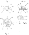
- Fig. 3 shows another embodiment of a protective cap 30 with a raised edge 31 having a wavy contour 32. Like in Previous embodiment according to FIG. 2 also has this protective cap 30 a rotary handle 33 and a coaxially arranged threaded pin 34th on.
- Fig. 3a shows a top view of the protective cap 30 with peripheral edge 31 and circumferentially distributed nubs 37 of the sealing plate 36.
- the rotary handle 33 corresponds in its outer contour 33 a and the cavity 33 b the the previous embodiment of FIG. 2.
- FIG. 3b shows a section through the protective cap 30 in the plane IIIb-IIIb in FIG Fig. 3a.
- the raised edge 31 forms with the sealing flange 35 approximately a right angle, whereby the moment of resistance of the flange 35th is increased.
- an annular sealing plate 36th is connected, which has mushroom-like nubs 37, which in corresponding holes 38 used in the sealing flange 35 or "buttoned" are.
- This is the sealing plate 36 which consists of rubber, captive and sealed with the Protective cap 30 connected.
- the sealing surface with the sealing flange as 2 component element injected.
- Fig. 3c shows an isometric view of the Protective cap 30 with a view of the peripheral edge 31 and the rotary handle 33rd
- FIG. 4 shows a protective cap according to FIG. 1, wherein the sealing surface 50 is designed as a sealing ring 51, which is mounted together with the protective cap.
- the sealing ring has a central opening for receiving the pin.
- FIG. 5 shows a further protective cap according to the invention according to FIG. 1, wherein the sealing ring 60 has a first sealing surface 61 and a second sealing surface 62.
- the sealing surface 61 is formed substantially at the end face and is supported on the end face of the tube of the collecting container.
- the sealing surface 62 is formed substantially cylindrical shell-shaped and is supported on the inner circumferential surface of the tube of the collecting container.
Landscapes
- Engineering & Computer Science (AREA)
- Physics & Mathematics (AREA)
- Thermal Sciences (AREA)
- Mechanical Engineering (AREA)
- General Engineering & Computer Science (AREA)
- Closures For Containers (AREA)
- Pens And Brushes (AREA)
- Air-Conditioning For Vehicles (AREA)
- Transmission Of Braking Force In Braking Systems (AREA)
- Pressure Vessels And Lids Thereof (AREA)
- Buffer Packaging (AREA)
Abstract
Description
- Fig. 1
- eine erfindungsgemäße Schutzkappe auf einem Sammelbehälter,
- Fig. 2
- eine erste Ausführungsform der Schutzkappe,
- Fig. 2a
- eine Draufsicht auf die Schutzkappe gemäß Fig. 2,
- Fig. 2b
- einen Längsschnitt durch die Schutzkappe gemäß Schnittebene IIb-IIb in Fig. 2a,
- Fig. 2c
- eine perspektivische Ansicht der Schutzkappe gemäß Fig. 2,
- Fig. 3
- eine zweite Ausführungsform der Schutzkappe mit zusätzlicher Gummidichtung,
- Fig. 3a
- eine Draufsicht auf die Schutzkappe gemäß Fig. 3,
- Fig. 3b
- einen Längsschnitt durch die Schutzkappe gemäß Schnittebene IIIb-IIIb in Fig. 3a,
- Fig. 3c
- eine perspektivische Ansicht der Schutzkappe gemäß Fig. 3,
- Fig. 4
- eine erfindungsgemäße Schutzkappe auf einem SammelBehälter und
- Fig. 5
- eine erfindungsgemäße Schutzkappe auf einem SammelBehälter.
Die Figur 5 zeigt eine weitere erfindungsgemäße Schutzkappe gemäß Figur 1, wobei der Dichtring 60 eine erste Dichtfläche 61 und eine zweite Dichtfläche 62 aufweist. Die Dichtfläche 61 ist im wesentlichen stirnseitig ausgebildet und stützt sich an der Stirnfläche des Rohres des Sammelbehälters ab. Die Dichtfläche 62 ist im wesentlichen zylindermantelförmig ausgebildet und stützt sich an der Innenmantelfläche des Rohres des Sammelbehälters ab.
Claims (24)
- Schutzkappe zum stirnseitigen Abdichten eines durch einen Verschlussstopfen (4) verschlossenen Sammelbehälters (1) eines Kondensators, wobei der Sammelbehälter (1) eine im wesentlichen über den Verschlussstopfen (4) hinausstehende Rohrwand (2) dadurch gekennzeichnet, dass die Schutzkappe (9, 20, 30) aus einem Kunststoffmaterial hergestellt ist und derart angeordnet ist, daß sie den Sammelbehälter im Bereich des oberhalb der Schutzkappe hinausstehenden Endes der Rohrwand abdichtet.
- Schutzkappe nach Anspruch 1, dadurch gekennzeichnet, daß die Schutzkappe eine im wesentlichen ebene Ringfläche aufweist, die an der stirnseitigen Ringfläche der Rohrwand aufliegt und den Sammelbehälter abdichtet.
- Schutzkappe nach Anspruch 1, dadurch gekennzeichnet, daß die Schutzkappe eine Ringfläche aufweist, die an der umlaufenden Innenmantelfläche der Rohrwand aufliegt und den sammelbehälter abdichtet.
- Schutzkappe nach einem der vorhergehenden Ansprüche, dadurch gekennzeichnet, daß die Schutzkappe einen Haltemittel aufweist, welches mit einem Haltemittel des Verschlußstopfens oder der Rohrwand zusammenwirkt und mit diesem verbunden ist
- Schutzkappe nach einem der vorhergehenden Ansprüche, dadurch gekennzeichnet, daß die Schutzkappe einen Zapfen aufweist, welcher in eine Aufnahme der Verschlußstopfens oder der Rohrwand eingreift.
- Schutzkappe nach einem der vorhergehenden Ansprüche, dadurch gekennzeichnet, daß die Schutzkappe eine Aufnahme aufweist, in welche ein Zapfen des Verschlußstopfens oder der Rohrwand eingreift.
- Schutzkappe nach Anspruch 5 oder 6, dadurch gekennzeichnet, daß der Zapfen ein Gewinde, wie Außengewinde, aufweist, welches in ein Innengewinde der Aufnahme eingreift.
- Schutzkappe nach einem vorhergehenden Anspruch, dadurch gekennzeichnet, dass der Kunststoff ein Polyamid (PA) ist, der gegebenenfalls verstärkt ist durch Faserbeimischung.
- Schutzkappe nach einem vorhergehenden Anspruch, gekennzeichnet durch eine umlaufenden Dichtflansch (10, 21) mit einer ebenen Dichtfläche (22) zur Auflage auf der Stirnfläche (3) der Rohrwand (2).
- Schutzkappe nach einem vorhergehenden Anspruch, gekennzeichnet durch eine umlaufenden Dichtflansch (10, 21) mit einer zylindrischen Dichtfläche (22) zur Auflage auf der Innenmantelfläche der Rohrwand (2).
- Schutzkappe nach einem der vorhergehenden Ansprüche, dadurch gekennzeichnet, daß die Dichtfläche und die Schutzkappe zweiteilig ausgebildet sind.
- Schutzkappe nach Anspruch 11, dadurch gekennzeichnet, daß die Dichtfläche als ringförmiges Element mit der Schutzkappe verbunden ist.
- Schutzkappe nach Anspruch 11, dadurch gekennzeichnet, daß die Dichtfläche als ringförmiges Element mit der Schutzkappe einteilig ausgebildet ist.
- Schutzkappe nach einem vorhergehenden Anspruch, dadurch gekennzeichnet, daß die Dichtfläche aus einem elastischen Material, wie Elastomer, gefertigt ist.
- Schutzkappe nach einem vorhergehenden Anspruch, dadurch gekennzeichnet, dass die Dichtfläche über den Zapfen gegen die Stirnfläche (3) der Rohrwand (2) oder die Innenmantelfläche der Rohrwand verspannt ist.
- Schutzkappe nach einem vorhergehenden Anspruch, dadurch gekennzeichnet, dass zwischen Gewindezapfen (24) und Dichtfläche (22) eine kreisringförmige, konische Hohlfläche (25) angeordnet ist.
- Schutzkappe nach einem der vorhergehenden Ansprüche, gekennzeichnet durch einen zentral angeordneten profilierten Handgriff (23, 33).
- Schutzkappe nach Anspruch 17, dadurch gekennzeichnet, dass der Handgriff (23, 33) hohl ausgebildet ist und ein nach außen offenes Sackloch (26, 33b) mit einem etwa sternförmigen Querschnitt aufweist.
- Schutzkappe nach einem der Ansprüche 1 bis 18, dadurch gekennzeichnet , dass der Dichtflansch (35) einen umlaufenden, aufgestellten Rand (31) aufweist.
- Schutzkappe insbesondere nach Anspruch 19, dadurch gekennzeichnet, dass der Rand (31) eine Oberkante (32) mit einem wellenförmigen Verlauf aufweist.
- Schutzkappe nach einem der vorhergehenden Ansprüche, dadurch gekennzeichnet, dass auf dem Dichtflansch (35) eine mit der Schutzkappe (30) verbundene Dichtplatte (36) aus Gummi angeordnet ist.
- Schutzkappe nach Anspruch 21, dadurch gekennzeichnet, dass die Dichtplatte (36) mittels Noppen (37) in Löcher (38) des Flansches (35) eingeknöpft oder eingespritzt ist.
- Schutzkappe nach einem der vorhergehenden Ansprüche, dadurch gekennzeichnet, dass am Dichtflansch eine umlaufende Dichtlippe angespritzt ist.
- Kondensator mit einem Sammelbehälter mit einer Schutzkappe nach einem der vorhergehenden Ansprüche.
Priority Applications (7)
| Application Number | Priority Date | Filing Date | Title |
|---|---|---|---|
| DE50307004T DE50307004D1 (de) | 2003-01-07 | 2003-01-07 | Kondensator mit Sammelbehälter und Schutzkappe |
| EP03290037A EP1437560B1 (de) | 2003-01-07 | 2003-01-07 | Kondensator mit Sammelbehälter und Schutzkappe |
| AT03290037T ATE359488T1 (de) | 2003-01-07 | 2003-01-07 | Kondensator mit sammelbehälter und schutzkappe |
| JP2004564190A JP4354407B2 (ja) | 2003-01-07 | 2003-11-14 | 凝縮器集合容器内の閉鎖栓用保護キャップ |
| PCT/EP2003/012766 WO2004061376A1 (de) | 2003-01-07 | 2003-11-14 | Schutzkappe für einen verschlussstopfen in einem sammelbehälter eines kondensators |
| AU2003294711A AU2003294711A1 (en) | 2003-01-07 | 2003-11-14 | Protective cap for a sealing stopper on a container for a capacitor |
| US10/541,553 US7334607B2 (en) | 2003-01-07 | 2003-11-14 | Protective cap for a sealing stopper in a collecting vessel of a condenser |
Applications Claiming Priority (1)
| Application Number | Priority Date | Filing Date | Title |
|---|---|---|---|
| EP03290037A EP1437560B1 (de) | 2003-01-07 | 2003-01-07 | Kondensator mit Sammelbehälter und Schutzkappe |
Publications (2)
| Publication Number | Publication Date |
|---|---|
| EP1437560A1 true EP1437560A1 (de) | 2004-07-14 |
| EP1437560B1 EP1437560B1 (de) | 2007-04-11 |
Family
ID=32479962
Family Applications (1)
| Application Number | Title | Priority Date | Filing Date |
|---|---|---|---|
| EP03290037A Expired - Lifetime EP1437560B1 (de) | 2003-01-07 | 2003-01-07 | Kondensator mit Sammelbehälter und Schutzkappe |
Country Status (7)
| Country | Link |
|---|---|
| US (1) | US7334607B2 (de) |
| EP (1) | EP1437560B1 (de) |
| JP (1) | JP4354407B2 (de) |
| AT (1) | ATE359488T1 (de) |
| AU (1) | AU2003294711A1 (de) |
| DE (1) | DE50307004D1 (de) |
| WO (1) | WO2004061376A1 (de) |
Cited By (2)
| Publication number | Priority date | Publication date | Assignee | Title |
|---|---|---|---|---|
| EP1577629A1 (de) * | 2004-03-18 | 2005-09-21 | Behr Lorraine S.A.R.L. | Verschlusselement, Sammelbehälter und Wärmetauscher |
| EP1580501A1 (de) * | 2004-03-24 | 2005-09-28 | DENSO THERMAL SYSTEMS S.p.A. | Filterkartusche für eine Klimaanlage eines Kraftfahrzeuges |
Families Citing this family (33)
| Publication number | Priority date | Publication date | Assignee | Title |
|---|---|---|---|---|
| US8075668B2 (en) | 2005-03-29 | 2011-12-13 | Dresser-Rand Company | Drainage system for compressor separators |
| US20070040375A1 (en) * | 2005-08-17 | 2007-02-22 | Fierst Raymond V | Locating appliance for a non-metallic piping member |
| EP2063978B1 (de) | 2006-09-19 | 2014-07-09 | Dresser-Rand Company | Dichtung für drehabscheidertrommel |
| CA2663531C (en) | 2006-09-21 | 2014-05-20 | William C. Maier | Separator drum and compressor impeller assembly |
| WO2008039733A2 (en) | 2006-09-25 | 2008-04-03 | Dresser-Rand Company | Compressor mounting system |
| BRPI0717087B1 (pt) | 2006-09-25 | 2018-10-16 | Dresser Rand Co | sistema de carretel conector para conectar um primeiro componente e um segundo componente de um sistema de compressão industrial |
| MX2009003175A (es) | 2006-09-25 | 2009-04-03 | Dresser Rand Co | Cubierta de acceso para bobina conectora presurizada. |
| WO2008039446A2 (en) | 2006-09-25 | 2008-04-03 | Dresser-Rand Company | Fluid deflector for fluid separator devices |
| CA2663883C (en) | 2006-09-25 | 2015-02-03 | Kevin M. Majot | Coupling guard system |
| EP2415507A1 (de) | 2006-09-26 | 2012-02-08 | Dresser-Rand Company | Verbesserte statische Flüssigkeitstrennungsvorrichtung |
| WO2009111616A2 (en) | 2008-03-05 | 2009-09-11 | Dresser-Rand Company | Compressor assembly including separator and ejector pump |
| US8079805B2 (en) | 2008-06-25 | 2011-12-20 | Dresser-Rand Company | Rotary separator and shaft coupler for compressors |
| US7922218B2 (en) | 2008-06-25 | 2011-04-12 | Dresser-Rand Company | Shear ring casing coupler device |
| US8062400B2 (en) | 2008-06-25 | 2011-11-22 | Dresser-Rand Company | Dual body drum for rotary separators |
| US8210804B2 (en) | 2009-03-20 | 2012-07-03 | Dresser-Rand Company | Slidable cover for casing access port |
| US8087901B2 (en) | 2009-03-20 | 2012-01-03 | Dresser-Rand Company | Fluid channeling device for back-to-back compressors |
| US8061972B2 (en) * | 2009-03-24 | 2011-11-22 | Dresser-Rand Company | High pressure casing access cover |
| US8414692B2 (en) | 2009-09-15 | 2013-04-09 | Dresser-Rand Company | Density-based compact separator |
| US9095856B2 (en) | 2010-02-10 | 2015-08-04 | Dresser-Rand Company | Separator fluid collector and method |
| WO2012009158A2 (en) | 2010-07-15 | 2012-01-19 | Dresser-Rand Company | Enhanced in-line rotary separator |
| US8663483B2 (en) | 2010-07-15 | 2014-03-04 | Dresser-Rand Company | Radial vane pack for rotary separators |
| US8657935B2 (en) | 2010-07-20 | 2014-02-25 | Dresser-Rand Company | Combination of expansion and cooling to enhance separation |
| US8821362B2 (en) | 2010-07-21 | 2014-09-02 | Dresser-Rand Company | Multiple modular in-line rotary separator bundle |
| JP5936144B2 (ja) | 2010-09-09 | 2016-06-15 | ドレッサー ランド カンパニーDresser−Rand Company | 洗浄可能に制御された排水管 |
| EP2659277B8 (de) | 2010-12-30 | 2018-05-23 | Dresser-Rand Company | Verfahren zur online-erkennung von bodenwiderstandsfehlern in aktiven magnetlagersystemen |
| US8994237B2 (en) | 2010-12-30 | 2015-03-31 | Dresser-Rand Company | Method for on-line detection of liquid and potential for the occurrence of resistance to ground faults in active magnetic bearing systems |
| US9551349B2 (en) | 2011-04-08 | 2017-01-24 | Dresser-Rand Company | Circulating dielectric oil cooling system for canned bearings and canned electronics |
| US8876389B2 (en) | 2011-05-27 | 2014-11-04 | Dresser-Rand Company | Segmented coast-down bearing for magnetic bearing systems |
| US8851756B2 (en) | 2011-06-29 | 2014-10-07 | Dresser-Rand Company | Whirl inhibiting coast-down bearing for magnetic bearing systems |
| WO2014093785A1 (en) * | 2012-12-14 | 2014-06-19 | Flow Dry Technology, Inc. | Access port plug |
| CN110462332B (zh) * | 2017-03-27 | 2020-07-10 | 大金工业株式会社 | 热交换器和空调装置 |
| DE102020215372A1 (de) | 2020-12-04 | 2022-06-09 | Mahle International Gmbh | Verschlussstopfen für einen Sammler eines Kältemittelkreislaufs |
| DE102023130629A1 (de) * | 2023-11-06 | 2025-05-08 | Ifa - Technologies Gmbh | Gelenkaußenteil; Verfahren zur Herstellung eines Gelenkaußenteils |
Citations (10)
| Publication number | Priority date | Publication date | Assignee | Title |
|---|---|---|---|---|
| US4384655A (en) * | 1982-02-12 | 1983-05-24 | Julius Kendall | Pressurized vessel having closure safety means |
| EP0166664A2 (de) * | 1984-05-25 | 1986-01-02 | Application Des Gaz | Schutzkapsel aus Kunststoffmaterial |
| EP0204503A2 (de) * | 1985-05-28 | 1986-12-10 | Nippon Tansan Gas Co., Ltd. | Hochdruckgaspatrone |
| EP0412773A1 (de) * | 1989-08-08 | 1991-02-13 | Nippon Tansan Gas Co., Ltd. | Sauerstoffgasdruckpatrone |
| DE4319293A1 (de) * | 1993-06-10 | 1994-12-15 | Behr Gmbh & Co | Klimaanlage für ein Fahrzeug |
| JP2001033121A (ja) * | 1999-07-16 | 2001-02-09 | Denso Corp | 受液器一体型熱交換器、および受液器 |
| DE10039260A1 (de) | 1999-09-10 | 2001-03-22 | Behr Gmbh & Co | Verschluß für einen Sammelbehälter |
| EP1104879A1 (de) * | 1999-12-01 | 2001-06-06 | Visteon Global Technologies, Inc. | Verflüssiger mit integriertem Sammler-Trockner |
| EP1147930A1 (de) * | 2000-03-24 | 2001-10-24 | Modine Manufacturing Company | Kondensator für die Klimaanlage eines Kraftfahrzeuges |
| GB2366363A (en) * | 2000-08-31 | 2002-03-06 | Llanelli Radiators Ltd | A heat exchanger and tank unit |
Family Cites Families (12)
| Publication number | Priority date | Publication date | Assignee | Title |
|---|---|---|---|---|
| US2366975A (en) * | 1942-10-16 | 1945-01-09 | Louis P Mcchesney | Cleanout plug means |
| US3494504A (en) * | 1968-12-10 | 1970-02-10 | Certain Teed Prod Corp | Pipe closure plug |
| CA944413A (en) * | 1970-10-14 | 1974-03-26 | Gunter H. Wibrow | Hole plug |
| US3765456A (en) * | 1972-04-17 | 1973-10-16 | Anchor Equip Co | Chemical cleaning line connector |
| US4170247A (en) * | 1977-10-25 | 1979-10-09 | John Bates | Polyfluorocarbon condenser plug |
| US4544073A (en) | 1984-01-30 | 1985-10-01 | Bristol-Myers Company | Bottle-overcap combination |
| US5062325A (en) * | 1985-05-10 | 1991-11-05 | Mcgard, Inc. | Pipe plug and centering construction for centering ridged key in mating groove in pipe plug or nut |
| US4693389A (en) * | 1986-01-31 | 1987-09-15 | The Babcock & Wilcox Company | Reactor internals core barrel hole plug |
| US5038830A (en) * | 1986-06-27 | 1991-08-13 | Hydrotreat, Inc. | Pipe and sealing device |
| US5307841A (en) * | 1992-08-10 | 1994-05-03 | Rectorseal Corporation | Test plug for waste pipe |
| DE10066393B4 (de) * | 1999-09-10 | 2018-09-20 | Mahle International Gmbh | Kondensator |
| US6446463B2 (en) * | 2000-03-09 | 2002-09-10 | S.K.G. Italiana S.P.A. | Filter cartridge and condenser |
-
2003
- 2003-01-07 EP EP03290037A patent/EP1437560B1/de not_active Expired - Lifetime
- 2003-01-07 DE DE50307004T patent/DE50307004D1/de not_active Expired - Lifetime
- 2003-01-07 AT AT03290037T patent/ATE359488T1/de active
- 2003-11-14 WO PCT/EP2003/012766 patent/WO2004061376A1/de not_active Ceased
- 2003-11-14 AU AU2003294711A patent/AU2003294711A1/en not_active Abandoned
- 2003-11-14 US US10/541,553 patent/US7334607B2/en not_active Expired - Lifetime
- 2003-11-14 JP JP2004564190A patent/JP4354407B2/ja not_active Expired - Fee Related
Patent Citations (10)
| Publication number | Priority date | Publication date | Assignee | Title |
|---|---|---|---|---|
| US4384655A (en) * | 1982-02-12 | 1983-05-24 | Julius Kendall | Pressurized vessel having closure safety means |
| EP0166664A2 (de) * | 1984-05-25 | 1986-01-02 | Application Des Gaz | Schutzkapsel aus Kunststoffmaterial |
| EP0204503A2 (de) * | 1985-05-28 | 1986-12-10 | Nippon Tansan Gas Co., Ltd. | Hochdruckgaspatrone |
| EP0412773A1 (de) * | 1989-08-08 | 1991-02-13 | Nippon Tansan Gas Co., Ltd. | Sauerstoffgasdruckpatrone |
| DE4319293A1 (de) * | 1993-06-10 | 1994-12-15 | Behr Gmbh & Co | Klimaanlage für ein Fahrzeug |
| JP2001033121A (ja) * | 1999-07-16 | 2001-02-09 | Denso Corp | 受液器一体型熱交換器、および受液器 |
| DE10039260A1 (de) | 1999-09-10 | 2001-03-22 | Behr Gmbh & Co | Verschluß für einen Sammelbehälter |
| EP1104879A1 (de) * | 1999-12-01 | 2001-06-06 | Visteon Global Technologies, Inc. | Verflüssiger mit integriertem Sammler-Trockner |
| EP1147930A1 (de) * | 2000-03-24 | 2001-10-24 | Modine Manufacturing Company | Kondensator für die Klimaanlage eines Kraftfahrzeuges |
| GB2366363A (en) * | 2000-08-31 | 2002-03-06 | Llanelli Radiators Ltd | A heat exchanger and tank unit |
Cited By (2)
| Publication number | Priority date | Publication date | Assignee | Title |
|---|---|---|---|---|
| EP1577629A1 (de) * | 2004-03-18 | 2005-09-21 | Behr Lorraine S.A.R.L. | Verschlusselement, Sammelbehälter und Wärmetauscher |
| EP1580501A1 (de) * | 2004-03-24 | 2005-09-28 | DENSO THERMAL SYSTEMS S.p.A. | Filterkartusche für eine Klimaanlage eines Kraftfahrzeuges |
Also Published As
| Publication number | Publication date |
|---|---|
| AU2003294711A1 (en) | 2004-07-29 |
| US20060254659A1 (en) | 2006-11-16 |
| DE50307004D1 (de) | 2007-05-24 |
| US7334607B2 (en) | 2008-02-26 |
| JP4354407B2 (ja) | 2009-10-28 |
| EP1437560B1 (de) | 2007-04-11 |
| WO2004061376A1 (de) | 2004-07-22 |
| ATE359488T1 (de) | 2007-05-15 |
| JP2006513389A (ja) | 2006-04-20 |
Similar Documents
| Publication | Publication Date | Title |
|---|---|---|
| EP1437560B1 (de) | Kondensator mit Sammelbehälter und Schutzkappe | |
| DE2746517C3 (de) | Spritzeinrichtung | |
| DE102006040888B3 (de) | Verschlusssystem für Behältnisse | |
| EP1447576B1 (de) | Kunststoffmutter zur Aufnahme an einem einen Durchbruch aufweisenden Bauteil | |
| DE3631812A1 (de) | Rohr- oder schlauchverbindungselement | |
| DE69101353T2 (de) | Wasserkasten für einen Hauptwärmetauscher, insbesondere für Kraftfahrzeuge, der einen zweiten Wärmetauscher enthält. | |
| DE2842096A1 (de) | Schlauchkupplung | |
| EP0059877A1 (de) | Kupplung für Druckleitungen | |
| DE1775980A1 (de) | Schlauchkupplung | |
| DE102016224730B3 (de) | Anschlussvorrichtung für eine Fluidleitung und diesbezügliches Montageverfahren | |
| EP1626185A1 (de) | Einstelleinheit zum Einstellen des Abstandes zwischen zwei Bauteilen | |
| DE202004012795U1 (de) | Steckverbindung für Fluid-Leitungen | |
| DE69201143T2 (de) | Rohrschlangenwärmetauscher. | |
| DE102015116301A1 (de) | "Verschlussschraube" | |
| DE3428311A1 (de) | Auslaufelement, insbesondere zur medizinischen verwendung | |
| DE10349527B4 (de) | Schlauch und Schellenfixierung für diesen Schlauch | |
| DE102017205242A1 (de) | Demontagewerkzeug für einen Filtereinsatz eines Flüssigkeitsfilters | |
| DE10106140B4 (de) | Montagewerkzeug für Zentralverschlüsse zum Befestigen von Rädern an einem Kraftfahrzeug | |
| EP1217130A1 (de) | Befestigungsvorrichtung für Armaturenteile | |
| EP0170042B1 (de) | Kupplung | |
| DE9405633U1 (de) | Dichtelement für die Durchführung der Lenksäule durch die Spritzwand eines Kraftfahrzeuges | |
| EP1127661B1 (de) | Befestigungsvorrichtung zur Anbringung eines Stiels an einem Werkzeug | |
| EP1321636A1 (de) | Schraubverschluss für Flüssigkeitsbehälter, insbesondere einer Ölwanne für Kraftfahrzeuge | |
| EP1890069A2 (de) | Steckverbindung | |
| DE4309713A1 (de) | Injektionsvorrichtung für die Holzbehandlung |
Legal Events
| Date | Code | Title | Description |
|---|---|---|---|
| PUAI | Public reference made under article 153(3) epc to a published international application that has entered the european phase |
Free format text: ORIGINAL CODE: 0009012 |
|
| AK | Designated contracting states |
Kind code of ref document: A1 Designated state(s): AT BE BG CH CY CZ DE DK EE ES FI FR GB GR HU IE IT LI LU MC NL PT SE SI SK TR |
|
| AX | Request for extension of the european patent |
Extension state: AL LT LV MK RO |
|
| 17P | Request for examination filed |
Effective date: 20050114 |
|
| AKX | Designation fees paid |
Designated state(s): AT BE BG CH CY CZ DE DK EE ES FI FR GB GR HU IE IT LI LU MC NL PT SE SI SK TR |
|
| RAP1 | Party data changed (applicant data changed or rights of an application transferred) |
Owner name: BEHR FRANCE HAMBACH S.A.R.L. |
|
| GRAP | Despatch of communication of intention to grant a patent |
Free format text: ORIGINAL CODE: EPIDOSNIGR1 |
|
| RTI1 | Title (correction) |
Free format text: CONDENSATOR WITH COLLECTION VESSEL AND PROTECTIVE CAP |
|
| GRAS | Grant fee paid |
Free format text: ORIGINAL CODE: EPIDOSNIGR3 |
|
| GRAA | (expected) grant |
Free format text: ORIGINAL CODE: 0009210 |
|
| AK | Designated contracting states |
Kind code of ref document: B1 Designated state(s): AT BE BG CH CY CZ DE DK EE ES FI FR GB GR HU IE IT LI LU MC NL PT SE SI SK TR |
|
| PG25 | Lapsed in a contracting state [announced via postgrant information from national office to epo] |
Ref country code: SI Free format text: LAPSE BECAUSE OF FAILURE TO SUBMIT A TRANSLATION OF THE DESCRIPTION OR TO PAY THE FEE WITHIN THE PRESCRIBED TIME-LIMIT Effective date: 20070411 Ref country code: FI Free format text: LAPSE BECAUSE OF FAILURE TO SUBMIT A TRANSLATION OF THE DESCRIPTION OR TO PAY THE FEE WITHIN THE PRESCRIBED TIME-LIMIT Effective date: 20070411 |
|
| REG | Reference to a national code |
Ref country code: GB Ref legal event code: FG4D Free format text: NOT ENGLISH |
|
| REG | Reference to a national code |
Ref country code: CH Ref legal event code: EP |
|
| REG | Reference to a national code |
Ref country code: IE Ref legal event code: FG4D Free format text: LANGUAGE OF EP DOCUMENT: GERMAN |
|
| REF | Corresponds to: |
Ref document number: 50307004 Country of ref document: DE Date of ref document: 20070524 Kind code of ref document: P |
|
| PG25 | Lapsed in a contracting state [announced via postgrant information from national office to epo] |
Ref country code: SE Free format text: LAPSE BECAUSE OF FAILURE TO SUBMIT A TRANSLATION OF THE DESCRIPTION OR TO PAY THE FEE WITHIN THE PRESCRIBED TIME-LIMIT Effective date: 20070711 |
|
| PG25 | Lapsed in a contracting state [announced via postgrant information from national office to epo] |
Ref country code: ES Free format text: LAPSE BECAUSE OF FAILURE TO SUBMIT A TRANSLATION OF THE DESCRIPTION OR TO PAY THE FEE WITHIN THE PRESCRIBED TIME-LIMIT Effective date: 20070722 |
|
| PG25 | Lapsed in a contracting state [announced via postgrant information from national office to epo] |
Ref country code: PT Free format text: LAPSE BECAUSE OF FAILURE TO SUBMIT A TRANSLATION OF THE DESCRIPTION OR TO PAY THE FEE WITHIN THE PRESCRIBED TIME-LIMIT Effective date: 20070911 |
|
| NLV1 | Nl: lapsed or annulled due to failure to fulfill the requirements of art. 29p and 29m of the patents act | ||
| ET | Fr: translation filed | ||
| GBV | Gb: ep patent (uk) treated as always having been void in accordance with gb section 77(7)/1977 [no translation filed] |
Effective date: 20070411 |
|
| REG | Reference to a national code |
Ref country code: IE Ref legal event code: FD4D |
|
| PG25 | Lapsed in a contracting state [announced via postgrant information from national office to epo] |
Ref country code: NL Free format text: LAPSE BECAUSE OF FAILURE TO SUBMIT A TRANSLATION OF THE DESCRIPTION OR TO PAY THE FEE WITHIN THE PRESCRIBED TIME-LIMIT Effective date: 20070411 Ref country code: IE Free format text: LAPSE BECAUSE OF FAILURE TO SUBMIT A TRANSLATION OF THE DESCRIPTION OR TO PAY THE FEE WITHIN THE PRESCRIBED TIME-LIMIT Effective date: 20070411 Ref country code: DK Free format text: LAPSE BECAUSE OF FAILURE TO SUBMIT A TRANSLATION OF THE DESCRIPTION OR TO PAY THE FEE WITHIN THE PRESCRIBED TIME-LIMIT Effective date: 20070411 Ref country code: BG Free format text: LAPSE BECAUSE OF FAILURE TO SUBMIT A TRANSLATION OF THE DESCRIPTION OR TO PAY THE FEE WITHIN THE PRESCRIBED TIME-LIMIT Effective date: 20070711 |
|
| PLBE | No opposition filed within time limit |
Free format text: ORIGINAL CODE: 0009261 |
|
| STAA | Information on the status of an ep patent application or granted ep patent |
Free format text: STATUS: NO OPPOSITION FILED WITHIN TIME LIMIT |
|
| PG25 | Lapsed in a contracting state [announced via postgrant information from national office to epo] |
Ref country code: SK Free format text: LAPSE BECAUSE OF FAILURE TO SUBMIT A TRANSLATION OF THE DESCRIPTION OR TO PAY THE FEE WITHIN THE PRESCRIBED TIME-LIMIT Effective date: 20070411 |
|
| 26N | No opposition filed |
Effective date: 20080114 |
|
| PG25 | Lapsed in a contracting state [announced via postgrant information from national office to epo] |
Ref country code: GR Free format text: LAPSE BECAUSE OF FAILURE TO SUBMIT A TRANSLATION OF THE DESCRIPTION OR TO PAY THE FEE WITHIN THE PRESCRIBED TIME-LIMIT Effective date: 20070712 Ref country code: GB Free format text: LAPSE BECAUSE OF FAILURE TO SUBMIT A TRANSLATION OF THE DESCRIPTION OR TO PAY THE FEE WITHIN THE PRESCRIBED TIME-LIMIT Effective date: 20070411 |
|
| BERE | Be: lapsed |
Owner name: BEHR FRANCE HAMBACH S.A.R.L. Effective date: 20080131 |
|
| PG25 | Lapsed in a contracting state [announced via postgrant information from national office to epo] |
Ref country code: MC Free format text: LAPSE BECAUSE OF NON-PAYMENT OF DUE FEES Effective date: 20080131 |
|
| REG | Reference to a national code |
Ref country code: CH Ref legal event code: PL |
|
| PG25 | Lapsed in a contracting state [announced via postgrant information from national office to epo] |
Ref country code: LI Free format text: LAPSE BECAUSE OF NON-PAYMENT OF DUE FEES Effective date: 20080131 Ref country code: CH Free format text: LAPSE BECAUSE OF NON-PAYMENT OF DUE FEES Effective date: 20080131 |
|
| PG25 | Lapsed in a contracting state [announced via postgrant information from national office to epo] |
Ref country code: EE Free format text: LAPSE BECAUSE OF FAILURE TO SUBMIT A TRANSLATION OF THE DESCRIPTION OR TO PAY THE FEE WITHIN THE PRESCRIBED TIME-LIMIT Effective date: 20070411 |
|
| PGFP | Annual fee paid to national office [announced via postgrant information from national office to epo] |
Ref country code: CZ Payment date: 20081229 Year of fee payment: 7 |
|
| PG25 | Lapsed in a contracting state [announced via postgrant information from national office to epo] |
Ref country code: BE Free format text: LAPSE BECAUSE OF NON-PAYMENT OF DUE FEES Effective date: 20080131 |
|
| PG25 | Lapsed in a contracting state [announced via postgrant information from national office to epo] |
Ref country code: CY Free format text: LAPSE BECAUSE OF FAILURE TO SUBMIT A TRANSLATION OF THE DESCRIPTION OR TO PAY THE FEE WITHIN THE PRESCRIBED TIME-LIMIT Effective date: 20070411 |
|
| PGFP | Annual fee paid to national office [announced via postgrant information from national office to epo] |
Ref country code: IT Payment date: 20090127 Year of fee payment: 7 |
|
| PGFP | Annual fee paid to national office [announced via postgrant information from national office to epo] |
Ref country code: FR Payment date: 20100210 Year of fee payment: 8 |
|
| PG25 | Lapsed in a contracting state [announced via postgrant information from national office to epo] |
Ref country code: LU Free format text: LAPSE BECAUSE OF NON-PAYMENT OF DUE FEES Effective date: 20080107 Ref country code: HU Free format text: LAPSE BECAUSE OF FAILURE TO SUBMIT A TRANSLATION OF THE DESCRIPTION OR TO PAY THE FEE WITHIN THE PRESCRIBED TIME-LIMIT Effective date: 20071012 |
|
| PG25 | Lapsed in a contracting state [announced via postgrant information from national office to epo] |
Ref country code: TR Free format text: LAPSE BECAUSE OF FAILURE TO SUBMIT A TRANSLATION OF THE DESCRIPTION OR TO PAY THE FEE WITHIN THE PRESCRIBED TIME-LIMIT Effective date: 20070411 Ref country code: CZ Free format text: LAPSE BECAUSE OF NON-PAYMENT OF DUE FEES Effective date: 20100107 |
|
| PG25 | Lapsed in a contracting state [announced via postgrant information from national office to epo] |
Ref country code: IT Free format text: LAPSE BECAUSE OF NON-PAYMENT OF DUE FEES Effective date: 20100107 |
|
| PGFP | Annual fee paid to national office [announced via postgrant information from national office to epo] |
Ref country code: AT Payment date: 20110121 Year of fee payment: 9 |
|
| REG | Reference to a national code |
Ref country code: FR Ref legal event code: ST Effective date: 20110930 |
|
| PG25 | Lapsed in a contracting state [announced via postgrant information from national office to epo] |
Ref country code: FR Free format text: LAPSE BECAUSE OF NON-PAYMENT OF DUE FEES Effective date: 20110131 |
|
| REG | Reference to a national code |
Ref country code: AT Ref legal event code: MM01 Ref document number: 359488 Country of ref document: AT Kind code of ref document: T Effective date: 20120107 |
|
| PG25 | Lapsed in a contracting state [announced via postgrant information from national office to epo] |
Ref country code: AT Free format text: LAPSE BECAUSE OF NON-PAYMENT OF DUE FEES Effective date: 20120107 |
|
| REG | Reference to a national code |
Ref country code: DE Ref legal event code: R082 Ref document number: 50307004 Country of ref document: DE Representative=s name: GRAUEL, ANDREAS, DIPL.-PHYS. DR. RER. NAT., DE Ref country code: DE Ref legal event code: R081 Ref document number: 50307004 Country of ref document: DE Owner name: MAHLE INTERNATIONAL GMBH, DE Free format text: FORMER OWNER: BEHR FRANCE HAMBACH S.A.R.L., HAMBACH, FR |
|
| PGFP | Annual fee paid to national office [announced via postgrant information from national office to epo] |
Ref country code: DE Payment date: 20200320 Year of fee payment: 18 |
|
| REG | Reference to a national code |
Ref country code: DE Ref legal event code: R119 Ref document number: 50307004 Country of ref document: DE |
|
| PG25 | Lapsed in a contracting state [announced via postgrant information from national office to epo] |
Ref country code: DE Free format text: LAPSE BECAUSE OF NON-PAYMENT OF DUE FEES Effective date: 20210803 |