EP1437497B1 - Dispositif et méthode de régénération d'un filtre à particules applicable à le dispositif de purification des gaz d'échappement d'un moteur à combustion interne - Google Patents
Dispositif et méthode de régénération d'un filtre à particules applicable à le dispositif de purification des gaz d'échappement d'un moteur à combustion interne Download PDFInfo
- Publication number
- EP1437497B1 EP1437497B1 EP04000174A EP04000174A EP1437497B1 EP 1437497 B1 EP1437497 B1 EP 1437497B1 EP 04000174 A EP04000174 A EP 04000174A EP 04000174 A EP04000174 A EP 04000174A EP 1437497 B1 EP1437497 B1 EP 1437497B1
- Authority
- EP
- European Patent Office
- Prior art keywords
- exhaust gas
- particulate
- temperature
- engine
- regeneration
- Prior art date
- Legal status (The legal status is an assumption and is not a legal conclusion. Google has not performed a legal analysis and makes no representation as to the accuracy of the status listed.)
- Expired - Fee Related
Links
Images


Classifications
-
- F—MECHANICAL ENGINEERING; LIGHTING; HEATING; WEAPONS; BLASTING
- F02—COMBUSTION ENGINES; HOT-GAS OR COMBUSTION-PRODUCT ENGINE PLANTS
- F02D—CONTROLLING COMBUSTION ENGINES
- F02D41/00—Electrical control of supply of combustible mixture or its constituents
- F02D41/02—Circuit arrangements for generating control signals
- F02D41/04—Introducing corrections for particular operating conditions
- F02D41/06—Introducing corrections for particular operating conditions for engine starting or warming up
- F02D41/062—Introducing corrections for particular operating conditions for engine starting or warming up for starting
- F02D41/064—Introducing corrections for particular operating conditions for engine starting or warming up for starting at cold start
-
- F—MECHANICAL ENGINEERING; LIGHTING; HEATING; WEAPONS; BLASTING
- F01—MACHINES OR ENGINES IN GENERAL; ENGINE PLANTS IN GENERAL; STEAM ENGINES
- F01N—GAS-FLOW SILENCERS OR EXHAUST APPARATUS FOR MACHINES OR ENGINES IN GENERAL; GAS-FLOW SILENCERS OR EXHAUST APPARATUS FOR INTERNAL COMBUSTION ENGINES
- F01N9/00—Electrical control of exhaust gas treating apparatus
- F01N9/002—Electrical control of exhaust gas treating apparatus of filter regeneration, e.g. detection of clogging
-
- F—MECHANICAL ENGINEERING; LIGHTING; HEATING; WEAPONS; BLASTING
- F02—COMBUSTION ENGINES; HOT-GAS OR COMBUSTION-PRODUCT ENGINE PLANTS
- F02D—CONTROLLING COMBUSTION ENGINES
- F02D41/00—Electrical control of supply of combustible mixture or its constituents
- F02D41/02—Circuit arrangements for generating control signals
- F02D41/021—Introducing corrections for particular conditions exterior to the engine
- F02D41/0235—Introducing corrections for particular conditions exterior to the engine in relation with the state of the exhaust gas treating apparatus
- F02D41/027—Introducing corrections for particular conditions exterior to the engine in relation with the state of the exhaust gas treating apparatus to purge or regenerate the exhaust gas treating apparatus
- F02D41/029—Introducing corrections for particular conditions exterior to the engine in relation with the state of the exhaust gas treating apparatus to purge or regenerate the exhaust gas treating apparatus the exhaust gas treating apparatus being a particulate filter
-
- F—MECHANICAL ENGINEERING; LIGHTING; HEATING; WEAPONS; BLASTING
- F02—COMBUSTION ENGINES; HOT-GAS OR COMBUSTION-PRODUCT ENGINE PLANTS
- F02D—CONTROLLING COMBUSTION ENGINES
- F02D41/00—Electrical control of supply of combustible mixture or its constituents
- F02D41/02—Circuit arrangements for generating control signals
- F02D41/04—Introducing corrections for particular operating conditions
- F02D41/045—Detection of accelerating or decelerating state
-
- F—MECHANICAL ENGINEERING; LIGHTING; HEATING; WEAPONS; BLASTING
- F02—COMBUSTION ENGINES; HOT-GAS OR COMBUSTION-PRODUCT ENGINE PLANTS
- F02D—CONTROLLING COMBUSTION ENGINES
- F02D41/00—Electrical control of supply of combustible mixture or its constituents
- F02D41/02—Circuit arrangements for generating control signals
- F02D41/04—Introducing corrections for particular operating conditions
- F02D41/10—Introducing corrections for particular operating conditions for acceleration
- F02D41/105—Introducing corrections for particular operating conditions for acceleration using asynchronous injection
-
- F—MECHANICAL ENGINEERING; LIGHTING; HEATING; WEAPONS; BLASTING
- F01—MACHINES OR ENGINES IN GENERAL; ENGINE PLANTS IN GENERAL; STEAM ENGINES
- F01N—GAS-FLOW SILENCERS OR EXHAUST APPARATUS FOR MACHINES OR ENGINES IN GENERAL; GAS-FLOW SILENCERS OR EXHAUST APPARATUS FOR INTERNAL COMBUSTION ENGINES
- F01N2430/00—Influencing exhaust purification, e.g. starting of catalytic reaction, filter regeneration, or the like, by controlling engine operating characteristics
-
- F—MECHANICAL ENGINEERING; LIGHTING; HEATING; WEAPONS; BLASTING
- F01—MACHINES OR ENGINES IN GENERAL; ENGINE PLANTS IN GENERAL; STEAM ENGINES
- F01N—GAS-FLOW SILENCERS OR EXHAUST APPARATUS FOR MACHINES OR ENGINES IN GENERAL; GAS-FLOW SILENCERS OR EXHAUST APPARATUS FOR INTERNAL COMBUSTION ENGINES
- F01N2900/00—Details of electrical control or of the monitoring of the exhaust gas treating apparatus
- F01N2900/04—Methods of control or diagnosing
- F01N2900/0421—Methods of control or diagnosing using an increment counter when a predetermined event occurs
-
- F—MECHANICAL ENGINEERING; LIGHTING; HEATING; WEAPONS; BLASTING
- F01—MACHINES OR ENGINES IN GENERAL; ENGINE PLANTS IN GENERAL; STEAM ENGINES
- F01N—GAS-FLOW SILENCERS OR EXHAUST APPARATUS FOR MACHINES OR ENGINES IN GENERAL; GAS-FLOW SILENCERS OR EXHAUST APPARATUS FOR INTERNAL COMBUSTION ENGINES
- F01N2900/00—Details of electrical control or of the monitoring of the exhaust gas treating apparatus
- F01N2900/04—Methods of control or diagnosing
- F01N2900/0422—Methods of control or diagnosing measuring the elapsed time
-
- F—MECHANICAL ENGINEERING; LIGHTING; HEATING; WEAPONS; BLASTING
- F01—MACHINES OR ENGINES IN GENERAL; ENGINE PLANTS IN GENERAL; STEAM ENGINES
- F01N—GAS-FLOW SILENCERS OR EXHAUST APPARATUS FOR MACHINES OR ENGINES IN GENERAL; GAS-FLOW SILENCERS OR EXHAUST APPARATUS FOR INTERNAL COMBUSTION ENGINES
- F01N3/00—Exhaust or silencing apparatus having means for purifying, rendering innocuous, or otherwise treating exhaust
- F01N3/02—Exhaust or silencing apparatus having means for purifying, rendering innocuous, or otherwise treating exhaust for cooling, or for removing solid constituents of, exhaust
- F01N3/021—Exhaust or silencing apparatus having means for purifying, rendering innocuous, or otherwise treating exhaust for cooling, or for removing solid constituents of, exhaust by means of filters
- F01N3/023—Exhaust or silencing apparatus having means for purifying, rendering innocuous, or otherwise treating exhaust for cooling, or for removing solid constituents of, exhaust by means of filters using means for regenerating the filters, e.g. by burning trapped particles
-
- F—MECHANICAL ENGINEERING; LIGHTING; HEATING; WEAPONS; BLASTING
- F02—COMBUSTION ENGINES; HOT-GAS OR COMBUSTION-PRODUCT ENGINE PLANTS
- F02B—INTERNAL-COMBUSTION PISTON ENGINES; COMBUSTION ENGINES IN GENERAL
- F02B37/00—Engines characterised by provision of pumps driven at least for part of the time by exhaust
-
- F—MECHANICAL ENGINEERING; LIGHTING; HEATING; WEAPONS; BLASTING
- F02—COMBUSTION ENGINES; HOT-GAS OR COMBUSTION-PRODUCT ENGINE PLANTS
- F02D—CONTROLLING COMBUSTION ENGINES
- F02D41/00—Electrical control of supply of combustible mixture or its constituents
- F02D41/20—Output circuits, e.g. for controlling currents in command coils
- F02D2041/202—Output circuits, e.g. for controlling currents in command coils characterised by the control of the circuit
- F02D2041/2051—Output circuits, e.g. for controlling currents in command coils characterised by the control of the circuit using voltage control
-
- F—MECHANICAL ENGINEERING; LIGHTING; HEATING; WEAPONS; BLASTING
- F02—COMBUSTION ENGINES; HOT-GAS OR COMBUSTION-PRODUCT ENGINE PLANTS
- F02D—CONTROLLING COMBUSTION ENGINES
- F02D41/00—Electrical control of supply of combustible mixture or its constituents
- F02D41/22—Safety or indicating devices for abnormal conditions
- F02D2041/228—Warning displays
-
- F—MECHANICAL ENGINEERING; LIGHTING; HEATING; WEAPONS; BLASTING
- F02—COMBUSTION ENGINES; HOT-GAS OR COMBUSTION-PRODUCT ENGINE PLANTS
- F02D—CONTROLLING COMBUSTION ENGINES
- F02D2200/00—Input parameters for engine control
- F02D2200/02—Input parameters for engine control the parameters being related to the engine
- F02D2200/04—Engine intake system parameters
- F02D2200/0406—Intake manifold pressure
-
- F—MECHANICAL ENGINEERING; LIGHTING; HEATING; WEAPONS; BLASTING
- F02—COMBUSTION ENGINES; HOT-GAS OR COMBUSTION-PRODUCT ENGINE PLANTS
- F02D—CONTROLLING COMBUSTION ENGINES
- F02D2200/00—Input parameters for engine control
- F02D2200/02—Input parameters for engine control the parameters being related to the engine
- F02D2200/04—Engine intake system parameters
- F02D2200/0414—Air temperature
-
- F—MECHANICAL ENGINEERING; LIGHTING; HEATING; WEAPONS; BLASTING
- F02—COMBUSTION ENGINES; HOT-GAS OR COMBUSTION-PRODUCT ENGINE PLANTS
- F02D—CONTROLLING COMBUSTION ENGINES
- F02D2200/00—Input parameters for engine control
- F02D2200/50—Input parameters for engine control said parameters being related to the vehicle or its components
- F02D2200/503—Battery correction, i.e. corrections as a function of the state of the battery, its output or its type
-
- F—MECHANICAL ENGINEERING; LIGHTING; HEATING; WEAPONS; BLASTING
- F02—COMBUSTION ENGINES; HOT-GAS OR COMBUSTION-PRODUCT ENGINE PLANTS
- F02M—SUPPLYING COMBUSTION ENGINES IN GENERAL WITH COMBUSTIBLE MIXTURES OR CONSTITUENTS THEREOF
- F02M26/00—Engine-pertinent apparatus for adding exhaust gases to combustion-air, main fuel or fuel-air mixture, e.g. by exhaust gas recirculation [EGR] systems
- F02M26/02—EGR systems specially adapted for supercharged engines
- F02M26/04—EGR systems specially adapted for supercharged engines with a single turbocharger
- F02M26/05—High pressure loops, i.e. wherein recirculated exhaust gas is taken out from the exhaust system upstream of the turbine and reintroduced into the intake system downstream of the compressor
-
- Y—GENERAL TAGGING OF NEW TECHNOLOGICAL DEVELOPMENTS; GENERAL TAGGING OF CROSS-SECTIONAL TECHNOLOGIES SPANNING OVER SEVERAL SECTIONS OF THE IPC; TECHNICAL SUBJECTS COVERED BY FORMER USPC CROSS-REFERENCE ART COLLECTIONS [XRACs] AND DIGESTS
- Y02—TECHNOLOGIES OR APPLICATIONS FOR MITIGATION OR ADAPTATION AGAINST CLIMATE CHANGE
- Y02T—CLIMATE CHANGE MITIGATION TECHNOLOGIES RELATED TO TRANSPORTATION
- Y02T10/00—Road transport of goods or passengers
- Y02T10/10—Internal combustion engine [ICE] based vehicles
- Y02T10/40—Engine management systems
Definitions
- the present invention relates to a regeneration apparatus and method for a particulate filter used for a post process of an exhaust gas of mainly, a Diesel engine, and an exhaust gas purifying device using the regeneration apparatus and method described above.
- a Diesel particulate filter is a particulate trap (or collection) device constituted by molding a ceramic to a honeycomb-like monolithic and, generally, is used to remove a particulate matter (hereinafter, referred to simply as a particulate) exhausted from the Diesel engine.
- a particulate a particulate matter exhausted from the Diesel engine.
- the particulate is progressively accumulated as the time has passed. If the accumulated quantity of the particulate is in excess of an allowance quantity, a filter clog occurs and exhaust (gas) pressure is raised so as to give an ill influence on a driveability. It is, therefore, necessary to remove the accumulated particulate at a regular time interval from the exhaust gas so as to prevent the filter clog from occurring.
- a Japanese Patent Application First Publication No. 2000-179326 published on June 27, 2000 exemplifies a previously proposed regeneration method for a Diesel particulate filter in which the particulate is combusted and removed and by operating an engine control device such as injectors so that a temperature of the exhaust gas is raised up to a temperature value higher than that in an ordinary time and the particulate accumulated is heated up to a temperature equal to or higher than a combustion temperature.
- the exhaust gas temperature is raised from a time at which it is determined to be a time for the Diesel particulate filter to be regenerated to a time at which the particulate has combusted and its accumulation quantity has sufficiently been decreased so that it is expected that the Diesel particulate filter is deemed to have been regenerated.
- a target temperature of the exhaust gas to be reached to during this time period is set to a temperature such as 600°C as high as a temperature required for an active combustion of the particulate.
- a method to raise the temperature of the exhaust gas to such a target temperature as described above is that injectors as the engine control device are operated on the Diesel engine in which a fuel injection is distributed a plurality of number of times and an injection timing of a post injection to be carried out after a main injection is retarded than that in the ordinary time.
- the objective is solved according to the independent claim 1.
- Fig. 1 is a schematic block diagram of a Diesel engine to which a particulate filter regeneration apparatus in a first preferred embodiment according to the present invention is applicable;
- Fig. 2 is an operational flowchart representing a regeneration timing determination and a regeneration mode control routine in the first embodiment shown in Fig. 1;
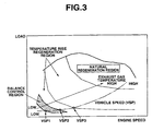
- Fig. 3 is a characteristic graph representing a particulate processing in accordance with an engine driving region
- Fig. 4 is an operational flowchart of a device controlled variable increment/decrement value setting routine
- Fig. 5 is a flowchart representing a device controlled variable increment/decrement value setting routine
- Fig. 6 is a characteristic graph representing a relationship between a particulate combustion speed ⁇ PM and a vehicle speed VSP;
- Fig. 7 is an operational flowchart representing a regeneration mode control routine in a second preferred embodiment according to the present invention.
- Fig. 1 shows a schematic configuration view of a direct injection Diesel engine 1 (hereinafter, also referred simply to as an engine) to which a particulate filter regeneration apparatus in a first preferred embodiment according to the present invention is applicable.
- An air cleaner (not shown) is attached onto an air introduction portion of an intake air passage 2 and (powdered) dust in the intake air is eliminated by means of the air cleaner.
- a compressor portion 3a of a variable nozzle turbo charger (hereinafter, a turbo charger) is attached on a downstream side of the air cleaner. The intake air passed through the air cleaner is compressed and supplied to compressor portion 3a.
- An intercooler 4 is disposed at a downstream side of compressor portion 3a and the intake air pressurized and supplied from compressor portion 3a is cooled by means of this intercooler 4. Furthermore, a throttle valve 6 is disposed at just an upstream side of surge tank 5 and the cooled intake air is passed through a throttle valve 6 and streamed into surge tank 5 and distributed into each cylinder via an intake manifold.
- Injectors 7 are fixed onto a cylinder head of an engine main body so as to be exposed to an approximately center of an upper part of a combustion chamber for each cylinder.
- a fuel system of engine 1 is constituted so as to include a common rail 8.
- the fuel pressurized by means of a fuel pump (not shown) is distributed into each injector via a common rail 8.
- Injectors 7 are activated in response to a fuel injection control signal from an electronic control unit (hereinafter, referred to as an ECU) 21.
- ECU electronice control unit
- a pilot injection to decrease a developed particulate and a post injection to raise a temperature of the exhaust gas during a regeneration of Diesel particulate filter 12 as will be described later are carried out by means of injector 7.
- the pilot injection is carried out by advancing its injection timing angle with respect to the main injection and the post injection is carried out by retarding the timing angle with respect to the main injection.
- a turbine portion 3b of a turbo charger 3 is disposed on a downstream side of a manifold in an exhaust passage 9 and a vane angle of a movable vane of turbo charger 3 is controlled in accordance with the driving condition in response to a supercharged pressure control signal from ECU 21.
- a Diesel particulate filter 12 is disposed as the particulate filter to perform a post processing of the exhaust gas. The particulate is removed from the exhaust gas when the particulate in the exhaust gas passes through Diesel particulate filter (DPF) 12.
- DPF Diesel particulate filter
- an EGR tube 10 is connected for an exhaust recirculation (hereinafter, referred to as an EGR) between exhaust passage 9 and intake air passage 2 (hereinafter, a surge tank 5).
- An EGR control valve 11 is interposed in EGR tube 10. EGR control valve 11 is operated by means of EGR control signal from ECU 21 so that an appropriate quantity of exhaust gas in accordance with the opening angle is circulated into intake air passage 2.
- the exhaust gas purifying device of engine 1 includes a Diesel particulate filter 12 and ECU 21 constituting its regeneration apparatus and sensors
- Signals to be inputted to ECU (Electronic Control Unit) 21 to regenerate Diesel particulate filter 12 includes sensor signals from sensors 31 and 32 to detect exhaust gas temperature Texhin and Texhout at inlet and outlet portions of Diesel particulate filter 12, respectively, from a sensor 33 to detect a pressure difference ⁇ Pdpf between front and rear portions of Diesel particulate filter 12 (forward-and-rearward pressure difference) of Diesel particulate filter 12, from an airflow meter 34, from a crank angle sensor 35, from an accelerator opening angle sensor 36, and from a vehicle speed sensor 37.
- ECU 21 determines whether it is a time for Diesel particulate filter 12 to be regenerated with reference to the flowchart of Fig. 2. Only if ECU 21 determines that it is the time for Diesel particulate filter 12 to be regenerated, the routine advances a step S5. At step S5, ECU 21 performs a control to combust the accumulated particulate. In details, ECU 21 determines whether a regeneration timing determination flag F is zero or not. If ECU 21 determines that this flag ⁇ 0 (No), the routine jumps to step S5.
- Regeneration time determination flag F is set to " 0 " during a start of engine 1. If Diesel particulate filter 12 is regenerated, flag F is set to " 1 " during the regeneration process.
- ECU 21 reads filter forward-and-rearward difference pressure ⁇ Pdpf and exhaust gas flow quantity Qexh.
- a particulate accumulated quantity PM is estimated which is a quantity of the particulate accumulated in Diesel particulate filter 12 from ⁇ Pdpf and Qexh.
- the estimation of a particulate material (matter) PM is made with respect to a map to which PM is allocated in accordance with ⁇ Pdpf and Qexh.
- Qexh can be calculated on the basis of intake air flow quantity Qa detected by means of airflow meter 34.
- ECU 21 determines whether particulate accumulation quantity PM has reached to a prescribed quantity PM1. If particulate accumulation quantity PM has reached to prescribed quantity PM1 at step S3, the routine goes to a step S4. If No (PM does not reach to PM1) at step S3, this routine of Fig. 2 is returned. PM1 indicates a preset upper limit of a particulate allowance accumulation quantity of Diesel Particulate filter 12. Hence, at a time when PM has been reached to PM1, this time is a timing at which Diesel particulate filter 12 should be regenerated. At step S4, regeneration timing determination flag F is set to " 1 ".
- a temperature of the exhaust gas is raised in the following way in order to combust the accumulated particulate in Diesel particulate filter 12.
- the raising of the temperature is carried out to set device controlled variable increment/decrement value dCONT for a predetermined engine control device (hereinafter, referred to as a regeneration time controlled device (step S5).
- dCONT is set in accordance with a flowchart of Fig. 4 as an increment/decrement value of a device controlled variable basic value CONT set for an ordinary engine control.
- injectors 7, turbo charger 3, EGR control valve 11, and intake air throttle valve 6 are included as regeneration mode controlled devices.
- any one or more of the main injection timing, post injection timing, and a post injection quantity, the vane angle of turbo charger 3, an opening angle of EGR control valve 11, and an opening angle of intake throttle valve 6 are adjusted.
- device controlled variable dCONT and its control contents in a case where the temperature of the exhaust gas is raised are described with reference to TABLE 1.
- the driving region of engine 1 is divided into a plurality of regions in accordance with an equivalent exhaust gas (equi-exhaust gas) temperature line (balance control region, temperature rise regeneration region, and a natural regeneration region).
- a practical driving region of engine 1 in accordance with a vehicular velocity (vehicle speed) VSP is as shown in a dot-and-dot-and-dash line (phantom line) of Fig. 3.
- the exhaust gas has a tendency that, as the vehicle speed becomes high, namely, as the driving state falls within a high revolution and a high load region, the temperature thereof becomes high.
- the regeneration temperature for example, 600°C
- the exhaust gas is raised to 400°C through 450°C so as combust the particulate whose quantity is approximately equal to a quantity of the particulate which flows into particulate filter 12 although Diesel particulate 12 cannot be regenerated.
- ECU 21 reads vehicle speed VSP.
- ECU 21 determines whether read vehicle speed VSP is higher than a first prescribed vehicle speed VSP1 (for example, 30 Km/h). If vehicle VSP is higher than first prescribed vehicle speed VSP1 (Yes), the routine goes to a step S13. If vehicle speed VSP is equal to or lower than VSP1 (No) at step S12, the routine goes to a step S14.
- VSP is higher than a second prescribed vehicle speed VSP2 (for example, 50 Km/h) which is set at a higher than VSP1.
- step S15 If vehicle speed VSP is higher than second prescribed vehicle speed VSP2, the routine goes to a step S15. If vehicle speed is equal to or lower than second prescribed vehicle speed VSP2, the routine goes to a step S16.
- step S14 ECU 21 determines if engine 1 falls in an idling state. If engine 1 falls in the idling state (Yes S14), the routine goes to a step S16. If ECU 21 determines that engine 1 does not fall in the idling state (No) at step S14, the routine goes to a step S17. At step S14, the routine may go to a step S16 only if a time duration during which the determination that the engine is in the idling state is continued for a predetermined time.
- a temperature rise regeneration (mode) increment/decrement value dCONTa is set as device controlled variable increment/decrement value dCONT.
- balance control region increment/decrement value dCONTb is set as device controlled variable increment/decrement value dCONT.
- 0 is set to device controlled variable increment/decrement value dCONT (dCONTb nor dCONTa).
- Temperature rise regeneration (mode) increment/decrement value dCONTa and balance control region device controlled variable increment/decrement value dCONTb are searched from a map to which these increment/decrement values are allocated in accordance with the engine driving state (for example, fuel injection quantity Tp and engine speed Ne (revolution speed).
- the engine driving state for example, fuel injection quantity Tp and engine speed Ne (revolution speed).
- device regeneration mode controlled device dCONTa and dCONTb are set (in the case of a single device and in the case of a plurality of devices) is different according to the engine driving state.
- dCONTa is set to actively combust the particulate and set so as to obtain (for example, 600°C) an exhaust gas temperature at which the particulate is actively combusted and at which Diesel particulate filter 12 can be regenerated.
- dCONTb is set with respect to the regeneration timing controlled device in accordance with at least one regeneration mode controlled device so as to obtain, for example, 450°C as an exhaust gas temperature at which the particulate whose quantity is approximately the same as a quantity of the particulate which flows into Diesel particulate filter 12 can be combusted.
- These values dCONTa and dCONTb are set for at least one or a plurality of regeneration mode controlled devices in accordance with the driving condition.
- dCONTb is distinguishably set at step S16 of Fig. 4 in a case where engine 1 falls in an idling state and vehicle speed VSP falls in a range from VSP1 to VSP2. That is to say, in a case where intake air throttle valve 6 is adopted as the regeneration mode controlled device, these values are set to mutually different values (the opening angles of intake air throttle valve 6 are set differently).
- ECU 21 determines, in accordance with a flowchart of Fig. 5, that the regeneration has been completed.
- ECU 21 reads an exhaust gas flow quantity Qexh and a temperature of Diesel particulate filter 12 (hereinafter, referred also to as a filter temperature) Tdpf.
- Particulate combustion temperature velocity ⁇ PM (a quantity corresponding to the particulate combustion per unit time from these Qexh and Tdpf. The estimation of ⁇ PM is allocated in accordance with Qexh and Tdpf.
- ECU 21 determines whether rPM is subtracted by a prescribed value R1. If subtracted into R1 at step S23, the routine goes to a step S24. If not subtracted into R1 at step S23, the present routine is ended.
- Fig. 6 representing a relationship between particulate combustion speed ⁇ PM and vehicle speed VSP.
- the particulate exhausted from engine 1 is continuously accumulated into Diesel particulate filter 12.
- Particulate accumulation quantity PM estimated from Filter forward-and-rearward difference pressure ⁇ Pdpf and exhaust gas flow quantity Qexh has reached to the prescribed quantity PM1.
- ECU 21 determines that it is the time to regenerate Diesel particulate filter 12, ECU 21 sets device controlled quantity increment/decrement value dCONT (dCONTa or dCONTb) to raise the temperature of the exhaust gas in accordance with the driving state of engine 1 at that time.
- ECU 21 sets balance control region increment/decrement value dCONTb as dCONT to raise the temperature of exhaust gas to 450°C.
- particulate combustion speed ⁇ PM becomes substantially equal to the quantity of particulate which flows into Diesel particulate filter 12 within a unit of time.
- ECU 21 sets temperature rise regeneration mode increment/decrement value dCONTa as dCONT.
- the temperature of the exhaust gas is raised to 600°C.
- temperature of the exhaust gas may be raised to a plurality of target temperatures in a stepwise manner. That is to say, in a region A (refer to Fig. 6) in which the vehicular velocity (VSP) falls in a region A in which the vehicular velocity VSP is relatively low speed region of 50 Km/h through 60 Km/h, the exhaust gas temperature is raised to a single target temperature (for example, 570°C). On the other hand, in a region B (refer to Fig.
- the temperature of the exhaust gas is, at first, raised up to a relatively low target temperature (for example, 570°C). Thereafter, when the particulate is combusted and the regeneration is advanced to some degree. At this time, the temperature of exhaust gas is raised up to a higher target temperature (for example, 640°C) than the above relatively low target temperature. It is noted that, when engine 1 falls in the natural regeneration region, the particulate is combusted by means of the heating that the exhaust gas naturally has even if the control to raise the temperature of exhaust gas is not carried out and its accumulation quantity can be decreased.
- a relatively low target temperature for example, 570°C
- steps S2 and S3 in the flowchart of Fig. 2 correspond to regeneration timing determination means (section)
- steps S5 and S6 in the same flowchart correspond to regeneration timing (or mode) controlling section (means)
- step S15 of the flowchart shown in Fig. 4 corresponds to first exhaust gas temperature raising section (means)
- step S16 of the same flowchart corresponds to second exhaust gas temperature raising section (means).
- a temperature raise of the exhaust gas to the target temperature in this embodiment, 450°C
- a retardation quantity the retardation angle is small
- step S16 of the flowchart of Fig. 4 may be replaced with the whole flowchart shown in Fig. 7, a difference between the target temperature and actual exhaust gas temperature is calculated so that such a feedback control that the exhaust gas temperature is made coincident with the target temperature may be carried out.
- ECU 21 sets a balance control region increment/decrement value dCONTb during the balance control mode increment/decrement value dCONTb.
- ECU 21 reads temperature Texhin of the exhaust gas at the filter inlet portion.
- ECU 21 sets a feedback correction coefficient Kfb in accordance with a difference between target temperature tTexh (for example, 450°C described above) and Texhin. Kfb is set to " 1 " when tTexh is made coincident with Texin.
- Kfb is set as a larger value (provided that it is larger than zero).
- the whole flowchart of Fig. 7 constitutes second exhaust gas temperature raising means (section).
- a feedback function as described above is provided with the regeneration apparatus of Diesel particulate filter 12.
- the exhaust gas can accurately be raised to the target temperature.
- the temperature of the exhaust gas can be feedback controlled.
- ECU 21 includes a microcomputer having a CPU (Central Processing Unit), a ROM (Read Only Memory), a RAM (Random Access Memory), an Input port, an Output Port, common bus, and so forth and a longitudinal axis of Fig. 3 denotes an engine load and a lateral axis of Fig. 3 denotes the engine speed.
Claims (19)
- Appareil de régénération d'un filtre à particules (12) collectant une matière particulaire (MP) dans des gaz d'échappement d'un moteur à combustion interne (1), l'appareil de régénération comprenant:une section de détermination de cadencement de régénération (21, S1 à S4) déterminant un cadencement auquel une matière particulaire accumulée est brûlée pour régénérer le filtre à particules; etune section de commande de mode de régénération (21, S5, S6) effectuant une commande d'une combustion des matières particulaires, la section de commande de mode de régénération comprenant une première section d'élévation de température des gaz d'échappement (21, 25) élevant une température des gaz d'échappement du moteur à une première température cible réglée à une température égale ou supérieure à un premier critère de température auquel la matière particulaire est brûlée pour régénérer le filtre à particules lorsque le moteur tombe dans une première région de conduite; et une seconde section d'élévation de température des gaz d'échappement (21, S16) élevant la température des gaz d'échappement du moteur à une seconde température cible réglée à une température inférieure au critère de température lorsque le moteur tombe dans une seconde région de conduite différente de la première région de conduite.
- Appareil de régénération selon la revendication 1, dans lequel la seconde température cible (tTexh) est une température des gaz d'échappement du moteur pour brûler la matière particulaire (MP) dont la quantité est approximativement égale à une quantité des matières particulaires qui s'écoulent dans le filtre à particules.
- Appareil de régénération selon la revendication 1 ou 2, dans lequel la première section d'élévation de température des gaz d'échappement (21, S15) élève la température des gaz d'échappement à la première température cible réglée à une température pour brûler les matières particulaires afin de diminuer une quantité d'accumulation des matières particulaires dans le filtre à particules lorsque le moteur tombe dans la première région de conduite.
- Appareil de régénération selon au moins l'une des revendications 1 à 3, dans lequel la seconde région de conduite est une région de conduite située au niveau d'un côté de vitesse de véhicule inférieur à la première région de conduite.
- Appareil de régénération selon au moins l'une des revendications 1 à 4, dans lequel la seconde section d'élévation de température des gaz d'échappement comprend:une section de détection (31) détectant une température de gaz d'échappement (Texhin); etune section de commande de température des gaz d'échappement (21) commandant la température des gaz d'échappement sur la base de la température des gaz d'échappement détectée (Texhin) et de la seconde température cible (tTexh).
- Appareil de régénération selon au moins l'une des revendications 1 à 5, dans lequel la seconde section d'élévation de température des gaz d'échappement élève la température des gaz d'échappement du moteur à une seconde température cible en réglant au moins l'un d'un cadencement d'injection de combustible d'une injection principale à travers chacun des injecteurs de combustible (7) pour commander un couple moteur, un autre cadencement d'injection de combustible d'une post-injection et une quantité d'injection de la post-injection mise en oeuvre en retardant le cadencement d'injection issu de l'injection principale, une pression de suralimentation d'un turbocompresseur à suralimentation (3), une quantité de recirculation des gaz d'échappement (quantité RGE) depuis un passage d'échappement (9) du moteur jusqu'à un passage d'air d'admission (2) de celui-ci, et une surface d'ouverture (2, 6) du passage d'air d'admission.
- Appareil de régénération selon la revendication 3, dans lequel la section de détermination de cadencement de régénération comprend:une section d'estimation de quantité d'accumulation de matière particulaire (21, S2) estimant une quantité d'accumulation (MP) des matières particulaires dans le filtre à particules sur la base d'une différence de pression avant et arrière du filtre (Δ Pdf) et une quantité d'écoulement des gaz d'échappement (Qexh); etune section de détermination de quantité d'accumulation de matière particulaire (21, S3) déterminant si la quantité d'accumulation de matière particulaire (MP) est augmentée et a atteint une quantité prescrite (MP1) et où la section de détermination de cadencement de régénération détermine le cadencement auquel les matières particulaires accumulées dans le filtre à particules sont brûlées pour régénérer le filtre à particules lorsque la section de détermination de quantité d'accumulation de matière particulaire (21, S3) détermine que les matières particulaires accumulées (MP) ont atteint la quantité prescrite (MP1).
- Appareil de régénération selon la revendication 7, dans lequel l'appareil de régénération comprend en outre:une section de détection de vitesse de véhicule (37) détectant la vitesse (VSP) du véhicule; etune section de détermination de région de conduite de moteur (21) déterminant celle parmi les première et seconde zones de conduite de moteur dans laquelle le moteur tombe sur la base de la vitesse du véhicule.
- Appareil de régénération selon la revendication 8, dans lequel le moteur (1) est déterminé pour tomber dans la seconde région de conduite comprenant une région de vitesse basse prédéterminée du véhicule, la section de commande de régénération règle une valeur d'incrément/décrément variable à commande de dispositif (dCONTb) pendant une région de commande d'équilibre correspondant à la région de vitesse basse prédéterminée du véhicule pour au moins un dispositif à commande de mode de régénération (3, 7, 6, 11) du moteur (1) pour obtenir la température des gaz d'échappement à laquelle les matières particulaires dont la quantité est approximativement la même que la quantité des matières particulaires qui s'écoulent dans le filtre à particules peuvent être brûlées.
- Appareil de régénération selon la revendication 3, dans lequel la seconde section d'élévation de température des gaz d'échappement comprend:une section de réglage de valeur d'incrément/décrément variable à commande par région de commande d'équilibre (21, S151) réglant une valeur d'incrément/décrément de variable à commande par dispositif (dCONTb) d'au moins un dispositif commandé pendant la région de commande équilibrée du moteur afin d'obtenir la seconde température cible conformément à l'état de conduite du moteur lorsque le moteur tombe dans la seconde région de conduite comprenant la région de commande d'équilibre;une section de détection de température des gaz d'échappement (21, 31, S152) détectant une température des gaz d'échappement (Texhin) à une partie d'entrée du filtre à particules;une section de réglage de coefficient de correction de rétroaction (21, S153) réglant un coefficient de correction de rétroaction (Kfb) conformément à une différence entre la température des gaz d'échappement (Texhin) et la seconde température cible (tTexh); etune section de correction de valeur d'incrément/décrément variable commandée (21, S153) corrigeant la valeur d'incrément/décrément variable commandée (dCONTb) avec le coefficient de correction de rétroaction (Kfb).
- Appareil de régénération selon la revendication 10, dans lequel le coefficient de correction (Kfb) est un lorsque la différence entre la température des gaz d'échappement (Texhin) et la seconde température cible est nulle et, quand la différence devient plus grande, le coefficient de correction de rétroaction (Kfb) devient plus grand.
- Procédé de régénération d'un filtre à particules (12) collectant des matières particulaires (MP) dans les gaz d'échappement d'un moteur à combustion interne (1), le procédé de régénération comprenant les étapes consistant à:déterminer (21, S1 à S4) un cadencement auquel les matières particulaires accumulées sont brûlées pour régénérer le filtre à particules et;effectuer (21, S5, S6) une commande pour une combustion des matières particulaires, l'exécution de la commande pour la combustion de matières particulaires comprenant:ou supérieure à un critère de température auquel les matières particulaires sont brûlées pour régénérer le filtre à particules lorsque le moteur tombe dans une première région de conduite; etl'élévation (21, S15) d'une température des gaz d'échappement du moteur à une première température cible réglée à une température égalel'élévation (21, S16) de la température des gaz d'échappement du moteur à une seconde température cible réglée à une température inférieure à un critère de température lorsque le moteur tombe dans une seconde région de conduite différente de la première région de conduite.
- Procédé de régénération selon la revendication 12, dans lequella première température cible est réglée à une température pour brûler les matières particulaires afin de diminuer une quantité d'accumulation des matières particulaires dans le filtre à particules lorsque le moteur tombe dans une première région de conduite; etla seconde température cible est réglée à une température pour brûler les matières particulaires dont la quantité est approximativement la même que la quantité de matières particulaires qui s'écoule dans le filtre à particules lorsque le moteur tombe dans une seconde région de conduite différente de la première région de conduite.
- Dispositif de purification des gaz d'échappement pour un moteur à combustion interne (1), comprenant:un filtre à particules (12), disposé à l'intérieur d'un passage d'échappement (9) du moteur, afin de collecter des matières particulaires (MP) dans les gaz d'échappement du moteur; etun appareil de régénération (21, 31 à 37, 3, 6, 7, 11) pour régénérer le filtre à particules (12), l'appareil de régénération comprenant:une section de détermination de cadencement de régénération (21, S1 à S4) déterminant un cadencement auquel des matières particulaires accumulées sont brûlées pour régénérer le filtre à particules (12); etune section de commande de mode de régénération (21, S5, S6) effectuant une commande pour une combustion des matières particulaires (MP), la section de commande de mode de régénération comprenant:une première section d'élévation de température des gaz d'échappement (21, S15) élevant une température des gaz d'échappement du moteur à une première température cible réglée à une température égale ou supérieure à un critère de température auquel les matières particulaires sont brûlées pour régénérer le filtre à particules lorsque le moteur tombe dans une première région de conduite; etune seconde section d'élévation de température des gaz d'échappement (21, S16) élevant la température des gaz d'échappement du moteur à une seconde température cible réglée à une température inférieure au critère de température lorsque le moteur tombe dans une seconde région de conduite différente de la première région de conduite.
- Dispositif de purification des gaz d'échappement selon au moins la revendication 14, dans lequel la seconde température cible (tTexh) est une température à laquelle les matières particulaires dont la quantité est approximativement la même que la quantité des matières particulaires qui s'écoulent dans le filtre à particules sont brûlées.
- Dispositif de purification des gaz d'échappement selon la revendication 14 ou 15, dans lequel la première section d'élévation de température des gaz d'échappement (21, S1 à S4) élève la température des gaz d'échappement à la première température cible réglée à une température pour brûler les matières particulaires afin de diminuer la quantité d'accumulation des matières particulaires dans le filtre à particules lorsque le moteur tombe dans la première région de conduite.
- Dispositif de purification des gaz d'échappement selon au moins l'une des revendications 14 à 16, dans lequel la seconde région de conduite est une région de conduite du moteur située à un côté de vitesse de véhicule inférieur à la première région de conduite.
- Dispositif de purification des gaz d'échappement selon au moins l'une des revendications 14 à 17, dans lequel la section d'élévation de température des gaz d'échappement comprend:une section de détection (31) qui détecte une température des gaz d'échappement (Texhin); etune section de commande de température des gaz d'échappement (21) qui commande la température des gaz d'échappement sur la base de la température des gaz d'échappement détectée (Texhin) et de la seconde température cible (tTexh).
- Dispositif de purification des gaz d'échappement selon au moins l'une des revendications 14 à 18, dans lequel la seconde section d'élévation de température des gaz d'échappement élève la température des gaz d'échappement du moteur à une seconde température cible en réglant au moins l'un d'un cadencement d'injection de combustible d'une injection principale à travers chacun des injecteurs de combustible (7) pour commander un couple moteur, un autre cadencement d'injection de combustible d'une post-injection et une quantité d'injection de la post-injection, la post-injection étant mise en oeuvre en retardant le cadencement d'injection issu de l'injection principale, une pression de suralimentation d'un turbocompresseur à suralimentation (3), une quantité de recirculation des gaz d'échappement (quantité RGE) depuis un passage d'échappement (9) du moteur jusqu'à un passage d'air d'admission de celui-ci, et une surface d'ouverture (2, 6) du passage d'air d'admission.
Applications Claiming Priority (2)
| Application Number | Priority Date | Filing Date | Title |
|---|---|---|---|
| JP2003004965A JP3912289B2 (ja) | 2003-01-10 | 2003-01-10 | パティキュレートフィルタの再生装置及びエンジンの排気ガス浄化装置 |
| JP2003004965 | 2003-01-10 |
Publications (2)
| Publication Number | Publication Date |
|---|---|
| EP1437497A1 EP1437497A1 (fr) | 2004-07-14 |
| EP1437497B1 true EP1437497B1 (fr) | 2005-12-28 |
Family
ID=32501259
Family Applications (1)
| Application Number | Title | Priority Date | Filing Date |
|---|---|---|---|
| EP04000174A Expired - Fee Related EP1437497B1 (fr) | 2003-01-10 | 2004-01-07 | Dispositif et méthode de régénération d'un filtre à particules applicable à le dispositif de purification des gaz d'échappement d'un moteur à combustion interne |
Country Status (5)
| Country | Link |
|---|---|
| US (1) | US7137247B2 (fr) |
| EP (1) | EP1437497B1 (fr) |
| JP (1) | JP3912289B2 (fr) |
| CN (1) | CN1308574C (fr) |
| DE (1) | DE602004000261T2 (fr) |
Families Citing this family (42)
| Publication number | Priority date | Publication date | Assignee | Title |
|---|---|---|---|---|
| US20050155345A1 (en) * | 2002-03-29 | 2005-07-21 | Tokyo Electron Limited | Device and method for purifying exhaust gas from industrial vehicle engine |
| JP3823923B2 (ja) * | 2003-01-16 | 2006-09-20 | 日産自動車株式会社 | 排気浄化装置 |
| FR2862097B1 (fr) * | 2003-11-07 | 2006-02-17 | Peugeot Citroen Automobiles Sa | Systeme d'aide a la regeneration de moyens de depollution integres dans une ligne d'echappement d'un moteur diesel de vehicule |
| FR2862099B1 (fr) * | 2003-11-07 | 2006-04-14 | Peugeot Citroen Automobiles Sa | Systeme d'aide a la regeneration de moyens de depollution integres dans une ligne d'echappement d'un moteur diesel de vehicule |
| FR2862098B1 (fr) * | 2003-11-07 | 2006-02-17 | Peugeot Citroen Automobiles Sa | Systeme d'aide a la regeneration de moyens de depollution integres dans une ligne d'echappement d'un moteur diesel de vehicule |
| FR2862704B1 (fr) * | 2003-11-25 | 2006-02-24 | Peugeot Citroen Automobiles Sa | Systeme d'aide a la regeneration de moyens de depollution integres dans une ligne d'echappement d'un moteur de vehicule |
| FR2866927B1 (fr) * | 2004-02-27 | 2008-03-07 | Peugeot Citroen Automobiles Sa | Systeme d'aide a la regeneration de moyens de depollution |
| FR2872213B1 (fr) * | 2004-06-23 | 2006-11-03 | Peugeot Citroen Automobiles Sa | Systeme d'aide a la regeneration de moyens de depollution pour moteur de vehicule automobile |
| FR2872214B1 (fr) * | 2004-06-23 | 2006-11-03 | Peugeot Citroen Automobiles Sa | Systeme de controle de la regeneration de moyens de depollution |
| CN100491704C (zh) * | 2004-08-10 | 2009-05-27 | 日产自动车株式会社 | 柴油机微粒滤清器中微粒沉积量的推算装置及方法 |
| JP2006132392A (ja) * | 2004-11-04 | 2006-05-25 | Mitsubishi Fuso Truck & Bus Corp | 内燃機関の排気浄化装置 |
| US7441403B2 (en) * | 2004-12-20 | 2008-10-28 | Detroit Diesel Corporation | Method and system for determining temperature set points in systems having particulate filters with regeneration capabilities |
| US7210286B2 (en) * | 2004-12-20 | 2007-05-01 | Detroit Diesel Corporation | Method and system for controlling fuel included within exhaust gases to facilitate regeneration of a particulate filter |
| US7461504B2 (en) * | 2004-12-21 | 2008-12-09 | Detroit Diesel Corporation | Method and system for controlling temperatures of exhaust gases emitted from internal combustion engine to facilitate regeneration of a particulate filter |
| US7434388B2 (en) | 2004-12-22 | 2008-10-14 | Detroit Diesel Corporation | Method and system for regeneration of a particulate filter |
| US7076945B2 (en) * | 2004-12-22 | 2006-07-18 | Detroit Diesel Corporation | Method and system for controlling temperatures of exhaust gases emitted from an internal combustion engine to facilitate regeneration of a particulate filter |
| US20060130465A1 (en) * | 2004-12-22 | 2006-06-22 | Detroit Diesel Corporation | Method and system for controlling exhaust gases emitted from an internal combustion engine |
| US7263825B1 (en) * | 2005-09-15 | 2007-09-04 | Cummins, Inc. | Apparatus, system, and method for detecting and labeling a filter regeneration event |
| US7677032B2 (en) * | 2005-09-15 | 2010-03-16 | Cummins, Inc. | Apparatus, system, and method for determining the distribution of particulate matter on a particulate filter |
| US7587892B2 (en) * | 2005-12-13 | 2009-09-15 | Cummins Ip, Inc | Apparatus, system, and method for adapting a filter regeneration profile |
| US7677030B2 (en) * | 2005-12-13 | 2010-03-16 | Cummins, Inc. | Apparatus, system, and method for determining a regeneration availability profile |
| US20080104948A1 (en) * | 2006-10-31 | 2008-05-08 | David Joseph Kapparos | Method of regenerating a particulate filter |
| JP4630861B2 (ja) * | 2006-11-27 | 2011-02-09 | トヨタ自動車株式会社 | 内燃機関の排気浄化装置 |
| JP2008215110A (ja) * | 2007-02-28 | 2008-09-18 | Toyota Motor Corp | 内燃機関の排気浄化装置 |
| US7810318B2 (en) * | 2007-05-15 | 2010-10-12 | Gm Global Technology Operations, Inc. | Electrically heated particulate filter regeneration methods and systems for hybrid vehicles |
| JP4918911B2 (ja) * | 2007-12-25 | 2012-04-18 | 日産自動車株式会社 | 筒内直接燃料噴射式火花点火エンジンの燃圧制御装置 |
| US7835847B2 (en) * | 2008-02-28 | 2010-11-16 | Cummins Ip, Inc | Apparatus, system, and method for determining a regeneration availability profile |
| US8499550B2 (en) * | 2008-05-20 | 2013-08-06 | Cummins Ip, Inc. | Apparatus, system, and method for controlling particulate accumulation on an engine filter during engine idling |
| US8196392B2 (en) * | 2008-05-30 | 2012-06-12 | Caterpillar Inc. | Exhaust system having regeneration temperature control strategy |
| US8136351B2 (en) | 2009-03-31 | 2012-03-20 | Woodward, Inc. | System and method for filtering diesel engine exhaust particulates |
| JP5468321B2 (ja) * | 2009-07-06 | 2014-04-09 | 三井金属鉱業株式会社 | パティキュレート燃焼触媒 |
| US8607549B2 (en) * | 2009-07-31 | 2013-12-17 | Ford Global Technologies, Llc | Controlling regeneration of an emission control device |
| US8756912B2 (en) * | 2012-03-16 | 2014-06-24 | GM Global Technology Operations LLC | Method of setting a particulate filter regeneration setpoint based on exhaust flow mass |
| US20130333351A1 (en) * | 2012-06-18 | 2013-12-19 | Ashwin Vyas | Filter regeneration using filter temperature modulation |
| FR3000991B1 (fr) * | 2013-01-15 | 2016-05-13 | Renault Sa | Systeme de traitement des gaz d'echappement d'un moteur sur un vehicule automobile et son procede de commande. |
| GB2510851B (en) * | 2013-02-15 | 2015-10-14 | Jaguar Land Rover Ltd | Vehicle exhaust particulate filter regeneration |
| JP5863731B2 (ja) * | 2013-08-30 | 2016-02-17 | 日立建機株式会社 | 建設機械 |
| US10605209B2 (en) * | 2015-10-28 | 2020-03-31 | Cummins Inc. | Thermal management via exhaust gas recirculation |
| US10273858B2 (en) | 2015-12-02 | 2019-04-30 | Cummins Emission Solutions Inc. | Soot load estimation during idle or low load |
| CN112240251B (zh) * | 2020-09-14 | 2021-11-30 | 东风汽车集团有限公司 | 一种颗粒捕集器再生处理方法及装置 |
| JP7415903B2 (ja) * | 2020-12-08 | 2024-01-17 | トヨタ自動車株式会社 | 内燃機関の制御装置 |
| GB2616880A (en) * | 2022-03-23 | 2023-09-27 | Jaguar Land Rover Ltd | Aftertreatment control system and method |
Family Cites Families (16)
| Publication number | Priority date | Publication date | Assignee | Title |
|---|---|---|---|---|
| JPH0311142A (ja) | 1989-06-09 | 1991-01-18 | Nissan Motor Co Ltd | ディーゼル機関の燃料噴射制御装置 |
| US5195316A (en) * | 1989-12-27 | 1993-03-23 | Nissan Motor Co., Ltd. | Exhaust gas purifying device for an internal combustion engine |
| JP2738251B2 (ja) * | 1993-01-20 | 1998-04-08 | 松下電器産業株式会社 | 内燃機関用フィルタ再生装置 |
| DE69625823T2 (de) * | 1995-10-30 | 2003-09-04 | Toyota Motor Co Ltd | Abgaskontrollvorrichtung für brennkraftmaschine |
| JP3454351B2 (ja) | 1998-12-11 | 2003-10-06 | トヨタ自動車株式会社 | パティキュレートフィルタの再生処理制御装置 |
| JP3607980B2 (ja) * | 1999-12-16 | 2005-01-05 | トヨタ自動車株式会社 | 内燃機関 |
| US6304815B1 (en) * | 2000-03-29 | 2001-10-16 | Ford Global Technologies, Inc. | Method for controlling an exhaust gas temperature of an engine for improved performance of exhaust aftertreatment systems |
| JP2001303980A (ja) * | 2000-04-27 | 2001-10-31 | Toyota Motor Corp | 内燃機関の排気浄化装置 |
| DE10033158C1 (de) * | 2000-07-07 | 2001-12-20 | Daimler Chrysler Ag | Brennkraftmaschine, insbesondere für Kraftfahrzeuge |
| DE10066237B4 (de) * | 2000-07-07 | 2011-06-22 | Daimler AG, 70327 | Verfahren zur Regeneration eines Partikelfilters einer Kraftfahrzeug-Brennkraftmaschine |
| DE10056016A1 (de) * | 2000-11-11 | 2002-05-16 | Bosch Gmbh Robert | Verfahren und Vorrichtung zur Steuerung eines Abgasnachbehandlungssystems |
| JP3747778B2 (ja) | 2000-12-14 | 2006-02-22 | トヨタ自動車株式会社 | 内燃機関の排気浄化装置 |
| US6622480B2 (en) * | 2001-02-21 | 2003-09-23 | Isuzu Motors Limited | Diesel particulate filter unit and regeneration control method of the same |
| JP3951619B2 (ja) | 2001-02-22 | 2007-08-01 | いすゞ自動車株式会社 | 連続再生型ディーゼルパティキュレートフィルタ装置及びその再生制御方法 |
| JP3838338B2 (ja) * | 2001-03-27 | 2006-10-25 | 三菱ふそうトラック・バス株式会社 | 内燃機関の排気浄化装置 |
| JP4042399B2 (ja) * | 2001-12-12 | 2008-02-06 | 三菱自動車工業株式会社 | 排気浄化装置 |
-
2003
- 2003-01-10 JP JP2003004965A patent/JP3912289B2/ja not_active Expired - Fee Related
-
2004
- 2004-01-07 EP EP04000174A patent/EP1437497B1/fr not_active Expired - Fee Related
- 2004-01-07 DE DE602004000261T patent/DE602004000261T2/de not_active Expired - Lifetime
- 2004-01-08 US US10/752,518 patent/US7137247B2/en not_active Expired - Fee Related
- 2004-01-09 CN CNB2004100020567A patent/CN1308574C/zh not_active Expired - Fee Related
Also Published As
| Publication number | Publication date |
|---|---|
| EP1437497A1 (fr) | 2004-07-14 |
| US7137247B2 (en) | 2006-11-21 |
| DE602004000261D1 (de) | 2006-02-02 |
| JP2004218484A (ja) | 2004-08-05 |
| CN1526922A (zh) | 2004-09-08 |
| JP3912289B2 (ja) | 2007-05-09 |
| DE602004000261T2 (de) | 2006-06-29 |
| US20040139733A1 (en) | 2004-07-22 |
| CN1308574C (zh) | 2007-04-04 |
Similar Documents
| Publication | Publication Date | Title |
|---|---|---|
| EP1437497B1 (fr) | Dispositif et méthode de régénération d'un filtre à particules applicable à le dispositif de purification des gaz d'échappement d'un moteur à combustion interne | |
| US6983591B2 (en) | Particulate filter regenerating device | |
| US7169364B2 (en) | Particulate filter regenerating device | |
| US9091223B2 (en) | Exhaust gas recirculation system for an internal combustion engine | |
| US8333061B2 (en) | Exhaust gas purifying apparatus for internal combustion engine | |
| EP1455070B1 (fr) | Régénération de filtre à particules | |
| EP1455060B1 (fr) | Dispositif de purification des gaz d'échappement d'un moteur | |
| US7219493B2 (en) | Filter regeneration in engine exhaust gas purification device | |
| EP1437493A1 (fr) | Procédé et dispositif pour la purification de gaz d'échappement | |
| US20040200198A1 (en) | Engine exhaust gas purification device | |
| EP1517012B1 (fr) | Commande de régénération d'un filtre | |
| US20040206070A1 (en) | Exhaust gas purifying system for internal combustion engine | |
| JP2005048743A (ja) | 排気後処理装置付過給エンジンの制御装置および制御方法 | |
| JP4270175B2 (ja) | パティキュレート堆積量推定装置 | |
| JP2004197722A (ja) | パティキュレートフィルタの再生装置及びエンジンの排気ガス浄化装置 | |
| JP4556800B2 (ja) | エンジンの背圧制御装置 | |
| JP6323140B2 (ja) | Egr制御装置 | |
| EP2290210B1 (fr) | Système de contrôle d'alimentation en carburant pour moteur à combustion interne | |
| JP5004036B2 (ja) | 内燃機関の排気浄化装置 | |
| JP2001193522A (ja) | 内燃機関のegr制御装置 |
Legal Events
| Date | Code | Title | Description |
|---|---|---|---|
| PUAI | Public reference made under article 153(3) epc to a published international application that has entered the european phase |
Free format text: ORIGINAL CODE: 0009012 |
|
| 17P | Request for examination filed |
Effective date: 20040107 |
|
| AK | Designated contracting states |
Kind code of ref document: A1 Designated state(s): AT BE BG CH CY CZ DE DK EE ES FI FR GB GR HU IE IT LI LU MC NL PT RO SE SI SK TR |
|
| AX | Request for extension of the european patent |
Extension state: AL LT LV MK |
|
| 17Q | First examination report despatched |
Effective date: 20050111 |
|
| AKX | Designation fees paid |
Designated state(s): DE FR GB |
|
| GRAP | Despatch of communication of intention to grant a patent |
Free format text: ORIGINAL CODE: EPIDOSNIGR1 |
|
| GRAS | Grant fee paid |
Free format text: ORIGINAL CODE: EPIDOSNIGR3 |
|
| GRAA | (expected) grant |
Free format text: ORIGINAL CODE: 0009210 |
|
| AK | Designated contracting states |
Kind code of ref document: B1 Designated state(s): DE FR GB |
|
| REG | Reference to a national code |
Ref country code: GB Ref legal event code: FG4D |
|
| REF | Corresponds to: |
Ref document number: 602004000261 Country of ref document: DE Date of ref document: 20060202 Kind code of ref document: P |
|
| ET | Fr: translation filed | ||
| PLBE | No opposition filed within time limit |
Free format text: ORIGINAL CODE: 0009261 |
|
| STAA | Information on the status of an ep patent application or granted ep patent |
Free format text: STATUS: NO OPPOSITION FILED WITHIN TIME LIMIT |
|
| 26N | No opposition filed |
Effective date: 20060929 |
|
| PGFP | Annual fee paid to national office [announced via postgrant information from national office to epo] |
Ref country code: FR Payment date: 20100208 Year of fee payment: 7 |
|
| PGFP | Annual fee paid to national office [announced via postgrant information from national office to epo] |
Ref country code: DE Payment date: 20091231 Year of fee payment: 7 Ref country code: GB Payment date: 20100106 Year of fee payment: 7 |
|
| GBPC | Gb: european patent ceased through non-payment of renewal fee |
Effective date: 20110107 |
|
| REG | Reference to a national code |
Ref country code: FR Ref legal event code: ST Effective date: 20110930 |
|
| PG25 | Lapsed in a contracting state [announced via postgrant information from national office to epo] |
Ref country code: FR Free format text: LAPSE BECAUSE OF NON-PAYMENT OF DUE FEES Effective date: 20110131 |
|
| PG25 | Lapsed in a contracting state [announced via postgrant information from national office to epo] |
Ref country code: GB Free format text: LAPSE BECAUSE OF NON-PAYMENT OF DUE FEES Effective date: 20110107 |
|
| REG | Reference to a national code |
Ref country code: DE Ref legal event code: R119 Ref document number: 602004000261 Country of ref document: DE Effective date: 20110802 |
|
| PG25 | Lapsed in a contracting state [announced via postgrant information from national office to epo] |
Ref country code: DE Free format text: LAPSE BECAUSE OF NON-PAYMENT OF DUE FEES Effective date: 20110802 |