EP1437492A1 - Régénération d'un filtre à particules - Google Patents
Régénération d'un filtre à particules Download PDFInfo
- Publication number
- EP1437492A1 EP1437492A1 EP20040000076 EP04000076A EP1437492A1 EP 1437492 A1 EP1437492 A1 EP 1437492A1 EP 20040000076 EP20040000076 EP 20040000076 EP 04000076 A EP04000076 A EP 04000076A EP 1437492 A1 EP1437492 A1 EP 1437492A1
- Authority
- EP
- European Patent Office
- Prior art keywords
- regeneration
- speed ratio
- engine
- point
- diesel engine
- Prior art date
- Legal status (The legal status is an assumption and is not a legal conclusion. Google has not performed a legal analysis and makes no representation as to the accuracy of the status listed.)
- Granted
Links
Images


Classifications
-
- B—PERFORMING OPERATIONS; TRANSPORTING
- B60—VEHICLES IN GENERAL
- B60W—CONJOINT CONTROL OF VEHICLE SUB-UNITS OF DIFFERENT TYPE OR DIFFERENT FUNCTION; CONTROL SYSTEMS SPECIALLY ADAPTED FOR HYBRID VEHICLES; ROAD VEHICLE DRIVE CONTROL SYSTEMS FOR PURPOSES NOT RELATED TO THE CONTROL OF A PARTICULAR SUB-UNIT
- B60W10/00—Conjoint control of vehicle sub-units of different type or different function
- B60W10/04—Conjoint control of vehicle sub-units of different type or different function including control of propulsion units
- B60W10/06—Conjoint control of vehicle sub-units of different type or different function including control of propulsion units including control of combustion engines
-
- B—PERFORMING OPERATIONS; TRANSPORTING
- B60—VEHICLES IN GENERAL
- B60W—CONJOINT CONTROL OF VEHICLE SUB-UNITS OF DIFFERENT TYPE OR DIFFERENT FUNCTION; CONTROL SYSTEMS SPECIALLY ADAPTED FOR HYBRID VEHICLES; ROAD VEHICLE DRIVE CONTROL SYSTEMS FOR PURPOSES NOT RELATED TO THE CONTROL OF A PARTICULAR SUB-UNIT
- B60W10/00—Conjoint control of vehicle sub-units of different type or different function
- B60W10/04—Conjoint control of vehicle sub-units of different type or different function including control of propulsion units
-
- B—PERFORMING OPERATIONS; TRANSPORTING
- B60—VEHICLES IN GENERAL
- B60W—CONJOINT CONTROL OF VEHICLE SUB-UNITS OF DIFFERENT TYPE OR DIFFERENT FUNCTION; CONTROL SYSTEMS SPECIALLY ADAPTED FOR HYBRID VEHICLES; ROAD VEHICLE DRIVE CONTROL SYSTEMS FOR PURPOSES NOT RELATED TO THE CONTROL OF A PARTICULAR SUB-UNIT
- B60W10/00—Conjoint control of vehicle sub-units of different type or different function
- B60W10/10—Conjoint control of vehicle sub-units of different type or different function including control of change-speed gearings
- B60W10/11—Stepped gearings
-
- B—PERFORMING OPERATIONS; TRANSPORTING
- B60—VEHICLES IN GENERAL
- B60W—CONJOINT CONTROL OF VEHICLE SUB-UNITS OF DIFFERENT TYPE OR DIFFERENT FUNCTION; CONTROL SYSTEMS SPECIALLY ADAPTED FOR HYBRID VEHICLES; ROAD VEHICLE DRIVE CONTROL SYSTEMS FOR PURPOSES NOT RELATED TO THE CONTROL OF A PARTICULAR SUB-UNIT
- B60W30/00—Purposes of road vehicle drive control systems not related to the control of a particular sub-unit, e.g. of systems using conjoint control of vehicle sub-units, or advanced driver assistance systems for ensuring comfort, stability and safety or drive control systems for propelling or retarding the vehicle
- B60W30/18—Propelling the vehicle
- B60W30/1819—Propulsion control with control means using analogue circuits, relays or mechanical links
-
- F—MECHANICAL ENGINEERING; LIGHTING; HEATING; WEAPONS; BLASTING
- F01—MACHINES OR ENGINES IN GENERAL; ENGINE PLANTS IN GENERAL; STEAM ENGINES
- F01N—GAS-FLOW SILENCERS OR EXHAUST APPARATUS FOR MACHINES OR ENGINES IN GENERAL; GAS-FLOW SILENCERS OR EXHAUST APPARATUS FOR INTERNAL COMBUSTION ENGINES
- F01N3/00—Exhaust or silencing apparatus having means for purifying, rendering innocuous, or otherwise treating exhaust
- F01N3/02—Exhaust or silencing apparatus having means for purifying, rendering innocuous, or otherwise treating exhaust for cooling, or for removing solid constituents of, exhaust
- F01N3/021—Exhaust or silencing apparatus having means for purifying, rendering innocuous, or otherwise treating exhaust for cooling, or for removing solid constituents of, exhaust by means of filters
- F01N3/023—Exhaust or silencing apparatus having means for purifying, rendering innocuous, or otherwise treating exhaust for cooling, or for removing solid constituents of, exhaust by means of filters using means for regenerating the filters, e.g. by burning trapped particles
-
- F—MECHANICAL ENGINEERING; LIGHTING; HEATING; WEAPONS; BLASTING
- F01—MACHINES OR ENGINES IN GENERAL; ENGINE PLANTS IN GENERAL; STEAM ENGINES
- F01N—GAS-FLOW SILENCERS OR EXHAUST APPARATUS FOR MACHINES OR ENGINES IN GENERAL; GAS-FLOW SILENCERS OR EXHAUST APPARATUS FOR INTERNAL COMBUSTION ENGINES
- F01N9/00—Electrical control of exhaust gas treating apparatus
- F01N9/002—Electrical control of exhaust gas treating apparatus of filter regeneration, e.g. detection of clogging
-
- F—MECHANICAL ENGINEERING; LIGHTING; HEATING; WEAPONS; BLASTING
- F02—COMBUSTION ENGINES; HOT-GAS OR COMBUSTION-PRODUCT ENGINE PLANTS
- F02D—CONTROLLING COMBUSTION ENGINES
- F02D41/00—Electrical control of supply of combustible mixture or its constituents
- F02D41/02—Circuit arrangements for generating control signals
- F02D41/021—Introducing corrections for particular conditions exterior to the engine
- F02D41/0235—Introducing corrections for particular conditions exterior to the engine in relation with the state of the exhaust gas treating apparatus
- F02D41/024—Introducing corrections for particular conditions exterior to the engine in relation with the state of the exhaust gas treating apparatus to increase temperature of the exhaust gas treating apparatus
- F02D41/0245—Introducing corrections for particular conditions exterior to the engine in relation with the state of the exhaust gas treating apparatus to increase temperature of the exhaust gas treating apparatus by increasing temperature of the exhaust gas leaving the engine
-
- F—MECHANICAL ENGINEERING; LIGHTING; HEATING; WEAPONS; BLASTING
- F02—COMBUSTION ENGINES; HOT-GAS OR COMBUSTION-PRODUCT ENGINE PLANTS
- F02D—CONTROLLING COMBUSTION ENGINES
- F02D41/00—Electrical control of supply of combustible mixture or its constituents
- F02D41/02—Circuit arrangements for generating control signals
- F02D41/021—Introducing corrections for particular conditions exterior to the engine
- F02D41/0235—Introducing corrections for particular conditions exterior to the engine in relation with the state of the exhaust gas treating apparatus
- F02D41/027—Introducing corrections for particular conditions exterior to the engine in relation with the state of the exhaust gas treating apparatus to purge or regenerate the exhaust gas treating apparatus
- F02D41/029—Introducing corrections for particular conditions exterior to the engine in relation with the state of the exhaust gas treating apparatus to purge or regenerate the exhaust gas treating apparatus the exhaust gas treating apparatus being a particulate filter
-
- F—MECHANICAL ENGINEERING; LIGHTING; HEATING; WEAPONS; BLASTING
- F02—COMBUSTION ENGINES; HOT-GAS OR COMBUSTION-PRODUCT ENGINE PLANTS
- F02D—CONTROLLING COMBUSTION ENGINES
- F02D41/00—Electrical control of supply of combustible mixture or its constituents
- F02D41/02—Circuit arrangements for generating control signals
- F02D41/14—Introducing closed-loop corrections
- F02D41/1438—Introducing closed-loop corrections using means for determining characteristics of the combustion gases; Sensors therefor
- F02D41/1444—Introducing closed-loop corrections using means for determining characteristics of the combustion gases; Sensors therefor characterised by the characteristics of the combustion gases
- F02D41/1448—Introducing closed-loop corrections using means for determining characteristics of the combustion gases; Sensors therefor characterised by the characteristics of the combustion gases the characteristics being an exhaust gas pressure
-
- F—MECHANICAL ENGINEERING; LIGHTING; HEATING; WEAPONS; BLASTING
- F02—COMBUSTION ENGINES; HOT-GAS OR COMBUSTION-PRODUCT ENGINE PLANTS
- F02D—CONTROLLING COMBUSTION ENGINES
- F02D41/00—Electrical control of supply of combustible mixture or its constituents
- F02D41/30—Controlling fuel injection
- F02D41/38—Controlling fuel injection of the high pressure type
- F02D41/40—Controlling fuel injection of the high pressure type with means for controlling injection timing or duration
-
- F—MECHANICAL ENGINEERING; LIGHTING; HEATING; WEAPONS; BLASTING
- F16—ENGINEERING ELEMENTS AND UNITS; GENERAL MEASURES FOR PRODUCING AND MAINTAINING EFFECTIVE FUNCTIONING OF MACHINES OR INSTALLATIONS; THERMAL INSULATION IN GENERAL
- F16H—GEARING
- F16H61/00—Control functions within control units of change-speed- or reversing-gearings for conveying rotary motion ; Control of exclusively fluid gearing, friction gearing, gearings with endless flexible members or other particular types of gearing
- F16H61/02—Control functions within control units of change-speed- or reversing-gearings for conveying rotary motion ; Control of exclusively fluid gearing, friction gearing, gearings with endless flexible members or other particular types of gearing characterised by the signals used
- F16H61/0202—Control functions within control units of change-speed- or reversing-gearings for conveying rotary motion ; Control of exclusively fluid gearing, friction gearing, gearings with endless flexible members or other particular types of gearing characterised by the signals used the signals being electric
- F16H61/0204—Control functions within control units of change-speed- or reversing-gearings for conveying rotary motion ; Control of exclusively fluid gearing, friction gearing, gearings with endless flexible members or other particular types of gearing characterised by the signals used the signals being electric for gearshift control, e.g. control functions for performing shifting or generation of shift signal
- F16H61/0213—Control functions within control units of change-speed- or reversing-gearings for conveying rotary motion ; Control of exclusively fluid gearing, friction gearing, gearings with endless flexible members or other particular types of gearing characterised by the signals used the signals being electric for gearshift control, e.g. control functions for performing shifting or generation of shift signal characterised by the method for generating shift signals
-
- B—PERFORMING OPERATIONS; TRANSPORTING
- B60—VEHICLES IN GENERAL
- B60W—CONJOINT CONTROL OF VEHICLE SUB-UNITS OF DIFFERENT TYPE OR DIFFERENT FUNCTION; CONTROL SYSTEMS SPECIALLY ADAPTED FOR HYBRID VEHICLES; ROAD VEHICLE DRIVE CONTROL SYSTEMS FOR PURPOSES NOT RELATED TO THE CONTROL OF A PARTICULAR SUB-UNIT
- B60W2520/00—Input parameters relating to overall vehicle dynamics
- B60W2520/10—Longitudinal speed
-
- B—PERFORMING OPERATIONS; TRANSPORTING
- B60—VEHICLES IN GENERAL
- B60Y—INDEXING SCHEME RELATING TO ASPECTS CROSS-CUTTING VEHICLE TECHNOLOGY
- B60Y2300/00—Purposes or special features of road vehicle drive control systems
- B60Y2300/47—Engine emissions
- B60Y2300/476—Regeneration of particle filters
-
- F—MECHANICAL ENGINEERING; LIGHTING; HEATING; WEAPONS; BLASTING
- F01—MACHINES OR ENGINES IN GENERAL; ENGINE PLANTS IN GENERAL; STEAM ENGINES
- F01N—GAS-FLOW SILENCERS OR EXHAUST APPARATUS FOR MACHINES OR ENGINES IN GENERAL; GAS-FLOW SILENCERS OR EXHAUST APPARATUS FOR INTERNAL COMBUSTION ENGINES
- F01N2430/00—Influencing exhaust purification, e.g. starting of catalytic reaction, filter regeneration, or the like, by controlling engine operating characteristics
- F01N2430/08—Influencing exhaust purification, e.g. starting of catalytic reaction, filter regeneration, or the like, by controlling engine operating characteristics by modifying ignition or injection timing
- F01N2430/085—Influencing exhaust purification, e.g. starting of catalytic reaction, filter regeneration, or the like, by controlling engine operating characteristics by modifying ignition or injection timing at least a part of the injection taking place during expansion or exhaust stroke
-
- F—MECHANICAL ENGINEERING; LIGHTING; HEATING; WEAPONS; BLASTING
- F02—COMBUSTION ENGINES; HOT-GAS OR COMBUSTION-PRODUCT ENGINE PLANTS
- F02B—INTERNAL-COMBUSTION PISTON ENGINES; COMBUSTION ENGINES IN GENERAL
- F02B29/00—Engines characterised by provision for charging or scavenging not provided for in groups F02B25/00, F02B27/00 or F02B33/00 - F02B39/00; Details thereof
- F02B29/04—Cooling of air intake supply
- F02B29/0406—Layout of the intake air cooling or coolant circuit
-
- F—MECHANICAL ENGINEERING; LIGHTING; HEATING; WEAPONS; BLASTING
- F02—COMBUSTION ENGINES; HOT-GAS OR COMBUSTION-PRODUCT ENGINE PLANTS
- F02B—INTERNAL-COMBUSTION PISTON ENGINES; COMBUSTION ENGINES IN GENERAL
- F02B37/00—Engines characterised by provision of pumps driven at least for part of the time by exhaust
-
- F—MECHANICAL ENGINEERING; LIGHTING; HEATING; WEAPONS; BLASTING
- F02—COMBUSTION ENGINES; HOT-GAS OR COMBUSTION-PRODUCT ENGINE PLANTS
- F02D—CONTROLLING COMBUSTION ENGINES
- F02D2200/00—Input parameters for engine control
- F02D2200/02—Input parameters for engine control the parameters being related to the engine
- F02D2200/08—Exhaust gas treatment apparatus parameters
- F02D2200/0812—Particle filter loading
-
- F—MECHANICAL ENGINEERING; LIGHTING; HEATING; WEAPONS; BLASTING
- F02—COMBUSTION ENGINES; HOT-GAS OR COMBUSTION-PRODUCT ENGINE PLANTS
- F02D—CONTROLLING COMBUSTION ENGINES
- F02D2250/00—Engine control related to specific problems or objectives
- F02D2250/11—Oil dilution, i.e. prevention thereof or special controls according thereto
-
- F—MECHANICAL ENGINEERING; LIGHTING; HEATING; WEAPONS; BLASTING
- F02—COMBUSTION ENGINES; HOT-GAS OR COMBUSTION-PRODUCT ENGINE PLANTS
- F02D—CONTROLLING COMBUSTION ENGINES
- F02D41/00—Electrical control of supply of combustible mixture or its constituents
- F02D41/0002—Controlling intake air
- F02D41/0007—Controlling intake air for control of turbo-charged or super-charged engines
-
- F—MECHANICAL ENGINEERING; LIGHTING; HEATING; WEAPONS; BLASTING
- F02—COMBUSTION ENGINES; HOT-GAS OR COMBUSTION-PRODUCT ENGINE PLANTS
- F02D—CONTROLLING COMBUSTION ENGINES
- F02D41/00—Electrical control of supply of combustible mixture or its constituents
- F02D41/02—Circuit arrangements for generating control signals
- F02D41/14—Introducing closed-loop corrections
- F02D41/1438—Introducing closed-loop corrections using means for determining characteristics of the combustion gases; Sensors therefor
- F02D41/1444—Introducing closed-loop corrections using means for determining characteristics of the combustion gases; Sensors therefor characterised by the characteristics of the combustion gases
- F02D41/1446—Introducing closed-loop corrections using means for determining characteristics of the combustion gases; Sensors therefor characterised by the characteristics of the combustion gases the characteristics being exhaust temperatures
-
- F—MECHANICAL ENGINEERING; LIGHTING; HEATING; WEAPONS; BLASTING
- F02—COMBUSTION ENGINES; HOT-GAS OR COMBUSTION-PRODUCT ENGINE PLANTS
- F02M—SUPPLYING COMBUSTION ENGINES IN GENERAL WITH COMBUSTIBLE MIXTURES OR CONSTITUENTS THEREOF
- F02M26/00—Engine-pertinent apparatus for adding exhaust gases to combustion-air, main fuel or fuel-air mixture, e.g. by exhaust gas recirculation [EGR] systems
- F02M26/02—EGR systems specially adapted for supercharged engines
- F02M26/04—EGR systems specially adapted for supercharged engines with a single turbocharger
- F02M26/05—High pressure loops, i.e. wherein recirculated exhaust gas is taken out from the exhaust system upstream of the turbine and reintroduced into the intake system downstream of the compressor
-
- F—MECHANICAL ENGINEERING; LIGHTING; HEATING; WEAPONS; BLASTING
- F16—ENGINEERING ELEMENTS AND UNITS; GENERAL MEASURES FOR PRODUCING AND MAINTAINING EFFECTIVE FUNCTIONING OF MACHINES OR INSTALLATIONS; THERMAL INSULATION IN GENERAL
- F16H—GEARING
- F16H59/00—Control inputs to control units of change-speed-, or reversing-gearings for conveying rotary motion
- F16H59/74—Inputs being a function of engine parameters
- F16H2059/743—Inputs being a function of engine parameters using engine performance or power for control of gearing
-
- Y—GENERAL TAGGING OF NEW TECHNOLOGICAL DEVELOPMENTS; GENERAL TAGGING OF CROSS-SECTIONAL TECHNOLOGIES SPANNING OVER SEVERAL SECTIONS OF THE IPC; TECHNICAL SUBJECTS COVERED BY FORMER USPC CROSS-REFERENCE ART COLLECTIONS [XRACs] AND DIGESTS
- Y02—TECHNOLOGIES OR APPLICATIONS FOR MITIGATION OR ADAPTATION AGAINST CLIMATE CHANGE
- Y02T—CLIMATE CHANGE MITIGATION TECHNOLOGIES RELATED TO TRANSPORTATION
- Y02T10/00—Road transport of goods or passengers
- Y02T10/10—Internal combustion engine [ICE] based vehicles
- Y02T10/12—Improving ICE efficiencies
-
- Y—GENERAL TAGGING OF NEW TECHNOLOGICAL DEVELOPMENTS; GENERAL TAGGING OF CROSS-SECTIONAL TECHNOLOGIES SPANNING OVER SEVERAL SECTIONS OF THE IPC; TECHNICAL SUBJECTS COVERED BY FORMER USPC CROSS-REFERENCE ART COLLECTIONS [XRACs] AND DIGESTS
- Y02—TECHNOLOGIES OR APPLICATIONS FOR MITIGATION OR ADAPTATION AGAINST CLIMATE CHANGE
- Y02T—CLIMATE CHANGE MITIGATION TECHNOLOGIES RELATED TO TRANSPORTATION
- Y02T10/00—Road transport of goods or passengers
- Y02T10/10—Internal combustion engine [ICE] based vehicles
- Y02T10/40—Engine management systems
-
- Y—GENERAL TAGGING OF NEW TECHNOLOGICAL DEVELOPMENTS; GENERAL TAGGING OF CROSS-SECTIONAL TECHNOLOGIES SPANNING OVER SEVERAL SECTIONS OF THE IPC; TECHNICAL SUBJECTS COVERED BY FORMER USPC CROSS-REFERENCE ART COLLECTIONS [XRACs] AND DIGESTS
- Y02—TECHNOLOGIES OR APPLICATIONS FOR MITIGATION OR ADAPTATION AGAINST CLIMATE CHANGE
- Y02T—CLIMATE CHANGE MITIGATION TECHNOLOGIES RELATED TO TRANSPORTATION
- Y02T10/00—Road transport of goods or passengers
- Y02T10/80—Technologies aiming to reduce greenhouse gasses emissions common to all road transportation technologies
- Y02T10/84—Data processing systems or methods, management, administration
Definitions
- DPF diesel particulate filter
- PM particulate matter
- this invention provides a regeneration device for a diesel particulate filter which traps particulates in exhaust gas discharged from a vehicle diesel engine, wherein the diesel engine outputs an engine torque through an automatic transmission to drive wheels.
- the regeneration device comprises a condition detecting sensor which detects a condition of the diesel particulate filter and a controller.
- the controller stores a map defining a predetermined running region of a diesel engine in which self-ignition of trapped particulates is possible.
- the controller is programmed to determine whether or not regeneration of the filter is required based on the detected condition; modify a running point of the diesel engine to a point within the predetermined running region when the regeneration of the filter is required; set a target speed ratio of the automatic transmission based on an engine rotation speed at the modified running point; and control a speed ratio of the automatic transmission to the target speed ratio.
- This invention further provides a regeneration method for regenerating a diesel particulate filter which traps particulates in exhaust gas discharged from a vehicle diesel engine, wherein the diesel engine outputs an engine torque through an automatic transmission to drive wheels.
- the regeneration method comprises the steps of storing a map defining a predetermined running region of a diesel engine in which self-ignition of trapped particulates is possible; detecting a condition of the diesel particulate filter; determining whether or not regeneration of the filter is required based on the detected condition; modifying a running point of the diesel engine to a point within the predetermined running region when the regeneration of the filter is required; setting a target speed ratio of the automatic transmission based on an engine rotation speed at the modified running point; and controlling a speed ratio of the automatic transmission to the target speed ratio.
- FIG.1 is a schematic diagram of a vehicle provided with a diesel particulate filter and its regeneration device.
- FIG.2 is a graph showing the regeneration characteristics of the DPF and the regeneration rate of the DPF as a function of exhaust gas temperature.
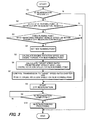
- FIG.3 is a flowchart describing a control routine relating to DPF regeneration executed by a controller.
- FIG.4 is a map showing the running range of the diesel engine in which DPF regeneration is possible in a continuously variable transmission (CVT), and defines the relation between engine rotation speed and engine torque for every vehicle speed.
- CVT continuously variable transmission
- FIG.6 is a map showing a post injection characteristic when engine rotation speed is fixed, and defines the relation between engine torque and fuel injection amount of the post injection.
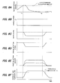
- FIG.7 is a time chart describing DPF regeneration control and its effect according to a first embodiment.
- FIG.7A shows a PM deposition amount as a function of time.
- FIG.7B shows vehicle speed as a function of time.
- FIG.7C shows speed ratio as a function of time.
- FIG.7D shows engine rotation speed as a function of time.
- FIG.7E shows post-injection amount as a function of time.
- FIG.7F shows exhaust gas temperature as a function of time.
- FIG.8 is a time chart describing DPF regeneration control and its effect according to a second embodiment.
- FIG.8A shows a PM deposition amount as a function of time.
- FIG.8B shows vehicle speed as a function of time.
- FIG.8C shows speed ratio as a function of time.
- FIG.8D shows engine rotation speed as a function of time.
- FIG.8E shows post-injection amount as a function of time.
- FIG.8F shows exhaust gas temperature as a function of time.
- FIG.10 is a time chart describing DPF regeneration control and its effect according to a third embodiment.
- FIG.10A shows a PM deposition amount as a function of time.
- FIG. 10B shows vehicle speed as a function of time.
- FIG.10C shows speed ratio as a function of time.
- FIG. 10D shows engine rotation speed as a function of time.
- FIG.10E shows post-injection amount as a function of time.
- FIG.10F shows exhaust gas temperature as a function of time.
- FIG. 11 is a shift map of a gear transmission.
- FIG. 12 is a diagram showing the running range of the diesel engine in which DPF regeneration is possible in the gear transmission, and defines the relation between engine rotation speed and engine torque for every vehicle speed.
- the diesel particulate filter purifies the exhaust gas from a vehicle diesel engine.
- a DPF11 is a filter which traps particulate matter (PM) in the exhaust gas discharged from the diesel engine 20, for example, a ceramic porous filter.
- the DPF11 is installed in the exhaust system for the diesel engine 20. If the DPF11 continues to trap the PM, it will become clogged. Once PM accumulates to some extent, the exhaust gas temperature is increased by controlling the fuel injection of the fuel injector 22. This burns and removes the deposited PM, and regenerates the DPF. The regeneration characteristics of the DPF11 are described later.
- the differential pressure sensor 12 is a pressure difference measurement means for detecting the differential pressure dP between the pressure on the inlet side and the outlet side of the DPF11. The amount of trapped PM is estimated from the magnitude of the differential pressure, and thus the differential pressure sensor 12 assists the controller 40 in determining the regeneration timing of the DPF.
- the differential pressure sensor 12 outputs the detected differential pressure signal to the controller 40.
- the differential pressure sensor 12 is an example of the condition detecting sensor which detects a condition of the DPF11. When the condition of the DPF11 becomes a predetermined condition, the controller 40 determines that regeneration of DPF 11 is required.
- the condition of the DPF11 means the differential pressure and the predetermined condition corresponds to an experimentally predetermined value of the differential pressure.
- the DPF inlet temperature sensor 13 is a temperature measurement means for detecting the inlet temperature Ti (i.e., the exhaust gas temperature of the diesel engine 20) of the DPF11, and outputs a signal indicative of the inlet temperature to the controller 40.
- a DPF outlet temperature sensor 14 is a temperature measurement means for detecting the outlet temperature To of the DPF11, and outputs an signal indicative of the outlet temperature to the controller 40.
- the vehicle speed sensor 27 is a vehicle speed ( Vsp ) measurement means, and may be a sensor which detects the rotation speed of the output shaft of the automatic transmission 30.
- the engine speed sensor 28 is an engine rotation speed ( Ne ) measurement means, and may be a sensor which detects the rotation speed of the output shaft of a diesel engine 20.
- the signals from the sensors 12-14 and 27-28 are inputted to the controller 40.
- the controller 40 functions as a running point determining means. When the controller 40 determines that regeneration of the DPF11 is required, it determines whether or not the running point of the diesel engine 20 is in a temperature region in which self-ignition of particulates is possible.
- "running point” is a set of engine rotation speed Ne and engine torque ETor (engine load) i.e., ( Ne, ETor ).
- Ne, ETor engine load
- the controller 40 sets a new running point while maintaining vehicle speed Vsp . Thus, it functions as a running point setting means of the diesel engine 20.
- the new running point is a running point at which hot exhaust gas can be discharged to raise the particulates to the self-ignition temperature, and the same vehicle speed is maintained at the new running point and the original running point.
- the controller 40 determines whether there is the new running point at which hot exhaust gas can be discharged to raise the particulates to self-ignition temperature.
- the controller 40 changes the speed ratio of the automatic transmission 30 so as to realize the set new running point.
- the controller 40 determines a target speed ratio based on the engine rotation speed corresponding to the new running point and the vehicle speed. In this way, the controller 40 further functions as a target speed ratio determination means.
- the controller 40 controls the automatic transmission 30 so that the target speed ratio is obtained.
- the controller 40 further functions as a speed ratio change means.
- the controller 40 controls a throttle valve 21 of the diesel engine 20, the fuel injector 22 of the diesel engine 20 and transmission 30, and changes the engine rotation speed.
- the controller 40 further controls the fuel injection timing and injection amount, and performs post-injection and injection timing retardation if required. The details of the control performed by the controller 40 will be described later.
- FIG.2 is a graph showing the regeneration characteristics of the DPF. Exhaust gas temperature is shown on the horizontal axis, and DPF regeneration rate is shown on the vertical axis. As shown in FIG.2, when the exhaust gas temperature Ti is a low temperature, the DPF cannot be regenerated, but when the exhaust gas temperature is higher than a threshold temperature Te , the PM bums and the DPF can be regenerated. The DPF regeneration rate also increases with the rise of exhaust gas temperature. For example, the threshold temperature Te is 400 degrees C.
- a step S1 the controller 40 determines whether or not regeneration of the DPF11 is required. If regeneration is required, the routine proceeds to a step S2. If regeneration is unnecessary, the routine is terminated.
- the need for regeneration of the DPF is determined from the magnitude of the differential pressure dP at the inlet and outlet of the DPF detected by the differential pressure sensor 12. When the differential pressure is larger than a predetermined value due to clogging of the DPF (i.e. when the PM deposition amount exceeds a predetermined PM deposition amount that requires the start of regeneration), it is determined that regeneration of DPF is required.
- the predetermined value or the predetermined PM deposition amount is experimentally determined depending on the construction of the DPF.
- step S2 it is determined whether or not the present running point of the diesel engine 20 is in a running range where regeneration of the DPF is difficult. This determination is performed by looking up the map of FIG.4.
- the map of FIG. 4 is stored in the ROM of the controller 40, and defines the relation between engine rotation speed and engine torque for every vehicle speed.
- FIG. 4 shows the running range in which DPF regeneration is possible within an engine rotation speed-engine torque plane. The engine rotation speed is shown on the horizontal axis, and engine torque (engine load) is shown on the vertical axis.
- the running range in which DPF regeneration is possible can be experimentally determined beforehand.
- the bold curves show isovalue curves for the vehicle speed Vsp. In other words, a constant vehicle speed can be maintained at all running points on each isovalue curve.
- the dot-and-dash curve shows the boundary 50 of the running range in which the exhaust gas temperature Ti can reach a temperature higher than the threshold temperature Te .
- the engine running range above the boundary 50 is referred to as "feasible DPF regeneration region" in this description.
- the exhaust gas temperature can rise to a temperature (higher than the threshold temperature Te) at which PM can burn by a suitable "post-injection” or suitable “injection timing retardation” which does not cause problems, such as fuel adhesion to the wall of the cylinder liner.
- the engine running range below the boundary 50 is an engine running range wherein even if "post-injection” and “injection timing retardation” are performed, DPF regeneration is difficult, because either PM cannot be burned or problems such as fuel adhesion to the wall of the cylinder liner arise.
- This range is referred to as "difficult DPF regeneration range” in this description.
- the running point A in FIG.4 is in the feasible DPF regeneration region, whereas the running points B and C are in the difficult DPF regeneration region.
- Step S2 it is determined whether or not the present running point is in the difficult DPF regeneration region by looking up the map of FIG.4.
- the present vehicle speed Vsp is read from the vehicle speed sensor 27 and the present engine rotation speed Ne is read from the engine speed sensor 28.
- the present engine torque Etor is obtained from the present vehicle speed Vsp and the present engine rotation speed Ne by looking up the map of FIG.4, whereby the present running point ( Ne , ETor ) of the diesel engine 20 is found. If the running point of the diesel engine 20 is not in the difficult DPF regeneration region (i.e., the running point is in the feasible DPF regeneration region), the routine proceeds to a Step S8, and if the running point of the diesel engine 20 is in the difficult DPF regeneration region, the routine proceeds to a Step S3.
- a step S3 the present vehicle speed is read by using the vehicle speed sensor 27, and then, referring to FIG.4, it is determined whether or not the isovalue curve which maintains the present vehicle speed, passes through the feasible DPF regeneration region.
- a running point is searched which maintains the present vehicle speed and is suitable for DPF regeneration.
- the routine proceeds to the Step S8.
- the routine proceeds to a Step S4 for changing running point.
- a step S4 the map of FIG.4 is looked up and a new running point maintaining the present vehicle speed is set.
- a modification of the running point is performed.
- the present running point is the point B in FIG. 4.
- the present running point B is changed and a new running point D is set.
- the new running point D is determined in consideration of both viewpoints.
- the running point D may be separated from the intersection of isovalue curve for the present speed and the boundary 50 by only a predetermined distance.
- step S5 the engine rotation speed NeD and engine torque TD for the new running point D are calculated from the map of FIG.4.
- a target speed ratio is calculated from a present vehicle speed V3 and engine rotation speed NeD for the new running point D. This may be calculated for example by looking up a shift map shown in FIG.5 stored in a ROM.
- the lines in FIG.5 show 1st-4th gear (Gr 1-4) of the manual mode of the CVT.
- the slope of the line on the Lo side (high speed ratio) is steep, and the slope of the line on the Hi side (low speed ratio) is gradual.
- the speed change of the CVT is performed by changing the ratio of the radii of the pair of pulleys.
- Step S6 the target speed ratio for the vehicle speed Vsp and the engine rotation speed NeD of the running point D are calculated based on the shift map of FIG.5.
- a command signal to decrease the speed ratio is sent to the automatic transmission 30 (CVT), and a command signal to lower the engine rotation speed is sent to the engine (throttle valve 21, fuel injector 22).
- the engine rotation speed NeD is realized and the speed ratio of the automatic transmission 30 is controlled to the target speed ratio.
- step S8 regeneration of the DPF is started.
- the map of FIG.6 is looked up and "post-injection" is performed.
- the post injection amount ID for the post injection is the fuel injection amount required for DPF regeneration. Since a large engine torque increases the exhaust gas temperature, the post injection amount ID decreases as the engine torque TD for the new running point D increases.
- the post injection amount ID relative to the engine torque TD found in the step S5 can be calculated using this map.
- post-injection is started by calculating the post-injection amount ID required for DPF regeneration based on the map of FIG.6.
- the effect of the control of this embodiment on the CVT will now be described referring to the time charts of FIG.7A-F.
- the solid line relates to the control of this embodiment, and the dashed line relates to the case where the control of this embodiment is not performed (where speed change control is not performed).
- the exhaust gas temperature may be increased to a temperature above the threshold temperature Te at which DPF regeneration is possible (FIG.7F), while maintaining a fixed vehicle speed (FIG.7B) and without changing the speed ratio or engine rotation speed (dashed lines of FIG.7C and D).
- the fuel injection amount of the post-injection must be sharply increased (dashed line of FIG.7E). If the post-injection amount is increased, fuel consumption will be impaired.
- the control of this embodiment can perform filter regeneration processing by changing the running point of the engine so that the exhaust gas temperature will be high, even when the engine load is small and the exhaust gas temperature is low.
- the injection amount of the "post-injection” can be reduced as compared with the prior art in which the running point of the engine is not changed. In this way, the control of this embodiment has the effect of improving fuel consumption.
- DPF regeneration processing is performed not by post-injection but by "injection timing retardation”.
- the controller 40 controls the fuel injector 22 to delay fuel injection timing.
- the retardation amount RD required for DPF regeneration is found by looking up the map of FIG.9 according to the engine torque TD calculated in the step S5.
- the map of FIG. 9 is stored in the ROM, and determines the relation between the retardation amount RD of the fuel injection timing, and the engine torque Etor .
- the retardation amount RD decreases as the engine torque TD for the new running point D increases.
- the retardation amount can be made small.
- this embodiment describes the DPF regeneration control for a gear transmission.
- the control routine is identical to that of FIG.3.
- PM is deposited with passing time.
- the control of the steps S2-S10 is started (time t1; Step S1).
- the speed ratio is shifted to the Hi side (solid line of FIG.10C; Step S7), and thus the engine rotation speed is reduced (FIG.10D; Step S7).
- a post-injection is performed at the speed ratio and engine rotation speed set in the steps S4-S7 (FIG.10E; Step S8).
- This control can raise the exhaust gas temperature to a temperature above the threshold temperature Te at which DPF regeneration can be started (FIG.10F).
- the exhaust gas temperature can be increased to a temperature higher than the DPF regeneration temperature Te without increasing the post-injection amount largely, and therefore, fuel cost-performance can be improved.
- post-injection and injection timing retardation are performed together with change of running point (change of engine rotation speed and speed ratio), post-injection and injection timing retardation are not necessary if the change of the running point enables the exhaust gas temperature to increase to a temperature higher than the DPF regeneration temperature Te by itself. Further, injection timing retardation may also be performed to raise the exhaust gas temperature in a gear transmission.
Applications Claiming Priority (2)
| Application Number | Priority Date | Filing Date | Title |
|---|---|---|---|
| JP2003001347 | 2003-01-07 | ||
| JP2003001347A JP2004211638A (ja) | 2003-01-07 | 2003-01-07 | ディーゼルエンジンのフィルタ再生制御装置 |
Publications (2)
| Publication Number | Publication Date |
|---|---|
| EP1437492A1 true EP1437492A1 (fr) | 2004-07-14 |
| EP1437492B1 EP1437492B1 (fr) | 2006-03-29 |
Family
ID=32501195
Family Applications (1)
| Application Number | Title | Priority Date | Filing Date |
|---|---|---|---|
| EP04000076A Expired - Fee Related EP1437492B1 (fr) | 2003-01-07 | 2004-01-05 | Régénération d'un filtre à particules |
Country Status (5)
| Country | Link |
|---|---|
| US (1) | US6971970B2 (fr) |
| EP (1) | EP1437492B1 (fr) |
| JP (1) | JP2004211638A (fr) |
| CN (1) | CN1517520A (fr) |
| DE (1) | DE602004000534T2 (fr) |
Cited By (18)
| Publication number | Priority date | Publication date | Assignee | Title |
|---|---|---|---|---|
| EP1548257A2 (fr) * | 2003-12-19 | 2005-06-29 | Nissan Motor Co., Ltd. | Un système et procédé de regéneration d'un filtre à particles diesel |
| EP1617059A1 (fr) * | 2004-07-16 | 2006-01-18 | Toyota Jidosha Kabushiki Kaisha | Un système de regeneration d'un filtre à particules qui compense d'huile qui est brulé dans dans le cylindre |
| EP1722082A3 (fr) * | 2005-05-13 | 2007-01-03 | HONDA MOTOR CO., Ltd. | Système de régulation des émissions d'un moteur à combustion interne et son procédé de commande |
| FR2890926A1 (fr) * | 2005-09-21 | 2007-03-23 | Renault Sas | Procede d'obtention de gaz d'echappement charges en carburant |
| WO2007042888A1 (fr) * | 2005-10-07 | 2007-04-19 | Eaton Corporation | Systeme de moteur diesel a plage de vitesses etroite pourvu de dispositifs de post-traitement |
| EP1785605A3 (fr) * | 2005-11-11 | 2007-05-30 | Volkswagen Aktiengesellschaft | Procédé de régénération d'un filtre à particules diesel et commande de boîte de vitesses correspondant |
| GB2437627A (en) * | 2006-04-27 | 2007-10-31 | Ford Global Tech Llc | A method of regenerating an emission control device |
| FR2901307A1 (fr) * | 2006-05-16 | 2007-11-23 | Renault Sas | Moteur a combustion interne avec filtre a particules et procede de regeneration d'un tel filtre a particules |
| WO2007145553A1 (fr) | 2006-06-14 | 2007-12-21 | Volvo Lastvagnar Ab | Procédé et système de régénération pour unité de purification de gaz d'échappement |
| WO2008100284A2 (fr) * | 2006-09-29 | 2008-08-21 | Caterpillar Inc. | Systèmes d'alimentation |
| EP2066893A1 (fr) * | 2006-09-15 | 2009-06-10 | Volvo Lastvagnar AB | Limitation d'une fonction de transmission en mode de régénération pour un filtre à particules diesel |
| EP1939434A3 (fr) * | 2006-12-27 | 2010-06-02 | Toyota Jidosha Kabushiki Kaisha | Appareil et procédé de purification d'un filtre à particles |
| CN101988435A (zh) * | 2009-07-31 | 2011-03-23 | 福特环球技术公司 | 运转包括柴油微粒过滤器的发动机的方法 |
| US8505281B2 (en) | 2009-09-30 | 2013-08-13 | Cummins Inc. | Techniques for enhancing aftertreatment regeneration capability |
| US9027327B2 (en) | 2006-06-14 | 2015-05-12 | Volvo Lasivagnar AB | Method and system for regenerating an exhaust gas purification unit |
| EP2905462A3 (fr) * | 2013-12-21 | 2015-11-18 | Andersen, Peter | Procédé de mise en service d'un moteur à combustion interne d'un groupe générateur d'un système de distribution d'énergie électrique à bord d'un bateau |
| EP2617616A4 (fr) * | 2010-09-16 | 2018-05-02 | Yanmar Co., Ltd. | Dispositif de commande de système d'entraînement de véhicule de chantier |
| DE102016216062B4 (de) | 2015-08-31 | 2022-04-14 | Ford Global Technologies, Llc | Optimierte LNT-Diagnose |
Families Citing this family (33)
| Publication number | Priority date | Publication date | Assignee | Title |
|---|---|---|---|---|
| JP4148178B2 (ja) * | 2004-04-08 | 2008-09-10 | いすゞ自動車株式会社 | 排気ガス浄化システムの制御方法及び排気ガス浄化システム |
| JP4810922B2 (ja) * | 2004-08-10 | 2011-11-09 | 日産自動車株式会社 | Pm堆積量推定制御装置 |
| JP2006283709A (ja) | 2005-04-01 | 2006-10-19 | Toyota Motor Corp | 内燃機関の制御装置 |
| US7406822B2 (en) * | 2005-06-30 | 2008-08-05 | Caterpillar Inc. | Particulate trap regeneration system and control strategy |
| US7628009B2 (en) * | 2005-10-07 | 2009-12-08 | Eaton Corporation | Exhaust aftertreatment system with transmission control |
| US20070079605A1 (en) * | 2005-10-07 | 2007-04-12 | Eaton Corporation | Exhaust aftertreatment system with transmission control |
| JP4428361B2 (ja) * | 2006-05-24 | 2010-03-10 | トヨタ自動車株式会社 | 内燃機関の排気浄化システム |
| JP4905303B2 (ja) * | 2006-10-02 | 2012-03-28 | 日産自動車株式会社 | 内燃機関の排出ガス温度制御方法及び装置並びに内燃機関システム |
| DE102006053104B4 (de) * | 2006-11-10 | 2019-10-31 | Robert Bosch Gmbh | Verfahren zur Anpassung eines Kennfeldes |
| JP4750062B2 (ja) * | 2007-03-06 | 2011-08-17 | ヤンマー株式会社 | ディーゼルエンジン制御方法 |
| JP4665924B2 (ja) * | 2007-03-16 | 2011-04-06 | トヨタ自動車株式会社 | 内燃機関の排気浄化システム |
| DE102007033678B4 (de) * | 2007-07-19 | 2022-08-11 | Robert Bosch Gmbh | Verfahren und Vorrichtung zur Steuerung einer Brennkraftmaschine |
| US8042325B2 (en) * | 2007-11-01 | 2011-10-25 | Ford Global Technologies, Llc | Adapting indicated engine torque during regeneration of a diesel particulate filter |
| US8277363B2 (en) * | 2007-11-07 | 2012-10-02 | GM Global Technology Operations LLC | Method and apparatus to control temperature of an exhaust aftertreatment system for a hybrid powertrain |
| DE102008058010B4 (de) * | 2008-11-19 | 2015-03-12 | Continental Automotive Gmbh | Verfahren und Vorrichtung zum Betreiben einer Brennkraftmaschine |
| JP5215940B2 (ja) | 2009-05-28 | 2013-06-19 | 富士重工業株式会社 | エンジン及び無段変速機の協調制御装置 |
| US8615989B2 (en) | 2010-01-25 | 2013-12-31 | Deere & Company | Method for regeneration of diesel particulate filter in an exhaust aftertreatment system of an IC engine |
| JPWO2011093400A1 (ja) * | 2010-01-28 | 2013-06-06 | 日立建機株式会社 | 油圧作業機械の排気ガス浄化システム |
| US8959898B2 (en) * | 2011-04-26 | 2015-02-24 | GM Global Technology Operations LLC | Regeneration methods and systems for particulate filters |
| JP5843154B2 (ja) * | 2012-01-10 | 2016-01-13 | 三菱ふそうトラック・バス株式会社 | 排ガス浄化装置及びその制御方法 |
| BR112015007438B1 (pt) | 2012-10-02 | 2022-01-18 | Scania Cv Ab | Método para regulação de uma temperatura em um sistema de pós-tratamento de exaustão, sistema para controle de linha de transmissão, e veículo |
| SE539215C2 (sv) * | 2012-10-02 | 2017-05-16 | Scania Cv Ab | Reglering av en temperatur i ett avgassystem |
| JP6217398B2 (ja) * | 2014-01-09 | 2017-10-25 | マツダ株式会社 | ディーゼルエンジンの燃料噴射制御装置 |
| US10487715B2 (en) * | 2015-08-20 | 2019-11-26 | Ford Global Technologies, Llc | Regeneration of particulate filters in autonomously controllable vehicles |
| JP6568485B2 (ja) * | 2016-02-04 | 2019-08-28 | 本田技研工業株式会社 | 内燃機関の制御装置 |
| US10344657B2 (en) | 2016-02-12 | 2019-07-09 | GM Global Technology Operations LLC | System and method for particulate filter regeneration |
| CN106150718B (zh) * | 2016-08-31 | 2019-07-05 | 潍柴动力股份有限公司 | 一种发动机档位优化方法及装置 |
| JP6673271B2 (ja) * | 2017-03-22 | 2020-03-25 | トヨタ自動車株式会社 | 自動車 |
| EP3645851A1 (fr) * | 2017-06-29 | 2020-05-06 | Volvo Truck Corporation | Procédé de commande d'un système de propulsion de véhicule |
| CN107120198B (zh) * | 2017-07-12 | 2023-11-28 | 恒天九五重工有限公司 | 液压工程机械发动机排放控制装置及方法 |
| CN111173595B (zh) * | 2020-01-19 | 2021-02-09 | 中国第一汽车股份有限公司 | 一种颗粒捕集装置再生系统及其控制方法 |
| CN114810384B (zh) * | 2022-05-10 | 2023-05-23 | 潍柴动力股份有限公司 | 后处理入口温度的控制方法以及装置 |
| CN115324757B (zh) * | 2022-09-05 | 2023-11-17 | 潍柴动力股份有限公司 | Dpf被动再生的控制方法、控制装置与电子控制单元 |
Citations (3)
| Publication number | Priority date | Publication date | Assignee | Title |
|---|---|---|---|---|
| WO2001053664A2 (fr) * | 2000-01-19 | 2001-07-26 | Volkswagen Aktiengesellschaft | Procede pour l'augmentation temporaire d'une temperature des gaz d'echappement d'un moteur a combustion interne |
| FR2820462A1 (fr) * | 2001-02-06 | 2002-08-09 | Peugeot Citroen Automobiles Sa | Systeme d'aide a la regeneration d'un filtre a particules integre dans une ligne d'echappement d'un moteur diesel de vehicule automobile |
| EP1382812A1 (fr) * | 2002-07-15 | 2004-01-21 | Mazda Motor Corporation | Système de post-traitement de particules provenant d'un moteur à combustion interne et logiciel correspondant |
Family Cites Families (10)
| Publication number | Priority date | Publication date | Assignee | Title |
|---|---|---|---|---|
| US751883A (en) * | 1904-02-09 | Heney b | ||
| US752518A (en) * | 1904-02-16 | James p | ||
| US752519A (en) * | 1904-02-16 | Wagon-unloading mechanism | ||
| US755316A (en) * | 1903-05-29 | 1904-03-22 | Joseph G Ranger Jr | Wheel. |
| US756502A (en) * | 1903-10-29 | 1904-04-05 | Frederick H Bartlett | Mechanism for removing ice from electric conductors. |
| JP2891028B2 (ja) | 1993-03-03 | 1999-05-17 | 日産自動車株式会社 | 無段変速機の制御装置 |
| JP3678282B2 (ja) | 1996-08-30 | 2005-08-03 | 株式会社デンソー | 内燃機関の排ガス浄化用触媒の温度制御装置 |
| JP3512010B2 (ja) * | 2001-02-06 | 2004-03-29 | トヨタ自動車株式会社 | 筒内噴射式内燃機関の制御装置 |
| US6866610B2 (en) * | 2001-03-30 | 2005-03-15 | Toyota Jidosha Kabushiki Kaisha | Control apparatus and method for vehicle having internal combustion engine and continuously variable transmission, and control apparatus and method for internal combustion engine |
| US6738702B2 (en) * | 2002-08-29 | 2004-05-18 | Ford Global Technologies, Llc | Method for particulate filter regeneration in vehicles having an automatically controlled transmission |
-
2003
- 2003-01-07 JP JP2003001347A patent/JP2004211638A/ja active Pending
-
2004
- 2004-01-05 DE DE602004000534T patent/DE602004000534T2/de not_active Expired - Fee Related
- 2004-01-05 EP EP04000076A patent/EP1437492B1/fr not_active Expired - Fee Related
- 2004-01-07 US US10/752,427 patent/US6971970B2/en not_active Expired - Fee Related
- 2004-01-07 CN CNA2004100014000A patent/CN1517520A/zh active Pending
Patent Citations (3)
| Publication number | Priority date | Publication date | Assignee | Title |
|---|---|---|---|---|
| WO2001053664A2 (fr) * | 2000-01-19 | 2001-07-26 | Volkswagen Aktiengesellschaft | Procede pour l'augmentation temporaire d'une temperature des gaz d'echappement d'un moteur a combustion interne |
| FR2820462A1 (fr) * | 2001-02-06 | 2002-08-09 | Peugeot Citroen Automobiles Sa | Systeme d'aide a la regeneration d'un filtre a particules integre dans une ligne d'echappement d'un moteur diesel de vehicule automobile |
| EP1382812A1 (fr) * | 2002-07-15 | 2004-01-21 | Mazda Motor Corporation | Système de post-traitement de particules provenant d'un moteur à combustion interne et logiciel correspondant |
Cited By (31)
| Publication number | Priority date | Publication date | Assignee | Title |
|---|---|---|---|---|
| US7322182B2 (en) | 2003-12-19 | 2008-01-29 | Nissan Motor Co., Ltd. | Filter regeneration control |
| EP1548257A3 (fr) * | 2003-12-19 | 2005-07-06 | Nissan Motor Co., Ltd. | Un système et procédé de regéneration d'un filtre à particles diesel |
| EP1548257A2 (fr) * | 2003-12-19 | 2005-06-29 | Nissan Motor Co., Ltd. | Un système et procédé de regéneration d'un filtre à particles diesel |
| EP1617059A1 (fr) * | 2004-07-16 | 2006-01-18 | Toyota Jidosha Kabushiki Kaisha | Un système de regeneration d'un filtre à particules qui compense d'huile qui est brulé dans dans le cylindre |
| EP1722082A3 (fr) * | 2005-05-13 | 2007-01-03 | HONDA MOTOR CO., Ltd. | Système de régulation des émissions d'un moteur à combustion interne et son procédé de commande |
| FR2890926A1 (fr) * | 2005-09-21 | 2007-03-23 | Renault Sas | Procede d'obtention de gaz d'echappement charges en carburant |
| WO2007034119A1 (fr) * | 2005-09-21 | 2007-03-29 | Renault S.A.S. | Procede d'obtention de gaz d'echappement charges en carburant et vehicule automobile associe |
| US8366586B2 (en) | 2005-09-21 | 2013-02-05 | Renault S.A.S. | Method for obtaining fuel-loaded exhaust gases and related motor vehicle |
| WO2007042888A1 (fr) * | 2005-10-07 | 2007-04-19 | Eaton Corporation | Systeme de moteur diesel a plage de vitesses etroite pourvu de dispositifs de post-traitement |
| EP1785605A3 (fr) * | 2005-11-11 | 2007-05-30 | Volkswagen Aktiengesellschaft | Procédé de régénération d'un filtre à particules diesel et commande de boîte de vitesses correspondant |
| US7469533B2 (en) | 2006-04-27 | 2008-12-30 | Ford Global Technologies, Llc | Brake torque load generation process for diesel particulate filter regeneration and SOx removal from lean NOx trap |
| GB2437627A (en) * | 2006-04-27 | 2007-10-31 | Ford Global Tech Llc | A method of regenerating an emission control device |
| FR2901307A1 (fr) * | 2006-05-16 | 2007-11-23 | Renault Sas | Moteur a combustion interne avec filtre a particules et procede de regeneration d'un tel filtre a particules |
| US9027327B2 (en) | 2006-06-14 | 2015-05-12 | Volvo Lasivagnar AB | Method and system for regenerating an exhaust gas purification unit |
| EP2041406A1 (fr) * | 2006-06-14 | 2009-04-01 | Volvo Lastvagnar AB | Procédé et système de régénération pour unité de purification de gaz d'échappement |
| EP2041406B1 (fr) | 2006-06-14 | 2018-02-14 | Volvo Lastvagnar AB | Procédé et système de régénération pour unité de purification de gaz d'échappement |
| EP2041406A4 (fr) * | 2006-06-14 | 2015-03-18 | Volvo Lastvagnar Ab | Procédé et système de régénération pour unité de purification de gaz d'échappement |
| WO2007145553A1 (fr) | 2006-06-14 | 2007-12-21 | Volvo Lastvagnar Ab | Procédé et système de régénération pour unité de purification de gaz d'échappement |
| EP2066893A1 (fr) * | 2006-09-15 | 2009-06-10 | Volvo Lastvagnar AB | Limitation d'une fonction de transmission en mode de régénération pour un filtre à particules diesel |
| EP2066893A4 (fr) * | 2006-09-15 | 2013-01-09 | Volvo Lastvagnar Ab | Limitation d'une fonction de transmission en mode de régénération pour un filtre à particules diesel |
| WO2008100284A2 (fr) * | 2006-09-29 | 2008-08-21 | Caterpillar Inc. | Systèmes d'alimentation |
| WO2008100284A3 (fr) * | 2006-09-29 | 2009-02-19 | Caterpillar Inc | Systèmes d'alimentation |
| EP1939434A3 (fr) * | 2006-12-27 | 2010-06-02 | Toyota Jidosha Kabushiki Kaisha | Appareil et procédé de purification d'un filtre à particles |
| US7946955B2 (en) | 2006-12-27 | 2011-05-24 | Toyota Jidosha Kabushiki Kaisha | Vehicle control apparatus and method |
| CN101988435B (zh) * | 2009-07-31 | 2016-07-13 | 福特环球技术公司 | 运转包括柴油微粒过滤器的发动机的方法 |
| CN101988435A (zh) * | 2009-07-31 | 2011-03-23 | 福特环球技术公司 | 运转包括柴油微粒过滤器的发动机的方法 |
| US8505281B2 (en) | 2009-09-30 | 2013-08-13 | Cummins Inc. | Techniques for enhancing aftertreatment regeneration capability |
| US8752364B2 (en) | 2009-09-30 | 2014-06-17 | Cummins Inc. | Techniques for optimizing engine operations during aftertreatment regeneration |
| EP2617616A4 (fr) * | 2010-09-16 | 2018-05-02 | Yanmar Co., Ltd. | Dispositif de commande de système d'entraînement de véhicule de chantier |
| EP2905462A3 (fr) * | 2013-12-21 | 2015-11-18 | Andersen, Peter | Procédé de mise en service d'un moteur à combustion interne d'un groupe générateur d'un système de distribution d'énergie électrique à bord d'un bateau |
| DE102016216062B4 (de) | 2015-08-31 | 2022-04-14 | Ford Global Technologies, Llc | Optimierte LNT-Diagnose |
Also Published As
| Publication number | Publication date |
|---|---|
| US6971970B2 (en) | 2005-12-06 |
| EP1437492B1 (fr) | 2006-03-29 |
| DE602004000534D1 (de) | 2006-05-18 |
| CN1517520A (zh) | 2004-08-04 |
| DE602004000534T2 (de) | 2006-08-17 |
| JP2004211638A (ja) | 2004-07-29 |
| US20040204289A1 (en) | 2004-10-14 |
Similar Documents
| Publication | Publication Date | Title |
|---|---|---|
| US6971970B2 (en) | Regeneration of diesel particulate filter | |
| US7237379B2 (en) | Regeneration of diesel particulate filter | |
| US7200991B2 (en) | Regeneration control of diesel particulate filter | |
| US7219493B2 (en) | Filter regeneration in engine exhaust gas purification device | |
| JP4765914B2 (ja) | 車両用パワートレーンの制御装置 | |
| KR100713054B1 (ko) | 엔진 토크 제어 장치 | |
| US10196065B2 (en) | Vehicle control system | |
| EP1426591A2 (fr) | Régénération de filtre à particules diesel | |
| US20020006848A1 (en) | Apparatus for controlling vehicle drive system including engine with turbocharger, and lock-up clutch | |
| US7389176B2 (en) | Engine output control apparatus of power train | |
| JP2004512467A (ja) | 排ガス後処理システムを制御する方法および装置 | |
| US5101687A (en) | Shift control system and method using a main throttle and a sub throttle valve for torque control for automatic transmissions | |
| CN105383494A (zh) | 车辆控制装置 | |
| EP1865175B1 (fr) | Appareil de contrôle de la sortie d'un moteur d'un groupe moto-propulseur | |
| US7171802B2 (en) | Diesel engine comprising DPM filter and method of estimating amount of DPM trapped in DPM filter | |
| EP1279813A2 (fr) | Dispositif et procédé pour le contrôle de véhicules | |
| US5405303A (en) | Control system for engines and automatic transmissions | |
| US6094613A (en) | Control apparatus and a control method for controlling an automatic transmission of a vehicle | |
| EP1464817B1 (fr) | Appareil et méthode de traitement des gaz d'échappement pour moteur diesel | |
| JP2000161044A (ja) | パティキュレートフィルタの再生制御装置 | |
| FR2846048A1 (fr) | Procede et dispositif de commande d'une unite motrice munie d'un moteur a combustion interne | |
| JP4140134B2 (ja) | エンジンの制御装置 | |
| JP2005207242A (ja) | パティキュレートフィルタの再生処理制御装置 | |
| FR2869645A1 (fr) | Procede de gestion d'un dispositif de traitement des gaz d'echappement | |
| JPH02218826A (ja) | 自動変速機を備えた車両のエンジン制御装置 |
Legal Events
| Date | Code | Title | Description |
|---|---|---|---|
| PUAI | Public reference made under article 153(3) epc to a published international application that has entered the european phase |
Free format text: ORIGINAL CODE: 0009012 |
|
| 17P | Request for examination filed |
Effective date: 20040105 |
|
| AK | Designated contracting states |
Kind code of ref document: A1 Designated state(s): AT BE BG CH CY CZ DE DK EE ES FI FR GB GR HU IE IT LI LU MC NL PT RO SE SI SK TR |
|
| AX | Request for extension of the european patent |
Extension state: AL LT LV MK |
|
| 17Q | First examination report despatched |
Effective date: 20040902 |
|
| AKX | Designation fees paid |
Designated state(s): DE FR GB |
|
| GRAP | Despatch of communication of intention to grant a patent |
Free format text: ORIGINAL CODE: EPIDOSNIGR1 |
|
| RIN1 | Information on inventor provided before grant (corrected) |
Inventor name: TABATA, MUNEHIRO Inventor name: KONDOU, TERUNORI Inventor name: TSUTSUMOTO, NAOYA Inventor name: INOUE, TAKAO Inventor name: KAWASHIMA, JUNICHI Inventor name: OTAKE, MAKOTO |
|
| GRAS | Grant fee paid |
Free format text: ORIGINAL CODE: EPIDOSNIGR3 |
|
| GRAA | (expected) grant |
Free format text: ORIGINAL CODE: 0009210 |
|
| AK | Designated contracting states |
Kind code of ref document: B1 Designated state(s): DE FR GB |
|
| REG | Reference to a national code |
Ref country code: GB Ref legal event code: FG4D |
|
| RIC1 | Information provided on ipc code assigned before grant |
Ipc: F16H 61/02 20060101ALI20060206BHEP Ipc: F01N 9/00 20060101AFI20060206BHEP Ipc: F01N 3/025 20060101ALI20060206BHEP Ipc: F01N 3/023 20060101ALI20060206BHEP Ipc: F02D 41/40 20060101ALI20060206BHEP Ipc: F02D 41/02 20060101ALI20060206BHEP |
|
| REF | Corresponds to: |
Ref document number: 602004000534 Country of ref document: DE Date of ref document: 20060518 Kind code of ref document: P |
|
| PLBE | No opposition filed within time limit |
Free format text: ORIGINAL CODE: 0009261 |
|
| STAA | Information on the status of an ep patent application or granted ep patent |
Free format text: STATUS: NO OPPOSITION FILED WITHIN TIME LIMIT |
|
| 26N | No opposition filed |
Effective date: 20070102 |
|
| EN | Fr: translation not filed | ||
| PG25 | Lapsed in a contracting state [announced via postgrant information from national office to epo] |
Ref country code: DE Free format text: LAPSE BECAUSE OF NON-PAYMENT OF DUE FEES Effective date: 20070801 |
|
| PG25 | Lapsed in a contracting state [announced via postgrant information from national office to epo] |
Ref country code: FR Free format text: LAPSE BECAUSE OF FAILURE TO SUBMIT A TRANSLATION OF THE DESCRIPTION OR TO PAY THE FEE WITHIN THE PRESCRIBED TIME-LIMIT Effective date: 20070309 |
|
| GBPC | Gb: european patent ceased through non-payment of renewal fee |
Effective date: 20080105 |
|
| PG25 | Lapsed in a contracting state [announced via postgrant information from national office to epo] |
Ref country code: FR Free format text: LAPSE BECAUSE OF FAILURE TO SUBMIT A TRANSLATION OF THE DESCRIPTION OR TO PAY THE FEE WITHIN THE PRESCRIBED TIME-LIMIT Effective date: 20060329 |
|
| PG25 | Lapsed in a contracting state [announced via postgrant information from national office to epo] |
Ref country code: GB Free format text: LAPSE BECAUSE OF NON-PAYMENT OF DUE FEES Effective date: 20080105 |