EP1437492A1 - Regeneration of diesel particulate filter - Google Patents
Regeneration of diesel particulate filter Download PDFInfo
- Publication number
- EP1437492A1 EP1437492A1 EP20040000076 EP04000076A EP1437492A1 EP 1437492 A1 EP1437492 A1 EP 1437492A1 EP 20040000076 EP20040000076 EP 20040000076 EP 04000076 A EP04000076 A EP 04000076A EP 1437492 A1 EP1437492 A1 EP 1437492A1
- Authority
- EP
- European Patent Office
- Prior art keywords
- regeneration
- speed ratio
- engine
- point
- diesel engine
- Prior art date
- Legal status (The legal status is an assumption and is not a legal conclusion. Google has not performed a legal analysis and makes no representation as to the accuracy of the status listed.)
- Granted
Links
Images


Classifications
-
- B—PERFORMING OPERATIONS; TRANSPORTING
- B60—VEHICLES IN GENERAL
- B60W—CONJOINT CONTROL OF VEHICLE SUB-UNITS OF DIFFERENT TYPE OR DIFFERENT FUNCTION; CONTROL SYSTEMS SPECIALLY ADAPTED FOR HYBRID VEHICLES; ROAD VEHICLE DRIVE CONTROL SYSTEMS FOR PURPOSES NOT RELATED TO THE CONTROL OF A PARTICULAR SUB-UNIT
- B60W10/00—Conjoint control of vehicle sub-units of different type or different function
- B60W10/04—Conjoint control of vehicle sub-units of different type or different function including control of propulsion units
- B60W10/06—Conjoint control of vehicle sub-units of different type or different function including control of propulsion units including control of combustion engines
-
- B—PERFORMING OPERATIONS; TRANSPORTING
- B60—VEHICLES IN GENERAL
- B60W—CONJOINT CONTROL OF VEHICLE SUB-UNITS OF DIFFERENT TYPE OR DIFFERENT FUNCTION; CONTROL SYSTEMS SPECIALLY ADAPTED FOR HYBRID VEHICLES; ROAD VEHICLE DRIVE CONTROL SYSTEMS FOR PURPOSES NOT RELATED TO THE CONTROL OF A PARTICULAR SUB-UNIT
- B60W10/00—Conjoint control of vehicle sub-units of different type or different function
- B60W10/04—Conjoint control of vehicle sub-units of different type or different function including control of propulsion units
-
- B—PERFORMING OPERATIONS; TRANSPORTING
- B60—VEHICLES IN GENERAL
- B60W—CONJOINT CONTROL OF VEHICLE SUB-UNITS OF DIFFERENT TYPE OR DIFFERENT FUNCTION; CONTROL SYSTEMS SPECIALLY ADAPTED FOR HYBRID VEHICLES; ROAD VEHICLE DRIVE CONTROL SYSTEMS FOR PURPOSES NOT RELATED TO THE CONTROL OF A PARTICULAR SUB-UNIT
- B60W10/00—Conjoint control of vehicle sub-units of different type or different function
- B60W10/10—Conjoint control of vehicle sub-units of different type or different function including control of change-speed gearings
- B60W10/11—Stepped gearings
-
- B—PERFORMING OPERATIONS; TRANSPORTING
- B60—VEHICLES IN GENERAL
- B60W—CONJOINT CONTROL OF VEHICLE SUB-UNITS OF DIFFERENT TYPE OR DIFFERENT FUNCTION; CONTROL SYSTEMS SPECIALLY ADAPTED FOR HYBRID VEHICLES; ROAD VEHICLE DRIVE CONTROL SYSTEMS FOR PURPOSES NOT RELATED TO THE CONTROL OF A PARTICULAR SUB-UNIT
- B60W30/00—Purposes of road vehicle drive control systems not related to the control of a particular sub-unit, e.g. of systems using conjoint control of vehicle sub-units, or advanced driver assistance systems for ensuring comfort, stability and safety or drive control systems for propelling or retarding the vehicle
- B60W30/18—Propelling the vehicle
- B60W30/1819—Propulsion control with control means using analogue circuits, relays or mechanical links
-
- F—MECHANICAL ENGINEERING; LIGHTING; HEATING; WEAPONS; BLASTING
- F01—MACHINES OR ENGINES IN GENERAL; ENGINE PLANTS IN GENERAL; STEAM ENGINES
- F01N—GAS-FLOW SILENCERS OR EXHAUST APPARATUS FOR MACHINES OR ENGINES IN GENERAL; GAS-FLOW SILENCERS OR EXHAUST APPARATUS FOR INTERNAL COMBUSTION ENGINES
- F01N3/00—Exhaust or silencing apparatus having means for purifying, rendering innocuous, or otherwise treating exhaust
- F01N3/02—Exhaust or silencing apparatus having means for purifying, rendering innocuous, or otherwise treating exhaust for cooling, or for removing solid constituents of, exhaust
- F01N3/021—Exhaust or silencing apparatus having means for purifying, rendering innocuous, or otherwise treating exhaust for cooling, or for removing solid constituents of, exhaust by means of filters
- F01N3/023—Exhaust or silencing apparatus having means for purifying, rendering innocuous, or otherwise treating exhaust for cooling, or for removing solid constituents of, exhaust by means of filters using means for regenerating the filters, e.g. by burning trapped particles
-
- F—MECHANICAL ENGINEERING; LIGHTING; HEATING; WEAPONS; BLASTING
- F01—MACHINES OR ENGINES IN GENERAL; ENGINE PLANTS IN GENERAL; STEAM ENGINES
- F01N—GAS-FLOW SILENCERS OR EXHAUST APPARATUS FOR MACHINES OR ENGINES IN GENERAL; GAS-FLOW SILENCERS OR EXHAUST APPARATUS FOR INTERNAL COMBUSTION ENGINES
- F01N9/00—Electrical control of exhaust gas treating apparatus
- F01N9/002—Electrical control of exhaust gas treating apparatus of filter regeneration, e.g. detection of clogging
-
- F—MECHANICAL ENGINEERING; LIGHTING; HEATING; WEAPONS; BLASTING
- F02—COMBUSTION ENGINES; HOT-GAS OR COMBUSTION-PRODUCT ENGINE PLANTS
- F02D—CONTROLLING COMBUSTION ENGINES
- F02D41/00—Electrical control of supply of combustible mixture or its constituents
- F02D41/02—Circuit arrangements for generating control signals
- F02D41/021—Introducing corrections for particular conditions exterior to the engine
- F02D41/0235—Introducing corrections for particular conditions exterior to the engine in relation with the state of the exhaust gas treating apparatus
- F02D41/024—Introducing corrections for particular conditions exterior to the engine in relation with the state of the exhaust gas treating apparatus to increase temperature of the exhaust gas treating apparatus
- F02D41/0245—Introducing corrections for particular conditions exterior to the engine in relation with the state of the exhaust gas treating apparatus to increase temperature of the exhaust gas treating apparatus by increasing temperature of the exhaust gas leaving the engine
-
- F—MECHANICAL ENGINEERING; LIGHTING; HEATING; WEAPONS; BLASTING
- F02—COMBUSTION ENGINES; HOT-GAS OR COMBUSTION-PRODUCT ENGINE PLANTS
- F02D—CONTROLLING COMBUSTION ENGINES
- F02D41/00—Electrical control of supply of combustible mixture or its constituents
- F02D41/02—Circuit arrangements for generating control signals
- F02D41/021—Introducing corrections for particular conditions exterior to the engine
- F02D41/0235—Introducing corrections for particular conditions exterior to the engine in relation with the state of the exhaust gas treating apparatus
- F02D41/027—Introducing corrections for particular conditions exterior to the engine in relation with the state of the exhaust gas treating apparatus to purge or regenerate the exhaust gas treating apparatus
- F02D41/029—Introducing corrections for particular conditions exterior to the engine in relation with the state of the exhaust gas treating apparatus to purge or regenerate the exhaust gas treating apparatus the exhaust gas treating apparatus being a particulate filter
-
- F—MECHANICAL ENGINEERING; LIGHTING; HEATING; WEAPONS; BLASTING
- F02—COMBUSTION ENGINES; HOT-GAS OR COMBUSTION-PRODUCT ENGINE PLANTS
- F02D—CONTROLLING COMBUSTION ENGINES
- F02D41/00—Electrical control of supply of combustible mixture or its constituents
- F02D41/02—Circuit arrangements for generating control signals
- F02D41/14—Introducing closed-loop corrections
- F02D41/1438—Introducing closed-loop corrections using means for determining characteristics of the combustion gases; Sensors therefor
- F02D41/1444—Introducing closed-loop corrections using means for determining characteristics of the combustion gases; Sensors therefor characterised by the characteristics of the combustion gases
- F02D41/1448—Introducing closed-loop corrections using means for determining characteristics of the combustion gases; Sensors therefor characterised by the characteristics of the combustion gases the characteristics being an exhaust gas pressure
-
- F—MECHANICAL ENGINEERING; LIGHTING; HEATING; WEAPONS; BLASTING
- F02—COMBUSTION ENGINES; HOT-GAS OR COMBUSTION-PRODUCT ENGINE PLANTS
- F02D—CONTROLLING COMBUSTION ENGINES
- F02D41/00—Electrical control of supply of combustible mixture or its constituents
- F02D41/30—Controlling fuel injection
- F02D41/38—Controlling fuel injection of the high pressure type
- F02D41/40—Controlling fuel injection of the high pressure type with means for controlling injection timing or duration
-
- F—MECHANICAL ENGINEERING; LIGHTING; HEATING; WEAPONS; BLASTING
- F16—ENGINEERING ELEMENTS AND UNITS; GENERAL MEASURES FOR PRODUCING AND MAINTAINING EFFECTIVE FUNCTIONING OF MACHINES OR INSTALLATIONS; THERMAL INSULATION IN GENERAL
- F16H—GEARING
- F16H61/00—Control functions within control units of change-speed- or reversing-gearings for conveying rotary motion ; Control of exclusively fluid gearing, friction gearing, gearings with endless flexible members or other particular types of gearing
- F16H61/02—Control functions within control units of change-speed- or reversing-gearings for conveying rotary motion ; Control of exclusively fluid gearing, friction gearing, gearings with endless flexible members or other particular types of gearing characterised by the signals used
- F16H61/0202—Control functions within control units of change-speed- or reversing-gearings for conveying rotary motion ; Control of exclusively fluid gearing, friction gearing, gearings with endless flexible members or other particular types of gearing characterised by the signals used the signals being electric
- F16H61/0204—Control functions within control units of change-speed- or reversing-gearings for conveying rotary motion ; Control of exclusively fluid gearing, friction gearing, gearings with endless flexible members or other particular types of gearing characterised by the signals used the signals being electric for gearshift control, e.g. control functions for performing shifting or generation of shift signal
- F16H61/0213—Control functions within control units of change-speed- or reversing-gearings for conveying rotary motion ; Control of exclusively fluid gearing, friction gearing, gearings with endless flexible members or other particular types of gearing characterised by the signals used the signals being electric for gearshift control, e.g. control functions for performing shifting or generation of shift signal characterised by the method for generating shift signals
-
- B—PERFORMING OPERATIONS; TRANSPORTING
- B60—VEHICLES IN GENERAL
- B60W—CONJOINT CONTROL OF VEHICLE SUB-UNITS OF DIFFERENT TYPE OR DIFFERENT FUNCTION; CONTROL SYSTEMS SPECIALLY ADAPTED FOR HYBRID VEHICLES; ROAD VEHICLE DRIVE CONTROL SYSTEMS FOR PURPOSES NOT RELATED TO THE CONTROL OF A PARTICULAR SUB-UNIT
- B60W2520/00—Input parameters relating to overall vehicle dynamics
- B60W2520/10—Longitudinal speed
-
- B—PERFORMING OPERATIONS; TRANSPORTING
- B60—VEHICLES IN GENERAL
- B60Y—INDEXING SCHEME RELATING TO ASPECTS CROSS-CUTTING VEHICLE TECHNOLOGY
- B60Y2300/00—Purposes or special features of road vehicle drive control systems
- B60Y2300/47—Engine emissions
- B60Y2300/476—Regeneration of particle filters
-
- F—MECHANICAL ENGINEERING; LIGHTING; HEATING; WEAPONS; BLASTING
- F01—MACHINES OR ENGINES IN GENERAL; ENGINE PLANTS IN GENERAL; STEAM ENGINES
- F01N—GAS-FLOW SILENCERS OR EXHAUST APPARATUS FOR MACHINES OR ENGINES IN GENERAL; GAS-FLOW SILENCERS OR EXHAUST APPARATUS FOR INTERNAL COMBUSTION ENGINES
- F01N2430/00—Influencing exhaust purification, e.g. starting of catalytic reaction, filter regeneration, or the like, by controlling engine operating characteristics
- F01N2430/08—Influencing exhaust purification, e.g. starting of catalytic reaction, filter regeneration, or the like, by controlling engine operating characteristics by modifying ignition or injection timing
- F01N2430/085—Influencing exhaust purification, e.g. starting of catalytic reaction, filter regeneration, or the like, by controlling engine operating characteristics by modifying ignition or injection timing at least a part of the injection taking place during expansion or exhaust stroke
-
- F—MECHANICAL ENGINEERING; LIGHTING; HEATING; WEAPONS; BLASTING
- F02—COMBUSTION ENGINES; HOT-GAS OR COMBUSTION-PRODUCT ENGINE PLANTS
- F02B—INTERNAL-COMBUSTION PISTON ENGINES; COMBUSTION ENGINES IN GENERAL
- F02B29/00—Engines characterised by provision for charging or scavenging not provided for in groups F02B25/00, F02B27/00 or F02B33/00 - F02B39/00; Details thereof
- F02B29/04—Cooling of air intake supply
- F02B29/0406—Layout of the intake air cooling or coolant circuit
-
- F—MECHANICAL ENGINEERING; LIGHTING; HEATING; WEAPONS; BLASTING
- F02—COMBUSTION ENGINES; HOT-GAS OR COMBUSTION-PRODUCT ENGINE PLANTS
- F02B—INTERNAL-COMBUSTION PISTON ENGINES; COMBUSTION ENGINES IN GENERAL
- F02B37/00—Engines characterised by provision of pumps driven at least for part of the time by exhaust
-
- F—MECHANICAL ENGINEERING; LIGHTING; HEATING; WEAPONS; BLASTING
- F02—COMBUSTION ENGINES; HOT-GAS OR COMBUSTION-PRODUCT ENGINE PLANTS
- F02D—CONTROLLING COMBUSTION ENGINES
- F02D2200/00—Input parameters for engine control
- F02D2200/02—Input parameters for engine control the parameters being related to the engine
- F02D2200/08—Exhaust gas treatment apparatus parameters
- F02D2200/0812—Particle filter loading
-
- F—MECHANICAL ENGINEERING; LIGHTING; HEATING; WEAPONS; BLASTING
- F02—COMBUSTION ENGINES; HOT-GAS OR COMBUSTION-PRODUCT ENGINE PLANTS
- F02D—CONTROLLING COMBUSTION ENGINES
- F02D2250/00—Engine control related to specific problems or objectives
- F02D2250/11—Oil dilution, i.e. prevention thereof or special controls according thereto
-
- F—MECHANICAL ENGINEERING; LIGHTING; HEATING; WEAPONS; BLASTING
- F02—COMBUSTION ENGINES; HOT-GAS OR COMBUSTION-PRODUCT ENGINE PLANTS
- F02D—CONTROLLING COMBUSTION ENGINES
- F02D41/00—Electrical control of supply of combustible mixture or its constituents
- F02D41/0002—Controlling intake air
- F02D41/0007—Controlling intake air for control of turbo-charged or super-charged engines
-
- F—MECHANICAL ENGINEERING; LIGHTING; HEATING; WEAPONS; BLASTING
- F02—COMBUSTION ENGINES; HOT-GAS OR COMBUSTION-PRODUCT ENGINE PLANTS
- F02D—CONTROLLING COMBUSTION ENGINES
- F02D41/00—Electrical control of supply of combustible mixture or its constituents
- F02D41/02—Circuit arrangements for generating control signals
- F02D41/14—Introducing closed-loop corrections
- F02D41/1438—Introducing closed-loop corrections using means for determining characteristics of the combustion gases; Sensors therefor
- F02D41/1444—Introducing closed-loop corrections using means for determining characteristics of the combustion gases; Sensors therefor characterised by the characteristics of the combustion gases
- F02D41/1446—Introducing closed-loop corrections using means for determining characteristics of the combustion gases; Sensors therefor characterised by the characteristics of the combustion gases the characteristics being exhaust temperatures
-
- F—MECHANICAL ENGINEERING; LIGHTING; HEATING; WEAPONS; BLASTING
- F02—COMBUSTION ENGINES; HOT-GAS OR COMBUSTION-PRODUCT ENGINE PLANTS
- F02M—SUPPLYING COMBUSTION ENGINES IN GENERAL WITH COMBUSTIBLE MIXTURES OR CONSTITUENTS THEREOF
- F02M26/00—Engine-pertinent apparatus for adding exhaust gases to combustion-air, main fuel or fuel-air mixture, e.g. by exhaust gas recirculation [EGR] systems
- F02M26/02—EGR systems specially adapted for supercharged engines
- F02M26/04—EGR systems specially adapted for supercharged engines with a single turbocharger
- F02M26/05—High pressure loops, i.e. wherein recirculated exhaust gas is taken out from the exhaust system upstream of the turbine and reintroduced into the intake system downstream of the compressor
-
- F—MECHANICAL ENGINEERING; LIGHTING; HEATING; WEAPONS; BLASTING
- F16—ENGINEERING ELEMENTS AND UNITS; GENERAL MEASURES FOR PRODUCING AND MAINTAINING EFFECTIVE FUNCTIONING OF MACHINES OR INSTALLATIONS; THERMAL INSULATION IN GENERAL
- F16H—GEARING
- F16H59/00—Control inputs to control units of change-speed-, or reversing-gearings for conveying rotary motion
- F16H59/74—Inputs being a function of engine parameters
- F16H2059/743—Inputs being a function of engine parameters using engine performance or power for control of gearing
-
- Y—GENERAL TAGGING OF NEW TECHNOLOGICAL DEVELOPMENTS; GENERAL TAGGING OF CROSS-SECTIONAL TECHNOLOGIES SPANNING OVER SEVERAL SECTIONS OF THE IPC; TECHNICAL SUBJECTS COVERED BY FORMER USPC CROSS-REFERENCE ART COLLECTIONS [XRACs] AND DIGESTS
- Y02—TECHNOLOGIES OR APPLICATIONS FOR MITIGATION OR ADAPTATION AGAINST CLIMATE CHANGE
- Y02T—CLIMATE CHANGE MITIGATION TECHNOLOGIES RELATED TO TRANSPORTATION
- Y02T10/00—Road transport of goods or passengers
- Y02T10/10—Internal combustion engine [ICE] based vehicles
- Y02T10/12—Improving ICE efficiencies
-
- Y—GENERAL TAGGING OF NEW TECHNOLOGICAL DEVELOPMENTS; GENERAL TAGGING OF CROSS-SECTIONAL TECHNOLOGIES SPANNING OVER SEVERAL SECTIONS OF THE IPC; TECHNICAL SUBJECTS COVERED BY FORMER USPC CROSS-REFERENCE ART COLLECTIONS [XRACs] AND DIGESTS
- Y02—TECHNOLOGIES OR APPLICATIONS FOR MITIGATION OR ADAPTATION AGAINST CLIMATE CHANGE
- Y02T—CLIMATE CHANGE MITIGATION TECHNOLOGIES RELATED TO TRANSPORTATION
- Y02T10/00—Road transport of goods or passengers
- Y02T10/10—Internal combustion engine [ICE] based vehicles
- Y02T10/40—Engine management systems
-
- Y—GENERAL TAGGING OF NEW TECHNOLOGICAL DEVELOPMENTS; GENERAL TAGGING OF CROSS-SECTIONAL TECHNOLOGIES SPANNING OVER SEVERAL SECTIONS OF THE IPC; TECHNICAL SUBJECTS COVERED BY FORMER USPC CROSS-REFERENCE ART COLLECTIONS [XRACs] AND DIGESTS
- Y02—TECHNOLOGIES OR APPLICATIONS FOR MITIGATION OR ADAPTATION AGAINST CLIMATE CHANGE
- Y02T—CLIMATE CHANGE MITIGATION TECHNOLOGIES RELATED TO TRANSPORTATION
- Y02T10/00—Road transport of goods or passengers
- Y02T10/80—Technologies aiming to reduce greenhouse gasses emissions common to all road transportation technologies
- Y02T10/84—Data processing systems or methods, management, administration
Definitions
- DPF diesel particulate filter
- PM particulate matter
- this invention provides a regeneration device for a diesel particulate filter which traps particulates in exhaust gas discharged from a vehicle diesel engine, wherein the diesel engine outputs an engine torque through an automatic transmission to drive wheels.
- the regeneration device comprises a condition detecting sensor which detects a condition of the diesel particulate filter and a controller.
- the controller stores a map defining a predetermined running region of a diesel engine in which self-ignition of trapped particulates is possible.
- the controller is programmed to determine whether or not regeneration of the filter is required based on the detected condition; modify a running point of the diesel engine to a point within the predetermined running region when the regeneration of the filter is required; set a target speed ratio of the automatic transmission based on an engine rotation speed at the modified running point; and control a speed ratio of the automatic transmission to the target speed ratio.
- This invention further provides a regeneration method for regenerating a diesel particulate filter which traps particulates in exhaust gas discharged from a vehicle diesel engine, wherein the diesel engine outputs an engine torque through an automatic transmission to drive wheels.
- the regeneration method comprises the steps of storing a map defining a predetermined running region of a diesel engine in which self-ignition of trapped particulates is possible; detecting a condition of the diesel particulate filter; determining whether or not regeneration of the filter is required based on the detected condition; modifying a running point of the diesel engine to a point within the predetermined running region when the regeneration of the filter is required; setting a target speed ratio of the automatic transmission based on an engine rotation speed at the modified running point; and controlling a speed ratio of the automatic transmission to the target speed ratio.
- FIG.1 is a schematic diagram of a vehicle provided with a diesel particulate filter and its regeneration device.
- FIG.2 is a graph showing the regeneration characteristics of the DPF and the regeneration rate of the DPF as a function of exhaust gas temperature.
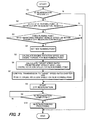
- FIG.3 is a flowchart describing a control routine relating to DPF regeneration executed by a controller.
- FIG.4 is a map showing the running range of the diesel engine in which DPF regeneration is possible in a continuously variable transmission (CVT), and defines the relation between engine rotation speed and engine torque for every vehicle speed.
- CVT continuously variable transmission
- FIG.6 is a map showing a post injection characteristic when engine rotation speed is fixed, and defines the relation between engine torque and fuel injection amount of the post injection.
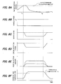
- FIG.7 is a time chart describing DPF regeneration control and its effect according to a first embodiment.
- FIG.7A shows a PM deposition amount as a function of time.
- FIG.7B shows vehicle speed as a function of time.
- FIG.7C shows speed ratio as a function of time.
- FIG.7D shows engine rotation speed as a function of time.
- FIG.7E shows post-injection amount as a function of time.
- FIG.7F shows exhaust gas temperature as a function of time.
- FIG.8 is a time chart describing DPF regeneration control and its effect according to a second embodiment.
- FIG.8A shows a PM deposition amount as a function of time.
- FIG.8B shows vehicle speed as a function of time.
- FIG.8C shows speed ratio as a function of time.
- FIG.8D shows engine rotation speed as a function of time.
- FIG.8E shows post-injection amount as a function of time.
- FIG.8F shows exhaust gas temperature as a function of time.
- FIG.10 is a time chart describing DPF regeneration control and its effect according to a third embodiment.
- FIG.10A shows a PM deposition amount as a function of time.
- FIG. 10B shows vehicle speed as a function of time.
- FIG.10C shows speed ratio as a function of time.
- FIG. 10D shows engine rotation speed as a function of time.
- FIG.10E shows post-injection amount as a function of time.
- FIG.10F shows exhaust gas temperature as a function of time.
- FIG. 11 is a shift map of a gear transmission.
- FIG. 12 is a diagram showing the running range of the diesel engine in which DPF regeneration is possible in the gear transmission, and defines the relation between engine rotation speed and engine torque for every vehicle speed.
- the diesel particulate filter purifies the exhaust gas from a vehicle diesel engine.
- a DPF11 is a filter which traps particulate matter (PM) in the exhaust gas discharged from the diesel engine 20, for example, a ceramic porous filter.
- the DPF11 is installed in the exhaust system for the diesel engine 20. If the DPF11 continues to trap the PM, it will become clogged. Once PM accumulates to some extent, the exhaust gas temperature is increased by controlling the fuel injection of the fuel injector 22. This burns and removes the deposited PM, and regenerates the DPF. The regeneration characteristics of the DPF11 are described later.
- the differential pressure sensor 12 is a pressure difference measurement means for detecting the differential pressure dP between the pressure on the inlet side and the outlet side of the DPF11. The amount of trapped PM is estimated from the magnitude of the differential pressure, and thus the differential pressure sensor 12 assists the controller 40 in determining the regeneration timing of the DPF.
- the differential pressure sensor 12 outputs the detected differential pressure signal to the controller 40.
- the differential pressure sensor 12 is an example of the condition detecting sensor which detects a condition of the DPF11. When the condition of the DPF11 becomes a predetermined condition, the controller 40 determines that regeneration of DPF 11 is required.
- the condition of the DPF11 means the differential pressure and the predetermined condition corresponds to an experimentally predetermined value of the differential pressure.
- the DPF inlet temperature sensor 13 is a temperature measurement means for detecting the inlet temperature Ti (i.e., the exhaust gas temperature of the diesel engine 20) of the DPF11, and outputs a signal indicative of the inlet temperature to the controller 40.
- a DPF outlet temperature sensor 14 is a temperature measurement means for detecting the outlet temperature To of the DPF11, and outputs an signal indicative of the outlet temperature to the controller 40.
- the vehicle speed sensor 27 is a vehicle speed ( Vsp ) measurement means, and may be a sensor which detects the rotation speed of the output shaft of the automatic transmission 30.
- the engine speed sensor 28 is an engine rotation speed ( Ne ) measurement means, and may be a sensor which detects the rotation speed of the output shaft of a diesel engine 20.
- the signals from the sensors 12-14 and 27-28 are inputted to the controller 40.
- the controller 40 functions as a running point determining means. When the controller 40 determines that regeneration of the DPF11 is required, it determines whether or not the running point of the diesel engine 20 is in a temperature region in which self-ignition of particulates is possible.
- "running point” is a set of engine rotation speed Ne and engine torque ETor (engine load) i.e., ( Ne, ETor ).
- Ne, ETor engine load
- the controller 40 sets a new running point while maintaining vehicle speed Vsp . Thus, it functions as a running point setting means of the diesel engine 20.
- the new running point is a running point at which hot exhaust gas can be discharged to raise the particulates to the self-ignition temperature, and the same vehicle speed is maintained at the new running point and the original running point.
- the controller 40 determines whether there is the new running point at which hot exhaust gas can be discharged to raise the particulates to self-ignition temperature.
- the controller 40 changes the speed ratio of the automatic transmission 30 so as to realize the set new running point.
- the controller 40 determines a target speed ratio based on the engine rotation speed corresponding to the new running point and the vehicle speed. In this way, the controller 40 further functions as a target speed ratio determination means.
- the controller 40 controls the automatic transmission 30 so that the target speed ratio is obtained.
- the controller 40 further functions as a speed ratio change means.
- the controller 40 controls a throttle valve 21 of the diesel engine 20, the fuel injector 22 of the diesel engine 20 and transmission 30, and changes the engine rotation speed.
- the controller 40 further controls the fuel injection timing and injection amount, and performs post-injection and injection timing retardation if required. The details of the control performed by the controller 40 will be described later.
- FIG.2 is a graph showing the regeneration characteristics of the DPF. Exhaust gas temperature is shown on the horizontal axis, and DPF regeneration rate is shown on the vertical axis. As shown in FIG.2, when the exhaust gas temperature Ti is a low temperature, the DPF cannot be regenerated, but when the exhaust gas temperature is higher than a threshold temperature Te , the PM bums and the DPF can be regenerated. The DPF regeneration rate also increases with the rise of exhaust gas temperature. For example, the threshold temperature Te is 400 degrees C.
- a step S1 the controller 40 determines whether or not regeneration of the DPF11 is required. If regeneration is required, the routine proceeds to a step S2. If regeneration is unnecessary, the routine is terminated.
- the need for regeneration of the DPF is determined from the magnitude of the differential pressure dP at the inlet and outlet of the DPF detected by the differential pressure sensor 12. When the differential pressure is larger than a predetermined value due to clogging of the DPF (i.e. when the PM deposition amount exceeds a predetermined PM deposition amount that requires the start of regeneration), it is determined that regeneration of DPF is required.
- the predetermined value or the predetermined PM deposition amount is experimentally determined depending on the construction of the DPF.
- step S2 it is determined whether or not the present running point of the diesel engine 20 is in a running range where regeneration of the DPF is difficult. This determination is performed by looking up the map of FIG.4.
- the map of FIG. 4 is stored in the ROM of the controller 40, and defines the relation between engine rotation speed and engine torque for every vehicle speed.
- FIG. 4 shows the running range in which DPF regeneration is possible within an engine rotation speed-engine torque plane. The engine rotation speed is shown on the horizontal axis, and engine torque (engine load) is shown on the vertical axis.
- the running range in which DPF regeneration is possible can be experimentally determined beforehand.
- the bold curves show isovalue curves for the vehicle speed Vsp. In other words, a constant vehicle speed can be maintained at all running points on each isovalue curve.
- the dot-and-dash curve shows the boundary 50 of the running range in which the exhaust gas temperature Ti can reach a temperature higher than the threshold temperature Te .
- the engine running range above the boundary 50 is referred to as "feasible DPF regeneration region" in this description.
- the exhaust gas temperature can rise to a temperature (higher than the threshold temperature Te) at which PM can burn by a suitable "post-injection” or suitable “injection timing retardation” which does not cause problems, such as fuel adhesion to the wall of the cylinder liner.
- the engine running range below the boundary 50 is an engine running range wherein even if "post-injection” and “injection timing retardation” are performed, DPF regeneration is difficult, because either PM cannot be burned or problems such as fuel adhesion to the wall of the cylinder liner arise.
- This range is referred to as "difficult DPF regeneration range” in this description.
- the running point A in FIG.4 is in the feasible DPF regeneration region, whereas the running points B and C are in the difficult DPF regeneration region.
- Step S2 it is determined whether or not the present running point is in the difficult DPF regeneration region by looking up the map of FIG.4.
- the present vehicle speed Vsp is read from the vehicle speed sensor 27 and the present engine rotation speed Ne is read from the engine speed sensor 28.
- the present engine torque Etor is obtained from the present vehicle speed Vsp and the present engine rotation speed Ne by looking up the map of FIG.4, whereby the present running point ( Ne , ETor ) of the diesel engine 20 is found. If the running point of the diesel engine 20 is not in the difficult DPF regeneration region (i.e., the running point is in the feasible DPF regeneration region), the routine proceeds to a Step S8, and if the running point of the diesel engine 20 is in the difficult DPF regeneration region, the routine proceeds to a Step S3.
- a step S3 the present vehicle speed is read by using the vehicle speed sensor 27, and then, referring to FIG.4, it is determined whether or not the isovalue curve which maintains the present vehicle speed, passes through the feasible DPF regeneration region.
- a running point is searched which maintains the present vehicle speed and is suitable for DPF regeneration.
- the routine proceeds to the Step S8.
- the routine proceeds to a Step S4 for changing running point.
- a step S4 the map of FIG.4 is looked up and a new running point maintaining the present vehicle speed is set.
- a modification of the running point is performed.
- the present running point is the point B in FIG. 4.
- the present running point B is changed and a new running point D is set.
- the new running point D is determined in consideration of both viewpoints.
- the running point D may be separated from the intersection of isovalue curve for the present speed and the boundary 50 by only a predetermined distance.
- step S5 the engine rotation speed NeD and engine torque TD for the new running point D are calculated from the map of FIG.4.
- a target speed ratio is calculated from a present vehicle speed V3 and engine rotation speed NeD for the new running point D. This may be calculated for example by looking up a shift map shown in FIG.5 stored in a ROM.
- the lines in FIG.5 show 1st-4th gear (Gr 1-4) of the manual mode of the CVT.
- the slope of the line on the Lo side (high speed ratio) is steep, and the slope of the line on the Hi side (low speed ratio) is gradual.
- the speed change of the CVT is performed by changing the ratio of the radii of the pair of pulleys.
- Step S6 the target speed ratio for the vehicle speed Vsp and the engine rotation speed NeD of the running point D are calculated based on the shift map of FIG.5.
- a command signal to decrease the speed ratio is sent to the automatic transmission 30 (CVT), and a command signal to lower the engine rotation speed is sent to the engine (throttle valve 21, fuel injector 22).
- the engine rotation speed NeD is realized and the speed ratio of the automatic transmission 30 is controlled to the target speed ratio.
- step S8 regeneration of the DPF is started.
- the map of FIG.6 is looked up and "post-injection" is performed.
- the post injection amount ID for the post injection is the fuel injection amount required for DPF regeneration. Since a large engine torque increases the exhaust gas temperature, the post injection amount ID decreases as the engine torque TD for the new running point D increases.
- the post injection amount ID relative to the engine torque TD found in the step S5 can be calculated using this map.
- post-injection is started by calculating the post-injection amount ID required for DPF regeneration based on the map of FIG.6.
- the effect of the control of this embodiment on the CVT will now be described referring to the time charts of FIG.7A-F.
- the solid line relates to the control of this embodiment, and the dashed line relates to the case where the control of this embodiment is not performed (where speed change control is not performed).
- the exhaust gas temperature may be increased to a temperature above the threshold temperature Te at which DPF regeneration is possible (FIG.7F), while maintaining a fixed vehicle speed (FIG.7B) and without changing the speed ratio or engine rotation speed (dashed lines of FIG.7C and D).
- the fuel injection amount of the post-injection must be sharply increased (dashed line of FIG.7E). If the post-injection amount is increased, fuel consumption will be impaired.
- the control of this embodiment can perform filter regeneration processing by changing the running point of the engine so that the exhaust gas temperature will be high, even when the engine load is small and the exhaust gas temperature is low.
- the injection amount of the "post-injection” can be reduced as compared with the prior art in which the running point of the engine is not changed. In this way, the control of this embodiment has the effect of improving fuel consumption.
- DPF regeneration processing is performed not by post-injection but by "injection timing retardation”.
- the controller 40 controls the fuel injector 22 to delay fuel injection timing.
- the retardation amount RD required for DPF regeneration is found by looking up the map of FIG.9 according to the engine torque TD calculated in the step S5.
- the map of FIG. 9 is stored in the ROM, and determines the relation between the retardation amount RD of the fuel injection timing, and the engine torque Etor .
- the retardation amount RD decreases as the engine torque TD for the new running point D increases.
- the retardation amount can be made small.
- this embodiment describes the DPF regeneration control for a gear transmission.
- the control routine is identical to that of FIG.3.
- PM is deposited with passing time.
- the control of the steps S2-S10 is started (time t1; Step S1).
- the speed ratio is shifted to the Hi side (solid line of FIG.10C; Step S7), and thus the engine rotation speed is reduced (FIG.10D; Step S7).
- a post-injection is performed at the speed ratio and engine rotation speed set in the steps S4-S7 (FIG.10E; Step S8).
- This control can raise the exhaust gas temperature to a temperature above the threshold temperature Te at which DPF regeneration can be started (FIG.10F).
- the exhaust gas temperature can be increased to a temperature higher than the DPF regeneration temperature Te without increasing the post-injection amount largely, and therefore, fuel cost-performance can be improved.
- post-injection and injection timing retardation are performed together with change of running point (change of engine rotation speed and speed ratio), post-injection and injection timing retardation are not necessary if the change of the running point enables the exhaust gas temperature to increase to a temperature higher than the DPF regeneration temperature Te by itself. Further, injection timing retardation may also be performed to raise the exhaust gas temperature in a gear transmission.
Abstract
Description
- This invention relates to regeneration of a diesel particulate filter for trapping particulate matter in exhaust gas.
- If a diesel particulate filter (hereafter, "DPF") continues to trap particulate matter (hereafter, "PM"), it will clog. Tokkai Hei 10-73018, published by the Japanese Patent Office in 1998, discloses a "post-injection" which is a second fuel injection after the usual fuel injection, and an "injection timing retardation" which is a delay of the fuel injection timing as a method of raising exhaust gas temperature for regeneration of the DPF. "Post-injection" and "injection timing retardation" raise exhaust gas temperature to the self-ignition temperature of the PM, and burn the PM which is deposited in the DPF.
- However, as the exhaust gas temperature is naturally low when engine power is low, it is difficult to raise exhaust gas temperature to the self-ignition temperature of the PM only by using "post-injection" or "injection timing retardation". Although the exhaust gas temperature can be increased by performing a "post-injection" with a large fuel injection amount, the increase in fuel injection amount causes poorer fuel consumption performance. As the increase in fuel injection amount increases engine torque, it is necessary to delay the "post-injection" timing. Due to the delay of the "post-injection" timing, fuel spray reaches the wall of the engine cylinder liner without being injected into the piston combustion chamber. As a result, fuel may adhere to the wall of the cylinder liner, and dilution of engine oil may occur.
- It is therefore an object of this invention to regenerate a filter without worsening fuel consumption or diluting engine oil.
- In order to achieve the above object, this invention provides a regeneration device for a diesel particulate filter which traps particulates in exhaust gas discharged from a vehicle diesel engine, wherein the diesel engine outputs an engine torque through an automatic transmission to drive wheels. The regeneration device comprises a condition detecting sensor which detects a condition of the diesel particulate filter and a controller. The controller stores a map defining a predetermined running region of a diesel engine in which self-ignition of trapped particulates is possible. The controller is programmed to determine whether or not regeneration of the filter is required based on the detected condition; modify a running point of the diesel engine to a point within the predetermined running region when the regeneration of the filter is required; set a target speed ratio of the automatic transmission based on an engine rotation speed at the modified running point; and control a speed ratio of the automatic transmission to the target speed ratio.
- This invention further provides a regeneration method for regenerating a diesel particulate filter which traps particulates in exhaust gas discharged from a vehicle diesel engine, wherein the diesel engine outputs an engine torque through an automatic transmission to drive wheels. The regeneration method comprises the steps of storing a map defining a predetermined running region of a diesel engine in which self-ignition of trapped particulates is possible; detecting a condition of the diesel particulate filter; determining whether or not regeneration of the filter is required based on the detected condition; modifying a running point of the diesel engine to a point within the predetermined running region when the regeneration of the filter is required; setting a target speed ratio of the automatic transmission based on an engine rotation speed at the modified running point; and controlling a speed ratio of the automatic transmission to the target speed ratio.
- The details as well as other features and advantages of this invention are set forth in the remainder of the specification and are shown in the accompanying drawings.
- FIG.1 is a schematic diagram of a vehicle provided with a diesel particulate filter and its regeneration device.
- FIG.2 is a graph showing the regeneration characteristics of the DPF and the regeneration rate of the DPF as a function of exhaust gas temperature.
- FIG.3 is a flowchart describing a control routine relating to DPF regeneration executed by a controller.
- FIG.4 is a map showing the running range of the diesel engine in which DPF regeneration is possible in a continuously variable transmission (CVT), and defines the relation between engine rotation speed and engine torque for every vehicle speed.
- FIG.5 is a shift map of a CVT.
- FIG.6 is a map showing a post injection characteristic when engine rotation speed is fixed, and defines the relation between engine torque and fuel injection amount of the post injection.
- FIG.7 is a time chart describing DPF regeneration control and its effect according to a first embodiment. FIG.7A shows a PM deposition amount as a function of time. FIG.7B shows vehicle speed as a function of time. FIG.7C shows speed ratio as a function of time. FIG.7D shows engine rotation speed as a function of time. FIG.7E shows post-injection amount as a function of time. FIG.7F shows exhaust gas temperature as a function of time.
- FIG.8 is a time chart describing DPF regeneration control and its effect according to a second embodiment. FIG.8A shows a PM deposition amount as a function of time. FIG.8B shows vehicle speed as a function of time. FIG.8C shows speed ratio as a function of time. FIG.8D shows engine rotation speed as a function of time. FIG.8E shows post-injection amount as a function of time. FIG.8F shows exhaust gas temperature as a function of time.
- FIG.9 is a map showing an injection timing retardation characteristic when engine rotation speed is fixed, and defines the relation between engine torque and a retardation amount.
- FIG.10 is a time chart describing DPF regeneration control and its effect according to a third embodiment. FIG.10A shows a PM deposition amount as a function of time. FIG. 10B shows vehicle speed as a function of time. FIG.10C shows speed ratio as a function of time. FIG. 10D shows engine rotation speed as a function of time. FIG.10E shows post-injection amount as a function of time. FIG.10F shows exhaust gas temperature as a function of time.
- FIG. 11 is a shift map of a gear transmission.
- FIG. 12 is a diagram showing the running range of the diesel engine in which DPF regeneration is possible in the gear transmission, and defines the relation between engine rotation speed and engine torque for every vehicle speed.
- Referring to FIG. 1, a regeneration device for a diesel particulate filter according to this invention will now be described. The diesel particulate filter purifies the exhaust gas from a vehicle diesel engine.
- A
DPF regeneration device 10 for reproducing a DPF11 is provided with acontroller 40,differential pressure sensor 12,vehicle speed sensor 27 that detects vehicle speed Vsp ,engine speed sensor 28 that detects engine rotation speed Ne of adiesel engine 20, and afuel injector 22 of thediesel engine 20. Thecontroller 40 controls thediesel engine 20 and anautomatic transmission 30, and thus varies the engine rotation speed and speed ratio. In this description, the speed ratio of theautomatic transmission 30 means a speed reduction ratio, i.e. (input speed)/(output speed). Theautomatic transmission 30 is connected to the output shaft of thediesel engine 20, and the engine torque outputted from thediesel engine 20 is inputted into theautomatic transmission 30. Theautomatic transmission 30 converts the engine torque from thediesel engine 20 into a drive torque, and the drive torque is transmitted to the drive wheels. The automatic transmission may be of the usual type, comprising a transmission mechanism comprising a torque converter, a planetary gear set and clutches, and control valves which change the path of the oil supplied to clutches. By controlling the control valves, thecontroller 40 changes over the clutch engaged to select a gear, and performs gear selection control. When the automatic transmission is a continuously variable transmission (CVT), the automatic transmission further comprises a pair of pulleys synchronized with a belt, and control valves which adjust the oil pressure supplied to the pulleys. A typical continuously variable transmission (CVT) is disclosed by U.S. Pat. No. 5,439,424 granted on August 8, 1995 to Sawada et al. - The
controller 40 controls the fuel injection timing of thefuel injector 22, and performs "post-injection" and "injection timing retardation" if required. A "post-injection" is another fuel injection following the usual main fuel injection, and it is performed additionally to the main fuel injection that is implemented at a point of time near the dead top center of the compression stroke of thediesel engine 20. Thus, thefuel injector 22 functions as an exhaust gas temperature adjustment mechanism which adjusts the exhaust gas temperature of thediesel engine 20. Thecontroller 40 is provided with a microcomputer including a central processing unit (CPU) which executes programs, a read-only memory (ROM) which stores programs and data, a random access memory (RAM) which temporarily stores the computation result of the CPU and acquired data, and an input-output interface (I/O interface). - A DPF11 is a filter which traps particulate matter (PM) in the exhaust gas discharged from the
diesel engine 20, for example, a ceramic porous filter. The DPF11 is installed in the exhaust system for thediesel engine 20. If the DPF11 continues to trap the PM, it will become clogged. Once PM accumulates to some extent, the exhaust gas temperature is increased by controlling the fuel injection of thefuel injector 22. This burns and removes the deposited PM, and regenerates the DPF. The regeneration characteristics of the DPF11 are described later. - The
differential pressure sensor 12 is a pressure difference measurement means for detecting the differential pressure dP between the pressure on the inlet side and the outlet side of the DPF11. The amount of trapped PM is estimated from the magnitude of the differential pressure, and thus thedifferential pressure sensor 12 assists thecontroller 40 in determining the regeneration timing of the DPF. Thedifferential pressure sensor 12 outputs the detected differential pressure signal to thecontroller 40. Thedifferential pressure sensor 12 is an example of the condition detecting sensor which detects a condition of the DPF11. When the condition of the DPF11 becomes a predetermined condition, thecontroller 40 determines that regeneration ofDPF 11 is required. For thedifferential pressure sensor 12, the condition of the DPF11 means the differential pressure and the predetermined condition corresponds to an experimentally predetermined value of the differential pressure. - The DPF
inlet temperature sensor 13 is a temperature measurement means for detecting the inlet temperature Ti (i.e., the exhaust gas temperature of the diesel engine 20) of the DPF11, and outputs a signal indicative of the inlet temperature to thecontroller 40. A DPFoutlet temperature sensor 14 is a temperature measurement means for detecting the outlet temperature To of the DPF11, and outputs an signal indicative of the outlet temperature to thecontroller 40. Thevehicle speed sensor 27 is a vehicle speed ( Vsp ) measurement means, and may be a sensor which detects the rotation speed of the output shaft of theautomatic transmission 30. Theengine speed sensor 28 is an engine rotation speed ( Ne ) measurement means, and may be a sensor which detects the rotation speed of the output shaft of adiesel engine 20. The signals from the sensors 12-14 and 27-28 are inputted to thecontroller 40. - The
controller 40 functions as a running point determining means. When thecontroller 40 determines that regeneration of the DPF11 is required, it determines whether or not the running point of thediesel engine 20 is in a temperature region in which self-ignition of particulates is possible. Here, "running point" is a set of engine rotation speed Ne and engine torque ETor (engine load) i.e., ( Ne, ETor ). When the running point of thediesel engine 20 is not in the region in which self-ignition of particulates is possible, thecontroller 40 sets a new running point while maintaining vehicle speed Vsp . Thus, it functions as a running point setting means of thediesel engine 20. The new running point is a running point at which hot exhaust gas can be discharged to raise the particulates to the self-ignition temperature, and the same vehicle speed is maintained at the new running point and the original running point. Thecontroller 40 determines whether there is the new running point at which hot exhaust gas can be discharged to raise the particulates to self-ignition temperature. - When such a new running point exists, the
controller 40 changes the speed ratio of theautomatic transmission 30 so as to realize the set new running point. In other words, when it is determined that DPF regeneration is required, thecontroller 40 determines a target speed ratio based on the engine rotation speed corresponding to the new running point and the vehicle speed. In this way, thecontroller 40 further functions as a target speed ratio determination means. Thecontroller 40 controls theautomatic transmission 30 so that the target speed ratio is obtained. Thus, thecontroller 40 further functions as a speed ratio change means. - In order to attain the engine rotation speed corresponding to the new running point, the
controller 40 controls athrottle valve 21 of thediesel engine 20, thefuel injector 22 of thediesel engine 20 andtransmission 30, and changes the engine rotation speed. Thecontroller 40 further controls the fuel injection timing and injection amount, and performs post-injection and injection timing retardation if required. The details of the control performed by thecontroller 40 will be described later. - FIG.2 is a graph showing the regeneration characteristics of the DPF. Exhaust gas temperature is shown on the horizontal axis, and DPF regeneration rate is shown on the vertical axis. As shown in FIG.2, when the exhaust gas temperature Ti is a low temperature, the DPF cannot be regenerated, but when the exhaust gas temperature is higher than a threshold temperature Te , the PM bums and the DPF can be regenerated. The DPF regeneration rate also increases with the rise of exhaust gas temperature. For example, the threshold temperature Te is 400 degrees C.
- Referring to FIG. 3-7, a first embodiment of regeneration control of the particulate filter will be described. In the first embodiment, the
automatic transmission 30 is a continuously variable transmission (CVT). The control routine shown in the flowchart of FIG. 3 is implemented as a program executed by thecontroller 40. The control routine is basically repeatedly performed by interrupt processing every 10 milliseconds. However, interrupt is forbidden until the control routine is completed. - In a step S1, the
controller 40 determines whether or not regeneration of the DPF11 is required. If regeneration is required, the routine proceeds to a step S2. If regeneration is unnecessary, the routine is terminated. The need for regeneration of the DPF is determined from the magnitude of the differential pressure dP at the inlet and outlet of the DPF detected by thedifferential pressure sensor 12. When the differential pressure is larger than a predetermined value due to clogging of the DPF (i.e. when the PM deposition amount exceeds a predetermined PM deposition amount that requires the start of regeneration), it is determined that regeneration of DPF is required. The predetermined value or the predetermined PM deposition amount is experimentally determined depending on the construction of the DPF. - In the step S2, it is determined whether or not the present running point of the
diesel engine 20 is in a running range where regeneration of the DPF is difficult. This determination is performed by looking up the map of FIG.4. The map of FIG. 4 is stored in the ROM of thecontroller 40, and defines the relation between engine rotation speed and engine torque for every vehicle speed. FIG. 4 shows the running range in which DPF regeneration is possible within an engine rotation speed-engine torque plane. The engine rotation speed is shown on the horizontal axis, and engine torque (engine load) is shown on the vertical axis. The running range in which DPF regeneration is possible can be experimentally determined beforehand. The bold curves show isovalue curves for the vehicle speed Vsp. In other words, a constant vehicle speed can be maintained at all running points on each isovalue curve. In FIG.4, exemplary isovalue curves ( Vsp =V1, Vsp =V2, Vsp =V3, Vsp =V4) are shown, and here the vehicle speed increases towards the upper side of paper, namely V4>V3>V2>V1. - In FIG.4, the dot-and-dash curve shows the
boundary 50 of the running range in which the exhaust gas temperature Ti can reach a temperature higher than the threshold temperature Te . The engine running range above theboundary 50 is referred to as "feasible DPF regeneration region" in this description. In this engine running range, the exhaust gas temperature can rise to a temperature (higher than the threshold temperature Te) at which PM can burn by a suitable "post-injection" or suitable "injection timing retardation" which does not cause problems, such as fuel adhesion to the wall of the cylinder liner. The engine running range below theboundary 50 is an engine running range wherein even if "post-injection" and "injection timing retardation" are performed, DPF regeneration is difficult, because either PM cannot be burned or problems such as fuel adhesion to the wall of the cylinder liner arise. This range is referred to as "difficult DPF regeneration range" in this description. For example, the running point A in FIG.4 is in the feasible DPF regeneration region, whereas the running points B and C are in the difficult DPF regeneration region. - The thin solid line is an isothermal curve for exhaust gas temperature. Specifically, using the isothermal exhaust gas temperature curve, the exhaust gas temperature is obtained from the engine rotation speed and engine torque. Upper curves show high temperatures and lower curves show low temperatures. In Fig. 4, the curve with a mountain-like shape is a maximum torque curve.
- In a Step S2, it is determined whether or not the present running point is in the difficult DPF regeneration region by looking up the map of FIG.4. The present vehicle speed Vsp is read from the
vehicle speed sensor 27 and the present engine rotation speed Ne is read from theengine speed sensor 28. The present engine torque Etor is obtained from the present vehicle speed Vsp and the present engine rotation speed Ne by looking up the map of FIG.4, whereby the present running point ( Ne, ETor ) of thediesel engine 20 is found. If the running point of thediesel engine 20 is not in the difficult DPF regeneration region (i.e., the running point is in the feasible DPF regeneration region), the routine proceeds to a Step S8, and if the running point of thediesel engine 20 is in the difficult DPF regeneration region, the routine proceeds to a Step S3. - In a step S3, the present vehicle speed is read by using the
vehicle speed sensor 27, and then, referring to FIG.4, it is determined whether or not the isovalue curve which maintains the present vehicle speed, passes through the feasible DPF regeneration region. Thus, a running point is searched which maintains the present vehicle speed and is suitable for DPF regeneration. For example, in the map of FIG.4, although the running point B is not a suitable running point for DPF regeneration, as the isovalue curve (Vsp=V3) passes through the feasible DPF regeneration region, a suitable running point (e.g. point D) for DPF regeneration exists. In the map of FIG.4, the running point C is not a suitable running point for DPF regeneration, and the isovalue curve (Vsp=V1) does not pass through the feasible DPF regeneration region. As a running point suitable for DPF regeneration does not exist when the isovalue curve for the present speed does not pass through the feasible DPF regeneration region, the routine proceeds to the Step S8. On the other hand, when the feasible DPF regeneration region includes the isovalue curve for the present speed, the routine proceeds to a Step S4 for changing running point. - In a step S4, the map of FIG.4 is looked up and a new running point maintaining the present vehicle speed is set. Thus, a modification of the running point is performed. Hereafter, it is assumed that the present running point is the point B in FIG. 4. The present running point B is changed and a new running point D is set. From the viewpoint of preventing rapid change of engine rotation speed or engine torque, it is desirable to position the new running point D at the intersection of the isovalue curve for the present speed and the
boundary 50. On the other hand, from the viewpoint of performing satisfactory DPF regeneration, it is desirable to position the new running point D away from theboundary 50. Therefore, the running point D is determined in consideration of both viewpoints. For example, the running point D may be separated from the intersection of isovalue curve for the present speed and theboundary 50 by only a predetermined distance. - In a step S5, the engine rotation speed NeD and engine torque TD for the new running point D are calculated from the map of FIG.4.
- In a step S6, a target speed ratio is calculated from a present vehicle speed V3 and engine rotation speed NeD for the new running point D. This may be calculated for example by looking up a shift map shown in FIG.5 stored in a ROM. The lines in FIG.5 show 1st-4th gear (Gr 1-4) of the manual mode of the CVT. The slope of the line on the Lo side (high speed ratio) is steep, and the slope of the line on the Hi side (low speed ratio) is gradual. The speed change of the CVT is performed by changing the ratio of the radii of the pair of pulleys.
- In the Step S6, the target speed ratio for the vehicle speed Vsp and the engine rotation speed NeD of the running point D are calculated based on the shift map of FIG.5.
- In a step S7, a command signal to decrease the speed ratio (upshift) is sent to the automatic transmission 30 (CVT), and a command signal to lower the engine rotation speed is sent to the engine (
throttle valve 21, fuel injector 22). In this way, the engine rotation speed NeD is realized and the speed ratio of theautomatic transmission 30 is controlled to the target speed ratio. - In a step S8, regeneration of the DPF is started. In this embodiment, in order to raise the temperature of the DPF, the map of FIG.6 is looked up and "post-injection" is performed.
- The map of FIG. 6 is stored in the ROM, and defines the relation of the post injection amount ID and the engine torque under the condition that the engine rotation speed Ne is constant (in this embodiment, Ne =NeD). The post injection amount ID for the post injection is the fuel injection amount required for DPF regeneration. Since a large engine torque increases the exhaust gas temperature, the post injection amount ID decreases as the engine torque TD for the new running point D increases. The post injection amount ID relative to the engine torque TD found in the step S5, can be calculated using this map. In the step S8, post-injection is started by calculating the post-injection amount ID required for DPF regeneration based on the map of FIG.6.
- In a step S9, it is determined whether or not regeneration of the DPF has been completed. For this determination a known method may be used, for example the determination may be performed according to the differential pressure at the inlet and outlet of the DPF or the elapsed time from regeneration start. It may be determined that regeneration of the DPF has been completed when the differential pressure is less than a second predetermined value or when the elapsed time from regeneration start is greater than a predetermined time.
- In a step S10, DPF regeneration end processing is performed. Specifically, post-injection is stopped. If a change of the speed ratio and the engine running point of steps S4-S7 is performed, the speed ratio is returned from the newly set speed ratio for the running point D to the original speed ratio before being changed by the steps S4-S7 (speed ratio for the running point B) and further the engine running point is returned from the running point D to the original running point B before being changed by the steps S4-S7.
- The effect of the control of this embodiment on the CVT will now be described referring to the time charts of FIG.7A-F. The solid line relates to the control of this embodiment, and the dashed line relates to the case where the control of this embodiment is not performed (where speed change control is not performed).
- As shown in FIG.7A, particulate matter (PM) is deposited with elapsed time. When the PM deposition amount exceeds a certain PM deposition amount that requires the start of regeneration, the aforesaid control is started (time t1; Step S1). When the vehicle speed is maintained constant (FIG.7B), the
transmission 30 is shifted to the Hi (low speed ratio) side so that the DPF can be regenerated (FIG.7C; Step S7). The engine rotation speed is reduced (FIG.7D; Step S7) by the upshift of thetransmission 30. Post-injection is started (FIG.7E; Step S8). Thus, by performing this control, the exhaust gas temperature rises to the threshold temperature Te at which DPF regeneration is possible (FIG.7 F). - When there is no further deposition of PM (time t2 in FIG.7A; Step S9), DPF regeneration processing is completed. The speed ratio (FIG.7C) and engine rotation speed (FIG.7D) are returned to their original values, post-injection is stopped (FIG.7E), and the exhaust gas temperature is returned to its original value, i.e. the temperature immediately before the regeneration started (FIG.7F).
- Then, PM is gradually deposited again (FIG.7A), and when the PM amount exceeds the PM deposition amount at regeneration start, the above regeneration processing is performed again.
- On the other hand, in the prior art, the exhaust gas temperature may be increased to a temperature above the threshold temperature Te at which DPF regeneration is possible (FIG.7F), while maintaining a fixed vehicle speed (FIG.7B) and without changing the speed ratio or engine rotation speed (dashed lines of FIG.7C and D). For this reason, the fuel injection amount of the post-injection must be sharply increased (dashed line of FIG.7E). If the post-injection amount is increased, fuel consumption will be impaired.
- The control of this embodiment can perform filter regeneration processing by changing the running point of the engine so that the exhaust gas temperature will be high, even when the engine load is small and the exhaust gas temperature is low. In the control of this embodiment, even when performing a "post-injection" to increase the exhaust gas temperature above the threshold temperature Te in addition to change-over of the running point of the engine, the injection amount of the "post-injection" can be reduced as compared with the prior art in which the running point of the engine is not changed. In this way, the control of this embodiment has the effect of improving fuel consumption.
- A second embodiment of the regeneration control of the particulate filter will now be described referring to FIG.8 and FIG.9. Identical symbols are assigned to parts having the same function as those of the first embodiment described above, and their description will not be repeated. The flowchart of regeneration control is the same as the flowchart of FIG.3.
- In this embodiment, in the Step S8 of the flowchart, DPF regeneration processing is performed not by post-injection but by "injection timing retardation". The
controller 40 controls thefuel injector 22 to delay fuel injection timing. The retardation amount RD required for DPF regeneration is found by looking up the map of FIG.9 according to the engine torque TD calculated in the step S5. The map of FIG. 9 is stored in the ROM, and determines the relation between the retardation amount RD of the fuel injection timing, and the engine torque Etor . The retardation amount RD decreases as the engine torque TD for the new running point D increases. - As a misfire will occur if the fuel injection timing is delayed too much (when the retardation amount is too large), there is an upper limiting value of the retardation amount. Therefore, for example, if the engine torque is TD1, and the retardation amount RD1 corresponding to the engine torque TD1 exceeds the upper limit, injection timing retardation is started after decreasing the engine torque from
TD 1 to TD2 and decreasing the retardation amount fromRD 1 to RD2. - Thus, even if the injection timing retardation is adjusted to perform DPF regeneration processing, as shown in FIG.8E, as compared with the prior art (dashed line) in which the speed ratio of the
transmission 30 and the running point of thediesel engine 20 are not modified, the retardation amount can be made small. - In this embodiment, in addition to the effect of the first embodiment, there is the additional effect that control is simple. Likewise, even when the fuel injection timing is retarded instead of performing a post-injection to raise the exhaust gas temperature to a temperature higher than the threshold temperature Te , as compared with the prior art wherein the running point of the engine is not changed, the retardation amount of the injection timing can be made small. Thus, the control of this embodiment has the effect of improving fuel consumption.
- A third embodiment of the regeneration control of the particulate filter will now be described, referring to FIG. 10-12.
- Although the first embodiment described the DPF regeneration control for a continuously variable transmission, this embodiment describes the DPF regeneration control for a gear transmission. The control routine is identical to that of FIG.3.
- As shown in FIG.10A, PM is deposited with passing time. When the PM deposition amount exceeds a predetermined PM deposition amount that requires the start of regeneration, the control of the steps S2-S10 is started (time t1; Step S1). While the vehicle speed is fixed (FIG. 10B), the speed ratio is shifted to the Hi side (solid line of FIG.10C; Step S7), and thus the engine rotation speed is reduced (FIG.10D; Step S7).
- The speed ratio and engine rotation speed are determined by looking up the shift map of FIG.11. The shift map for a gear transmission is stored in a ROM, and the lines shows 1st gear (i(1))-4th gear(i(4)). The slope of the line on the Lo (high speed ratio) side is steep, and the slope of the line on the Hi (low speed ratio) side is gradual.
- For a given vehicle speed, the running point can be selected from a maximum of four points. For example, in the case of a vehicle speed V3, it can be selected from the running point B1 of 1st gear (engine rotation speed NeB1), running point B2 of 2nd gear (engine rotation speed NeB2), running point B of 3rd gear (engine rotation speed NeB), and running point D of 4th gear (engine rotation speed NeD). These running points are plotted on the map of FIG. 12.
- FIG.12 shows the engine running range in which DPF regeneration is possible within an engine rotation speed-engine torque plane in a gear transmission. The horizontal axis shows the engine rotation speed Ne , and the vertical axis shows the engine torque Etor (engine load). For a given vehicle speed, the running point can be selected from a maximum of four points. For example, at the vehicle speed V3, the running point can be selected from four running points B 1 (not shown in the diagram), B2, B and D.
- For example, when DPF regeneration is required while the vehicle is running at the vehicle speed V3 with the engine at the running point B (3rd gear), the engine running point is changed from the running point B (3rd gear) to the running point D (4th gear). For example, when DPF regeneration is required while the vehicle is running at the vehicle speed V3 with the engine at the running point B2 (2nd gear), the engine running point is changed from the running point B2 (2nd gear) to the running point D (4th gear). This is because the running point B of 3rd gear or the running point B2 of 2rd gear is in the difficult DPF regeneration region, and in order to run the engine at the running point D in the feasible DPF regeneration region, the gear of the
transmission 30 is shifted up from 2nd gear to 4th gear. - Returning again to FIG.10, a post-injection is performed at the speed ratio and engine rotation speed set in the steps S4-S7 (FIG.10E; Step S8). This control can raise the exhaust gas temperature to a temperature above the threshold temperature Te at which DPF regeneration can be started (FIG.10F).
- When there is no PM deposition, (time t2 of FIG.10A; Step S10), DPF regeneration processing is terminated. The speed ratio (FIG.10C) and engine rotation speed (FIG.10D) are returned to the original speed ratio (FIG.10C) and the original engine rotation speed before being changed by the steps S4-S7. The post-injection stops (FIG.10E), and the exhaust gas temperature is returned to the original exhaust gas temperature before being changed by the steps S8-S9.
- Subsequently, as PM is gradually deposited again (FIG.10A), when it exceeds the predetermined PM deposition amount required to start regeneration, the above-mentioned control is repeated.
- On the other hand, to raise the exhaust gas temperature to a temperature higher than the threshold temperature Te at which the DPF can be regenerated (FIG.10F) without changing the engine rotation speed (dotted lines of FIG. 10 C and D) while maintaining a fixed vehicle speed (FIG.10B), the engine post-injection amount must be sharply increased (dashed line of FIG.10E). Thus, if the post-injection amount is increased, fuel consumption will be impaired.
- Therefore, by performing the control in this embodiment also in a gear transmission, the exhaust gas temperature can be increased to a temperature higher than the DPF regeneration temperature Te without increasing the post-injection amount largely, and therefore, fuel cost-performance can be improved.
- Although the invention has been described above by reference to certain embodiments of the invention, the invention is not limited to the embodiments described above. Although in the aforesaid three embodiments, post-injection and injection timing retardation are performed together with change of running point (change of engine rotation speed and speed ratio), post-injection and injection timing retardation are not necessary if the change of the running point enables the exhaust gas temperature to increase to a temperature higher than the DPF regeneration temperature Te by itself. Further, injection timing retardation may also be performed to raise the exhaust gas temperature in a gear transmission.
- Modifications and variations of the embodiment described above will occur to those skilled in the art, in light of the above teachings. The scope of the invention is defined with reference to the following claims.
- The entire contents of Japanese Patent Application P2003-1347 (filed January 7, 2003) are incorporated herein by reference.
Claims (12)
- A regeneration device for a diesel particulate filter (11) which traps particulates in exhaust gas discharged from a vehicle diesel engine (20), wherein the diesel engine (20) outputs an engine torque through an automatic transmission (30) to drive wheels; the regeneration device comprising:a condition detecting sensor (12) which detects a condition of the diesel particulate filter (11); anda controller (40) which stores a map defining a predetermined running region of a diesel engine (20) in which self-ignition of trapped particulates is possible, the controller being programmed to:determine whether or not regeneration of the filter (11) is required based on the detected condition;modify a running point of the diesel engine (20) to a point within the predetermined running region when the regeneration of the filter (11) is required;set a target speed ratio of the automatic transmission (30) based on an engine rotation speed at the modified running point; andcontrol a speed ratio of the automatic transmission (30) to the target speed ratio.
- The regeneration device as defined in Claim 1, further comprising a vehicle speed sensor (27) which detects a vehicle speed, and
wherein the controller (40) is programmed to read the vehicle speed from the vehicle speed sensor (27); modify the running point of the diesel engine (20) to a point which lies within the predetermined running region and which maintains the vehicle speed; and set the target speed ratio of the automatic transmission (30) based on the read vehicle speed and the engine rotation speed at the modified running point. - The regeneration device as defined in Claim 1 or Claim 2, wherein the controller (40) is programmed to control the automatic transmission (30) to the target speed ratio by performing an upshift of the automatic transmission (30).
- The regeneration device as defined in any one of Claim 1 to Claim 3, wherein the controller (40) is further programmed to determine whether or not the regeneration of the filter (11) is complete, and when the regeneration of the filter is complete, return the running point of the diesel engine (20) to a running point prior to the modification.
- The regeneration device as defined in any one of Claim 1 to Claim 4, wherein a running point prior to the modification lies outside the predetermined running region.
- The regeneration device as defined in any one of Claim 1 to Claim 5, further comprising a fuel injector (22) of the diesel engine (20),
wherein the controller (40) is further programmed to control the fuel injector (22) to perform a post-injection after controlling the speed ratio of the automatic transmission (30) to the target speed ratio, wherein the post-injection is another fuel injection following an ordinary fuel injection. - The regeneration device as defined in any one of Claim 1 to Claim 5, further comprising a fuel injector (22) of a diesel engine (20),
wherein the controller (40) is further programmed to control the fuel injector (22) to delay injection timing after controlling the speed ratio of the automatic transmission (30) to the target speed ratio. - The regeneration device as defined in any one of Claim 1 to Claim 7, wherein the condition detecting sensor (12) is a differential pressure sensor which detects a differential pressure between an inlet pressure and an outlet pressure of the filter; and
wherein the controller (40) is further programmed to determine that regeneration of the filter (11) is required when the differential pressure is larger than a predetermined value. - A regeneration device for a diesel particulate filter (11) which traps particulates in exhaust gas discharged from a vehicle diesel engine (20), wherein the diesel engine (20) outputs an engine torque through an automatic transmission (30) to drive wheels; the regeneration device comprising:means for storing a map defining a predetermined running region of a diesel engine (20) in which self-ignition of trapped particulates is possible;means for detecting a condition of the diesel particulate filter (11);means for determining whether or not regeneration of the filter (11) is required based on the condition of the filter;means for modifying a running point of the diesel engine (20) to a point within the predetermined running region when the regeneration of the filter (11) is required;means for setting a target speed ratio of the automatic transmission (30) based on an engine rotation speed at the modified running point; andmeans for controlling a speed ratio of the automatic transmission (30) to the target speed ratio.
- The regeneration device as defined in Claim 9, further comprising means for detecting a vehicle speed,
wherein said means for modifying a running point comprises means for modifying the running point of the diesel engine (20) to a point which lies within the predetermined running region and which maintains the vehicle speed,
and wherein said means for setting a target speed ratio comprises means for setting a target speed ratio of the automatic transmission (30) based on the detected vehicle speed and the engine rotation speed at the modified running point. - A regeneration method for regenerating a diesel particulate filter (11) which traps particulates in exhaust gas discharged from a vehicle diesel engine (20), wherein the diesel engine (20) outputs an engine torque through an automatic transmission (30) to drive wheels; the regeneration method comprising the steps of:storing a map defining a predetermined running region of a diesel engine (20) in which self-ignition of trapped particulates is possible;detecting a condition of the diesel particulate filter (11);determining whether or not regeneration of the filter (11) is required based on the detected condition;modifying a running point of the diesel engine (20) to a point within the predetermined running region when the regeneration of the filter (11) is required;setting a target speed ratio of the automatic transmission (30) based on an engine rotation speed at the modified running point; andcontrolling a speed ratio of the automatic transmission (30) to the target speed ratio.
- The regeneration device as defined in Claim 11, further comprising a step of detecting a vehicle speed,
wherein said step of modifying a running point comprises modifying the running point of the diesel engine (20) to a point which lies within the predetermined running region and which maintains the vehicle speed,
and wherein said step of setting a target speed ratio comprises setting a target speed ratio of the automatic transmission (30) based on the detected vehicle speed and the engine rotation speed at the modified running point.
Applications Claiming Priority (2)
| Application Number | Priority Date | Filing Date | Title |
|---|---|---|---|
| JP2003001347 | 2003-01-07 | ||
| JP2003001347A JP2004211638A (en) | 2003-01-07 | 2003-01-07 | Filter regeneration control system of diesel engine |
Publications (2)
| Publication Number | Publication Date |
|---|---|
| EP1437492A1 true EP1437492A1 (en) | 2004-07-14 |
| EP1437492B1 EP1437492B1 (en) | 2006-03-29 |
Family
ID=32501195
Family Applications (1)
| Application Number | Title | Priority Date | Filing Date |
|---|---|---|---|
| EP04000076A Expired - Fee Related EP1437492B1 (en) | 2003-01-07 | 2004-01-05 | Regeneration of diesel particulate filter |
Country Status (5)
| Country | Link |
|---|---|
| US (1) | US6971970B2 (en) |
| EP (1) | EP1437492B1 (en) |
| JP (1) | JP2004211638A (en) |
| CN (1) | CN1517520A (en) |
| DE (1) | DE602004000534T2 (en) |
Cited By (18)
| Publication number | Priority date | Publication date | Assignee | Title |
|---|---|---|---|---|
| EP1548257A2 (en) * | 2003-12-19 | 2005-06-29 | Nissan Motor Co., Ltd. | A regeneration system and method for a diesel particle filter |
| EP1617059A1 (en) * | 2004-07-16 | 2006-01-18 | Toyota Jidosha Kabushiki Kaisha | A particle filter regenration system which compensates for oil burnt in the combustion chamber |
| EP1722082A3 (en) * | 2005-05-13 | 2007-01-03 | HONDA MOTOR CO., Ltd. | Exhaust emission control system for internal combustion engine and control method therefor |
| FR2890926A1 (en) * | 2005-09-21 | 2007-03-23 | Renault Sas | METHOD FOR OBTAINING EXHAUST GASES FUEL-LOADED |
| WO2007042888A1 (en) * | 2005-10-07 | 2007-04-19 | Eaton Corporation | Narrow speed range diesel-powered engine system with aftertreatment devices |
| EP1785605A3 (en) * | 2005-11-11 | 2007-05-30 | Volkswagen Aktiengesellschaft | Method for the regeneration of a diesel particulate filter and corresponding transmission control |
| GB2437627A (en) * | 2006-04-27 | 2007-10-31 | Ford Global Tech Llc | A method of regenerating an emission control device |
| FR2901307A1 (en) * | 2006-05-16 | 2007-11-23 | Renault Sas | Diesel type internal combustion engine for motor vehicle, has fuel injection control system progressively modulating quantity of fuel injected during regeneration phase, from measured temperature threshold till measured temperature |
| WO2007145553A1 (en) | 2006-06-14 | 2007-12-21 | Volvo Lastvagnar Ab | Method and system for regenerating an exhaust gas purification unit. |
| WO2008100284A2 (en) * | 2006-09-29 | 2008-08-21 | Caterpillar Inc. | Power system |
| EP2066893A1 (en) * | 2006-09-15 | 2009-06-10 | Volvo Lastvagnar AB | Limiting transmission function while in regeneration mode for a diesel particulate filter |
| EP1939434A3 (en) * | 2006-12-27 | 2010-06-02 | Toyota Jidosha Kabushiki Kaisha | Apparatus and method for cleaning a particulate filter |
| CN101988435A (en) * | 2009-07-31 | 2011-03-23 | 福特环球技术公司 | Ontrolling regeneration of an emission control device |
| US8505281B2 (en) | 2009-09-30 | 2013-08-13 | Cummins Inc. | Techniques for enhancing aftertreatment regeneration capability |
| US9027327B2 (en) | 2006-06-14 | 2015-05-12 | Volvo Lasivagnar AB | Method and system for regenerating an exhaust gas purification unit |
| EP2905462A3 (en) * | 2013-12-21 | 2015-11-18 | Andersen, Peter | Method for start-up of a combustion engine of a generator set of an electric energy distribution system on board a ship |
| EP2617616A4 (en) * | 2010-09-16 | 2018-05-02 | Yanmar Co., Ltd. | Driving system controller of working vehicle |
| DE102016216062B4 (en) | 2015-08-31 | 2022-04-14 | Ford Global Technologies, Llc | Optimized LNT diagnostics |
Families Citing this family (34)
| Publication number | Priority date | Publication date | Assignee | Title |
|---|---|---|---|---|
| JP4148178B2 (en) * | 2004-04-08 | 2008-09-10 | いすゞ自動車株式会社 | Exhaust gas purification system control method and exhaust gas purification system |
| JP4810922B2 (en) * | 2004-08-10 | 2011-11-09 | 日産自動車株式会社 | PM deposition amount estimation controller |
| JP2006283709A (en) | 2005-04-01 | 2006-10-19 | Toyota Motor Corp | Control device for internal combustion engine |
| US7406822B2 (en) * | 2005-06-30 | 2008-08-05 | Caterpillar Inc. | Particulate trap regeneration system and control strategy |
| US20070079605A1 (en) * | 2005-10-07 | 2007-04-12 | Eaton Corporation | Exhaust aftertreatment system with transmission control |
| US7628009B2 (en) * | 2005-10-07 | 2009-12-08 | Eaton Corporation | Exhaust aftertreatment system with transmission control |
| JP4428361B2 (en) * | 2006-05-24 | 2010-03-10 | トヨタ自動車株式会社 | Exhaust gas purification system for internal combustion engine |
| JP4905303B2 (en) * | 2006-10-02 | 2012-03-28 | 日産自動車株式会社 | Method and apparatus for controlling exhaust gas temperature of internal combustion engine and internal combustion engine system |
| DE102006053104B4 (en) * | 2006-11-10 | 2019-10-31 | Robert Bosch Gmbh | Method for adapting a map |
| JP4750062B2 (en) * | 2007-03-06 | 2011-08-17 | ヤンマー株式会社 | Diesel engine control method |
| JP4665924B2 (en) * | 2007-03-16 | 2011-04-06 | トヨタ自動車株式会社 | Exhaust gas purification system for internal combustion engine |
| DE102007033678B4 (en) * | 2007-07-19 | 2022-08-11 | Robert Bosch Gmbh | Method and device for controlling an internal combustion engine |
| US8042325B2 (en) * | 2007-11-01 | 2011-10-25 | Ford Global Technologies, Llc | Adapting indicated engine torque during regeneration of a diesel particulate filter |
| US8277363B2 (en) * | 2007-11-07 | 2012-10-02 | GM Global Technology Operations LLC | Method and apparatus to control temperature of an exhaust aftertreatment system for a hybrid powertrain |
| DE102008058010B4 (en) * | 2008-11-19 | 2015-03-12 | Continental Automotive Gmbh | Method and device for operating an internal combustion engine |
| JP5215940B2 (en) * | 2009-05-28 | 2013-06-19 | 富士重工業株式会社 | Coordinated control device for engine and continuously variable transmission |
| US8615989B2 (en) | 2010-01-25 | 2013-12-31 | Deere & Company | Method for regeneration of diesel particulate filter in an exhaust aftertreatment system of an IC engine |
| JPWO2011093400A1 (en) * | 2010-01-28 | 2013-06-06 | 日立建機株式会社 | Exhaust gas purification system for hydraulic work machines |
| US8959898B2 (en) * | 2011-04-26 | 2015-02-24 | GM Global Technology Operations LLC | Regeneration methods and systems for particulate filters |
| JP5843154B2 (en) * | 2012-01-10 | 2016-01-13 | 三菱ふそうトラック・バス株式会社 | Exhaust gas purification apparatus and control method thereof |
| SE539218C2 (en) | 2012-10-02 | 2017-05-16 | Scania Cv Ab | Control of a temperature in an exhaust system |
| US9657667B2 (en) | 2012-10-02 | 2017-05-23 | Scania Cv Ab | Regulation of a temperature in an exhaust aftertreatment system |
| JP6217398B2 (en) * | 2014-01-09 | 2017-10-25 | マツダ株式会社 | Fuel injection control device for diesel engine |
| US10487715B2 (en) * | 2015-08-20 | 2019-11-26 | Ford Global Technologies, Llc | Regeneration of particulate filters in autonomously controllable vehicles |
| JP6568485B2 (en) * | 2016-02-04 | 2019-08-28 | 本田技研工業株式会社 | Control device for internal combustion engine |
| US10344657B2 (en) | 2016-02-12 | 2019-07-09 | GM Global Technology Operations LLC | System and method for particulate filter regeneration |
| CN106150718B (en) * | 2016-08-31 | 2019-07-05 | 潍柴动力股份有限公司 | A kind of engine gears optimization method and device |
| JP6673271B2 (en) * | 2017-03-22 | 2020-03-25 | トヨタ自動車株式会社 | Car |
| WO2019001721A1 (en) | 2017-06-29 | 2019-01-03 | Volvo Truck Corporation | Method for controlling a vehicle propulsion system |
| CN107120198B (en) * | 2017-07-12 | 2023-11-28 | 恒天九五重工有限公司 | Engine emission control device and method for hydraulic engineering machinery |
| CN111173595B (en) * | 2020-01-19 | 2021-02-09 | 中国第一汽车股份有限公司 | Particle trapping device regeneration system and control method thereof |
| CN114909462A (en) * | 2022-05-09 | 2022-08-16 | 潍柴动力股份有限公司 | Automatic transmission shift control method, device, storage medium and program product |
| CN114810384B (en) * | 2022-05-10 | 2023-05-23 | 潍柴动力股份有限公司 | Method and device for controlling post-treatment inlet temperature |
| CN115324757B (en) * | 2022-09-05 | 2023-11-17 | 潍柴动力股份有限公司 | Control method, control device and electronic control unit for DPF passive regeneration |
Citations (3)
| Publication number | Priority date | Publication date | Assignee | Title |
|---|---|---|---|---|
| WO2001053664A2 (en) * | 2000-01-19 | 2001-07-26 | Volkswagen Aktiengesellschaft | Method for temporarily increasing exhaust gas temperature of an internal combustion engine |
| FR2820462A1 (en) * | 2001-02-06 | 2002-08-09 | Peugeot Citroen Automobiles Sa | System for assisting the regeneration of a particle filter in the exhaust of a diesel vehicle, comprises fuel injection during slowing and introduction of modified gear ratio regime at the supervisor |
| EP1382812A1 (en) * | 2002-07-15 | 2004-01-21 | Mazda Motor Corporation | Engine exhaust particulate after-treatment system and corresponding computer program |
Family Cites Families (10)
| Publication number | Priority date | Publication date | Assignee | Title |
|---|---|---|---|---|
| US752519A (en) * | 1904-02-16 | Wagon-unloading mechanism | ||
| US751883A (en) * | 1904-02-09 | Heney b | ||
| US752518A (en) * | 1904-02-16 | James p | ||
| US755316A (en) * | 1903-05-29 | 1904-03-22 | Joseph G Ranger Jr | Wheel. |
| US756502A (en) * | 1903-10-29 | 1904-04-05 | Frederick H Bartlett | Mechanism for removing ice from electric conductors. |
| JP2891028B2 (en) * | 1993-03-03 | 1999-05-17 | 日産自動車株式会社 | Control device for continuously variable transmission |
| JP3678282B2 (en) | 1996-08-30 | 2005-08-03 | 株式会社デンソー | Temperature control device for exhaust gas purification catalyst of internal combustion engine |
| JP3512010B2 (en) * | 2001-02-06 | 2004-03-29 | トヨタ自動車株式会社 | Control device for in-cylinder injection internal combustion engine |
| US6866610B2 (en) * | 2001-03-30 | 2005-03-15 | Toyota Jidosha Kabushiki Kaisha | Control apparatus and method for vehicle having internal combustion engine and continuously variable transmission, and control apparatus and method for internal combustion engine |
| US6738702B2 (en) * | 2002-08-29 | 2004-05-18 | Ford Global Technologies, Llc | Method for particulate filter regeneration in vehicles having an automatically controlled transmission |
-
2003
- 2003-01-07 JP JP2003001347A patent/JP2004211638A/en active Pending
-
2004
- 2004-01-05 EP EP04000076A patent/EP1437492B1/en not_active Expired - Fee Related
- 2004-01-05 DE DE602004000534T patent/DE602004000534T2/en not_active Expired - Fee Related
- 2004-01-07 US US10/752,427 patent/US6971970B2/en not_active Expired - Fee Related
- 2004-01-07 CN CNA2004100014000A patent/CN1517520A/en active Pending
Patent Citations (3)
| Publication number | Priority date | Publication date | Assignee | Title |
|---|---|---|---|---|
| WO2001053664A2 (en) * | 2000-01-19 | 2001-07-26 | Volkswagen Aktiengesellschaft | Method for temporarily increasing exhaust gas temperature of an internal combustion engine |
| FR2820462A1 (en) * | 2001-02-06 | 2002-08-09 | Peugeot Citroen Automobiles Sa | System for assisting the regeneration of a particle filter in the exhaust of a diesel vehicle, comprises fuel injection during slowing and introduction of modified gear ratio regime at the supervisor |
| EP1382812A1 (en) * | 2002-07-15 | 2004-01-21 | Mazda Motor Corporation | Engine exhaust particulate after-treatment system and corresponding computer program |
Cited By (31)
| Publication number | Priority date | Publication date | Assignee | Title |
|---|---|---|---|---|
| US7322182B2 (en) | 2003-12-19 | 2008-01-29 | Nissan Motor Co., Ltd. | Filter regeneration control |
| EP1548257A3 (en) * | 2003-12-19 | 2005-07-06 | Nissan Motor Co., Ltd. | A regeneration system and method for a diesel particle filter |
| EP1548257A2 (en) * | 2003-12-19 | 2005-06-29 | Nissan Motor Co., Ltd. | A regeneration system and method for a diesel particle filter |
| EP1617059A1 (en) * | 2004-07-16 | 2006-01-18 | Toyota Jidosha Kabushiki Kaisha | A particle filter regenration system which compensates for oil burnt in the combustion chamber |
| EP1722082A3 (en) * | 2005-05-13 | 2007-01-03 | HONDA MOTOR CO., Ltd. | Exhaust emission control system for internal combustion engine and control method therefor |
| FR2890926A1 (en) * | 2005-09-21 | 2007-03-23 | Renault Sas | METHOD FOR OBTAINING EXHAUST GASES FUEL-LOADED |
| WO2007034119A1 (en) * | 2005-09-21 | 2007-03-29 | Renault S.A.S. | Method for obtaining fuel-loaded exhaust gases and related motor vehicle |
| US8366586B2 (en) | 2005-09-21 | 2013-02-05 | Renault S.A.S. | Method for obtaining fuel-loaded exhaust gases and related motor vehicle |
| WO2007042888A1 (en) * | 2005-10-07 | 2007-04-19 | Eaton Corporation | Narrow speed range diesel-powered engine system with aftertreatment devices |
| EP1785605A3 (en) * | 2005-11-11 | 2007-05-30 | Volkswagen Aktiengesellschaft | Method for the regeneration of a diesel particulate filter and corresponding transmission control |
| US7469533B2 (en) | 2006-04-27 | 2008-12-30 | Ford Global Technologies, Llc | Brake torque load generation process for diesel particulate filter regeneration and SOx removal from lean NOx trap |
| GB2437627A (en) * | 2006-04-27 | 2007-10-31 | Ford Global Tech Llc | A method of regenerating an emission control device |
| FR2901307A1 (en) * | 2006-05-16 | 2007-11-23 | Renault Sas | Diesel type internal combustion engine for motor vehicle, has fuel injection control system progressively modulating quantity of fuel injected during regeneration phase, from measured temperature threshold till measured temperature |
| US9027327B2 (en) | 2006-06-14 | 2015-05-12 | Volvo Lasivagnar AB | Method and system for regenerating an exhaust gas purification unit |
| EP2041406A1 (en) * | 2006-06-14 | 2009-04-01 | Volvo Lastvagnar AB | Method and system for regenerating an exhaust gas purification unit. |
| EP2041406B1 (en) | 2006-06-14 | 2018-02-14 | Volvo Lastvagnar AB | Method and system for regenerating an exhaust gas purification unit. |
| EP2041406A4 (en) * | 2006-06-14 | 2015-03-18 | Volvo Lastvagnar Ab | Method and system for regenerating an exhaust gas purification unit. |
| WO2007145553A1 (en) | 2006-06-14 | 2007-12-21 | Volvo Lastvagnar Ab | Method and system for regenerating an exhaust gas purification unit. |
| EP2066893A1 (en) * | 2006-09-15 | 2009-06-10 | Volvo Lastvagnar AB | Limiting transmission function while in regeneration mode for a diesel particulate filter |
| EP2066893A4 (en) * | 2006-09-15 | 2013-01-09 | Volvo Lastvagnar Ab | Limiting transmission function while in regeneration mode for a diesel particulate filter |
| WO2008100284A2 (en) * | 2006-09-29 | 2008-08-21 | Caterpillar Inc. | Power system |
| WO2008100284A3 (en) * | 2006-09-29 | 2009-02-19 | Caterpillar Inc | Power system |
| EP1939434A3 (en) * | 2006-12-27 | 2010-06-02 | Toyota Jidosha Kabushiki Kaisha | Apparatus and method for cleaning a particulate filter |
| US7946955B2 (en) | 2006-12-27 | 2011-05-24 | Toyota Jidosha Kabushiki Kaisha | Vehicle control apparatus and method |
| CN101988435B (en) * | 2009-07-31 | 2016-07-13 | 福特环球技术公司 | Operating includes the method for the electromotor of diesel particulate filter |
| CN101988435A (en) * | 2009-07-31 | 2011-03-23 | 福特环球技术公司 | Ontrolling regeneration of an emission control device |
| US8505281B2 (en) | 2009-09-30 | 2013-08-13 | Cummins Inc. | Techniques for enhancing aftertreatment regeneration capability |
| US8752364B2 (en) | 2009-09-30 | 2014-06-17 | Cummins Inc. | Techniques for optimizing engine operations during aftertreatment regeneration |
| EP2617616A4 (en) * | 2010-09-16 | 2018-05-02 | Yanmar Co., Ltd. | Driving system controller of working vehicle |
| EP2905462A3 (en) * | 2013-12-21 | 2015-11-18 | Andersen, Peter | Method for start-up of a combustion engine of a generator set of an electric energy distribution system on board a ship |
| DE102016216062B4 (en) | 2015-08-31 | 2022-04-14 | Ford Global Technologies, Llc | Optimized LNT diagnostics |
Also Published As
| Publication number | Publication date |
|---|---|
| DE602004000534D1 (en) | 2006-05-18 |
| US20040204289A1 (en) | 2004-10-14 |
| JP2004211638A (en) | 2004-07-29 |
| DE602004000534T2 (en) | 2006-08-17 |
| EP1437492B1 (en) | 2006-03-29 |
| CN1517520A (en) | 2004-08-04 |
| US6971970B2 (en) | 2005-12-06 |
Similar Documents
| Publication | Publication Date | Title |
|---|---|---|
| US6971970B2 (en) | Regeneration of diesel particulate filter | |
| US7237379B2 (en) | Regeneration of diesel particulate filter | |
| US7200991B2 (en) | Regeneration control of diesel particulate filter | |
| US7219493B2 (en) | Filter regeneration in engine exhaust gas purification device | |
| JP4765914B2 (en) | Control device for vehicle powertrain | |
| KR100713054B1 (en) | Engine torque control device | |
| EP1426591A2 (en) | Regeneration of diesel particulate filter | |
| US20020006848A1 (en) | Apparatus for controlling vehicle drive system including engine with turbocharger, and lock-up clutch | |
| US7389176B2 (en) | Engine output control apparatus of power train | |
| US20170113690A1 (en) | Vehicle control system | |
| JP2004512467A (en) | Method and apparatus for controlling an exhaust gas aftertreatment system | |
| US5101687A (en) | Shift control system and method using a main throttle and a sub throttle valve for torque control for automatic transmissions | |
| US20050126162A1 (en) | Regeneration of diesel particulate filter | |
| CN105383494A (en) | Vehicle control device | |
| EP1865175B1 (en) | Engine output control apparatus of power train | |
| US7171802B2 (en) | Diesel engine comprising DPM filter and method of estimating amount of DPM trapped in DPM filter | |
| EP1279813A2 (en) | Control device for a vehicle and control method thereof | |
| US5405303A (en) | Control system for engines and automatic transmissions | |
| US6094613A (en) | Control apparatus and a control method for controlling an automatic transmission of a vehicle | |
| EP1464817B1 (en) | Exhaust gas processing device and method for diesel engine | |
| JP2000161044A (en) | Regeneration control device for particulate filter | |
| FR2846048A1 (en) | Drive unit control method for vehicle, involves filtering desired output variable behavior of drive unit to form preliminary adjusting value according to inertia of air system | |
| JP4140134B2 (en) | Engine control device | |
| JP2005207242A (en) | Regeneration control device for particulate filter | |
| FR2869645A1 (en) | METHOD FOR MANAGING AN EXHAUST GAS TREATMENT DEVICE |
Legal Events
| Date | Code | Title | Description |
|---|---|---|---|
| PUAI | Public reference made under article 153(3) epc to a published international application that has entered the european phase |
Free format text: ORIGINAL CODE: 0009012 |
|
| 17P | Request for examination filed |
Effective date: 20040105 |
|
| AK | Designated contracting states |
Kind code of ref document: A1 Designated state(s): AT BE BG CH CY CZ DE DK EE ES FI FR GB GR HU IE IT LI LU MC NL PT RO SE SI SK TR |
|
| AX | Request for extension of the european patent |
Extension state: AL LT LV MK |
|
| 17Q | First examination report despatched |
Effective date: 20040902 |
|
| AKX | Designation fees paid |
Designated state(s): DE FR GB |
|
| GRAP | Despatch of communication of intention to grant a patent |
Free format text: ORIGINAL CODE: EPIDOSNIGR1 |
|
| RIN1 | Information on inventor provided before grant (corrected) |
Inventor name: TABATA, MUNEHIRO Inventor name: KONDOU, TERUNORI Inventor name: TSUTSUMOTO, NAOYA Inventor name: INOUE, TAKAO Inventor name: KAWASHIMA, JUNICHI Inventor name: OTAKE, MAKOTO |
|
| GRAS | Grant fee paid |
Free format text: ORIGINAL CODE: EPIDOSNIGR3 |
|
| GRAA | (expected) grant |
Free format text: ORIGINAL CODE: 0009210 |
|
| AK | Designated contracting states |
Kind code of ref document: B1 Designated state(s): DE FR GB |
|
| REG | Reference to a national code |
Ref country code: GB Ref legal event code: FG4D |
|
| RIC1 | Information provided on ipc code assigned before grant |
Ipc: F16H 61/02 20060101ALI20060206BHEP Ipc: F01N 9/00 20060101AFI20060206BHEP Ipc: F01N 3/025 20060101ALI20060206BHEP Ipc: F01N 3/023 20060101ALI20060206BHEP Ipc: F02D 41/40 20060101ALI20060206BHEP Ipc: F02D 41/02 20060101ALI20060206BHEP |
|
| REF | Corresponds to: |
Ref document number: 602004000534 Country of ref document: DE Date of ref document: 20060518 Kind code of ref document: P |
|
| PLBE | No opposition filed within time limit |
Free format text: ORIGINAL CODE: 0009261 |
|
| STAA | Information on the status of an ep patent application or granted ep patent |
Free format text: STATUS: NO OPPOSITION FILED WITHIN TIME LIMIT |
|
| 26N | No opposition filed |
Effective date: 20070102 |
|
| EN | Fr: translation not filed | ||
| PG25 | Lapsed in a contracting state [announced via postgrant information from national office to epo] |
Ref country code: DE Free format text: LAPSE BECAUSE OF NON-PAYMENT OF DUE FEES Effective date: 20070801 |
|
| PG25 | Lapsed in a contracting state [announced via postgrant information from national office to epo] |
Ref country code: FR Free format text: LAPSE BECAUSE OF FAILURE TO SUBMIT A TRANSLATION OF THE DESCRIPTION OR TO PAY THE FEE WITHIN THE PRESCRIBED TIME-LIMIT Effective date: 20070309 |
|
| GBPC | Gb: european patent ceased through non-payment of renewal fee |
Effective date: 20080105 |
|
| PG25 | Lapsed in a contracting state [announced via postgrant information from national office to epo] |
Ref country code: FR Free format text: LAPSE BECAUSE OF FAILURE TO SUBMIT A TRANSLATION OF THE DESCRIPTION OR TO PAY THE FEE WITHIN THE PRESCRIBED TIME-LIMIT Effective date: 20060329 |
|
| PG25 | Lapsed in a contracting state [announced via postgrant information from national office to epo] |
Ref country code: GB Free format text: LAPSE BECAUSE OF NON-PAYMENT OF DUE FEES Effective date: 20080105 |