EP1382812A1 - Engine exhaust particulate after-treatment system and corresponding computer program - Google Patents
Engine exhaust particulate after-treatment system and corresponding computer program Download PDFInfo
- Publication number
- EP1382812A1 EP1382812A1 EP03014529A EP03014529A EP1382812A1 EP 1382812 A1 EP1382812 A1 EP 1382812A1 EP 03014529 A EP03014529 A EP 03014529A EP 03014529 A EP03014529 A EP 03014529A EP 1382812 A1 EP1382812 A1 EP 1382812A1
- Authority
- EP
- European Patent Office
- Prior art keywords
- exhaust
- engine
- amount
- deceleration
- particulate
- Prior art date
- Legal status (The legal status is an assumption and is not a legal conclusion. Google has not performed a legal analysis and makes no representation as to the accuracy of the status listed.)
- Granted
Links
Images


Classifications
-
- F—MECHANICAL ENGINEERING; LIGHTING; HEATING; WEAPONS; BLASTING
- F01—MACHINES OR ENGINES IN GENERAL; ENGINE PLANTS IN GENERAL; STEAM ENGINES
- F01N—GAS-FLOW SILENCERS OR EXHAUST APPARATUS FOR MACHINES OR ENGINES IN GENERAL; GAS-FLOW SILENCERS OR EXHAUST APPARATUS FOR INTERNAL COMBUSTION ENGINES
- F01N13/00—Exhaust or silencing apparatus characterised by constructional features ; Exhaust or silencing apparatus, or parts thereof, having pertinent characteristics not provided for in, or of interest apart from, groups F01N1/00 - F01N5/00, F01N9/00, F01N11/00
- F01N13/009—Exhaust or silencing apparatus characterised by constructional features ; Exhaust or silencing apparatus, or parts thereof, having pertinent characteristics not provided for in, or of interest apart from, groups F01N1/00 - F01N5/00, F01N9/00, F01N11/00 having two or more separate purifying devices arranged in series
-
- F—MECHANICAL ENGINEERING; LIGHTING; HEATING; WEAPONS; BLASTING
- F01—MACHINES OR ENGINES IN GENERAL; ENGINE PLANTS IN GENERAL; STEAM ENGINES
- F01N—GAS-FLOW SILENCERS OR EXHAUST APPARATUS FOR MACHINES OR ENGINES IN GENERAL; GAS-FLOW SILENCERS OR EXHAUST APPARATUS FOR INTERNAL COMBUSTION ENGINES
- F01N3/00—Exhaust or silencing apparatus having means for purifying, rendering innocuous, or otherwise treating exhaust
- F01N3/02—Exhaust or silencing apparatus having means for purifying, rendering innocuous, or otherwise treating exhaust for cooling, or for removing solid constituents of, exhaust
- F01N3/021—Exhaust or silencing apparatus having means for purifying, rendering innocuous, or otherwise treating exhaust for cooling, or for removing solid constituents of, exhaust by means of filters
- F01N3/023—Exhaust or silencing apparatus having means for purifying, rendering innocuous, or otherwise treating exhaust for cooling, or for removing solid constituents of, exhaust by means of filters using means for regenerating the filters, e.g. by burning trapped particles
-
- F—MECHANICAL ENGINEERING; LIGHTING; HEATING; WEAPONS; BLASTING
- F01—MACHINES OR ENGINES IN GENERAL; ENGINE PLANTS IN GENERAL; STEAM ENGINES
- F01N—GAS-FLOW SILENCERS OR EXHAUST APPARATUS FOR MACHINES OR ENGINES IN GENERAL; GAS-FLOW SILENCERS OR EXHAUST APPARATUS FOR INTERNAL COMBUSTION ENGINES
- F01N3/00—Exhaust or silencing apparatus having means for purifying, rendering innocuous, or otherwise treating exhaust
- F01N3/02—Exhaust or silencing apparatus having means for purifying, rendering innocuous, or otherwise treating exhaust for cooling, or for removing solid constituents of, exhaust
- F01N3/021—Exhaust or silencing apparatus having means for purifying, rendering innocuous, or otherwise treating exhaust for cooling, or for removing solid constituents of, exhaust by means of filters
- F01N3/033—Exhaust or silencing apparatus having means for purifying, rendering innocuous, or otherwise treating exhaust for cooling, or for removing solid constituents of, exhaust by means of filters in combination with other devices
- F01N3/035—Exhaust or silencing apparatus having means for purifying, rendering innocuous, or otherwise treating exhaust for cooling, or for removing solid constituents of, exhaust by means of filters in combination with other devices with catalytic reactors, e.g. catalysed diesel particulate filters
-
- F—MECHANICAL ENGINEERING; LIGHTING; HEATING; WEAPONS; BLASTING
- F01—MACHINES OR ENGINES IN GENERAL; ENGINE PLANTS IN GENERAL; STEAM ENGINES
- F01N—GAS-FLOW SILENCERS OR EXHAUST APPARATUS FOR MACHINES OR ENGINES IN GENERAL; GAS-FLOW SILENCERS OR EXHAUST APPARATUS FOR INTERNAL COMBUSTION ENGINES
- F01N9/00—Electrical control of exhaust gas treating apparatus
- F01N9/002—Electrical control of exhaust gas treating apparatus of filter regeneration, e.g. detection of clogging
-
- F—MECHANICAL ENGINEERING; LIGHTING; HEATING; WEAPONS; BLASTING
- F02—COMBUSTION ENGINES; HOT-GAS OR COMBUSTION-PRODUCT ENGINE PLANTS
- F02B—INTERNAL-COMBUSTION PISTON ENGINES; COMBUSTION ENGINES IN GENERAL
- F02B37/00—Engines characterised by provision of pumps driven at least for part of the time by exhaust
-
- F—MECHANICAL ENGINEERING; LIGHTING; HEATING; WEAPONS; BLASTING
- F02—COMBUSTION ENGINES; HOT-GAS OR COMBUSTION-PRODUCT ENGINE PLANTS
- F02D—CONTROLLING COMBUSTION ENGINES
- F02D41/00—Electrical control of supply of combustible mixture or its constituents
- F02D41/0002—Controlling intake air
- F02D41/0005—Controlling intake air during deceleration
-
- F—MECHANICAL ENGINEERING; LIGHTING; HEATING; WEAPONS; BLASTING
- F02—COMBUSTION ENGINES; HOT-GAS OR COMBUSTION-PRODUCT ENGINE PLANTS
- F02D—CONTROLLING COMBUSTION ENGINES
- F02D41/00—Electrical control of supply of combustible mixture or its constituents
- F02D41/0025—Controlling engines characterised by use of non-liquid fuels, pluralities of fuels, or non-fuel substances added to the combustible mixtures
- F02D41/0047—Controlling exhaust gas recirculation [EGR]
- F02D41/005—Controlling exhaust gas recirculation [EGR] according to engine operating conditions
-
- F—MECHANICAL ENGINEERING; LIGHTING; HEATING; WEAPONS; BLASTING
- F02—COMBUSTION ENGINES; HOT-GAS OR COMBUSTION-PRODUCT ENGINE PLANTS
- F02D—CONTROLLING COMBUSTION ENGINES
- F02D41/00—Electrical control of supply of combustible mixture or its constituents
- F02D41/02—Circuit arrangements for generating control signals
- F02D41/021—Introducing corrections for particular conditions exterior to the engine
- F02D41/0215—Introducing corrections for particular conditions exterior to the engine in relation with elements of the transmission
- F02D41/0225—Introducing corrections for particular conditions exterior to the engine in relation with elements of the transmission in relation with the gear ratio or shift lever position
-
- F—MECHANICAL ENGINEERING; LIGHTING; HEATING; WEAPONS; BLASTING
- F02—COMBUSTION ENGINES; HOT-GAS OR COMBUSTION-PRODUCT ENGINE PLANTS
- F02D—CONTROLLING COMBUSTION ENGINES
- F02D41/00—Electrical control of supply of combustible mixture or its constituents
- F02D41/02—Circuit arrangements for generating control signals
- F02D41/021—Introducing corrections for particular conditions exterior to the engine
- F02D41/0235—Introducing corrections for particular conditions exterior to the engine in relation with the state of the exhaust gas treating apparatus
- F02D41/027—Introducing corrections for particular conditions exterior to the engine in relation with the state of the exhaust gas treating apparatus to purge or regenerate the exhaust gas treating apparatus
- F02D41/029—Introducing corrections for particular conditions exterior to the engine in relation with the state of the exhaust gas treating apparatus to purge or regenerate the exhaust gas treating apparatus the exhaust gas treating apparatus being a particulate filter
-
- F—MECHANICAL ENGINEERING; LIGHTING; HEATING; WEAPONS; BLASTING
- F02—COMBUSTION ENGINES; HOT-GAS OR COMBUSTION-PRODUCT ENGINE PLANTS
- F02D—CONTROLLING COMBUSTION ENGINES
- F02D41/00—Electrical control of supply of combustible mixture or its constituents
- F02D41/02—Circuit arrangements for generating control signals
- F02D41/04—Introducing corrections for particular operating conditions
- F02D41/045—Detection of accelerating or decelerating state
-
- F—MECHANICAL ENGINEERING; LIGHTING; HEATING; WEAPONS; BLASTING
- F02—COMBUSTION ENGINES; HOT-GAS OR COMBUSTION-PRODUCT ENGINE PLANTS
- F02D—CONTROLLING COMBUSTION ENGINES
- F02D41/00—Electrical control of supply of combustible mixture or its constituents
- F02D41/02—Circuit arrangements for generating control signals
- F02D41/04—Introducing corrections for particular operating conditions
- F02D41/12—Introducing corrections for particular operating conditions for deceleration
- F02D41/123—Introducing corrections for particular operating conditions for deceleration the fuel injection being cut-off
-
- F—MECHANICAL ENGINEERING; LIGHTING; HEATING; WEAPONS; BLASTING
- F02—COMBUSTION ENGINES; HOT-GAS OR COMBUSTION-PRODUCT ENGINE PLANTS
- F02M—SUPPLYING COMBUSTION ENGINES IN GENERAL WITH COMBUSTIBLE MIXTURES OR CONSTITUENTS THEREOF
- F02M26/00—Engine-pertinent apparatus for adding exhaust gases to combustion-air, main fuel or fuel-air mixture, e.g. by exhaust gas recirculation [EGR] systems
- F02M26/13—Arrangement or layout of EGR passages, e.g. in relation to specific engine parts or for incorporation of accessories
- F02M26/22—Arrangement or layout of EGR passages, e.g. in relation to specific engine parts or for incorporation of accessories with coolers in the recirculation passage
- F02M26/23—Layout, e.g. schematics
- F02M26/28—Layout, e.g. schematics with liquid-cooled heat exchangers
-
- F—MECHANICAL ENGINEERING; LIGHTING; HEATING; WEAPONS; BLASTING
- F02—COMBUSTION ENGINES; HOT-GAS OR COMBUSTION-PRODUCT ENGINE PLANTS
- F02M—SUPPLYING COMBUSTION ENGINES IN GENERAL WITH COMBUSTIBLE MIXTURES OR CONSTITUENTS THEREOF
- F02M26/00—Engine-pertinent apparatus for adding exhaust gases to combustion-air, main fuel or fuel-air mixture, e.g. by exhaust gas recirculation [EGR] systems
- F02M26/45—Sensors specially adapted for EGR systems
- F02M26/46—Sensors specially adapted for EGR systems for determining the characteristics of gases, e.g. composition
- F02M26/47—Sensors specially adapted for EGR systems for determining the characteristics of gases, e.g. composition the characteristics being temperatures, pressures or flow rates
-
- F—MECHANICAL ENGINEERING; LIGHTING; HEATING; WEAPONS; BLASTING
- F02—COMBUSTION ENGINES; HOT-GAS OR COMBUSTION-PRODUCT ENGINE PLANTS
- F02B—INTERNAL-COMBUSTION PISTON ENGINES; COMBUSTION ENGINES IN GENERAL
- F02B29/00—Engines characterised by provision for charging or scavenging not provided for in groups F02B25/00, F02B27/00 or F02B33/00 - F02B39/00; Details thereof
- F02B29/04—Cooling of air intake supply
- F02B29/0406—Layout of the intake air cooling or coolant circuit
-
- F—MECHANICAL ENGINEERING; LIGHTING; HEATING; WEAPONS; BLASTING
- F02—COMBUSTION ENGINES; HOT-GAS OR COMBUSTION-PRODUCT ENGINE PLANTS
- F02B—INTERNAL-COMBUSTION PISTON ENGINES; COMBUSTION ENGINES IN GENERAL
- F02B3/00—Engines characterised by air compression and subsequent fuel addition
- F02B3/06—Engines characterised by air compression and subsequent fuel addition with compression ignition
-
- F—MECHANICAL ENGINEERING; LIGHTING; HEATING; WEAPONS; BLASTING
- F02—COMBUSTION ENGINES; HOT-GAS OR COMBUSTION-PRODUCT ENGINE PLANTS
- F02D—CONTROLLING COMBUSTION ENGINES
- F02D41/00—Electrical control of supply of combustible mixture or its constituents
- F02D41/0002—Controlling intake air
- F02D2041/0022—Controlling intake air for diesel engines by throttle control
-
- F—MECHANICAL ENGINEERING; LIGHTING; HEATING; WEAPONS; BLASTING
- F02—COMBUSTION ENGINES; HOT-GAS OR COMBUSTION-PRODUCT ENGINE PLANTS
- F02M—SUPPLYING COMBUSTION ENGINES IN GENERAL WITH COMBUSTIBLE MIXTURES OR CONSTITUENTS THEREOF
- F02M26/00—Engine-pertinent apparatus for adding exhaust gases to combustion-air, main fuel or fuel-air mixture, e.g. by exhaust gas recirculation [EGR] systems
- F02M26/02—EGR systems specially adapted for supercharged engines
- F02M26/04—EGR systems specially adapted for supercharged engines with a single turbocharger
- F02M26/05—High pressure loops, i.e. wherein recirculated exhaust gas is taken out from the exhaust system upstream of the turbine and reintroduced into the intake system downstream of the compressor
-
- F—MECHANICAL ENGINEERING; LIGHTING; HEATING; WEAPONS; BLASTING
- F02—COMBUSTION ENGINES; HOT-GAS OR COMBUSTION-PRODUCT ENGINE PLANTS
- F02M—SUPPLYING COMBUSTION ENGINES IN GENERAL WITH COMBUSTIBLE MIXTURES OR CONSTITUENTS THEREOF
- F02M26/00—Engine-pertinent apparatus for adding exhaust gases to combustion-air, main fuel or fuel-air mixture, e.g. by exhaust gas recirculation [EGR] systems
- F02M26/13—Arrangement or layout of EGR passages, e.g. in relation to specific engine parts or for incorporation of accessories
- F02M26/22—Arrangement or layout of EGR passages, e.g. in relation to specific engine parts or for incorporation of accessories with coolers in the recirculation passage
- F02M26/33—Arrangement or layout of EGR passages, e.g. in relation to specific engine parts or for incorporation of accessories with coolers in the recirculation passage controlling the temperature of the recirculated gases
-
- F—MECHANICAL ENGINEERING; LIGHTING; HEATING; WEAPONS; BLASTING
- F16—ENGINEERING ELEMENTS AND UNITS; GENERAL MEASURES FOR PRODUCING AND MAINTAINING EFFECTIVE FUNCTIONING OF MACHINES OR INSTALLATIONS; THERMAL INSULATION IN GENERAL
- F16H—GEARING
- F16H61/00—Control functions within control units of change-speed- or reversing-gearings for conveying rotary motion ; Control of exclusively fluid gearing, friction gearing, gearings with endless flexible members or other particular types of gearing
- F16H61/02—Control functions within control units of change-speed- or reversing-gearings for conveying rotary motion ; Control of exclusively fluid gearing, friction gearing, gearings with endless flexible members or other particular types of gearing characterised by the signals used
- F16H61/0202—Control functions within control units of change-speed- or reversing-gearings for conveying rotary motion ; Control of exclusively fluid gearing, friction gearing, gearings with endless flexible members or other particular types of gearing characterised by the signals used the signals being electric
- F16H61/0204—Control functions within control units of change-speed- or reversing-gearings for conveying rotary motion ; Control of exclusively fluid gearing, friction gearing, gearings with endless flexible members or other particular types of gearing characterised by the signals used the signals being electric for gearshift control, e.g. control functions for performing shifting or generation of shift signal
- F16H61/0213—Control functions within control units of change-speed- or reversing-gearings for conveying rotary motion ; Control of exclusively fluid gearing, friction gearing, gearings with endless flexible members or other particular types of gearing characterised by the signals used the signals being electric for gearshift control, e.g. control functions for performing shifting or generation of shift signal characterised by the method for generating shift signals
-
- Y—GENERAL TAGGING OF NEW TECHNOLOGICAL DEVELOPMENTS; GENERAL TAGGING OF CROSS-SECTIONAL TECHNOLOGIES SPANNING OVER SEVERAL SECTIONS OF THE IPC; TECHNICAL SUBJECTS COVERED BY FORMER USPC CROSS-REFERENCE ART COLLECTIONS [XRACs] AND DIGESTS
- Y02—TECHNOLOGIES OR APPLICATIONS FOR MITIGATION OR ADAPTATION AGAINST CLIMATE CHANGE
- Y02T—CLIMATE CHANGE MITIGATION TECHNOLOGIES RELATED TO TRANSPORTATION
- Y02T10/00—Road transport of goods or passengers
- Y02T10/10—Internal combustion engine [ICE] based vehicles
- Y02T10/12—Improving ICE efficiencies
-
- Y—GENERAL TAGGING OF NEW TECHNOLOGICAL DEVELOPMENTS; GENERAL TAGGING OF CROSS-SECTIONAL TECHNOLOGIES SPANNING OVER SEVERAL SECTIONS OF THE IPC; TECHNICAL SUBJECTS COVERED BY FORMER USPC CROSS-REFERENCE ART COLLECTIONS [XRACs] AND DIGESTS
- Y02—TECHNOLOGIES OR APPLICATIONS FOR MITIGATION OR ADAPTATION AGAINST CLIMATE CHANGE
- Y02T—CLIMATE CHANGE MITIGATION TECHNOLOGIES RELATED TO TRANSPORTATION
- Y02T10/00—Road transport of goods or passengers
- Y02T10/10—Internal combustion engine [ICE] based vehicles
- Y02T10/40—Engine management systems
Definitions
- This invention relates to an engine exhaust particulate after-treatment system.
- filter regeneration techniques there is known one for burning exhaust particulates in such a manner to raise the exhaust gas temperature by operating a heater provided in the particulate filter or by retarding the timing of fuel injection from a fuel injection valve behind that during normal operation to promote after-burning.
- the particulate filter during regeneration raises its temperature as a result of the burning of exhaust particulates, it suddenly raises its temperature, when the exhaust gas flow rate decreases due to vehicle deceleration, because the particulate filter attenuates its cooling action caused by the passage of exhaust gases therethrough (a cooling action caused by heat exchange between the exhaust gases and the particulate filter).
- Japanese Examined Patent Publication No. 5-11205 discloses a technique for suppressing dissolution loss of a particulate filter, when the engine operating mode shifts from a high load to idling condition and the temperature of the particulate filter and the oxygen concentration in exhaust gases then exceed their predetermined levels, by reducing the oxygen concentration in the exhaust gases to below the predetermined level.
- This known art technique does not approach the problem of dissolution loss of the particulate filter until the engine operating mode has shifted from a high load to idling condition and the temperature of the particulate filter increases, and does not intend to prevent the occurrence of temperature rise of the particulate filter on engine deceleration which means the period of transition from a high load to idling condition. Therefore, the above problem cannot be solved by this known art technique, nor has it still been solved.
- An object of the present invention is to provide an engine exhaust particulate after-treatment system that can suppress the temperature rise of a particulate filter on engine deceleration during the removal of exhaust particulates.
- Another object of the present invention is to provide a computer program for suppressing the temperature rise of a particulate filter on engine deceleration during the removal of exhaust particulates.
- the present invention is directed to an engine exhaust particulate after-treatment system comprising exhaust particulate trapping means provided in an exhaust path of an engine for trapping particulates in exhaust gases, and characterised by further comprising exhaust flow rate drop restriction means for restricting, on deceleration of the engine during the removal by burning of exhaust particulates trapped by the exhaust particulate trapping means, the drop of the flow rate of exhaust gases flowing into the exhaust particulate trapping means.
- the above engine exhaust particulate after-treatment system further comprises deceleration detecting means for detecting a deceleration condition of the engine, and operating condition detecting means for detecting an operating condition of the engine in which the exhaust gases are in such a high temperature range that the exhaust particulates trapped by the exhaust particulate trapping means can be removed by burning, and is configured to restrict, on the detection of the deceleration condition of the engine when the engine operating condition in which the exhaust gases are in the high temperature range is detected, the drop of the flow rate of exhaust gases flowing into the exhaust particulate trapping means.
- the engine exhaust particulate after-treatment system further comprises exhaust particulate amount detecting means for directly or indirectly detecting the amount of exhaust particulate trapped by the exhaust particulate trapping means, regeneration means for removing exhaust particulates trapped by the exhaust particulate trapping means by burning when the amount of exhaust particulate detected by the exhaust particulate amount detecting means reaches a predetermined value, and deceleration detecting means for detecting a deceleration condition of the engine, and is configured to restrict, when a deceleration condition of the engine is detected during the removal by burning of exhaust particulates by the regeneration means, the drop of the flow rate of exhaust gases flowing into the exhaust particulate trapping means.
- exhaust particulate amount detecting means for directly or indirectly detecting the amount of exhaust particulate trapped by the exhaust particulate trapping means
- regeneration means for removing exhaust particulates trapped by the exhaust particulate trapping means by burning when the amount of exhaust particulate detected by the exhaust particulate amount detecting means reaches a predetermined value
- the engine exhaust particulate after-treatment system further comprises an exhaust gas recirculation path for communicating part of the exhaust path upstream of the exhaust particulate trapping means with an intake path of the engine, an exhaust gas recirculation valve disposed in the exhaust gas recirculation path, exhaust gas recirculation amount setting means for setting the amount of recirculation of exhaust gases through the exhaust gas recirculation valve according to the operating condition of the engine, and exhaust gas recirculation amount compensation means for compensating for the amount of recirculation of exhaust gases set by the exhaust gas recirculation amount setting means, wherein the exhaust flow rate drop restriction means is formed by the exhaust gas recirculation amount compensation means, and when a deceleration condition of the engine is detected by the deceleration detecting means during the removal by burning of exhaust particulates, the exhaust gas recirculation amount compensation means subtractively compensates for the amount of recirculation of exhaust gases set by the exhaust gas recirculation amount setting means.
- the amount of recirculation of exhaust gases is controlled to reduce it.
- the rate of the amount of exhaust gases supplied to the exhaust particulate trapping means with respect to the total amount of exhaust gases emitted from the engine can be increased. Therefore, the drop of the amount of exhaust gases supplied to the exhaust particulate trapping means is restricted, which suppresses the temperature rise of the exhaust particulate trapping means on engine deceleration.
- the following engine exhaust particulate after-treatment system is effective in attaining the first object of the present invention.
- the engine exhaust particulate after-treatment system comprises:
- the engine exhaust particulate after-treatment system further comprises an intake throttle valve disposed in an intake path of the engine, intake throttle valve opening setting means for setting the opening of the intake throttle valve according to the operating condition of the engine, and intake throttle valve opening compensation means for compensating for the opening of the intake throttle valve set by the intake throttle valve opening setting means, wherein the exhaust flow rate drop restriction means is formed by the intake throttle valve opening compensation means, and when a deceleration condition of the engine is detected by the deceleration detecting means during the removal by burning of exhaust particulates, the intake throttle valve opening compensation means compensates for the opening of the intake throttle valve, which is controlled according to the engine operating condition, to become wider.
- the opening angle of the intake throttle valve is controlled to be a greater degree. Therefore, the amount of air taken into the engine is increased to restrict the drop of the flow rate of exhaust gases, which suppresses the temperature rise of the exhaust particulate trapping means.
- the exhaust flow rate drop restriction means may be formed by the exhaust gas recirculation amount compensation means and the intake throttle valve opening compensation means.
- the engine exhaust particulate after-treatment system further comprises fuel injection means for injecting fuel into a combustion chamber of the engine, fuel injection cutoff means for cutting off fuel injection of the fuel injection means when a deceleration condition of the engine is detected by the deceleration detecting means, and fuel injection cutoff inhibition means for inhibiting the operation of the fuel injection cutoff means, wherein the exhaust flow rate drop restriction means is formed by the fuel injection cutoff inhibition means, and when a deceleration condition of the engine is detected by the deceleration detecting means during the removal by burning of exhaust particulates, the fuel injection cutoff inhibition means inhibits the fuel injection cutoff means from cutting off fuel injection.
- the exhaust flow rate drop restriction means may be formed by at least one of the exhaust gas recirculation amount compensation means and the intake throttle valve opening compensation means, and the fuel injection cutoff inhibition means.
- the engine exhaust particulate after-treatment system further comprises an automatic transmission, gear ratio setting means for setting the gear ratio of the automatic transmission based on predetermined shift lines according to the running conditions of a vehicle, and shift line compensation means for compensating for the shift lines of the gear ratio setting means, wherein the exhaust flow rate drop restriction means is formed by the shift line compensation means, and when a deceleration condition of the engine is detected by the deceleration detecting means during the removal by burning of exhaust particulates, the shift line compensation means compensates for the shift lines of the gear ratio setting means to a higher vehicle speed side.
- the exhaust flow rate drop restriction means may be formed by at least one of the exhaust gas recirculation amount compensation means, the intake throttle valve opening compensation means and the fuel injection cutoff inhibition means, and the shift line compensation means.
- the engine exhaust particulate after-treatment system further comprises an automatic transmission, gear ratio setting means for setting the gear ratio of the automatic transmission based on predetermined shift lines according to the running conditions of a vehicle, and gear ratio compensation means for compensating for the gear ratio set by the gear ratio setting means, wherein the exhaust flow rate drop restriction means is formed by the gear ratio compensation means, and when a deceleration condition of the engine is detected by the deceleration detecting means during the removal by burning of exhaust particulates, the gear ratio compensation means compensates for the gear ratio set by the gear ratio setting means to a lower-speed stage side.
- the exhaust flow rate drop restriction means may be formed by at least one of the exhaust gas recirculation amount compensation means, the intake throttle valve opening compensation means and the fuel injection cutoff inhibition means, and the gear ratio compensation means.
- the engine exhaust particulate after-treatment system further comprises an automatic transmission, slip amount setting means for setting the slip amount between input and output members of a fluid coupling equipped with the automatic transmission according to the running conditions of a vehicle, and slip amount compensation means for compensating for the slip amount set by the slip amount setting means, wherein the exhaust flow rate drop restriction means is formed by the slip amount compensation means, and when a deceleration condition of the engine is detected by the deceleration detecting means during the removal by burning of exhaust particulates, the slip amount compensation means additively compensates for the slip amount set by the slip amount setting means.
- the present invention is directed to a computer program for use in an engine exhaust particulate after-treatment system comprising exhaust particulate trapping means provided in an exhaust path of an engine for trapping particulates in exhaust gases, and flow rate control means for controlling the flow rate of exhaust gases flowing into the exhaust particulate trapping means, and characterised by the features described below.
- the computer program having the below-described features is useful, when the engine has fallen into a deceleration condition while it is in an operating condition in which the exhaust gases are in the range of high temperatures and the exhaust particulates are being removed by burning, for restricting the drop of the flow rate of exhaust gases flowing into the exhaust particulate trapping to keep up the cooling action thereof through heat exchange with the exhaust gases, thereby suppressing the temperature rise of the exhaust particulate trapping means.
- the computer program is characterised by allowing a computer to execute:
- the present invention is directed to a computer program. (product) and/or to a method for use in an engine exhaust particulate after-treatment system comprising exhaust particulate trapping means provided in an exhaust path of an engine for trapping particulates in exhaust gases, exhaust particulate amount detecting means for directly or indirectly detecting the amount of exhaust particulate trapped by the exhaust particulate trapping means, removal-by-burning means for removing exhaust particulates trapped by the exhaust particulate trapping means by burning, and flow rate control means for controlling the flow rate of exhaust gases flowing into the exhaust particulate trapping means, and characterised by the features described below.
- the computer program having the below-described features is useful, when the engine has fallen into a deceleration condition while the exhaust particulates are being removed by burning, for keeping up the cooling action of the exhaust particulate trapping means through heat exchange with the exhaust gases, thereby suppressing the temperature rise of the exhaust particulate trapping means.
- the computer program is characterised by allowing a computer to execute and/or the method comprises the following steps:
- Figure 1 shows the entire configuration of an engine exhaust particulate after-treatment system which is common to embodiments of the present invention.
- the reference numeral 1 denotes a multi-cylinder (e.g., four-cylinder) diesel engine.
- the diesel engine 1 is connected with an intake path 2 and an exhaust path 3 .
- an air cleaner 4 In the intake path 2 , in the order proceeding from its upstream to downstream side, an air cleaner 4 , an airflow sensor 5 , a blower 6a of a variable geometry turbocharger (VGT) 6 , an inter-cooler 7 , an intake throttle valve 8 , an intake temperature sensor 9 and an intake pressure sensor 10 are disposed.
- VVT variable geometry turbocharger
- a turbine 6b of the VGT 6 in the order proceeding from its upstream to downstream side, a turbine 6b of the VGT 6 , a movable vane 6c for controlling the flow rate of exhaust gases flowing into the turbine 6b , an oxidation catalyst 11 and a particulate filter 12 are disposed.
- exhaust pressure sensors 13 and 14 are disposed, respectively, to detect the amount of exhaust particulate accumulated on the particulate filter 12 based on the differential pressure between the exhaust pressure sensors 13 and 14.
- an exhaust gas recirculation path (EGR path) 15 is provided to connect the intake path 2 with the exhaust path 3 .
- the EGR path 15 is provided partway with a vacuum-actuated exhaust gas recirculation valve (EGR valve) 16 and a cooler 17 for cooling exhaust gases using a cooling water for the engine.
- EGR valve vacuum-actuated exhaust gas recirculation valve
- the reference numeral 18 denotes a fuel injection pump for supplying fuel from a fuel tank (not shown) to a common rail 19 functioning as a pressure storage.
- the common rail 19 is connected to fuel injection valves (injectors) 20 disposed in combustion chambers 1 a of the individual cylinders (only one shown in Figure 1 ), and is provided with a fuel injection pressure sensor 21 , and a safety valve 22 for opening itself to relieve fuel pressure toward the fuel tank when the fuel pressure stored in the common rail 19 exceeds the maximum allowable level.
- the reference numeral 23 denotes a crank angle sensor which acts as a deceleration sensor for detecting a deceleration condition of the engine, and the crank angle sensor 23 is arranged to detect the engine speed.
- FIG. 2 is a control block diagram in Embodiment 1 , and shows a case of restricting, when the engine operating condition changes to a deceleration condition during the removal by burning of exhaust particulates, the drop of the flow rate of exhaust gases flowing into the particulate filter 12.
- the controls in this case include: (a) compensating for the amount of recirculation of exhaust gases (EGR amount) subtractively; (b) compensating for the opening angle of the intake throttle valve 8 to become wider; and (c) inhibiting fuel injection cutoff during deceleration.
- Detection signals from the exhaust pressure sensors 13 and 14 , the crank angle sensor 23 and an accel opening sensor 24 are input to an engine control unit 30 for controlling the intake throttle valve 8 , the EGR valve 16 and the fuel injection valve 20 .
- the engine control unit 30 is provided with an exhaust particulate amount detecting means 30a for detecting the amount of exhaust particulate trapped by the particulate filter 12 .
- the exhaust particulate amount detecting means 30a is configured to detect the amount of exhaust particulate based on the differential pressure between exhaust pressures upstream and downstream of the particulate filter 12 .
- the exhaust particulate amount detecting means 30a detects the amount of exhaust particulate trapped by the particulate filter 12 based on the differential pressure.
- a regeneration means (exhaust particulate removal-by-burning means) 30b shown in Figure 2 is configured to execute, when the amount of exhaust particulate detected by the exhaust particulate amount detecting means 30a reaches a first predetermined value equivalent to a saturation amount for the particulate filter 12 , not only a main injection in which fuel is injected in the vicinity of the top dead centre on the compression stroke but also a post-injection in which fuel is injected on the expansion stroke after the main injection to remove exhaust particulates by burning and thereby regenerate the particulate filter 12 .
- the regeneration means 30b allows the post-injected fuel to afterburn in the exhaust path 3 to raise the exhaust gas temperature, resulting in the removal by burning of exhaust particulates trapped by the particulate filter 12 .
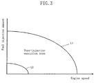
- the post-injection is carried out only in a post-injection execution zone defined by the preset curves L1 and L2 .
- the operating zone outside of the preset curve L1 is a naturally regenerable zone where the engine speed and load are high and the exhaust gas temperature is originally high. In this zone, execution of post-injection is inhibited because it invites excessively high exhaust gas temperature by contrast to have an adverse effect on the thermal endurance of exhaust system elements.
- the operating zone inside of the preset curve L2 is the zone where the engine speed and load are low and the exhaust gas temperature is low. In this zone, even if post-injection is executed, the exhaust gas temperature will not reach the temperature at which exhaust particulates can burn. Therefore, post-injection is inhibited to suppress deterioration in fuel economy.
- the engine control unit 30 is provided with a deceleration detecting means 30c for detecting a deceleration condition of the engine based on the amount of change in accel opening, a fuel injection cutoff means 30d for cutting off fuel injection of the fuel injection valve 20 when the deceleration detecting means 30c detects a deceleration condition, and a fuel injection cutoff inhibition means 30e for inhibiting fuel injection cutoff of the fuel injection cutoff means 30d when a deceleration condition is detected while the regeneration means 30b is regenerating the particulate filter 12 .
- a deceleration detecting means 30c for detecting a deceleration condition of the engine based on the amount of change in accel opening
- a fuel injection cutoff means 30d for cutting off fuel injection of the fuel injection valve 20 when the deceleration detecting means 30c detects a deceleration condition
- a fuel injection cutoff inhibition means 30e for inhibiting fuel injection cutoff of the fuel injection cutoff means 30d when a
- the engine control unit 30 is further provided with an exhaust gas recirculation amount setting means (EGR amount setting means) 30f for setting the EGR amount with reference to a map plotted between engine speed and fuel injection amount (which is calculated based on the accel opening and the engine speed), and an exhaust gas recirculation amount compensation means (EGR amount compensation means) 30g for compensating for the EGR amount set by the EGR amount setting means 30f by subtracting some given amount from the set EGR amount when a deceleration condition is detected by the deceleration detecting means 30c .
- the map is plotted by previously assigning optimal EGR amounts according to engine speed and fuel injection amount.
- the engine control unit 30 is further provided with an intake throttle valve opening setting means 30h for setting the opening angle of the intake throttle valve 8 with reference to a map plotted between engine speed and fuel injection amount, and an intake throttle valve opening compensation means 30i for additively compensating for the opening angle of the intake throttle valve 8 set by the intake throttle valve opening setting means 30h to become wider by some given value when a deceleration condition has been detected by the deceleration detecting means 30c .
- the map is plotted by previously assigning optimal opening angles of the intake throttle valve according to engine speed and fuel injection amount.
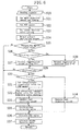
- step S1 of Figure 4 detection signals from various sensors such as the exhaust pressure sensors 13 and 14 , the fuel injection pressure sensor 21 , the crank angle sensor 23 and the accel opening sensor 24 are read.
- step S2 the main injection amount of fuel injected in the vicinity of the top dead centre on the compression stroke is set by referring to a main injection amount map based on the engine speed and the accel opening, and the main injection timing is set by referring to a main injection timing map based on the engine speed and the fuel injection amount.
- the main injection amount map is plotted by previously assigning optimal main injection amounts according to engine speed and accel opening.
- the main injection timing map is plotted by previously assigning optimal main injection timings according to engine speed and fuel injection amount.
- step S3 the EGR amount is set by referring to the related map based on the engine speed and the fuel injection amount. In this map, the EGR amounts are assigned to become larger as the engine speed is decreased or as the fuel injection amount is reduced.
- step S4 the opening angle of the intake throttle valve is set by referring to the related map based on the engine speed and the fuel injection amount.
- the opening angles of the intake throttle valve are assigned to become smaller (to approach its closed position) as the engine speed is decreased or as the fuel injection amount is reduced.
- step S5 the amount of exhaust particulate trapped by the particulate filter 12 is detected based on the differential pressure between the exhaust pressure sensors 13 and 14 .
- step S6 it is determined whether or not the amount of exhaust particulate detected in step S5 is above a first predetermined value equivalent to the saturation amount for the particulate filter 12 .
- step S6 determines whether the particulate filter 12 has trapped exhaust particulates to an extent equivalent to its saturation amount, it is necessary to remove the exhaust particulates by burning and thereby regenerate the particulate filter 12 .
- the program proceeds to step S7 wherein the post-injection amount and post-injection timing (here, both fixed values) are set, and then proceeds to step S8 wherein a forced regeneration execution flag F is set at 1.
- step S6 determines whether or not the amount of exhaust particulate is below a second predetermined value (the value set to be smaller than the first predetermined value, e.g., a value near to zero).
- a second predetermined value the value set to be smaller than the first predetermined value, e.g., a value near to zero.
- step S9 If the determination in step S9 is NO, this shows that the amount of exhaust particulate trapped is still large. In this case, the program proceeds to step S7 wherein the post-injection amount and post-injection timing are set as described above.
- step S9 determines whether the particulate filter 12 is regenerated sufficiently. If the determination in step S9 is YES, i.e., if the particulate filter 12 is regenerated sufficiently, the program proceeds to step S10, without setting the post-injection amount and timing, in which the forced regeneration execution flag F is set at 0.
- step S11 it is determined whether or not the engine enters a deceleration condition. If the determination is YES, the program proceeds to step S12 wherein it is determined whether or not the forced regeneration execution flag F is set at 1 .
- step S12 determines whether the operating condition changes to a deceleration condition during the removal by burning of exhaust particulates. If the determination in step S12 is YES, i.e., when the operating condition changes to a deceleration condition during the removal by burning of exhaust particulates, the program proceeds to steps S13 , S14 and S15 in this order to execute the process for restricting the drop of the flow rate of exhaust gases flowing into the particulate filter 12 .
- step S13 the subtractive compensated value for the EGR amount (here, a fixed value regardless of any operating conditions) is first set.
- the amount of exhaust gases recirculated to the intake path 2 is reduced. Therefore, the flow rate of exhaust gases flowing into the particulate filter 12 can be increased by the reduced EGR amount.
- step S14 the additive compensated value for the opening angle of the intake throttle valve 8 (here, a fixed value regardless of any operating conditions) is set.
- the amount of air taken into the engine is increased. Therefore, the flow rate of exhaust gases emitted from the engine can be increased by the increased air amount.
- step S15 fuel injection cutoff during engine deceleration is inhibited. This restricts drop in engine speed during deceleration to increase the amount of air taken into the engine. Therefore, the flow rate of exhaust gases emitted from the engine can be increased accordingly.
- step S12 determines whether the determination in step S12 is NO. If the determination in step S12 is NO, the program proceeds to step S16 , without compensating for the EGR amount and the opening angle of the intake throttle valve 8 , in which fuel injection cutoff during engine deceleration is carried out.
- step S11 determines whether the determination in step S11 is NO, the program proceeds to step S17 without executing the procedures in steps S13 to S15 .
- step S17 the fuel injection valve 20 is activated such that main fuel injection is carried out according to the main injection amount and main injection timing set in step S2 , or such that when the post-injection amount and post-injection timing have been set in step S7 , post-injection is additionally carried out.
- step S18 the EGR valve 16 is activated to provide a final EGR amount determined based on the EGR amount set in step S3 and the subtractive compensated value for the EGR amount set in the step S13 .
- step S19 the actuator (not shown) for the intake throttle valve 8 is activated to provide a final opening angle of the intake throttle valve which is determined based on the intake throttle vale opening angle set in step S4 and the additive compensated value for the intake throttle valve opening set in step S14 .
- Embodiment 1 as shown in the time chart of Figure 5 , when the engine enters a deceleration condition under the condition that exhaust particulates are being removed by burning, the opening angle of the EGR valve 16 is decreased to reduce the EGR amount as shown in the solid line in the chart.
- the opening angle of the intake throttle valve 8 is increased as shown in the solid line in the chart, and fuel injection cutoff during deceleration is inhibited so that fuel is injected at the amount equivalent to that injected during idling as shown in the solid line in the chart.
- the drop of the flow rate of exhaust gases flowing into the particulate filter 12 can be restricted, resulting in suppression of temperature rise in the particulate filter 12 .
- Embodiment 2 is the case of restricting, on engine deceleration during a natural regeneration, the drop of the flow rate of exhaust gases flowing into the particulate filter 12 .
- the specific measures for restricting the drop of the flow rate of exhaust gases includes, like Embodiment 1, (a) compensating for the amount of recirculation of exhaust gases (EGR amount) subtractively, (b) compensating for the opening angle of the intake throttle valve 8 to become wider, and (c) inhibiting fuel injection cutoff during engine deceleration.
- Steps S20 to S24 in Figure 6 are the same as steps S1 to S5 in Figure 4 , and therefore the description of them will be omitted.
- step S25 it is determined whether or not the amount of exhaust particulate detected in step S24 is above a third predetermined value (the value set to be smaller than the first predetermined value but larger than the second predetermined value, each described in Embodiment 1), i.e., whether or not the conditions that a certain amount of exhaust particulate has been trapped and the temperature of the particulate filter 12 will rise by burning on engine deceleration hold true.
- a third predetermined value the value set to be smaller than the first predetermined value but larger than the second predetermined value, each described in Embodiment 1
- step S25 If the determination in step S25 is YES, the program proceeds to step S26 wherein it is determined whether or not the operating zone lies outside of the preset curve L1 shown in Figure 3 .
- step S26 determines whether the operating condition lies in the natural regeneration zone. If the determination in step S26 is YES, i.e., when it has been determined that the operating condition lies in the natural regeneration zone, the program proceeds to step S27 wherein a natural regeneration flag F is set at 1. If the determination in step S26 is NO, the program proceeds to step S28 wherein the natural regeneration flag F is set at 0.
- step S29 to S37 are the same as steps S11 to S19 in Figure 4 , and therefore the detailed description of them will be omitted.
- the program carries out the procedures in step S31 to S33 to reduce the EGR amount, increase the opening angle of the intake throttle valve 8 and inhibit fuel injection cutoff during deceleration, resulting in restricting the drop of the flow rate of exhaust gases flowing into the particulate filter 12.
- Embodiment 2 even when the engine operating condition changes to a deceleration condition while in the natural regeneration zone outside of the preset curve L1 of Figure 3 in which exhaust particulates are removed by burning, like the change to a deceleration condition during the forced regeneration, the EGR amount is reduced, the opening angle of the intake throttle valve 8 is increased and fuel injection cutoff on deceleration is inhibited.
- the drop of the flow rate of exhaust gases flowing into the particulate filter 12 can be restricted, resulting in suppression of the temperature rise of the particulate filter 12 .
- Embodiment 3 is the case that when the engine enters a deceleration condition under the condition in which exhaust particulates are removed by burning, the shift lines for changing the gear ratio of an automatic transmission are compensated for to a higher vehicle speed side to increase the engine speed and in turn increase the amount of air taken into the engine, or to restrict the drop of the engine speed, resulting in restricting the drop of the flow rate of exhaust gases flowing into the particulate filter 12 .
- Figure 7 is a control block diagram of Embodiment 3.
- the engine control unit 30 is provided, like Embodiments 1 and 2, with an exhaust particulate amount detecting means 30a and regeneration means 30b in order to control the fuel injection valve 20 to remove exhaust particulates by burning.
- the exhaust particulate after-treatment system of this embodiment further includes an automatic transmission control unit 40 .
- the automatic transmission control unit 40 receives detection signals of the accel opening sensor 24 and a vehicle speed sensor 26 for the control of a shift solenoid 25 for an automatic transmission (not shown).
- the automatic transmission control unit 40 is provided with a deceleration detecting means 40a for detecting deceleration based on the amount of change in accel opening, a gear ratio setting means 40b for setting the gear ratio based on shift lines previously assigned according to accel opening and vehicle speed, and shift line compensation means 40c for compensating for the shift lines of the gear ratio setting means 40b to a higher vehicle speed side when a deceleration condition of the engine is detected by the deceleration detecting means 40a under the conditions that the amount of exhaust particulate detected by the exhaust particulate amount detecting means 30a has reached the first predetermined value or more and the exhaust particulates are being removed by burning.
- step S40 of Figure 8 detection signals from various sensors such as the exhaust pressure sensors 13 and 14 , the accel opening sensor 24 and the vehicle speed sensor 25 are read.
- the main injection amount of fuel injected in the vicinity of the top dead centre on the compression stroke is set by referring to a main injection amount map based on the engine speed and the accel opening
- the main injection timing is set by referring to a main injection timing map based on the engine speed and the fuel injection amount.
- step S42 the amount of exhaust particulate trapped by the particulate filter 12 is detected based on the differential pressure between the exhaust pressure sensors 13 and 14.
- step S43 it is determined whether or not the amount of exhaust particulate detected in step S42 is above a first predetermined value equivalent to the saturation amount for the particulate filter 12 .
- step S43 determines whether the particulate filter 12 has trapped exhaust particulates to an extent equivalent to its saturation amount, it is necessary to remove the exhaust particulates by burning and thereby regenerate the particulate filter 12 .
- the program proceeds to step S44 wherein the post-injection amount and post-injection timing (here, both fixed values) are set, and then proceeds to step S45 wherein a forced regeneration execution flag F is set at 1.
- step S43 determines whether or not the amount of exhaust particulate is below a second predetermined value (the value set to be smaller than the first predetermined value, e.g., a value near to zero).
- a second predetermined value the value set to be smaller than the first predetermined value, e.g., a value near to zero.
- step S46 If the determination in step S46 is NO, this shows that the amount of exhaust particulate trapped is still large. In this case, the program proceeds to step S44 wherein the post-injection amount and post-injection timing are set as described above.
- step S46 determines whether the particulate filter 12 is generated sufficiently. If the determination in step S46 is YES, i.e., if the particulate filter 12 is generated sufficiently, the program proceeds to step S47 , without setting the post-injection amount and timing, in which the forced regeneration execution flag F is set at 0.
- step S48 it is determined whether or not the engine enters a deceleration condition.
- step S48 If the determination in step S48 is YES, the program proceeds to step S49 wherein it is determined whether or not the forced regeneration execution flag F is set at 1.
- step S49 determines whether the determination in step S49 is YES, i.e., when the engine operating condition shifts to a deceleration condition during the removal by burning of exhaust particulates.
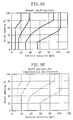
- the program proceeds to step S50 wherein a shift pattern for regeneration deceleration shown in Figure 9B is set as a shift pattern for the automatic transmission.
- step S49 determines whether the determination in step S49 is NO. If the determination in step S49 is NO, the program proceeds to step S51 wherein a normal shift pattern shown in Figure 9A is set as a shift pattern for the automatic transmission.
- step S48 If the determination in step S48 is NO, the program proceeds to step S51.
- step S52 the fuel injection valve 20 is activated such that main fuel injection is carried out according to the main injection amount and main injection timing set in step S41 , or such that when the post-injection amount and post-injection timing have been set in step S44 , post-injection is additionally carried out.
- step S53 the shift solenoid 25 is activated such that the gear ratio is controlled according to the shift pattern set in either step S50 or step S51 .
- Embodiment 3 when the engine enters a deceleration condition under the condition that exhaust particulates are removed by burning, the shift lines for changing the gear ratio of the automatic transmission are compensated for to a higher vehicle speed side.
- the engine speed can be increased to increase the amount of air taken into the engine, or the drop of the engine speed can be restricted. Therefore, the drop of the flow rate of exhaust gases flowing into the particulate filter 12 can be restricted.
- Embodiment 3 the shift lines for changing the gear ratio of the automatic transmission is compensated for to a higher vehicle speed side when the engine enters a deceleration condition under the condition that exhaust particulates are removed by burning.
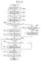
- Embodiment 4 is the case of forcibly changing the gear ratio, which is set according to the shift lines, to a one-stage lower speed side instead of compensating for the shift lines.
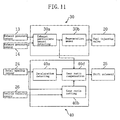
- FIG 11 is a control block diagram of Embodiment 4. This embodiment is the same as Embodiment 3, except that a gear ratio compensation means 40b is provided instead of the shift line compensation means 40c in Embodiment 3.
- the gear ratio compensation means 40d is configured to forcibly compensate for the gear ratio set by the gear ratio setting means 40b to a one-stage lower speed side.
- step S60 of Figure 12 detection signals from various sensors such as the exhaust pressure sensors 13 and 14 , the accel opening sensor 24 and the vehicle speed sensor 25 are read.
- the main injection amount of fuel injected in the vicinity of the top dead centre on the compression stroke is set by referring to a main injection amount map based on the engine speed and the accel opening
- the main injection timing is set by referring to a main injection timing map based on the engine speed and the fuel injection amount.
- step S62 the gear ratio is set according to the accel opening and vehicle speed at the time with reference to a normal shift pattern (for example, Figure 9A as described above).
- step S63 the amount of exhaust particulate trapped by the particulate filter 12 is detected based on the differential pressure between the exhaust pressure sensors 13 and 14 .
- step S64 it is determined whether or not the amount of exhaust particulate detected in step S63 is above a first predetermined value equivalent to the saturation amount for the particulate filter 12 .
- step S64 determines whether the particulate filter 12 has trapped exhaust particulates to an extent equivalent to its saturation amount, it is necessary to remove the exhaust particulates by burning and thereby regenerate the particulate filter 12 .
- the program proceeds to step S65 wherein the post-injection amount and post-injection timing (here, both fixed values) are set, and then proceeds to step S66 wherein a forced regeneration execution flag F is set at 1.
- step S64 determines whether or not the amount of exhaust particulate is below a second predetermined value (the value set to be smaller than the first predetermined value, e.g., a value near to zero).
- a second predetermined value the value set to be smaller than the first predetermined value, e.g., a value near to zero.
- step S67 If the determination in step S67 is NO, this shows that the amount of exhaust particulate trapped is still large. In this case, the program proceeds to step S65 wherein the post-injection amount and post-injection timing are set as described above.
- step S67 determines whether the particulate filter 12 is regenerated sufficiently. If the determination in step S67 is YES, i.e., if the particulate filter 12 is regenerated sufficiently, the program proceeds to step S68 , without setting the post-injection amount and timing and changing the gear ratio to a lower-speed stage side, in which the forced regeneration execution flag F is set at 0.
- step S69 it is determined whether or not the engine enters a deceleration condition.
- step S69 If the determination in step S69 is YES, the program proceeds to step S70 wherein it is determined whether or not the forced regeneration execution flag F is set at 1.
- step S70 determines whether the gear ratio set in step S62 is compensated for to a one-stage lower speed side.
- step S70 determines whether the procedure in step S71 and jumps to step S72 .
- step S69 If the determination in step S69 is NO, the program also jumps to step S72 .
- step S72 the fuel injection valve 20 is activated such that main fuel injection is carried out according to the main injection amount and main injection timing set in step S61 , or such that when the post-injection amount and post-injection timing have been set in step S65 , post-injection is additionally carried out.
- step S73 the shift solenoid 25 is activated such that the gear ratio is either the value set in step S62 or the value changed in step S71 .
- Embodiment 4 when the engine enters a deceleration condition under the condition that exhaust particulates are removed by burning, the gear ratio of the automatic transmission is compensated for to a one-stage lower speed side.
- the engine speed can be increased to increase the amount of air taken into the engine. Therefore, the drop of the flow rate of exhaust gases flowing into the particulate filter 12 can be restricted.
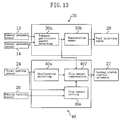
- Embodiment 5 is the case that when the engine enters a deceleration condition under the condition that exhaust particulates are removed by burning, the slip amount between input and output members of a torque converter (not shown) as a fluid coupling equipped with an automatic transmission is changed to increase.
- Figure 13 is a control block diagram of Embodiment 5.
- the engine control unit 30 is provided, like Embodiments 1 and 2, with an exhaust particulate amount detecting means 30a and regeneration means 30b in order to control the fuel injection valve 20 to remove exhaust particulates by burning.
- the exhaust particulate after-treatment system of this embodiment further includes an automatic transmission control unit 40 .
- the automatic transmission control unit 40 receives detection signals of the accel opening sensor 24 and the vehicle speed sensor (not shown), and allows a lockup clutch control solenoid 27 to control a lockup clutch (not shown) for adjusting the engagement condition (slip amount) between the input and output members of the torque converter (not shown).
- the automatic transmission control unit 40 is provided with a deceleration detecting means 40a for detecting deceleration based on the amount of change in accel opening, a slip amount setting means 40e for setting the slip amount according to the accel opening and the vehicle speed, and a shift amount compensation means 40f for changing the slip amount set by the slip amount setting means 40e to increase it when an engine deceleration condition is detected by the deceleration detecting means 40a under the conditions that the amount of exhaust particulate detected by the exhaust particulate amount detecting means 30a has reached the first predetermined value or more and the exhaust particulates are being removed by burning.
- step S80 of Figure 14 detection signals from various sensors such as the exhaust pressure sensors 13 and 14 , the accel opening sensor 24 and the vehicle speed sensor 25 are read.
- the main injection amount of fuel injected in the vicinity of the top dead centre on the compression stroke is set by referring to a main injection amount map based on the engine speed and the accel opening
- the main injection timing is set by referring to a main injection timing map based on the engine speed and the fuel injection amount.
- step S82 the slip amount is set by referring to a slip amount map based on the accel opening and the vehicle speed.
- step S83 the amount of exhaust particulate trapped by the particulate filter 12 is detected based on the differential pressure between the exhaust pressure sensors 13 and 14 .
- step S84 it is determined whether or not the amount of exhaust particulate detected in step S83 is above a first predetermined value equivalent to the saturation . amount for the particulate filter 12 .
- step S84 determines whether the particulate filter 12 has trapped exhaust particulates to an extent equivalent to its saturation amount, it is necessary to remove the exhaust particulates by burning and thereby regenerate the particulate filter 12 .
- the program proceeds to step S85 wherein the post-injection amount and post-injection timing (here, both fixed values) are set, and then proceeds to step S86 wherein a forced regeneration execution flag F is set at 1.
- step S84 determines whether or not the amount of exhaust particulate is below a second predetermined value (the value set to be smaller than the first predetermined value, e.g., a value near to zero).
- a second predetermined value the value set to be smaller than the first predetermined value, e.g., a value near to zero.
- step S87 If the determination in step S87 is NO, this shows that the amount of exhaust particulate trapped is still large. In this case, the program proceeds to step S85 wherein the post-injection amount and post-injection timing are set as described above.
- step S87 determines whether the particulate filter 12 is regenerated sufficiently. If the determination in step S87 is YES, i.e., if the particulate filter 12 is regenerated sufficiently, the program proceeds to step S88 , without setting the post-injection amount and timing and changing the gear ratio to a lower-speed stage side, in which the forced regeneration execution flag F is set at 0.
- step S89 it is determined whether or not the engine enters a deceleration condition.
- step S89 determines whether or not the forced regeneration execution flag F is set at 1.
- step S90 determines whether the determination in step S90 is YES, i.e., when the engine operating condition has changed to a deceleration condition during the removal by burning of exhaust particulates.
- the program proceeds to step S91 wherein the slip amount set in step S82 is additively compensated for by some given amount (in this case, a fixed amount).
- step S90 determines whether the procedure in step S91 and jumps to step S92 .
- step S89 If the determination in step S89 is NO, the program also jumps to step S92 .
- step S92 the fuel injection valve 20 is activated such that main fuel injection is carried out according to the main injection amount and main injection timing set in step S81 , or such that when the post-injection amount and post-injection timing have been set in step S85, post-injection is additionally carried out.
- step S93 the lockup clutch control solenoid 27 is activated such that the slip amount is either the value set in step S82 or the value changed in step S91 .
- Embodiment 5 when the engine enters a deceleration condition under the condition that exhaust particulates are removed by burning, the slip amount of the torque converter is additively compensated for.
- the engine speed can be increased to increase the amount of air taken into the engine. Therefore, the drop of the flow rate of exhaust gases flowing into the particulate filter 12 can be restricted.
- Embodiments 1 and 2 disclose the case where the EGR amount set in the EGR map is reduced by a fixed amount when the engine enters a deceleration condition under the condition that exhaust particulates are removed by burning.
- individual EGR maps may be plotted for the normal condition and the condition where the engine enters a deceleration condition while exhaust particulates are being removed by burning, respectively, and both the maps may be separately used for the two conditions to reduce the EGR amount.
- Embodiments 1 and 2 disclose the case where the EGR amount set in the EGR map is reduced by a fixed amount when the engine enters a deceleration condition under the condition that exhaust particulates are removed by burning. At the time, the EGR amount may be reduced to zero.
- Embodiments 1 and 2 disclose the case where the intake throttle valve opening set in the intake throttle valve opening map is compensated for to become wider by some given amount when the engine enters a deceleration condition under the condition that exhaust particulates are removed by burning.
- individual intake throttle valve opening maps may be plotted for the normal condition and the condition where the engine enters a deceleration condition while exhaust particulates are being removed by burning, respectively, and both the maps may be separately used for two conditions to additively compensate for the intake throttle valve opening.
- Embodiments 1 and 2 disclose the case where a several kinds of engine controls including subtractive compensation of the EGR amount, additive compensation of the intake throttle valve opening and inhibition of fuel injection cutoff are carried out in combination.
- at least one of the above engine controls may be carried out in combination with at least one of the automatic transmission controls including compensation of the shift lines for the automatic transmission to a higher vehicle speed side, compensation of the gear ratio to a one-stage lower speed side, and additive compensation of the slip amount.
- Embodiments 3 to 5 disclose the cases that when the engine enters a deceleration condition during execution of forced regeneration, the shift lines are compensated for to a higher vehicle speed side, the gear ratio is compensated for to a one-stage lower speed side, and the slip amount is additively compensated for, respectively. Similar controls may also be conducted when the operating condition enters a deceleration condition under a natural regeneration condition lying in the operating zone outside of the preset curve L1 in Figure 3 .
- the fuel injection timing for main injection may be retarded to cause afterburning.
- the particulate filter 12 may be provided with a heater so that exhaust particulates can be removed by burning with the heater.
- a deceleration condition is detected based on the amount of change in accel opening.
- various kinds of manners to detect a deceleration condition are applicable to this invention.
- a deceleration condition may be detected based on the amount of change in engine speed.
- the engine speed is an idling speed or more and the accel opening is narrowed to the opening corresponding to an idling operation, it may be detected as a deceleration condition.
- the controls in the present invention are carried out by storing the computer programs for the controls in memories of the engine control unit 30 and the automatic transmission control unit 40.
- Such controls may be carried out by storing the computer programs in a storage media (such as a CD-ROM) separate from the control units 30 and 40 .
- the controls may be carried out by obtaining the computer programs through a wireless communication means such as the Internet and storing the obtained programs in a writable ROM.
Landscapes
- Engineering & Computer Science (AREA)
- Chemical & Material Sciences (AREA)
- Combustion & Propulsion (AREA)
- Mechanical Engineering (AREA)
- General Engineering & Computer Science (AREA)
- Analytical Chemistry (AREA)
- Physics & Mathematics (AREA)
- Fluid Mechanics (AREA)
- Chemical Kinetics & Catalysis (AREA)
- Processes For Solid Components From Exhaust (AREA)
- Combined Controls Of Internal Combustion Engines (AREA)
- Electrical Control Of Air Or Fuel Supplied To Internal-Combustion Engine (AREA)
- Exhaust-Gas Circulating Devices (AREA)
- Output Control And Ontrol Of Special Type Engine (AREA)
- Control Of Vehicle Engines Or Engines For Specific Uses (AREA)
- Control Of Fluid Gearings (AREA)
- Control Of Driving Devices And Active Controlling Of Vehicle (AREA)
- Control Of Throttle Valves Provided In The Intake System Or In The Exhaust System (AREA)
- Control Of Transmission Device (AREA)
- Exhaust Gas After Treatment (AREA)
Abstract
Description
- This invention relates to an engine exhaust particulate after-treatment system.
- For the purpose of purification of exhaust gases from diesel engines, there has been recently employed a technology for trapping exhaust particulates such as carbon contained in exhaust gases by a particulate filter disposed in an exhaust path of the engine to prevent atmospheric release.
- In such a diesel engine provided with a particulate filter, when the amount of exhaust particulate accumulated on the particulate filter reaches a saturation amount which is the limit to which the particulate filter can accumulate exhaust particulates, it is necessary to burn the accumulated exhaust particulates to regenerate the function of the filter.
- As an example of filter regeneration techniques, there is known one for burning exhaust particulates in such a manner to raise the exhaust gas temperature by operating a heater provided in the particulate filter or by retarding the timing of fuel injection from a fuel injection valve behind that during normal operation to promote after-burning.
- In the above known technique, however, if the engine operating condition changes to a deceleration condition in the course of regeneration of the particulate filter, this may cause a problem that the temperature of the particulate filter may rise suddenly to deteriorate the durability thereof.
- More specifically, while the particulate filter during regeneration raises its temperature as a result of the burning of exhaust particulates, it suddenly raises its temperature, when the exhaust gas flow rate decreases due to vehicle deceleration, because the particulate filter attenuates its cooling action caused by the passage of exhaust gases therethrough (a cooling action caused by heat exchange between the exhaust gases and the particulate filter).
- Japanese Examined Patent Publication No. 5-11205 discloses a technique for suppressing dissolution loss of a particulate filter, when the engine operating mode shifts from a high load to idling condition and the temperature of the particulate filter and the oxygen concentration in exhaust gases then exceed their predetermined levels, by reducing the oxygen concentration in the exhaust gases to below the predetermined level.
- This known art technique, however, does not approach the problem of dissolution loss of the particulate filter until the engine operating mode has shifted from a high load to idling condition and the temperature of the particulate filter increases, and does not intend to prevent the occurrence of temperature rise of the particulate filter on engine deceleration which means the period of transition from a high load to idling condition. Therefore, the above problem cannot be solved by this known art technique, nor has it still been solved.
- An object of the present invention is to provide an engine exhaust particulate after-treatment system that can suppress the temperature rise of a particulate filter on engine deceleration during the removal of exhaust particulates.
- Another object of the present invention is to provide a computer program for suppressing the temperature rise of a particulate filter on engine deceleration during the removal of exhaust particulates.
- To attain the first-mentioned object, the present invention is directed to an engine exhaust particulate after-treatment system comprising exhaust particulate trapping means provided in an exhaust path of an engine for trapping particulates in exhaust gases, and characterised by further comprising exhaust flow rate drop restriction means for restricting, on deceleration of the engine during the removal by burning of exhaust particulates trapped by the exhaust particulate trapping means, the drop of the flow rate of exhaust gases flowing into the exhaust particulate trapping means.
- According to the present invention, even when the engine enters a deceleration condition during the removal by burning of exhaust particulates, restriction is made to the drop in the flow rate of exhaust gases flowing into the exhaust particulate trapping means. Therefore, the cooling action of the exhaust particulate trapping means through heat exchange with the exhaust gases can be kept up to suppress the temperature rise of the exhaust particulate trapping means.
- Preferably, the above engine exhaust particulate after-treatment system further comprises deceleration detecting means for detecting a deceleration condition of the engine, and operating condition detecting means for detecting an operating condition of the engine in which the exhaust gases are in such a high temperature range that the exhaust particulates trapped by the exhaust particulate trapping means can be removed by burning, and is configured to restrict, on the detection of the deceleration condition of the engine when the engine operating condition in which the exhaust gases are in the high temperature range is detected, the drop of the flow rate of exhaust gases flowing into the exhaust particulate trapping means.
- With this structure, even when the engine enters a deceleration condition while it is in an operating condition in which the exhaust gases are in the range of high temperatures and the exhaust particulates are removed by burning, the cooling action of the exhaust particulate trapping means through heat exchange with the exhaust gases is kept up, which suppresses the temperature rise of the exhaust particulate trapping means.
- Preferably, the engine exhaust particulate after-treatment system further comprises exhaust particulate amount detecting means for directly or indirectly detecting the amount of exhaust particulate trapped by the exhaust particulate trapping means, regeneration means for removing exhaust particulates trapped by the exhaust particulate trapping means by burning when the amount of exhaust particulate detected by the exhaust particulate amount detecting means reaches a predetermined value, and deceleration detecting means for detecting a deceleration condition of the engine, and is configured to restrict, when a deceleration condition of the engine is detected during the removal by burning of exhaust particulates by the regeneration means, the drop of the flow rate of exhaust gases flowing into the exhaust particulate trapping means.
- With this structure, even when the engine enters a deceleration condition while the exhaust particulates are removed by burning by the action of the regeneration means, the cooling action of the exhaust particulate trapping means through heat exchange with the exhaust gases is kept up, which suppresses the temperature rise of the exhaust particulate trapping means on engine deceleration.
- More preferably, the engine exhaust particulate after-treatment system further comprises an exhaust gas recirculation path for communicating part of the exhaust path upstream of the exhaust particulate trapping means with an intake path of the engine, an exhaust gas recirculation valve disposed in the exhaust gas recirculation path, exhaust gas recirculation amount setting means for setting the amount of recirculation of exhaust gases through the exhaust gas recirculation valve according to the operating condition of the engine, and exhaust gas recirculation amount compensation means for compensating for the amount of recirculation of exhaust gases set by the exhaust gas recirculation amount setting means, wherein the exhaust flow rate drop restriction means is formed by the exhaust gas recirculation amount compensation means, and when a deceleration condition of the engine is detected by the deceleration detecting means during the removal by burning of exhaust particulates, the exhaust gas recirculation amount compensation means subtractively compensates for the amount of recirculation of exhaust gases set by the exhaust gas recirculation amount setting means.
- With this structure, even when the engine enters a deceleration condition during the removal by burning of exhaust particulates, the amount of recirculation of exhaust gases is controlled to reduce it. The rate of the amount of exhaust gases supplied to the exhaust particulate trapping means with respect to the total amount of exhaust gases emitted from the engine can be increased. Therefore, the drop of the amount of exhaust gases supplied to the exhaust particulate trapping means is restricted, which suppresses the temperature rise of the exhaust particulate trapping means on engine deceleration.
- As can be seen from the above, the following engine exhaust particulate after-treatment system is effective in attaining the first object of the present invention.
- Namely, the engine exhaust particulate after-treatment system comprises:
- a filter provided in an exhaust path of an engine for trapping particulates in exhaust gases;
- a sensor for detecting the amount of exhaust particulate trapped by the filter;
- an exhaust gas recirculation path for communicating part of the exhaust path upstream of the filter with an intake path of the engine;
- an exhaust gas recirculation valve disposed in the exhaust gas recirculation path;
- an injector for injecting fuel directly into a combustion chamber of the engine;
- a deceleration sensor for detecting a deceleration condition of the engine; and
- a control unit for controlling the operations of the injector and the exhaust gas recirculation valve using a computer, wherein the control unit controls the injector to carry out a main injection of fuel in the vicinity of the top dead centre on the compression stroke to obtain engine power,
-
- Preferably, the engine exhaust particulate after-treatment system further comprises an intake throttle valve disposed in an intake path of the engine, intake throttle valve opening setting means for setting the opening of the intake throttle valve according to the operating condition of the engine, and intake throttle valve opening compensation means for compensating for the opening of the intake throttle valve set by the intake throttle valve opening setting means, wherein the exhaust flow rate drop restriction means is formed by the intake throttle valve opening compensation means, and when a deceleration condition of the engine is detected by the deceleration detecting means during the removal by burning of exhaust particulates, the intake throttle valve opening compensation means compensates for the opening of the intake throttle valve, which is controlled according to the engine operating condition, to become wider.
- With this structure, even when the engine enters a deceleration condition during the removal by burning of exhaust particulates, the opening angle of the intake throttle valve is controlled to be a greater degree. Therefore, the amount of air taken into the engine is increased to restrict the drop of the flow rate of exhaust gases, which suppresses the temperature rise of the exhaust particulate trapping means.
- The exhaust flow rate drop restriction means may be formed by the exhaust gas recirculation amount compensation means and the intake throttle valve opening compensation means.
- Preferably, the engine exhaust particulate after-treatment system further comprises fuel injection means for injecting fuel into a combustion chamber of the engine, fuel injection cutoff means for cutting off fuel injection of the fuel injection means when a deceleration condition of the engine is detected by the deceleration detecting means, and fuel injection cutoff inhibition means for inhibiting the operation of the fuel injection cutoff means, wherein the exhaust flow rate drop restriction means is formed by the fuel injection cutoff inhibition means, and when a deceleration condition of the engine is detected by the deceleration detecting means during the removal by burning of exhaust particulates, the fuel injection cutoff inhibition means inhibits the fuel injection cutoff means from cutting off fuel injection.
- With this structure, even when the engine enters a deceleration condition during the removal by burning of exhaust particulates, the cutoff of fuel injection is inhibited. It is therefore prevented that the engine speed decreases, i.e., that the amount of air taken into the engine is reduced. As a result, the drop of the flow rate of exhaust gases is restricted, which suppresses the temperature rise of the exhaust particulate trapping means on engine deceleration.
- The exhaust flow rate drop restriction means may be formed by at least one of the exhaust gas recirculation amount compensation means and the intake throttle valve opening compensation means, and the fuel injection cutoff inhibition means.
- Preferably, the engine exhaust particulate after-treatment system further comprises an automatic transmission, gear ratio setting means for setting the gear ratio of the automatic transmission based on predetermined shift lines according to the running conditions of a vehicle, and shift line compensation means for compensating for the shift lines of the gear ratio setting means, wherein the exhaust flow rate drop restriction means is formed by the shift line compensation means, and when a deceleration condition of the engine is detected by the deceleration detecting means during the removal by burning of exhaust particulates, the shift line compensation means compensates for the shift lines of the gear ratio setting means to a higher vehicle speed side.
- With this structure, even when the engine enters a deceleration condition during the removal by burning of exhaust particulates, the shift lines are compensated for to a higher vehicle speed side so that the engine speed increases and therefore the amount of air taken into the engine is increased, or the engine speed is kept up. As a result, the drop of the flow rate of exhaust gases is restricted, which suppresses the temperature rise of the exhaust particulate trapping means on engine deceleration.
- The exhaust flow rate drop restriction means may be formed by at least one of the exhaust gas recirculation amount compensation means, the intake throttle valve opening compensation means and the fuel injection cutoff inhibition means, and the shift line compensation means.
- Preferably, the engine exhaust particulate after-treatment system further comprises an automatic transmission, gear ratio setting means for setting the gear ratio of the automatic transmission based on predetermined shift lines according to the running conditions of a vehicle, and gear ratio compensation means for compensating for the gear ratio set by the gear ratio setting means, wherein the exhaust flow rate drop restriction means is formed by the gear ratio compensation means, and when a deceleration condition of the engine is detected by the deceleration detecting means during the removal by burning of exhaust particulates, the gear ratio compensation means compensates for the gear ratio set by the gear ratio setting means to a lower-speed stage side.
- With this structure, even when the engine enters a deceleration condition during the removal by burning of exhaust particulates, the gear stage is compensated for to a lower-speed stage side so that the engine speed increases and therefore the amount of air taken into the engine is increased. As a result, the drop of the flow rate of exhaust gases is restricted, which suppresses the temperature rise of the exhaust particulate trapping means on engine deceleration.
- The exhaust flow rate drop restriction means may be formed by at least one of the exhaust gas recirculation amount compensation means, the intake throttle valve opening compensation means and the fuel injection cutoff inhibition means, and the gear ratio compensation means.
- Preferably, the engine exhaust particulate after-treatment system further comprises an automatic transmission, slip amount setting means for setting the slip amount between input and output members of a fluid coupling equipped with the automatic transmission according to the running conditions of a vehicle, and slip amount compensation means for compensating for the slip amount set by the slip amount setting means, wherein the exhaust flow rate drop restriction means is formed by the slip amount compensation means, and when a deceleration condition of the engine is detected by the deceleration detecting means during the removal by burning of exhaust particulates, the slip amount compensation means additively compensates for the slip amount set by the slip amount setting means.
- With this structure, even when the engine enters a deceleration condition during the removal by burning of exhaust particulates, the slip amount between input and output members of the fluid coupling is compensated for to become greater. Thus, the engine speed increases and therefore the amount of air taken into the engine is increased. As a result, the drop of the flow rate of exhaust gases is restricted, which suppresses the temperature rise of the exhaust particulate trapping means.
- To attain the second-mentioned object, the present invention is directed to a computer program for use in an engine exhaust particulate after-treatment system comprising exhaust particulate trapping means provided in an exhaust path of an engine for trapping particulates in exhaust gases, and flow rate control means for controlling the flow rate of exhaust gases flowing into the exhaust particulate trapping means, and characterised by the features described below. The computer program having the below-described features is useful, when the engine has fallen into a deceleration condition while it is in an operating condition in which the exhaust gases are in the range of high temperatures and the exhaust particulates are being removed by burning, for restricting the drop of the flow rate of exhaust gases flowing into the exhaust particulate trapping to keep up the cooling action thereof through heat exchange with the exhaust gases, thereby suppressing the temperature rise of the exhaust particulate trapping means.
- Namely, the computer program is characterised by allowing a computer to execute:
- a first step of determining whether or not the engine is in an operating condition in which the exhaust gases are within such a high temperature range that the exhaust particulates trapped by the exhaust particulate trapping means can be removed by burning;
- a second step of determining whether or not the operating condition of the engine is in a deceleration condition; and
- a third step of activating the flow rate control means so that when the engine is in an operating condition in which the exhaust gases are within the high temperature range and in a deceleration condition, the drop of the flow rate of exhaust gases flowing into the exhaust particulate trapping means is restricted.
-
- Furthermore, the present invention is directed to a computer program. (product) and/or to a method for use in an engine exhaust particulate after-treatment system comprising exhaust particulate trapping means provided in an exhaust path of an engine for trapping particulates in exhaust gases, exhaust particulate amount detecting means for directly or indirectly detecting the amount of exhaust particulate trapped by the exhaust particulate trapping means, removal-by-burning means for removing exhaust particulates trapped by the exhaust particulate trapping means by burning, and flow rate control means for controlling the flow rate of exhaust gases flowing into the exhaust particulate trapping means, and characterised by the features described below. The computer program having the below-described features is useful, when the engine has fallen into a deceleration condition while the exhaust particulates are being removed by burning, for keeping up the cooling action of the exhaust particulate trapping means through heat exchange with the exhaust gases, thereby suppressing the temperature rise of the exhaust particulate trapping means.
- Namely, the computer program is characterised by allowing a computer to execute and/or the method comprises the following steps:
- a first step of determining whether or not the amount of exhaust particulate detected by the exhaust particulate amount detecting means reaches a predetermined value;
- a second step of activating the removal-by-burning means when the amount of exhaust particulate reaches the predetermined value;
- a third step of determining whether or not the operating condition of the engine is in a deceleration condition; and
- a fourth step of activating the flow rate control means so that when it has been determined in the third step that the operating condition of the engine is in a deceleration condition while the removal-by-burning means is activated in the second step, the drop of the flow rate of exhaust gases flowing into the exhaust particulate trapping means is restricted
-
-
- Figure 1 is a diagram showing the entire configuration of an engine exhaust particulate after-treatment system which is common to embodiments of the present invention.
- Figure 2 is a control block diagram in
Embodiment 1 of the present invention. - Figure 3 is a post-injection timing map common to embodiments of the present invention.
- Figure 4 is a control flow chart in
Embodiment 1 of the present invention. - Figure 5 is time charts in
Embodiment 1 of the present invention. - Figure 6 is a control flow chart in
Embodiment 2 of the present invention. - Figure 7 is a control block diagram in
Embodiment 3 of the present invention. - Figure 8 is a control flow chart in
Embodiment 3 of the present invention. - Figure 9 is graphs respectively showing a normal shift pattern and a shift pattern
for regeneration deceleration in
Embodiment 3 of the present invention. - Figure 10 is a graph showing a comparison between the normal shift pattern and
the shift pattern for regeneration deceleration in
Embodiment 3 of the present invention. - Figure 11 a control block diagram in
Embodiment 4 of the present invention. - Figure 12 is a control flow chart in
Embodiment 4 of the present invention. - Figure 13 a control block diagram in
Embodiment 5 of the present invention. - Figure 14 is a control flow chart in
Embodiment 5 of the present invention. -
- Hereinafter, description will be made about embodiments of the present invention with reference to the drawings.
- Figure 1 shows the entire configuration of an engine exhaust particulate after-treatment system which is common to embodiments of the present invention. In the figure, the
reference numeral 1 denotes a multi-cylinder (e.g., four-cylinder) diesel engine. Thediesel engine 1 is connected with anintake path 2 and anexhaust path 3. - In the
intake path 2, in the order proceeding from its upstream to downstream side, anair cleaner 4, anairflow sensor 5, ablower 6a of a variable geometry turbocharger (VGT) 6, aninter-cooler 7, anintake throttle valve 8, anintake temperature sensor 9 and anintake pressure sensor 10 are disposed. - In the
exhaust path 3, in the order proceeding from its upstream to downstream side, aturbine 6b of theVGT 6, amovable vane 6c for controlling the flow rate of exhaust gases flowing into theturbine 6b, anoxidation catalyst 11 and aparticulate filter 12 are disposed. - On the upstream and downstream sides of the
particulate filter 12,exhaust pressure sensors particulate filter 12 based on the differential pressure between theexhaust pressure sensors - Furthermore, an exhaust gas recirculation path (EGR path) 15 is provided to connect the
intake path 2 with theexhaust path 3. TheEGR path 15 is provided partway with a vacuum-actuated exhaust gas recirculation valve (EGR valve) 16 and a cooler 17 for cooling exhaust gases using a cooling water for the engine. - The
reference numeral 18 denotes a fuel injection pump for supplying fuel from a fuel tank (not shown) to acommon rail 19 functioning as a pressure storage. - The
common rail 19 is connected to fuel injection valves (injectors) 20 disposed incombustion chambers 1a of the individual cylinders (only one shown in Figure 1), and is provided with a fuelinjection pressure sensor 21, and asafety valve 22 for opening itself to relieve fuel pressure toward the fuel tank when the fuel pressure stored in thecommon rail 19 exceeds the maximum allowable level. - The
reference numeral 23 denotes a crank angle sensor which acts as a deceleration sensor for detecting a deceleration condition of the engine, and thecrank angle sensor 23 is arranged to detect the engine speed. - Figure 2 is a control block diagram in
Embodiment 1, and shows a case of restricting, when the engine operating condition changes to a deceleration condition during the removal by burning of exhaust particulates, the drop of the flow rate of exhaust gases flowing into theparticulate filter 12. The controls in this case include: (a) compensating for the amount of recirculation of exhaust gases (EGR amount) subtractively; (b) compensating for the opening angle of theintake throttle valve 8 to become wider; and (c) inhibiting fuel injection cutoff during deceleration. - Detection signals from the
exhaust pressure sensors crank angle sensor 23 and anaccel opening sensor 24 are input to anengine control unit 30 for controlling theintake throttle valve 8, theEGR valve 16 and thefuel injection valve 20. - First, description will be made about fuel injection control.
- The
engine control unit 30 is provided with an exhaust particulate amount detecting means 30a for detecting the amount of exhaust particulate trapped by theparticulate filter 12. - The exhaust particulate
amount detecting means 30a is configured to detect the amount of exhaust particulate based on the differential pressure between exhaust pressures upstream and downstream of theparticulate filter 12. - Specifically, when the amount of exhaust particulate trapped is increased, the exhaust pressure upstream of the
particulate filter 12 becomes higher and in turn the differential pressure becomes higher. Therefore, the exhaust particulateamount detecting means 30a detects the amount of exhaust particulate trapped by theparticulate filter 12 based on the differential pressure. - A regeneration means (exhaust particulate removal-by-burning means) 30b shown in Figure 2 is configured to execute, when the amount of exhaust particulate detected by the exhaust particulate
amount detecting means 30a reaches a first predetermined value equivalent to a saturation amount for theparticulate filter 12, not only a main injection in which fuel is injected in the vicinity of the top dead centre on the compression stroke but also a post-injection in which fuel is injected on the expansion stroke after the main injection to remove exhaust particulates by burning and thereby regenerate theparticulate filter 12. - In other words, the regeneration means 30b allows the post-injected fuel to afterburn in the
exhaust path 3 to raise the exhaust gas temperature, resulting in the removal by burning of exhaust particulates trapped by theparticulate filter 12. - The post-injection, as shown in Figure 3, is carried out only in a post-injection execution zone defined by the preset curves L1 and L2. More specifically, the operating zone outside of the preset curve L1 is a naturally regenerable zone where the engine speed and load are high and the exhaust gas temperature is originally high. In this zone, execution of post-injection is inhibited because it invites excessively high exhaust gas temperature by contrast to have an adverse effect on the thermal endurance of exhaust system elements. On the other hand, the operating zone inside of the preset curve L2 is the zone where the engine speed and load are low and the exhaust gas temperature is low. In this zone, even if post-injection is executed, the exhaust gas temperature will not reach the temperature at which exhaust particulates can burn. Therefore, post-injection is inhibited to suppress deterioration in fuel economy.
- Furthermore, the
engine control unit 30 is provided with adeceleration detecting means 30c for detecting a deceleration condition of the engine based on the amount of change in accel opening, a fuel injection cutoff means 30d for cutting off fuel injection of thefuel injection valve 20 when thedeceleration detecting means 30c detects a deceleration condition, and a fuel injection cutoff inhibition means 30e for inhibiting fuel injection cutoff of the fuel injection cutoff means 30d when a deceleration condition is detected while the regeneration means 30b is regenerating theparticulate filter 12. - Next, description will be made about the control of the EGR amount.
- The
engine control unit 30 is further provided with an exhaust gas recirculation amount setting means (EGR amount setting means) 30f for setting the EGR amount with reference to a map plotted between engine speed and fuel injection amount (which is calculated based on the accel opening and the engine speed), and an exhaust gas recirculation amount compensation means (EGR amount compensation means) 30g for compensating for the EGR amount set by the EGR amount setting means 30f by subtracting some given amount from the set EGR amount when a deceleration condition is detected by thedeceleration detecting means 30c. The map is plotted by previously assigning optimal EGR amounts according to engine speed and fuel injection amount. - Next, description will be made about the control of the
intake throttle valve 8. - The
engine control unit 30 is further provided with an intake throttle valve opening setting means 30h for setting the opening angle of theintake throttle valve 8 with reference to a map plotted between engine speed and fuel injection amount, and an intake throttle valve opening compensation means 30i for additively compensating for the opening angle of theintake throttle valve 8 set by the intake throttle valve opening setting means 30h to become wider by some given value when a deceleration condition has been detected by thedeceleration detecting means 30c. The map is plotted by previously assigning optimal opening angles of the intake throttle valve according to engine speed and fuel injection amount. - Next, description will be made about the controls of the
fuel injection valve 20, theEGR valve 16, and theintake throttle valve 8 with reference to the flow chart in Figure 4. - In step S1 of Figure 4, detection signals from various sensors such as the
exhaust pressure sensors injection pressure sensor 21, thecrank angle sensor 23 and theaccel opening sensor 24 are read. - In step S2, the main injection amount of fuel injected in the vicinity of the top dead centre on the compression stroke is set by referring to a main injection amount map based on the engine speed and the accel opening, and the main injection timing is set by referring to a main injection timing map based on the engine speed and the fuel injection amount. The main injection amount map is plotted by previously assigning optimal main injection amounts according to engine speed and accel opening. The main injection timing map is plotted by previously assigning optimal main injection timings according to engine speed and fuel injection amount.
- In step S3, the EGR amount is set by referring to the related map based on the engine speed and the fuel injection amount. In this map, the EGR amounts are assigned to become larger as the engine speed is decreased or as the fuel injection amount is reduced.
- In step S4, the opening angle of the intake throttle valve is set by referring to the related map based on the engine speed and the fuel injection amount. In this map, the opening angles of the intake throttle valve are assigned to become smaller (to approach its closed position) as the engine speed is decreased or as the fuel injection amount is reduced.
- In step S5, the amount of exhaust particulate trapped by the
particulate filter 12 is detected based on the differential pressure between theexhaust pressure sensors - In step S6, it is determined whether or not the amount of exhaust particulate detected in step S5 is above a first predetermined value equivalent to the saturation amount for the
particulate filter 12. - If the determination in step S6 is YES, i.e., if the
particulate filter 12 has trapped exhaust particulates to an extent equivalent to its saturation amount, it is necessary to remove the exhaust particulates by burning and thereby regenerate theparticulate filter 12. In this case, the program proceeds to step S7 wherein the post-injection amount and post-injection timing (here, both fixed values) are set, and then proceeds to step S8 wherein a forced regeneration execution flag F is set at 1. - If the determination in step S6 is NO, the program proceeds to step S9 wherein it is determined whether or not the amount of exhaust particulate is below a second predetermined value (the value set to be smaller than the first predetermined value, e.g., a value near to zero).
- If the determination in step S9 is NO, this shows that the amount of exhaust particulate trapped is still large. In this case, the program proceeds to step S7 wherein the post-injection amount and post-injection timing are set as described above.
- If the determination in step S9 is YES, i.e., if the
particulate filter 12 is regenerated sufficiently, the program proceeds to step S10, without setting the post-injection amount and timing, in which the forced regeneration execution flag F is set at 0. - In step S11, it is determined whether or not the engine enters a deceleration condition. If the determination is YES, the program proceeds to step S12 wherein it is determined whether or not the forced regeneration execution flag F is set at 1.
- If the determination in step S12 is YES, i.e., when the operating condition changes to a deceleration condition during the removal by burning of exhaust particulates, the program proceeds to steps S13, S14 and S15 in this order to execute the process for restricting the drop of the flow rate of exhaust gases flowing into the
particulate filter 12. - To be more specific, in step S13, the subtractive compensated value for the EGR amount (here, a fixed value regardless of any operating conditions) is first set. Thus, in the total flow rate of exhaust gases emitted from the engine, the amount of exhaust gases recirculated to the
intake path 2 is reduced. Therefore, the flow rate of exhaust gases flowing into theparticulate filter 12 can be increased by the reduced EGR amount. - In step S14, the additive compensated value for the opening angle of the intake throttle valve 8 (here, a fixed value regardless of any operating conditions) is set. Thus, the amount of air taken into the engine is increased. Therefore, the flow rate of exhaust gases emitted from the engine can be increased by the increased air amount.
- In step S15, fuel injection cutoff during engine deceleration is inhibited. This restricts drop in engine speed during deceleration to increase the amount of air taken into the engine. Therefore, the flow rate of exhaust gases emitted from the engine can be increased accordingly.
- If the determination in step S12 is NO, the program proceeds to step S16, without compensating for the EGR amount and the opening angle of the
intake throttle valve 8, in which fuel injection cutoff during engine deceleration is carried out. - If the determination in step S11 is NO, the program proceeds to step S17 without executing the procedures in steps S13 to S15.
- In step S17, the
fuel injection valve 20 is activated such that main fuel injection is carried out according to the main injection amount and main injection timing set in step S2, or such that when the post-injection amount and post-injection timing have been set in step S7, post-injection is additionally carried out. - In step S18, the
EGR valve 16 is activated to provide a final EGR amount determined based on the EGR amount set in step S3 and the subtractive compensated value for the EGR amount set in the step S13. - In step S19, the actuator (not shown) for the
intake throttle valve 8 is activated to provide a final opening angle of the intake throttle valve which is determined based on the intake throttle vale opening angle set in step S4 and the additive compensated value for the intake throttle valve opening set in step S14. - According to
Embodiment 1, as shown in the time chart of Figure 5, when the engine enters a deceleration condition under the condition that exhaust particulates are being removed by burning, the opening angle of theEGR valve 16 is decreased to reduce the EGR amount as shown in the solid line in the chart. At the same time, the opening angle of theintake throttle valve 8 is increased as shown in the solid line in the chart, and fuel injection cutoff during deceleration is inhibited so that fuel is injected at the amount equivalent to that injected during idling as shown in the solid line in the chart. Thus, the drop of the flow rate of exhaust gases flowing into theparticulate filter 12 can be restricted, resulting in suppression of temperature rise in theparticulate filter 12. - Next, description will be made about
Embodiment 2 of the present invention. - The phenomenon that the temperature of the
particulate filter 12 rises on engine deceleration during the removal by burning of exhaust particulates equally arises not only on engine deceleration during a forced regeneration as described inEmbodiment 1 but also on engine deceleration during a natural regeneration which is in the operating zone outside of the preset curve L1 referred to in the description of Figure 3 and in which the engine speed and load are high and the exhaust gas temperature is originally high. -
Embodiment 2 is the case of restricting, on engine deceleration during a natural regeneration, the drop of the flow rate of exhaust gases flowing into theparticulate filter 12. The specific measures for restricting the drop of the flow rate of exhaust gases includes, likeEmbodiment 1, (a) compensating for the amount of recirculation of exhaust gases (EGR amount) subtractively, (b) compensating for the opening angle of theintake throttle valve 8 to become wider, and (c) inhibiting fuel injection cutoff during engine deceleration. - Description will be made below about the controls on the
fuel injection valve 20, theEGR valve 16 and theintake throttle valve 8 with reference to the flow chart of Figure 6. - Steps S20 to S24 in Figure 6 are the same as steps S1 to S5 in Figure 4, and therefore the description of them will be omitted.
- In step S25, it is determined whether or not the amount of exhaust particulate detected in step S24 is above a third predetermined value (the value set to be smaller than the first predetermined value but larger than the second predetermined value, each described in Embodiment 1), i.e., whether or not the conditions that a certain amount of exhaust particulate has been trapped and the temperature of the
particulate filter 12 will rise by burning on engine deceleration hold true. - If the determination in step S25 is YES, the program proceeds to step S26 wherein it is determined whether or not the operating zone lies outside of the preset curve L1 shown in Figure 3.
- If the determination in step S26 is YES, i.e., when it has been determined that the operating condition lies in the natural regeneration zone, the program proceeds to step S27 wherein a natural regeneration flag F is set at 1. If the determination in step S26 is NO, the program proceeds to step S28 wherein the natural regeneration flag F is set at 0.
- Subsequent steps S29 to S37 are the same as steps S11 to S19 in Figure 4, and therefore the detailed description of them will be omitted. To sum up, when it has been determined the engine enters a deceleration condition under the condition that the natural regeneration flag F is set at 1, the program carries out the procedures in step S31 to S33 to reduce the EGR amount, increase the opening angle of the
intake throttle valve 8 and inhibit fuel injection cutoff during deceleration, resulting in restricting the drop of the flow rate of exhaust gases flowing into theparticulate filter 12. - According to
Embodiment 2, even when the engine operating condition changes to a deceleration condition while in the natural regeneration zone outside of the preset curve L1 of Figure 3 in which exhaust particulates are removed by burning, like the change to a deceleration condition during the forced regeneration, the EGR amount is reduced, the opening angle of theintake throttle valve 8 is increased and fuel injection cutoff on deceleration is inhibited. Thus, the drop of the flow rate of exhaust gases flowing into theparticulate filter 12 can be restricted, resulting in suppression of the temperature rise of theparticulate filter 12. - Next, description will be made about
Embodiment 3 of the present invention. -
Embodiment 3 is the case that when the engine enters a deceleration condition under the condition in which exhaust particulates are removed by burning, the shift lines for changing the gear ratio of an automatic transmission are compensated for to a higher vehicle speed side to increase the engine speed and in turn increase the amount of air taken into the engine, or to restrict the drop of the engine speed, resulting in restricting the drop of the flow rate of exhaust gases flowing into theparticulate filter 12. - Figure 7 is a control block diagram of
Embodiment 3. As shown in the figure, theengine control unit 30 is provided, likeEmbodiments amount detecting means 30a and regeneration means 30b in order to control thefuel injection valve 20 to remove exhaust particulates by burning. - The exhaust particulate after-treatment system of this embodiment further includes an automatic
transmission control unit 40. The automatictransmission control unit 40 receives detection signals of theaccel opening sensor 24 and avehicle speed sensor 26 for the control of ashift solenoid 25 for an automatic transmission (not shown). - The automatic
transmission control unit 40 is provided with adeceleration detecting means 40a for detecting deceleration based on the amount of change in accel opening, a gear ratio setting means 40b for setting the gear ratio based on shift lines previously assigned according to accel opening and vehicle speed, and shift line compensation means 40c for compensating for the shift lines of the gear ratio setting means 40b to a higher vehicle speed side when a deceleration condition of the engine is detected by thedeceleration detecting means 40a under the conditions that the amount of exhaust particulate detected by the exhaust particulateamount detecting means 30a has reached the first predetermined value or more and the exhaust particulates are being removed by burning. - Next, with reference to the flow chart of Figure 8, the controls of the
fuel injection valve 20 and the siftsolenoid 25 will be described. - In step S40 of Figure 8, detection signals from various sensors such as the
exhaust pressure sensors accel opening sensor 24 and thevehicle speed sensor 25 are read. - In the subsequent step S41, the main injection amount of fuel injected in the vicinity of the top dead centre on the compression stroke is set by referring to a main injection amount map based on the engine speed and the accel opening, and the main injection timing is set by referring to a main injection timing map based on the engine speed and the fuel injection amount.
- In step S42, the amount of exhaust particulate trapped by the
particulate filter 12 is detected based on the differential pressure between theexhaust pressure sensors - In step S43, it is determined whether or not the amount of exhaust particulate detected in step S42 is above a first predetermined value equivalent to the saturation amount for the
particulate filter 12. - If the determination in step S43 is YES, i.e., if the
particulate filter 12 has trapped exhaust particulates to an extent equivalent to its saturation amount, it is necessary to remove the exhaust particulates by burning and thereby regenerate theparticulate filter 12. In this case, the program proceeds to step S44 wherein the post-injection amount and post-injection timing (here, both fixed values) are set, and then proceeds to step S45 wherein a forced regeneration execution flag F is set at 1. - If the determination in step S43 is NO, the program proceeds to step S46 wherein it is determined whether or not the amount of exhaust particulate is below a second predetermined value (the value set to be smaller than the first predetermined value, e.g., a value near to zero).
- If the determination in step S46 is NO, this shows that the amount of exhaust particulate trapped is still large. In this case, the program proceeds to step S44 wherein the post-injection amount and post-injection timing are set as described above.
- If the determination in step S46 is YES, i.e., if the
particulate filter 12 is generated sufficiently, the program proceeds to step S47, without setting the post-injection amount and timing, in which the forced regeneration execution flag F is set at 0. - In the subsequent step S48, it is determined whether or not the engine enters a deceleration condition.
- If the determination in step S48 is YES, the program proceeds to step S49 wherein it is determined whether or not the forced regeneration execution flag F is set at 1.
- If the determination in step S49 is YES, i.e., when the engine operating condition shifts to a deceleration condition during the removal by burning of exhaust particulates, the program proceeds to step S50 wherein a shift pattern for regeneration deceleration shown in Figure 9B is set as a shift pattern for the automatic transmission.
- On the other hand, if the determination in step S49 is NO, the program proceeds to step S51 wherein a normal shift pattern shown in Figure 9A is set as a shift pattern for the automatic transmission.
- If the determination in step S48 is NO, the program proceeds to step S51.
- At this point, a difference between the above two shift patterns will be described with reference to Figure 10. The solid line in Figure 10 indicates the normal shift pattern, while the broken line in Figure 10 indicates the shift pattern for regeneration deceleration. The shift pattern for regeneration deceleration is set to a higher vehicle speed side than the normal shift pattern.
- In the subsequent step S52, the
fuel injection valve 20 is activated such that main fuel injection is carried out according to the main injection amount and main injection timing set in step S41, or such that when the post-injection amount and post-injection timing have been set in step S44, post-injection is additionally carried out. - In step S53, the
shift solenoid 25 is activated such that the gear ratio is controlled according to the shift pattern set in either step S50 or step S51. - According to
Embodiment 3, when the engine enters a deceleration condition under the condition that exhaust particulates are removed by burning, the shift lines for changing the gear ratio of the automatic transmission are compensated for to a higher vehicle speed side. Thus, the engine speed can be increased to increase the amount of air taken into the engine, or the drop of the engine speed can be restricted. Therefore, the drop of the flow rate of exhaust gases flowing into theparticulate filter 12 can be restricted. - Next, description will be made about
Embodiment 4 of the present invention. - In the case shown in
Embodiment 3, the shift lines for changing the gear ratio of the automatic transmission is compensated for to a higher vehicle speed side when the engine enters a deceleration condition under the condition that exhaust particulates are removed by burning.Embodiment 4 is the case of forcibly changing the gear ratio, which is set according to the shift lines, to a one-stage lower speed side instead of compensating for the shift lines. - Figure 11 is a control block diagram of
Embodiment 4. This embodiment is the same asEmbodiment 3, except that a gear ratio compensation means 40b is provided instead of the shift line compensation means 40c inEmbodiment 3. - The gear ratio compensation means 40d is configured to forcibly compensate for the gear ratio set by the gear ratio setting means 40b to a one-stage lower speed side.
- Next, with reference to the flow chart of Figure 12, the controls of the
fuel injection valve 20 and the siftsolenoid 25 will be described. - In step S60 of Figure 12, detection signals from various sensors such as the
exhaust pressure sensors accel opening sensor 24 and thevehicle speed sensor 25 are read. - In the subsequent step S61, the main injection amount of fuel injected in the vicinity of the top dead centre on the compression stroke is set by referring to a main injection amount map based on the engine speed and the accel opening, and the main injection timing is set by referring to a main injection timing map based on the engine speed and the fuel injection amount.
- In step S62, the gear ratio is set according to the accel opening and vehicle speed at the time with reference to a normal shift pattern (for example, Figure 9A as described above).
- In step S63, the amount of exhaust particulate trapped by the
particulate filter 12 is detected based on the differential pressure between theexhaust pressure sensors - In step S64, it is determined whether or not the amount of exhaust particulate detected in step S63 is above a first predetermined value equivalent to the saturation amount for the
particulate filter 12. - If the determination in step S64 is YES, i.e., if the
particulate filter 12 has trapped exhaust particulates to an extent equivalent to its saturation amount, it is necessary to remove the exhaust particulates by burning and thereby regenerate theparticulate filter 12. In this case, the program proceeds to step S65 wherein the post-injection amount and post-injection timing (here, both fixed values) are set, and then proceeds to step S66 wherein a forced regeneration execution flag F is set at 1. - If the determination in step S64 is NO, the program proceeds to step S67 wherein it is determined whether or not the amount of exhaust particulate is below a second predetermined value (the value set to be smaller than the first predetermined value, e.g., a value near to zero).
- If the determination in step S67 is NO, this shows that the amount of exhaust particulate trapped is still large. In this case, the program proceeds to step S65 wherein the post-injection amount and post-injection timing are set as described above.
- If the determination in step S67 is YES, i.e., if the
particulate filter 12 is regenerated sufficiently, the program proceeds to step S68, without setting the post-injection amount and timing and changing the gear ratio to a lower-speed stage side, in which the forced regeneration execution flag F is set at 0. - In the subsequent step S69, it is determined whether or not the engine enters a deceleration condition.
- If the determination in step S69 is YES, the program proceeds to step S70 wherein it is determined whether or not the forced regeneration execution flag F is set at 1.
- If the determination in step S70 is YES, i.e., when the engine operating condition has changed to a deceleration condition during the removal by burning of exhaust particulates, the program proceeds to step S71 wherein the gear ratio set in step S62 is compensated for to a one-stage lower speed side.
- On the other hand, if the determination in step S70 is NO, the program bypasses the procedure in step S71 and jumps to step S72.
- If the determination in step S69 is NO, the program also jumps to step S72.
- In step S72, the
fuel injection valve 20 is activated such that main fuel injection is carried out according to the main injection amount and main injection timing set in step S61, or such that when the post-injection amount and post-injection timing have been set in step S65, post-injection is additionally carried out. - In step S73, the
shift solenoid 25 is activated such that the gear ratio is either the value set in step S62 or the value changed in step S71. - According to
Embodiment 4, when the engine enters a deceleration condition under the condition that exhaust particulates are removed by burning, the gear ratio of the automatic transmission is compensated for to a one-stage lower speed side. Thus, the engine speed can be increased to increase the amount of air taken into the engine. Therefore, the drop of the flow rate of exhaust gases flowing into theparticulate filter 12 can be restricted. - Next, description will be made about
Embodiment 5 of the present invention. -
Embodiment 5 is the case that when the engine enters a deceleration condition under the condition that exhaust particulates are removed by burning, the slip amount between input and output members of a torque converter (not shown) as a fluid coupling equipped with an automatic transmission is changed to increase. - Figure 13 is a control block diagram of
Embodiment 5. As shown in the figure, theengine control unit 30 is provided, likeEmbodiments amount detecting means 30a and regeneration means 30b in order to control thefuel injection valve 20 to remove exhaust particulates by burning. - The exhaust particulate after-treatment system of this embodiment further includes an automatic
transmission control unit 40. The automatictransmission control unit 40 receives detection signals of theaccel opening sensor 24 and the vehicle speed sensor (not shown), and allows a lockupclutch control solenoid 27 to control a lockup clutch (not shown) for adjusting the engagement condition (slip amount) between the input and output members of the torque converter (not shown). - The automatic
transmission control unit 40 is provided with adeceleration detecting means 40a for detecting deceleration based on the amount of change in accel opening, a slip amount setting means 40e for setting the slip amount according to the accel opening and the vehicle speed, and a shift amount compensation means 40f for changing the slip amount set by the slip amount setting means 40e to increase it when an engine deceleration condition is detected by thedeceleration detecting means 40a under the conditions that the amount of exhaust particulate detected by the exhaust particulateamount detecting means 30a has reached the first predetermined value or more and the exhaust particulates are being removed by burning. - Next, with reference to the flow chart of Figure 14, the controls of the
fuel injection valve 20 and the lockupclutch control solenoid 27 will be described. - In step S80 of Figure 14, detection signals from various sensors such as the
exhaust pressure sensors accel opening sensor 24 and thevehicle speed sensor 25 are read. - In the subsequent step S81, the main injection amount of fuel injected in the vicinity of the top dead centre on the compression stroke is set by referring to a main injection amount map based on the engine speed and the accel opening, and the main injection timing is set by referring to a main injection timing map based on the engine speed and the fuel injection amount.
- In step S82, the slip amount is set by referring to a slip amount map based on the accel opening and the vehicle speed.
- In step S83, the amount of exhaust particulate trapped by the
particulate filter 12 is detected based on the differential pressure between theexhaust pressure sensors - In step S84, it is determined whether or not the amount of exhaust particulate detected in step S83 is above a first predetermined value equivalent to the saturation . amount for the
particulate filter 12. - If the determination in step S84 is YES, i.e., if the
particulate filter 12 has trapped exhaust particulates to an extent equivalent to its saturation amount, it is necessary to remove the exhaust particulates by burning and thereby regenerate theparticulate filter 12. In this case, the program proceeds to step S85 wherein the post-injection amount and post-injection timing (here, both fixed values) are set, and then proceeds to step S86 wherein a forced regeneration execution flag F is set at 1. - If the determination in step S84 is NO, the program proceeds to step S87 wherein it is determined whether or not the amount of exhaust particulate is below a second predetermined value (the value set to be smaller than the first predetermined value, e.g., a value near to zero).
- If the determination in step S87 is NO, this shows that the amount of exhaust particulate trapped is still large. In this case, the program proceeds to step S85 wherein the post-injection amount and post-injection timing are set as described above.
- If the determination in step S87 is YES, i.e., if the
particulate filter 12 is regenerated sufficiently, the program proceeds to step S88, without setting the post-injection amount and timing and changing the gear ratio to a lower-speed stage side, in which the forced regeneration execution flag F is set at 0. - In the subsequent step S89, it is determined whether or not the engine enters a deceleration condition.
- If the determination in step S89 is YES, the program proceeds to step S90 wherein it is determined whether or not the forced regeneration execution flag F is set at 1.
- If the determination in step S90 is YES, i.e., when the engine operating condition has changed to a deceleration condition during the removal by burning of exhaust particulates, the program proceeds to step S91 wherein the slip amount set in step S82 is additively compensated for by some given amount (in this case, a fixed amount).
- On the other hand, if the determination in step S90 is NO, the program bypasses the procedure in step S91 and jumps to step S92.
- If the determination in step S89 is NO, the program also jumps to step S92.
- In step S92, the
fuel injection valve 20 is activated such that main fuel injection is carried out according to the main injection amount and main injection timing set in step S81, or such that when the post-injection amount and post-injection timing have been set in step S85, post-injection is additionally carried out. - In step S93, the lockup
clutch control solenoid 27 is activated such that the slip amount is either the value set in step S82 or the value changed in step S91. - According to
Embodiment 5, when the engine enters a deceleration condition under the condition that exhaust particulates are removed by burning, the slip amount of the torque converter is additively compensated for. Thus, the engine speed can be increased to increase the amount of air taken into the engine. Therefore, the drop of the flow rate of exhaust gases flowing into theparticulate filter 12 can be restricted. - Embodiments 1 and 2 disclose the case where the EGR amount set in the EGR map is reduced by a fixed amount when the engine enters a deceleration condition under the condition that exhaust particulates are removed by burning. Alternatively, individual EGR maps may be plotted for the normal condition and the condition where the engine enters a deceleration condition while exhaust particulates are being removed by burning, respectively, and both the maps may be separately used for the two conditions to reduce the EGR amount.
- Embodiments 1 and 2 disclose the case where the EGR amount set in the EGR map is reduced by a fixed amount when the engine enters a deceleration condition under the condition that exhaust particulates are removed by burning. At the time, the EGR amount may be reduced to zero.
- Embodiments 1 and 2 disclose the case where the intake throttle valve opening set in the intake throttle valve opening map is compensated for to become wider by some given amount when the engine enters a deceleration condition under the condition that exhaust particulates are removed by burning. Alternatively, individual intake throttle valve opening maps may be plotted for the normal condition and the condition where the engine enters a deceleration condition while exhaust particulates are being removed by burning, respectively, and both the maps may be separately used for two conditions to additively compensate for the intake throttle valve opening.
- Embodiments 1 and 2 disclose the case where a several kinds of engine controls including subtractive compensation of the EGR amount, additive compensation of the intake throttle valve opening and inhibition of fuel injection cutoff are carried out in combination. Alternatively, at least one of the above engine controls may be carried out in combination with at least one of the automatic transmission controls including compensation of the shift lines for the automatic transmission to a higher vehicle speed side, compensation of the gear ratio to a one-stage lower speed side, and additive compensation of the slip amount.
-
Embodiments 3 to 5 disclose the cases that when the engine enters a deceleration condition during execution of forced regeneration, the shift lines are compensated for to a higher vehicle speed side, the gear ratio is compensated for to a one-stage lower speed side, and the slip amount is additively compensated for, respectively. Similar controls may also be conducted when the operating condition enters a deceleration condition under a natural regeneration condition lying in the operating zone outside of the preset curve L1 in Figure 3. - Some of the above embodiments disclose post-injection as an exemplary manner to remove exhaust particulates by burning. Instead of this, the fuel injection timing for main injection may be retarded to cause afterburning. Alternatively, the
particulate filter 12 may be provided with a heater so that exhaust particulates can be removed by burning with the heater. - The above embodiments disclose the case where an engine deceleration condition is detected based on the amount of change in accel opening. Instead of this, various kinds of manners to detect a deceleration condition are applicable to this invention. For example, a deceleration condition may be detected based on the amount of change in engine speed. Alternatively, when the engine speed is an idling speed or more and the accel opening is narrowed to the opening corresponding to an idling operation, it may be detected as a deceleration condition.
- In the above embodiments, the controls in the present invention are carried out by storing the computer programs for the controls in memories of the
engine control unit 30 and the automatictransmission control unit 40. Such controls may be carried out by storing the computer programs in a storage media (such as a CD-ROM) separate from thecontrol units - Alternatively, the controls may be carried out by obtaining the computer programs through a wireless communication means such as the Internet and storing the obtained programs in a writable ROM.
wherein when the amount of exhaust particulate detected by the sensor reaches a predetermined value, the control unit controls the injector to carry out a post-injection of fuel after the main injection to raise the temperature of exhaust gases for the burning of exhaust particulates trapped by the filter,
wherein the control unit sets the amount of recirculation of exhaust gases according to the operating condition of the engine to operate the exhaust gas recirculation valve; and
wherein when a deceleration condition of the engine is detected by the deceleration sensor during the execution of the post-injection, the control unit compensates for the set amount of recirculation of exhaust gases subtractively to control the exhaust gas recirculation valve to restrict the drop of the flow rate of exhaust gases flowing into the filter.
Claims (10)
- An engine exhaust particulate after-treatment system comprising exhaust particulate trapping means provided in an exhaust path of an engine for trapping particulates in exhaust gases, characterised by further comprising exhaust flow rate drop restriction means for restricting, on deceleration of the engine during the removal by burning of exhaust particulates trapped by the exhaust particulate trapping means, the drop of the flow rate of exhaust gases flowing into the exhaust particulate trapping means.
- The engine exhaust particulate after-treatment system of Claim 1, characterised by further comprising:wherein the exhaust flow rate drop restriction means is configured to restrict, on the detection of the deceleration condition of the engine when the engine operating condition in which the exhaust gases are in the high temperature range is detected, the drop of the flow rate of exhaust gases flowing into the exhaust particulate trapping means.deceleration detecting means for detecting a deceleration condition of the engine; andoperating condition detecting means for detecting an operating condition of the engine in which the exhaust gases are in such a high temperature range that the exhaust particulates trapped by the exhaust particulate trapping means can be removed by burning,
- The engine exhaust particulate after-treatment system of Claim 1, characterised by further comprising:wherein the exhaust flow rate drop restriction means is configured to restrict, when a deceleration condition of the engine is detected during the removal by burning of exhaust particulates by the regeneration means, the drop of the flow rate of exhaust gases flowing into the exhaust particulate trapping means.exhaust particulate amount detecting means for directly or indirectly detecting the amount of exhaust particulate trapped by the exhaust particulate trapping means;regeneration means for removing exhaust particulates trapped by the exhaust particulate trapping means by burning when the amount of exhaust particulate detected by the exhaust particulate amount detecting means reaches a predetermined value; anddeceleration detecting means for detecting a deceleration condition of the engine,
- The engine exhaust particulate after-treatment system of any one of Claims 1 to 3, characterised by further comprising:wherein the exhaust flow rate drop restriction means is formed by the exhaust gas recirculation amount compensation means, and when a deceleration condition of the engine is detected by the deceleration detecting means during the removal by burning of exhaust particulates, the exhaust gas recirculation amount compensation means subtractively compensates for the amount of recirculation of exhaust gases set by the exhaust gas recirculation amount setting means.an exhaust gas recirculation path for communicating part of the exhaust path upstream of the exhaust particulate trapping means with an intake path of the engine;an exhaust gas recirculation valve disposed in the exhaust gas recirculation path;exhaust gas recirculation amount setting means for setting the amount of recirculation of exhaust gases through the exhaust gas recirculation valve according to the operating condition of the engine; andexhaust gas recirculation amount compensation means for compensating the amount of recirculation of exhaust gases set by the exhaust gas recirculation amount setting means,
- The engine exhaust particulate after-treatment system of any one of Claims 1 to 4, characterised by further comprising:wherein the exhaust flow rate drop restriction means is formed by the intake throttle valve opening compensation means, and when a deceleration condition of the engine is detected by the deceleration detecting means during the removal by burning of exhaust particulates, the intake throttle valve opening compensation means compensates for the opening of the intake throttle valve, which is controlled according to the engine operating condition, to become wider.an intake throttle valve disposed in an intake path of the engine;intake throttle valve opening setting means for setting the opening of the intake throttle valve according to the operating condition of the engine; andintake throttle valve opening compensation means for compensating for the opening of the intake throttle valve set by the intake throttle valve opening setting means,
- The engine exhaust particulate after-treatment system of any one of Claims 4 or 5, characterised by further comprising:wherein the exhaust flow rate drop restriction means is formed by the fuel injection cutoff inhibition means, and when a deceleration condition of the engine is detected by the deceleration detecting means during the removal by burning of exhaust particulates, the fuel injection cutoff inhibition means inhibits the fuel injection cutoff means from cutting off fuel injection.fuel injection means for injecting fuel into a combustion chamber of the engine;fuel injection cutoff means for cutting off fuel injection of the fuel injection means when a deceleration condition of the engine is detected by the deceleration detecting means; andfuel injection cutoff inhibition means for inhibiting the operation of the fuel injection cutoff means,
- The engine exhaust particulate after-treatment system of any one of Claims 1 to 6,
characterised by further comprising:wherein the exhaust flow rate drop restriction means is formed by the shift line compensation means, and when a deceleration condition of the engine is detected by the deceleration detecting means during the removal by burning of exhaust particulates, the shift line compensation means compensates for the shift lines of the gear ratio setting means to a higher vehicle speed side.an automatic transmission;gear ratio setting means for setting the gear ratio of the automatic transmission based on predetermined shift lines according to the running conditions of a vehicle; andshift line compensation means for compensating for the shift lines of the gear ratio setting means, - The engine exhaust particulate after-treatment system of any one of Claims 1 to 6, characterised by further comprising:wherein the exhaust flow rate drop restriction means is formed by the gear ratio compensation means, and when a deceleration condition of the engine is detected by the deceleration detecting means during the removal by burning of exhaust particulates, the gear ratio compensation means compensates for the gear ratio set by the gear ratio setting means to a lower-speed stage side.an automatic transmission;gear ratio setting means for setting the gear ratio of the automatic transmission based on predetermined shift lines according to the running conditions of a vehicle; andgear ratio compensation means for compensating for the gear ratio set by the gear ratio setting means,
- The engine exhaust particulate after-treatment system of any one of Claims 1 to 6, characterised by further comprising:wherein the exhaust flow rate drop restriction means is formed by the slip amount compensation means, and when a deceleration condition of the engine is detected by the deceleration detecting means during the removal by burning of exhaust particulates, the slip amount compensation means additively compensates for the slip amount set by the slip amount setting means.an automatic transmission;slip amount setting means for setting the slip amount between input and output members of a fluid coupling equipped with the automatic transmission according to the running conditions of a vehicle; andslip amount compensation means for compensating for the slip amount set by the slip amount setting means,
- A computer program for use in an engine exhaust particulate after-treatment system comprising exhaust particulate trapping means provided in an exhaust path of an engine for trapping particulates in exhaust gases, exhaust particulate amount detecting means for directly or indirectly detecting the amount of exhaust particulate trapped by the exhaust particulate trapping means, removal-by-burning means for removing exhaust particulates trapped by the exhaust particulate trapping means by burning, and flow rate control means for controlling the flow rate of exhaust gases flowing into the exhaust particulate trapping means, characterised by allowing a computer to execute:a first step of determining whether or not the amount of exhaust particulate detected by the exhaust particulate amount detecting means reaches a predetermined value;a second step of activating the removal-by-burning means when the amount of exhaust particulate reaches the predetermined value;a third step of determining whether or not the operating condition of the engine is in a deceleration condition; anda fourth step of activating the flow rate control means so that when it has been determined in the third step that the operating condition of the engine is in a deceleration condition while the removal-by-burning means is activated in the second step, the drop of the flow rate of exhaust gases flowing into the exhaust particulate trapping means is restricted.
Applications Claiming Priority (2)
| Application Number | Priority Date | Filing Date | Title |
|---|---|---|---|
| JP2002205045 | 2002-07-15 | ||
| JP2002205045A JP3985053B2 (en) | 2002-07-15 | 2002-07-15 | Engine exhaust particle processing equipment |
Publications (2)
| Publication Number | Publication Date |
|---|---|
| EP1382812A1 true EP1382812A1 (en) | 2004-01-21 |
| EP1382812B1 EP1382812B1 (en) | 2005-09-21 |
Family
ID=29774580
Family Applications (1)
| Application Number | Title | Priority Date | Filing Date |
|---|---|---|---|
| EP03014529A Expired - Lifetime EP1382812B1 (en) | 2002-07-15 | 2003-07-04 | Engine exhaust particulate after-treatment system and corresponding computer program |
Country Status (4)
| Country | Link |
|---|---|
| US (1) | US7021050B2 (en) |
| EP (1) | EP1382812B1 (en) |
| JP (1) | JP3985053B2 (en) |
| DE (1) | DE60301646T2 (en) |
Cited By (16)
| Publication number | Priority date | Publication date | Assignee | Title |
|---|---|---|---|---|
| EP1426591A2 (en) * | 2002-11-29 | 2004-06-09 | Nissan Motor Co., Ltd. | Regeneration of diesel particulate filter |
| EP1437492A1 (en) * | 2003-01-07 | 2004-07-14 | Nissan Motor Co., Ltd. | Regeneration of diesel particulate filter |
| EP1512849A2 (en) * | 2003-09-08 | 2005-03-09 | Toyota Jidosha Kabushiki Kaisha | Exhaust purifying apparatus and method for purifying exhaust |
| EP1582719A1 (en) * | 2004-04-02 | 2005-10-05 | Delphi Technologies, Inc. | Diesel engine control system |
| EP1650414A1 (en) * | 2004-10-22 | 2006-04-26 | Toyota Jidosha Kabushiki Kaisha | Exhaust gas control apparatus for internal combustion engine |
| EP1584805A3 (en) * | 2004-04-09 | 2006-12-06 | Isuzu Motors Limited | Engine exhaust gas purification device |
| FR2890926A1 (en) * | 2005-09-21 | 2007-03-23 | Renault Sas | METHOD FOR OBTAINING EXHAUST GASES FUEL-LOADED |
| EP1798405A1 (en) * | 2005-12-14 | 2007-06-20 | Nissan Motor Co., Ltd. | Regeneration control of exhaust gas filter |
| EP1674698A3 (en) * | 2004-12-27 | 2007-06-20 | Nissan Motor Co., Ltd. | Engine control apparatus and method |
| WO2007107873A2 (en) * | 2006-03-17 | 2007-09-27 | Toyota Jidosha Kabushiki Kaisha | Exhaust purification device of internal combustion engine, and control method thereof |
| US7693635B2 (en) * | 2006-03-22 | 2010-04-06 | Gm Global Technology Operations, Inc. | Method for learning the flow rate of hydraulic fluid in an automatic transmission |
| FR2942855A1 (en) * | 2009-03-04 | 2010-09-10 | Peugeot Citroen Automobiles Sa | Engine's i.e. internal combustion engine, fuel e.g. petrol, supply managing method for motor vehicle, involves detecting decrease of load of engine, opening control valve and closing throttle valve when load of engine is decreased |
| CN102137989A (en) * | 2008-09-03 | 2011-07-27 | 洋马株式会社 | Diesel engine |
| WO2014016595A1 (en) * | 2012-07-27 | 2014-01-30 | Perkins Engines Company Limited | Method of controlling operation of an engine having both an exhaust fluid recirculation apparatus and an exhaust fluid treatment apparatus |
| EP2677150A3 (en) * | 2012-06-21 | 2015-09-02 | Toyota Jidosha Kabushiki Kaisha | Exhaust gas control apparatus of internal combustion engine |
| GB2587903A (en) * | 2019-08-19 | 2021-04-14 | Caterpillar Inc | Temperature management of an aftertreatment system during compression braking |
Families Citing this family (52)
| Publication number | Priority date | Publication date | Assignee | Title |
|---|---|---|---|---|
| JP4367176B2 (en) * | 2003-05-16 | 2009-11-18 | 株式会社デンソー | Exhaust gas purification device for internal combustion engine |
| JP4131219B2 (en) * | 2003-09-18 | 2008-08-13 | 日産自動車株式会社 | Diesel engine exhaust aftertreatment system |
| FR2862099B1 (en) * | 2003-11-07 | 2006-04-14 | Peugeot Citroen Automobiles Sa | SYSTEM FOR AIDING THE REGENERATION OF INTEGRATED EMISSION MEANS IN AN EXHAUST LINE OF A VEHICLE DIESEL ENGINE |
| FR2862096B1 (en) * | 2003-11-07 | 2006-02-17 | Peugeot Citroen Automobiles Sa | SYSTEM FOR AIDING THE REGENERATION OF INTEGRATED EMISSION MEANS IN AN EXHAUST LINE OF A VEHICLE ENGINE |
| FR2862103B1 (en) * | 2003-11-07 | 2006-02-17 | Peugeot Citroen Automobiles Sa | SYSTEM FOR AIDING THE REGENERATION OF INTEGRATED EMISSION MEANS IN AN EXHAUST LINE OF A DIESEL ENGINE OF A MOTOR VEHICLE |
| FR2862098B1 (en) * | 2003-11-07 | 2006-02-17 | Peugeot Citroen Automobiles Sa | SYSTEM FOR AIDING THE REGENERATION OF INTEGRATED EMISSION MEANS IN AN EXHAUST LINE OF A VEHICLE DIESEL ENGINE |
| FR2862097B1 (en) * | 2003-11-07 | 2006-02-17 | Peugeot Citroen Automobiles Sa | SYSTEM FOR AIDING THE REGENERATION OF INTEGRATED EMISSION MEANS IN AN EXHAUST LINE OF A VEHICLE DIESEL ENGINE |
| DE602004014886D1 (en) * | 2003-12-15 | 2008-08-21 | Nissan Motor | Regeneration control of the particulate filter of a diesel engine |
| JP4238788B2 (en) * | 2004-06-21 | 2009-03-18 | トヨタ自動車株式会社 | Particulate filter abnormality judgment method |
| JP4385962B2 (en) * | 2004-09-14 | 2009-12-16 | トヨタ自動車株式会社 | Control device for internal combustion engine |
| DE102004046638A1 (en) * | 2004-09-25 | 2006-03-30 | Robert Bosch Gmbh | Method for operating particle filter in exhaust of internal combustion engine involves blowing secondary air stream into exhaust area upstream of filter in dependence on particle burn-off speed |
| JP4640066B2 (en) * | 2004-12-08 | 2011-03-02 | 株式会社デンソー | Exhaust gas purification device for internal combustion engine |
| US7210286B2 (en) * | 2004-12-20 | 2007-05-01 | Detroit Diesel Corporation | Method and system for controlling fuel included within exhaust gases to facilitate regeneration of a particulate filter |
| US7441403B2 (en) * | 2004-12-20 | 2008-10-28 | Detroit Diesel Corporation | Method and system for determining temperature set points in systems having particulate filters with regeneration capabilities |
| US7461504B2 (en) * | 2004-12-21 | 2008-12-09 | Detroit Diesel Corporation | Method and system for controlling temperatures of exhaust gases emitted from internal combustion engine to facilitate regeneration of a particulate filter |
| US7434388B2 (en) | 2004-12-22 | 2008-10-14 | Detroit Diesel Corporation | Method and system for regeneration of a particulate filter |
| US7076945B2 (en) | 2004-12-22 | 2006-07-18 | Detroit Diesel Corporation | Method and system for controlling temperatures of exhaust gases emitted from an internal combustion engine to facilitate regeneration of a particulate filter |
| US20060130465A1 (en) * | 2004-12-22 | 2006-06-22 | Detroit Diesel Corporation | Method and system for controlling exhaust gases emitted from an internal combustion engine |
| US7328577B2 (en) * | 2004-12-29 | 2008-02-12 | Honeywell International Inc. | Multivariable control for an engine |
| JP4489632B2 (en) * | 2005-04-26 | 2010-06-23 | 本田技研工業株式会社 | Transmission shift instruction method |
| JP3992057B2 (en) * | 2005-10-25 | 2007-10-17 | いすゞ自動車株式会社 | Exhaust gas purification system control method and exhaust gas purification system |
| EP2032807B1 (en) * | 2006-04-07 | 2015-01-21 | Faurecia Emissions Control Technologies, USA, LLC | Method and apparatus for operating an emission abatement system |
| JP4483832B2 (en) * | 2006-06-16 | 2010-06-16 | トヨタ自動車株式会社 | PM trapper failure detection system |
| US8712653B2 (en) * | 2006-06-20 | 2014-04-29 | GM Global Technology Operations LLC | Deceleration dependent shift control |
| DE102006028436A1 (en) * | 2006-06-21 | 2007-12-27 | Robert Bosch Gmbh | Method for operating an exhaust gas cleaning system arranged in an exhaust area of an internal combustion engine |
| US20080016856A1 (en) * | 2006-07-21 | 2008-01-24 | Cummins Filtration Inc. | Control of filter regeneration |
| CN101517215B (en) * | 2006-09-15 | 2012-08-29 | 沃尔沃拉斯特瓦格纳公司 | Limiting transmission function while in regeneration mode for a diesel particulate filter |
| MY143727A (en) * | 2006-11-02 | 2011-06-30 | Wen-Chang Lin | System for generating hybrid fuel for a combustion engine |
| US7631492B2 (en) * | 2006-12-20 | 2009-12-15 | Suresh Arvind S | System and method for inhibiting uncontrolled regeneration of a particulate filter for an internal combustion engine |
| JP5286672B2 (en) * | 2007-01-31 | 2013-09-11 | トヨタ自動車株式会社 | Exhaust gas purification device for in-vehicle diesel engine |
| JP5012167B2 (en) * | 2007-04-23 | 2012-08-29 | マツダ株式会社 | Engine exhaust purification system |
| US7797932B2 (en) * | 2007-04-30 | 2010-09-21 | Cummins, Inc | Apparatus and system for enhancing aftertreatment regeneration |
| US7992381B2 (en) * | 2008-01-28 | 2011-08-09 | Delphi Technologies, Inc. | Method for improving regeneration of a catalytic diesel particulate filter |
| US9180408B2 (en) * | 2008-05-02 | 2015-11-10 | GM Global Technology Operations LLC | Fuel efficient ammonia generation strategy for lean-burn engines utilizing passive NH3-SCR for the control of NOx |
| US8109354B2 (en) * | 2009-02-13 | 2012-02-07 | Yu Chuan Technology Enterprise Co., Ltd. | Oxyhydrogen vehicle |
| JP4877349B2 (en) * | 2009-03-27 | 2012-02-15 | マツダ株式会社 | Method and system for controlling exhaust gas recirculation in an internal combustion engine |
| US9388771B2 (en) * | 2010-03-01 | 2016-07-12 | Komatsu Ltd. | Intake controller and method of intake controlling for internal combustion engine |
| JP5703599B2 (en) * | 2010-06-11 | 2015-04-22 | いすゞ自動車株式会社 | Exhaust gas purification system |
| FR2985106B1 (en) * | 2011-12-21 | 2014-03-07 | Peugeot Citroen Automobiles Sa | METHOD FOR MANAGING THE ELECTRIC ENERGY OF A MOTOR VEHICLE AND MOTOR VEHICLE USING SUCH A METHOD |
| US9394837B2 (en) | 2012-08-13 | 2016-07-19 | Ford Global Technologies, Llc | Method and system for regenerating a particulate filter |
| US10352256B2 (en) * | 2012-10-02 | 2019-07-16 | Scania Cv Ab | Regulation of concentration/fraction of substances in an exhaust stream |
| BR112015007402B1 (en) | 2012-10-02 | 2021-12-28 | Scania Cv Ab | METHOD AND SYSTEM FOR REGULATION OF CONCENTRATION/FRACTION OF SUBSTANCES IN AN EXHAUST CURRENT AND VEHICLE COMPRISING SUCH SYSTEM |
| US9657664B2 (en) * | 2015-02-02 | 2017-05-23 | Ford Global Technologies, Llc | Method and system for maintaining a DFSO |
| US10087809B2 (en) * | 2016-03-15 | 2018-10-02 | Hyundai Motor Company | System and method for preventing failure of exhaust heat recovery device |
| US10337347B2 (en) | 2016-06-30 | 2019-07-02 | Ge Global Sourcing Llc | Method and systems for an energy recovery and energy converting unit for an engine |
| JP6468298B2 (en) * | 2017-01-30 | 2019-02-13 | トヨタ自動車株式会社 | Hybrid car |
| US10619724B2 (en) * | 2017-08-02 | 2020-04-14 | GM Global Technology Operations LLC | Method of adjusting deceleration dependent shift points |
| JP7103047B2 (en) * | 2018-08-07 | 2022-07-20 | トヨタ自動車株式会社 | Internal combustion engine control device |
| CN109113881B (en) * | 2018-08-21 | 2020-06-23 | 安徽江淮汽车集团股份有限公司 | Diesel engine emission system control method |
| US10781737B1 (en) * | 2019-03-14 | 2020-09-22 | Southwest Research Institute | Regeneration of automotive exhaust aftertreatment device using diverted boost air during deceleration |
| CN113074195B (en) * | 2021-03-25 | 2022-09-13 | 陕西法士特齿轮有限责任公司 | Gas circuit structure of clutch actuating mechanism and gearshift and speed changer |
| CN115324689A (en) * | 2022-08-23 | 2022-11-11 | 上海弗列加滤清器有限公司 | Hydrocarbon injection system and control method and application thereof |
Citations (4)
| Publication number | Priority date | Publication date | Assignee | Title |
|---|---|---|---|---|
| US4747264A (en) * | 1985-02-09 | 1988-05-31 | Zeuna-Srarker GmbH & Co. KG | Process for the automatic regeneration of a soot filter in a passenger vehicle having a diesel engine |
| US5042248A (en) * | 1989-04-14 | 1991-08-27 | Daimler Benz Ag | Process and apparatus for the regeneration of a soot-particle filter in an internal-combustion engine |
| JPH0447120A (en) * | 1990-06-15 | 1992-02-17 | Nissan Motor Co Ltd | Exhaust emission control device of engine |
| FR2820462A1 (en) * | 2001-02-06 | 2002-08-09 | Peugeot Citroen Automobiles Sa | System for assisting the regeneration of a particle filter in the exhaust of a diesel vehicle, comprises fuel injection during slowing and introduction of modified gear ratio regime at the supervisor |
Family Cites Families (7)
| Publication number | Priority date | Publication date | Assignee | Title |
|---|---|---|---|---|
| EP0158887B1 (en) * | 1984-03-31 | 1990-11-22 | Mitsubishi Jidosha Kogyo Kabushiki Kaisha | Diesel particulate oxidizer regeneration system |
| JPS6179814A (en) | 1984-09-27 | 1986-04-23 | Toyota Motor Corp | Fine particle exhaust disposing device for internal combustion engine |
| JP3225957B2 (en) * | 1999-02-02 | 2001-11-05 | トヨタ自動車株式会社 | Internal combustion engine |
| CN1230608C (en) * | 2000-07-24 | 2005-12-07 | 丰田自动车株式会社 | Exhaust gas purification device |
| DE50000400D1 (en) * | 2000-11-03 | 2002-09-26 | Ford Global Tech Inc | Control arrangement and method for interrupting the regeneration of a particle filter of a diesel engine |
| JP3624892B2 (en) * | 2001-03-29 | 2005-03-02 | トヨタ自動車株式会社 | Exhaust gas purification device for internal combustion engine |
| JP3929296B2 (en) * | 2001-11-30 | 2007-06-13 | トヨタ自動車株式会社 | Internal combustion engine |
-
2002
- 2002-07-15 JP JP2002205045A patent/JP3985053B2/en not_active Expired - Fee Related
-
2003
- 2003-07-04 DE DE60301646T patent/DE60301646T2/en not_active Expired - Lifetime
- 2003-07-04 EP EP03014529A patent/EP1382812B1/en not_active Expired - Lifetime
- 2003-07-09 US US10/615,380 patent/US7021050B2/en not_active Expired - Lifetime
Patent Citations (4)
| Publication number | Priority date | Publication date | Assignee | Title |
|---|---|---|---|---|
| US4747264A (en) * | 1985-02-09 | 1988-05-31 | Zeuna-Srarker GmbH & Co. KG | Process for the automatic regeneration of a soot filter in a passenger vehicle having a diesel engine |
| US5042248A (en) * | 1989-04-14 | 1991-08-27 | Daimler Benz Ag | Process and apparatus for the regeneration of a soot-particle filter in an internal-combustion engine |
| JPH0447120A (en) * | 1990-06-15 | 1992-02-17 | Nissan Motor Co Ltd | Exhaust emission control device of engine |
| FR2820462A1 (en) * | 2001-02-06 | 2002-08-09 | Peugeot Citroen Automobiles Sa | System for assisting the regeneration of a particle filter in the exhaust of a diesel vehicle, comprises fuel injection during slowing and introduction of modified gear ratio regime at the supervisor |
Non-Patent Citations (1)
| Title |
|---|
| PATENT ABSTRACTS OF JAPAN vol. 016, no. 232 (M - 1256) 28 May 1992 (1992-05-28) * |
Cited By (32)
| Publication number | Priority date | Publication date | Assignee | Title |
|---|---|---|---|---|
| EP1426591A2 (en) * | 2002-11-29 | 2004-06-09 | Nissan Motor Co., Ltd. | Regeneration of diesel particulate filter |
| EP1426591A3 (en) * | 2002-11-29 | 2005-03-09 | Nissan Motor Co., Ltd. | Regeneration of diesel particulate filter |
| US6931842B2 (en) | 2002-11-29 | 2005-08-23 | Nissan Motor Co., Ltd. | Regeneration of diesel particulate filter |
| EP1437492A1 (en) * | 2003-01-07 | 2004-07-14 | Nissan Motor Co., Ltd. | Regeneration of diesel particulate filter |
| US6971970B2 (en) | 2003-01-07 | 2005-12-06 | Nissan Motor Co., Ltd. | Regeneration of diesel particulate filter |
| EP1512849A2 (en) * | 2003-09-08 | 2005-03-09 | Toyota Jidosha Kabushiki Kaisha | Exhaust purifying apparatus and method for purifying exhaust |
| EP1512849A3 (en) * | 2003-09-08 | 2005-07-06 | Toyota Jidosha Kabushiki Kaisha | Exhaust purifying apparatus and method for purifying exhaust |
| EP1582719A1 (en) * | 2004-04-02 | 2005-10-05 | Delphi Technologies, Inc. | Diesel engine control system |
| US7716920B2 (en) | 2004-04-09 | 2010-05-18 | Isuzu Motors Limited | Engine exhaust gas purification device |
| EP1584805A3 (en) * | 2004-04-09 | 2006-12-06 | Isuzu Motors Limited | Engine exhaust gas purification device |
| EP1650414A1 (en) * | 2004-10-22 | 2006-04-26 | Toyota Jidosha Kabushiki Kaisha | Exhaust gas control apparatus for internal combustion engine |
| EP1674698A3 (en) * | 2004-12-27 | 2007-06-20 | Nissan Motor Co., Ltd. | Engine control apparatus and method |
| US7296561B2 (en) | 2004-12-27 | 2007-11-20 | Nissan Motor Co., Ltd. | Engine control apparatus |
| WO2007034119A1 (en) * | 2005-09-21 | 2007-03-29 | Renault S.A.S. | Method for obtaining fuel-loaded exhaust gases and related motor vehicle |
| US8366586B2 (en) | 2005-09-21 | 2013-02-05 | Renault S.A.S. | Method for obtaining fuel-loaded exhaust gases and related motor vehicle |
| FR2890926A1 (en) * | 2005-09-21 | 2007-03-23 | Renault Sas | METHOD FOR OBTAINING EXHAUST GASES FUEL-LOADED |
| EP1798405A1 (en) * | 2005-12-14 | 2007-06-20 | Nissan Motor Co., Ltd. | Regeneration control of exhaust gas filter |
| US7600374B2 (en) | 2005-12-14 | 2009-10-13 | Nissan Motor Co., Ltd. | Regeneration control of exhaust gas filter |
| WO2007107873A3 (en) * | 2006-03-17 | 2007-11-22 | Toyota Motor Co Ltd | Exhaust purification device of internal combustion engine, and control method thereof |
| CN101400876B (en) * | 2006-03-17 | 2012-09-26 | 丰田自动车株式会社 | Exhaust purification device of internal combustion engine, and control method thereof |
| WO2007107873A2 (en) * | 2006-03-17 | 2007-09-27 | Toyota Jidosha Kabushiki Kaisha | Exhaust purification device of internal combustion engine, and control method thereof |
| US7693635B2 (en) * | 2006-03-22 | 2010-04-06 | Gm Global Technology Operations, Inc. | Method for learning the flow rate of hydraulic fluid in an automatic transmission |
| CN102137989A (en) * | 2008-09-03 | 2011-07-27 | 洋马株式会社 | Diesel engine |
| CN102137989B (en) * | 2008-09-03 | 2013-07-24 | 洋马株式会社 | Diesel engine |
| FR2942855A1 (en) * | 2009-03-04 | 2010-09-10 | Peugeot Citroen Automobiles Sa | Engine's i.e. internal combustion engine, fuel e.g. petrol, supply managing method for motor vehicle, involves detecting decrease of load of engine, opening control valve and closing throttle valve when load of engine is decreased |
| EP2677150A3 (en) * | 2012-06-21 | 2015-09-02 | Toyota Jidosha Kabushiki Kaisha | Exhaust gas control apparatus of internal combustion engine |
| WO2014016595A1 (en) * | 2012-07-27 | 2014-01-30 | Perkins Engines Company Limited | Method of controlling operation of an engine having both an exhaust fluid recirculation apparatus and an exhaust fluid treatment apparatus |
| CN104487684A (en) * | 2012-07-27 | 2015-04-01 | 珀金斯发动机有限公司 | Method of controlling operation of an engine having both an exhaust fluid recirculation apparatus and an exhaust fluid treatment apparatus |
| US9488089B2 (en) | 2012-07-27 | 2016-11-08 | Perkins Engines Company Limited | Method of controlling operation of an engine having both an exhaust fluid recirculation apparatus and an exhaust fluid treatment apparatus |
| CN104487684B (en) * | 2012-07-27 | 2017-04-26 | 珀金斯发动机有限公司 | Method of controlling operation of an engine having both an exhaust fluid recirculation apparatus and an exhaust fluid treatment apparatus |
| GB2587903A (en) * | 2019-08-19 | 2021-04-14 | Caterpillar Inc | Temperature management of an aftertreatment system during compression braking |
| GB2587903B (en) * | 2019-08-19 | 2023-05-31 | Caterpillar Inc | Temperature management of an aftertreatment system during compression braking |
Also Published As
| Publication number | Publication date |
|---|---|
| DE60301646D1 (en) | 2006-02-02 |
| US7021050B2 (en) | 2006-04-04 |
| EP1382812B1 (en) | 2005-09-21 |
| JP2004044524A (en) | 2004-02-12 |
| DE60301646T2 (en) | 2006-06-22 |
| US20040020194A1 (en) | 2004-02-05 |
| JP3985053B2 (en) | 2007-10-03 |
Similar Documents
| Publication | Publication Date | Title |
|---|---|---|
| EP1382812B1 (en) | Engine exhaust particulate after-treatment system and corresponding computer program | |
| EP2102459B1 (en) | System and method for inhibiting uncontrolled regeneration of a particulate filter for an internal combustion engine | |
| EP1892400B1 (en) | Exhaust purification system of internal combustion engine, and control method of the system | |
| JP2004218558A (en) | Exhaust emission control device | |
| JP4120575B2 (en) | Exhaust purification device | |
| JP6008978B2 (en) | Exhaust gas purification device for internal combustion engine | |
| JP2005264785A (en) | Exhaust gas aftertreatment device of diesel engine | |
| EP1903200B1 (en) | Exhaust gas purification system of internal combustion engine | |
| EP3524786B1 (en) | Regeneration control device for exhaust purification device | |
| US7950225B2 (en) | Exhaust control system for an internal combustion engine | |
| JP3966272B2 (en) | Engine exhaust purification system | |
| JP2008144726A (en) | Exhaust emission control device for internal combustion engine | |
| EP1375886A2 (en) | Fuel injection control apparatus and method for an engine | |
| JP5163964B2 (en) | DPF overheat prevention device | |
| JP5287797B2 (en) | ENGINE CONTROL METHOD AND CONTROL DEVICE | |
| JP4748124B2 (en) | Control device for internal combustion engine | |
| EP1512849B1 (en) | Exhaust purifying apparatus and method for purifying exhaust | |
| JP2008121518A (en) | Exhaust emission control device of internal combustion engine | |
| EP1384876B1 (en) | Exhausted particulate treatment device for an engine, engine, computer program product, computer-readable storage medium and exhausted particulate treatment method for an engine | |
| JP2004301007A (en) | Exhaust emission control device for engine mounted on vehicle | |
| JP2008215110A (en) | Exhaust emission control device of internal combustion engine | |
| JP4356583B2 (en) | Fuel injection control device for internal combustion engine | |
| CN115380179B (en) | Control method and control device for internal combustion engine for vehicle | |
| JP4389508B2 (en) | Engine exhaust particle processing apparatus and computer program thereof | |
| JP4000923B2 (en) | Inlet throttle valve control device for turbocharged diesel engine for vehicle |
Legal Events
| Date | Code | Title | Description |
|---|---|---|---|
| PUAI | Public reference made under article 153(3) epc to a published international application that has entered the european phase |
Free format text: ORIGINAL CODE: 0009012 |
|
| AK | Designated contracting states |
Kind code of ref document: A1 Designated state(s): AT BE BG CH CY CZ DE DK EE ES FI FR GB GR HU IE IT LI LU MC NL PT RO SE SI SK TR |
|
| AX | Request for extension of the european patent |
Extension state: AL LT LV MK |
|
| 17P | Request for examination filed |
Effective date: 20040429 |
|
| 17Q | First examination report despatched |
Effective date: 20040528 |
|
| AKX | Designation fees paid |
Designated state(s): DE |
|
| GRAP | Despatch of communication of intention to grant a patent |
Free format text: ORIGINAL CODE: EPIDOSNIGR1 |
|
| GRAS | Grant fee paid |
Free format text: ORIGINAL CODE: EPIDOSNIGR3 |
|
| GRAA | (expected) grant |
Free format text: ORIGINAL CODE: 0009210 |
|
| AK | Designated contracting states |
Kind code of ref document: B1 Designated state(s): DE |
|
| REF | Corresponds to: |
Ref document number: 60301646 Country of ref document: DE Date of ref document: 20051027 Kind code of ref document: P |
|
| REF | Corresponds to: |
Ref document number: 60301646 Country of ref document: DE Date of ref document: 20060202 Kind code of ref document: P |
|
| PLBE | No opposition filed within time limit |
Free format text: ORIGINAL CODE: 0009261 |
|
| STAA | Information on the status of an ep patent application or granted ep patent |
Free format text: STATUS: NO OPPOSITION FILED WITHIN TIME LIMIT |
|
| 26N | No opposition filed |
Effective date: 20060622 |
|
| PGFP | Annual fee paid to national office [announced via postgrant information from national office to epo] |
Ref country code: DE Payment date: 20200624 Year of fee payment: 18 |
|
| REG | Reference to a national code |
Ref country code: DE Ref legal event code: R119 Ref document number: 60301646 Country of ref document: DE |
|
| PG25 | Lapsed in a contracting state [announced via postgrant information from national office to epo] |
Ref country code: DE Free format text: LAPSE BECAUSE OF NON-PAYMENT OF DUE FEES Effective date: 20220201 |