JP4748124B2 - Control device for internal combustion engine - Google Patents
Control device for internal combustion engine Download PDFInfo
- Publication number
- JP4748124B2 JP4748124B2 JP2007175337A JP2007175337A JP4748124B2 JP 4748124 B2 JP4748124 B2 JP 4748124B2 JP 2007175337 A JP2007175337 A JP 2007175337A JP 2007175337 A JP2007175337 A JP 2007175337A JP 4748124 B2 JP4748124 B2 JP 4748124B2
- Authority
- JP
- Japan
- Prior art keywords
- passage
- exhaust
- egr
- internal combustion
- valve
- Prior art date
- Legal status (The legal status is an assumption and is not a legal conclusion. Google has not performed a legal analysis and makes no representation as to the accuracy of the status listed.)
- Expired - Fee Related
Links
Images


Classifications
-
- Y—GENERAL TAGGING OF NEW TECHNOLOGICAL DEVELOPMENTS; GENERAL TAGGING OF CROSS-SECTIONAL TECHNOLOGIES SPANNING OVER SEVERAL SECTIONS OF THE IPC; TECHNICAL SUBJECTS COVERED BY FORMER USPC CROSS-REFERENCE ART COLLECTIONS [XRACs] AND DIGESTS
- Y02—TECHNOLOGIES OR APPLICATIONS FOR MITIGATION OR ADAPTATION AGAINST CLIMATE CHANGE
- Y02T—CLIMATE CHANGE MITIGATION TECHNOLOGIES RELATED TO TRANSPORTATION
- Y02T10/00—Road transport of goods or passengers
- Y02T10/10—Internal combustion engine [ICE] based vehicles
- Y02T10/12—Improving ICE efficiencies
Description
本発明は、再生式の排気浄化手段と、排気浄化手段より上流の排気通路と吸気通路とを連通する第1EGR通路と、排気浄化手段より下流の排気通路と前記吸気通路とを連通する第2EGR通路と、を備えた圧縮着火式の内燃機関に適用され、内燃機関の運転状態に応じて通常燃焼と予混合燃焼とに燃焼形態を切り替える内燃機関の制御装置に関する。 The present invention relates to a regenerative exhaust purification means, a first EGR passage communicating the exhaust passage upstream of the exhaust purification means and the intake passage, and a second EGR communicating the exhaust passage downstream of the exhaust purification means and the intake passage. The present invention relates to a control device for an internal combustion engine that is applied to a compression ignition type internal combustion engine including a passage and switches a combustion mode between normal combustion and premixed combustion according to an operation state of the internal combustion engine.
パティキュレートフィルタの再生時にパティキュレートフィルタの下流に設けられた排気絞り弁を閉弁させたり、パティキュレートフィルタより上流の排気通路に接続されたEGR通路のEGR弁を閉弁させたりしてパティキュレートフィルタ内の圧力を昇圧させる排気浄化装置が知られている(特許文献1〜3参照)。また、内燃機関の燃焼形態を拡散燃焼と予混合燃焼とに切替可能な内燃機関に適用され、パティキュレートフィルタを昇温する際は拡散燃焼でリッチ運転を行わせる排気浄化装置が知られている(特許文献4参照)。さらに、ターボチャージャのタービンより下流の排気管と吸気管とを接続する低圧EGR経路及びタービンより上流の排気管と吸気管とを接続する高圧EGR経路を備えるとともに燃焼形態を通常燃焼と予混合燃焼とに切り替えることができ、運転状態に応じてこれらEGR経路及び燃焼形態をそれぞれ切り替える内燃機関が知られている(特許文献5参照)。
When regenerating the particulate filter, the exhaust throttle valve provided downstream of the particulate filter is closed, or the EGR valve of the EGR passage connected to the exhaust passage upstream of the particulate filter is closed. There is known an exhaust purification device that increases the pressure in a filter (see
特許文献4、5の内燃機関のように燃焼形態を予混合燃焼に切替可能な内燃機関では、燃焼形態が予混合燃焼のときにパティキュレートフィルタなどの再生式の排気浄化手段の再生時期になる場合がある。予混合燃焼においては、気筒内に吸入される新気の量を抑えるべくスロットル弁の開度が小さく設定されるとともに排気通路から吸気通路に大量の排気を還流させるべくEGR弁の開度が大きく設定される。そのため、予混合燃焼時に排気浄化手段の再生を実行する場合は、通常燃焼時と同様のタイミングで排気絞り弁やEGR弁の操作を行っても排気浄化手段の再生処理を実行するまでに内燃機関の背圧が適切に上昇しないおそれがある。特許文献1〜3の装置は、このような予混合燃焼時における再生方法について開示されていない。特許文献4の装置では、燃焼形態が予混合燃焼のときにパティキュレートフィルタの再生時期になると燃焼形態を通常燃焼である拡散燃焼に切り替えてパティキュレートフィルタの再生を行っているが、窒素酸化物(NOx)などの生成を抑えるためには機能再生中も燃焼形態を予混合燃焼に維持する方が望ましい。
In an internal combustion engine that can switch the combustion mode to premixed combustion, such as the internal combustion engines of
そこで、本発明は、燃焼形態を通常燃焼と予混合燃焼に切り替え可能な内燃機関において燃焼形態が予混合燃焼のときにも排気浄化手段の再生処理を適切に行うことが可能な内燃機関の制御装置を提供することを目的とする。 Therefore, the present invention provides an internal combustion engine control capable of appropriately performing the regeneration processing of the exhaust purification means even when the combustion mode is premixed combustion in an internal combustion engine capable of switching the combustion mode between normal combustion and premixed combustion. An object is to provide an apparatus.
本発明の内燃機関の制御装置は、排気通路に設けられて昇温操作により機能が再生される再生式の排気浄化手段と、前記排気浄化手段より上流の排気通路に燃料を噴射する燃料添加弁と、前記排気浄化手段より上流の排気通路と吸気通路とを連通する第1EGR通路と、前記第1EGR通路を介して前記吸気通路に還流される排気の流量を調整する第1EGR弁と、前記排気浄化手段より下流の排気通路と前記吸気通路とを連通する第2EGR通路と、前記第2EGR通路を介して前記吸気通路に還流される排気の流量を調整する第2EGR弁と、前記排気浄化手段より下流、かつ前記第2EGR通路の接続位置より上流の排気通路に配置され、その排気通路の流路断面積を変更可能な排気絞り弁と、を備えた圧縮着火式の内燃機関に適用され、前記内燃機関の運転状態に応じて通常燃焼と予混合燃焼とに燃焼形態を切り替える燃焼形態切替手段を備える内燃機関の制御装置において、前記内燃機関の燃焼形態が前記予混合燃焼であり、かつ前記排気浄化手段の昇温操作を実行する所定の再生条件が成立した場合、前記内燃機関の排気通路の流路断面積が絞られるように前記排気絞り弁を制御するとともに前記第1EGR通路を介した前記吸気通路への排気の還流が停止されるように前記第1EGR弁の開度を制御する圧力上昇制御を実行する圧力上昇手段と、前記圧力上昇手段による前記圧力上昇制御の実行後に前記内燃機関の背圧が所定の閾値以上に変化したか否か判定する判定手段と、前記判定手段により前記内燃機関の背圧が前記所定の閾値以上に変化したと判定された場合に前記燃料添加弁から燃料を噴射させる機能再生制御を実行する燃料添加手段と、を備えることにより、上述した課題を解決する(請求項1)。 The control apparatus for an internal combustion engine according to the present invention includes a regenerative exhaust purification unit that is provided in an exhaust passage and whose function is regenerated by a temperature raising operation, and a fuel addition valve that injects fuel into an exhaust passage upstream of the exhaust purification unit A first EGR passage that communicates an exhaust passage upstream of the exhaust purification means and an intake passage, a first EGR valve that adjusts a flow rate of exhaust gas recirculated to the intake passage through the first EGR passage, and the exhaust A second EGR passage communicating the exhaust passage downstream of the purification means and the intake passage; a second EGR valve for adjusting a flow rate of exhaust gas recirculated to the intake passage through the second EGR passage; and the exhaust purification means The present invention is applied to a compression ignition type internal combustion engine that is provided in an exhaust passage downstream and upstream of a connection position of the second EGR passage, and having an exhaust throttle valve capable of changing a cross-sectional area of the exhaust passage. And a control apparatus for an internal combustion engine comprising a combustion mode switching means for switching a combustion mode between normal combustion and premixed combustion according to an operating state of the internal combustion engine, wherein the combustion mode of the internal combustion engine is the premixed combustion, and When a predetermined regeneration condition for executing the temperature raising operation of the exhaust purification means is satisfied, the exhaust throttle valve is controlled so that the flow passage cross-sectional area of the exhaust passage of the internal combustion engine is throttled, and the first EGR passage is interposed. Pressure increasing means for controlling the opening of the first EGR valve so that the recirculation of the exhaust gas to the intake passage is stopped, and the internal combustion engine after the pressure increasing control by the pressure increasing means is performed. Determining means for determining whether or not the back pressure of the engine has changed to a predetermined threshold value or more; and when the determination means determines that the back pressure of the internal combustion engine has changed to a predetermined threshold value or more. It said fuel adding means for executing the order function reproducing controlling injection of fuel from the fuel addition valve, by providing, for solving the above problems in (Claim 1).
本発明の制御装置によれば、内燃機関の燃焼形態が予混合燃焼のときに所定の再生条件が成立した場合、判定手段によって内燃機関の背圧が所定の閾値以上に変化したと判定された後に機能再生制御が実行されるので、所定の閾値を適切に設定することにより内燃機関の背圧が排気浄化手段の機能を再生させるために適した圧力に上昇してから機能再生制御を実行することができる。そのため、燃焼形態が予混合燃焼のときにも排気浄化手段の再生処理を適切に行うことができる。 According to the control device of the present invention, when a predetermined regeneration condition is satisfied when the combustion mode of the internal combustion engine is premixed combustion, it is determined by the determination means that the back pressure of the internal combustion engine has changed to a predetermined threshold value or more. Since the function regeneration control is executed later, the function regeneration control is executed after the back pressure of the internal combustion engine rises to a pressure suitable for regenerating the function of the exhaust gas purification means by appropriately setting a predetermined threshold. be able to. Therefore, even when the combustion mode is premixed combustion, the regeneration process of the exhaust purification unit can be appropriately performed.
本発明の制御装置の一形態において、前記圧力上昇手段は、前記圧力上昇制御の実行時に前記吸気通路に設けられたスロットル弁を開き側に制御してもよい(請求項2)。この場合、吸気量を増加させることができるので、より速やかに内燃機関の背圧を上昇させることができる。 In one form of the control device of the present invention, the pressure increasing means may control the throttle valve provided in the intake passage to the open side when the pressure increasing control is executed (Claim 2). In this case, since the intake air amount can be increased, the back pressure of the internal combustion engine can be increased more quickly.
本発明の制御装置の一形態においては、前記圧力上昇手段による前記圧力上昇制御の実行後、前記第1EGR弁の開度の変更を禁止するとともに前記内燃機関の気筒に吸入される吸気の酸素濃度が目標濃度範囲内に調整されるように前記第2EGR弁の開度を調整する弁開度調整手段をさらに備えていてもよい(請求項3)。第1EGR通路は排気絞り弁よりも上流の排気通路に接続されているため、第1EGR弁を開けると排気浄化手段における排気の圧力が低下する。そこで、第1EGR弁の開度の変更を禁止し、内燃機関の背圧の低下を防止する。一方、排気絞り弁は第2EGR通路の接続位置よりも上流に設けられているため、第2EGR弁の開度を変更して吸気通路に還流される排気(以下、EGRガスと称することがある。)の量を調整しても内燃機関の背圧の低下を抑制できる。そのため、このように第1EGR弁の開度の変更を禁止し、第2EGR弁にて吸気の酸素濃度を調整することにより、NOxの発生を抑えつつ機能再生制御を実行できる。 In one form of the control device of the present invention, after execution of the pressure increase control by the pressure increase means, the change in the opening degree of the first EGR valve is prohibited and the oxygen concentration of the intake air sucked into the cylinder of the internal combustion engine Further, a valve opening adjusting means for adjusting the opening of the second EGR valve may be further provided so that is adjusted within a target concentration range (Claim 3). Since the first EGR passage is connected to the exhaust passage upstream of the exhaust throttle valve, when the first EGR valve is opened, the exhaust pressure in the exhaust purification means decreases. Therefore, the change of the opening degree of the first EGR valve is prohibited, and the reduction of the back pressure of the internal combustion engine is prevented. On the other hand, since the exhaust throttle valve is provided upstream of the connection position of the second EGR passage, the exhaust gas recirculated to the intake passage by changing the opening of the second EGR valve (hereinafter referred to as EGR gas) may be referred to. It is possible to suppress a decrease in the back pressure of the internal combustion engine even if the amount of) is adjusted. Therefore, the function regeneration control can be executed while suppressing the generation of NOx by prohibiting the change of the opening degree of the first EGR valve and adjusting the oxygen concentration of the intake air by the second EGR valve.
本発明の制御装置の一形態においては、前記燃料添加手段による前記機能再生制御の実行時に前記吸気通路に還流される排気中の二酸化炭素濃度を取得する二酸化炭素濃度取得手段と、前記二酸化炭素濃度取得手段により取得された二酸化炭素濃度が所定の許容値より高い場合、前記第2EGR弁を閉じ側に制御するとともに前記第1EGR弁を開き側に制御する排気流量制御手段と、をさらに備えていてもよい(請求項4)。機能再生制御の実行時は燃料添加弁から添加された燃料が排気浄化手段で燃焼し、排気浄化手段より下流の排気の二酸化炭素濃度が上昇する。二酸化炭素濃度の高い排気が第2EGR通路を介して吸気通路に還流されると、気筒内での燃焼混合気の燃焼状態が悪化してトルク変動を引き起こすおそれがある。そこで、吸気通路に還流される二酸化炭素の濃度が所定の許容値よりも高い場合は、第2EGR弁を閉じ側に制御して二酸化炭素濃度の高い排気の還流を抑制する。また、この第2EGR弁の閉じ側への制御とともに第1EGR弁を開き側に制御するので、第2EGR弁を閉じ側に制御するまでとほぼ同様の量のEGRガスを吸気通路に還流させることができる。そのため、このように各EGR弁を制御することにより、内燃機関のトルク変動を抑制しつつ吸気通路にEGRガスを還流し続けることができる。
In one embodiment of the control device of the present invention, the carbon dioxide concentration acquisition means for acquiring the carbon dioxide concentration in the exhaust gas recirculated to the intake passage when the function regeneration control by the fuel addition means is executed, and the carbon dioxide concentration Exhaust gas flow control means for controlling the second EGR valve to the closed side and controlling the first EGR valve to the open side when the carbon dioxide concentration obtained by the obtaining means is higher than a predetermined allowable value. ( Claim 4 ). When the function regeneration control is executed, the fuel added from the fuel addition valve burns in the exhaust purification means, and the carbon dioxide concentration in the exhaust downstream from the exhaust purification means increases. If the exhaust gas having a high carbon dioxide concentration is recirculated to the intake passage via the second EGR passage, the combustion state of the combustion mixture in the cylinder may be deteriorated to cause torque fluctuation. Therefore, when the concentration of carbon dioxide recirculated to the intake passage is higher than a predetermined allowable value, the second EGR valve is controlled to the closed side to suppress the recirculation of exhaust gas having a high carbon dioxide concentration. In addition, since the first EGR valve is controlled to open while the second EGR valve is closed, the same amount of EGR gas as before the second EGR valve is controlled to close can be returned to the intake passage. it can. Therefore, by controlling each EGR valve in this way, it is possible to continue to recirculate EGR gas to the intake passage while suppressing torque fluctuations of the internal combustion engine.
この形態において、前記排気流量制御手段は、前記第2EGR弁を閉じ側に制御したことによる前記吸気通路に還流される排気の流量の変化が補償されるように前記第1EGR弁を開き側に制御してもよい(請求項5)。このように各EGR弁を制御することにより、吸気通路にそれまでとほぼ同量のEGRガスを吸気通路に還流させることができる。
In this embodiment, the exhaust flow rate control means controls the first EGR valve to the open side so that a change in the flow rate of the exhaust gas recirculated to the intake passage due to the control of the second EGR valve to the closed side is compensated. ( Claim 5 ). By controlling each EGR valve in this manner, the same amount of EGR gas as before can be recirculated to the intake passage.
なお、本発明の「補償」の概念は、第2EGR通路を介して吸気通路に還流されるEGRガス量の減少が第1EGR通路を介して吸気通路に還流されるEGRガス量の増加にて打ち消されるように第1EGR弁を開き側に制御することを意味し、第2EGR通路を介して吸気通路に還流されるEGRガス量の減少を第1EGR通路を介して吸気通路に還流されるEGRガス量の増加によって完全に相殺すること、及び第2EGR通路を介して吸気通路に還流されるEGRガス量の減少を第1EGR通路を介して吸気通路に還流されるEGRガス量の増加によって部分的に補うことの両方を含む。 The concept of “compensation” according to the present invention cancels the decrease in the amount of EGR gas recirculated to the intake passage via the second EGR passage by the increase in the amount of EGR gas recirculated to the intake passage via the first EGR passage. The first EGR valve is controlled to open so that the decrease in the amount of EGR gas returned to the intake passage via the second EGR passage is reduced to the amount of EGR gas returned to the intake passage via the first EGR passage. Is partially compensated by the increase in the amount of EGR, and the decrease in the amount of EGR gas recirculated to the intake passage via the second EGR passage is partially compensated by the increase in the amount of EGR gas recirculated to the intake passage via the first EGR passage. Including both.
以上に説明したように、本発明の制御装置によれば、内燃機関の燃焼形態が予混合燃焼のときに所定の再生条件が成立した場合は、内燃機関の背圧が所定の閾値以上に変化した後に機能再生制御が実行されるので、内燃機関の背圧が排気浄化手段の機能を再生させるために適した圧力に上昇してから機能再生制御を実行することができる。そのため、燃焼形態が予混合燃焼のときにも排気浄化手段の再生処理を適切に行うことができる。 As described above, according to the control device of the present invention, when the predetermined regeneration condition is satisfied when the combustion mode of the internal combustion engine is premixed combustion, the back pressure of the internal combustion engine changes to a predetermined threshold value or more. Thereafter, the function regeneration control is executed, so that the function regeneration control can be executed after the back pressure of the internal combustion engine rises to a pressure suitable for regenerating the function of the exhaust gas purification means. Therefore, even when the combustion mode is premixed combustion, the regeneration process of the exhaust purification unit can be appropriately performed.
(第1の形態)
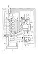
図1は本発明の第1の形態に係る制御装置が組み込まれた内燃機関の一例を示している。図1の内燃機関(以下、エンジンと称することがある。)1は、自動車などの車両に走行用動力源として搭載されるディーゼルエンジンであり、複数(図1では4つ)の気筒2が設けられる機関本体3と、各気筒2にそれぞれ接続される吸気通路4及び排気通路5とを備えている。吸気通路4には、吸気濾過用のエアフィルタ6、吸入空気量に対応した信号を出力するエアフローメータ7、吸入空気量を調整するための第1スロットル弁8、ターボ過給機9のコンプレッサ9a、吸気を冷却するためのインタークーラ10、及び吸入空気量を調整するための第2スロットル弁11が設けられている。排気通路5には、排気通路内に燃料を噴射するための燃料添加弁12、ターボ過給機9のタービン9b、排気を浄化するための排気浄化装置13、排気通路5の流路断面積を変更可能な排気絞り弁14、及び排気絞り弁14を迂回させて排気を下流に導くバイパス通路15が設けられている。
(First form)
FIG. 1 shows an example of an internal combustion engine in which a control device according to the first embodiment of the present invention is incorporated. An internal combustion engine (hereinafter sometimes referred to as an engine) 1 in FIG. 1 is a diesel engine mounted as a driving power source in a vehicle such as an automobile, and a plurality (four in FIG. 1) of cylinders 2 are provided. And an intake passage 4 and an
バイパス通路15には、排気絞り弁14と排気浄化装置13との間の排気通路内の圧力が所定圧以上になると開弁する圧力調整弁16が設けられている。排気浄化装置13には、三元触媒13a及び排気中の粒子状物質を捕集する排気浄化手段としてのパティキュレートフィルタ(以下、フィルタと略称することがある。)13bが設けられる。図1に示したように燃料添加弁12は、排気浄化装置13よりも上流に設けられる。排気絞り弁14は、その開度を閉じ側に制御することによって排気通路5の流路断面積を絞ることができ、全閉状態においても排気通路5が完全に遮断されないように全閉時の開度が設定される周知のものである。図1に示したように各気筒2には、気筒2内に燃料を噴射するためのインジェクタ17がそれぞれ設けられている。各インジェクタ17は、インジェクタ17に供給される高圧の燃料が蓄えられるコモンレール18に接続されている。また、エンジン1は機関本体3で発生したブローバイガスを吸気通路4に導くブローバイガス通路19を備えている。
The
排気通路5と吸気通路4とは、第1EGR通路としての高圧EGR通路20及び第2EGR通路としての低圧EGR通路21にて接続されている。図1に示したように高圧EGR通路20は、排気浄化装置13より上流の排気通路5とコンプレッサ9aより下流の吸気通路4とを接続している。低圧EGR通路21は、排気浄化装置13及び排気絞り弁14より下流の排気通路5とコンプレッサ9aより上流の吸気通路4とを接続している。そのため、排気絞り弁14は、排気浄化装置13より下流、かつ低圧EGR通路21の接続位置より上流の排気通路5に配置される。高圧EGR通路20には、高圧EGR通路20を介して吸気通路4に還流されるEGRガス(以下、第1EGRガスと称することがある。)の流量を調整する第1EGR弁としての高圧EGR弁22が設けられている。低圧EGR通路21には、EGRガスを冷却するためのEGRクーラ23、及び低圧EGR通路21を介して吸気通路4に還流されるEGRガス(以下、第2EGRガスと称することがある。)の流量を調整する第2EGR弁としての低圧EGR弁24が設けられている。このように低圧EGR通路21にはEGRクーラ23を設けるため、高圧EGR通路20よりも長さが長くなる。
The
高圧EGR弁22、低圧EGR弁24、燃料添加弁12、及び排気絞り弁14のそれぞれの動作は、エンジンコントロールユニット(ECU)30にて制御される。ECU30は、マイクロプロセッサ及びその動作に必要なROM、RAM等の周辺機器を含んだコンピュータとして構成され、エンジン1に設けられている各種センサからの出力信号を参照してエンジン1の運転状態を制御する周知のコンピュータユニットである。ECU30は、例えばエンジン1の運転状態に基づいて各気筒2に供給すべき燃料量を算出し、その算出した燃料量の燃料が各気筒2に供給されるように各気筒2に設けられたインジェクタ17の動作を制御する。ECU30には、各種センサとしてエンジン1の機関回転速度(回転数)に対応する信号を出力するクランク角センサ31、排気浄化装置13の前後の圧力差に対応する信号を出力する差圧センサ32、及び排気浄化装置13内の排気の圧力に対応する信号を出力する圧力センサ33が接続されている。また、エアフローメータ7もECU30に接続されている。
The operations of the high
ECU30は、エンジン1の回転数及び負荷に基づいてエンジン1の燃焼形態を、通常燃焼と予混合燃焼(以下、Homogeneous Charge Compression Ignition(HCCI)燃焼と称することがある。)とに切り替える。通常燃焼では、圧縮上死点においてインジェクタ17から気筒2内に燃料を噴射させ、その直後に燃料を燃焼させる。一方、予混合燃焼では、圧縮上死点の30°CA(クランク角度を意味する。)程度前頃にインジェクタ17から気筒2内に燃料を噴射させ、その後圧縮上死点でその燃料を燃焼させる。この予混合燃焼時は、気筒2内への新気の流入を抑制しつつEGRガスを大量に導入するため、ECU30は各スロットル弁8、11の開度をそれぞれ小さく設定するとともに各EGR弁22、24の開度をそれぞれ大きく設定する。このような燃焼形態の切り替えは、例えば図2に示したマップを予め実験などにより求めてECU30のROMに記憶させておき、このマップを参照して行えばよい。このように燃焼形態を切り替えることにより、ECU30が本発明の燃焼形態切替手段として機能する。
The
また、エンジン1では、排気通路4から吸気通路3に排気を還流させるための複数種類のEGRモードがエンジン1の運転状態に対応付けられて設定されている。EGRモードとしては、低圧EGR通路21のみを介して排気を吸気通路4に還流するロープレッシャーループ(LPL)モード、高圧EGR通路20のみを介して排気を吸気通路4に還流するハイプレッシャーループ(HPL)モード、及び高圧EGR通路20と低圧EGR通路21との両方のEGR通路を介して排気を吸気通路4に還流するMPLモードが設定されている。図3は、これら各EGRモードとエンジン1の運転状態との対応関係の一例を示す図である。ECU30は、吸気通路4への排気の還流を行う場合、図3の対応関係を参照し、エンジン1の運転状態を示す回転数及び負荷に応じてLPLモード、MPLモード、又はHPLモードのいずれかのEGRモードを選択する。また、エンジン1の運転状態の変化に応じてEGRモードを切り替える。なお、LPLモードは、高圧EGR弁22が全閉に維持されるとともに低圧EGR弁24が開けられることにより実行される。HPLモードは、低圧EGR弁24が全閉に維持されるとともに高圧EGR弁22が開けられることにより実行される。MPLモードは、高圧EGR弁22及び低圧EGR弁24の両方が開けられることにより実行される。これら各EGRモードにおける高圧EGR弁22及び低圧EGR弁24のそれぞれの開度は、エンジン1の運転状態に応じてECU30が適切な値に調整する。
In the
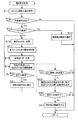
周知のようにフィルタ13bで捕集可能な粒子状物質の量には上限があり、所定の周期でフィルタ13bを粒子状物質が酸化除去される温度(例えば、600°C)まで昇温する昇温操作を実行してフィルタ13に捕集されている粒子状物質を酸化除去するPM再生を実行する必要がある。そこで、ECU30は、フィルタ13bのPM再生を実行すべくエンジン1の運転中に図4に示した機能再生制御ルーチンを所定の周期で繰り返し実行する。なお、図4の制御ルーチンはECU30が実行する他のルーチンと並行に実行される。
As is well known, there is an upper limit on the amount of particulate matter that can be collected by the
図4の制御ルーチンにおいてECU30は、まずステップS11においてエンジン1の運転状態を取得する。エンジン1の運転状態としては、エンジン1の回転数、吸入空気量、排気浄化装置13の前後の圧力差、及びエンジン1の燃焼形態などが取得される。次のステップS12においてECU30は、フィルタ13bのPM再生を実行する所定の再生条件が成立したか否か判断する。所定の再生条件は、フィルタ13bに捕集されている粒子状物質の量が予め設定した所定量を超えた場合に成立したと判断される。周知のように排気浄化装置13の前後の圧力差とフィルタ13bに捕集されている粒子状物質の量とは相関関係を有している。そこで、例えば排気浄化装置13の前後の圧力差が所定量に対応する許容上限値より大きい場合に所定の再生条件が成立したと判断される。また、排気浄化装置13に単位時間当たりに流入した粒子状物質の量を積算してフィルタ13bに捕集されている粒子状物質の量を推定し、その推定値が所定量を超えた場合に再生条件が成立したと判断してもよい。なお、フィルタ13bにて捕集可能な粒子状物質の上限はフィルタ13bの大きさに応じて変化するため、所定量及び許容上限値はフィルタ13bの大きさに応じて適宜設定すればよい。所定の再生条件が不成立と判断した場合は今回の制御ルーチンを終了する。
In the control routine of FIG. 4, the
一方、所定の再生条件が成立したと判断した場合はステップS13に進み、ECU30はエンジン1の燃焼形態がHCCI燃焼、すなわち予混合燃焼か否か判断する。エンジン1の燃焼形態が通常燃焼であると判断した場合はステップS14に進み、ECU30は各スロットル弁8、11を開き側に制御するとともに各EGR弁22、24を全閉にし、その後燃料添加弁12から燃焼を噴射させてフィルタ13bのPM再生を行う通常再生制御を実行する。その後、今回の制御ルーチンを終了する。
On the other hand, if it is determined that the predetermined regeneration condition is satisfied, the process proceeds to step S13, and the
一方、エンジン1の燃焼形態がHCCI燃焼であると判断した場合はステップS15に進み、ECU30は高圧EGR弁22が開いているか否か、すなわち高圧EGR通路20を介して排気を吸気通路4に還流しているか否か判断する。高圧EGR弁22が開いていると判断した場合はステップS16に進み、ECU30は高圧EGR弁22を全閉にする。続くステップS17においてECU30は、各スロットル弁8、11を所定の開度分開き側に制御する。所定の開度は、各気筒2に流入する新気の流量が急に増加しないように適宜設定すればよい。次のステップS18においてECU30は、高圧EGR弁22を全閉にしたことによる第1EGRガス量の減少を第2EGRガス量の増加で補償すべく低圧EGR弁24を開き側に制御する。このように第2EGRガス量を調整することにより、エンジン1の各気筒2に吸入される吸気の酸素濃度をHCCI燃焼の目標濃度範囲内に調整できる。その後ステップS19に進み、ECU30は排気絞り弁14を全閉にする。なお、既に排気絞り弁14が全閉であった場合はその状態を維持する。
On the other hand, if it is determined that the combustion mode of the
次のステップS20においてECU30は、エンジン1の背圧が所定の閾値以上か否か判断する。エンジン1の背圧(以下、背圧と略称することがある。)を高くすることによりエンジン1の負荷を高くして排気の温度を上昇させることができる。そこで、所定の閾値としては、例えば燃料添加弁12から噴射すべき燃料を減少させることができ、かつフィルタ13bの温度を速やかに上昇させることが可能な排気温度となる背圧が設定される。このような圧力はフィルタ13bの大きさに応じて異なるため、所定の閾値はフィルタ13bの大きさに応じて適宜設定してよい。なお、背圧は圧力センサ33にて検出してもよいし、高圧EGR弁22の開度、排気絞り弁14の開度、各スロットル弁8、11のそれぞれの開度、吸入空気量、及びインジェクタ17から噴射された燃料量に基づいて推定してもよい。背圧が閾値未満と判断した場合はステップS17に処理を戻し、背圧が所定の閾値以上に変化するまでステップS17〜S20の処理が繰り返し実行される。
In the next step S20, the
一方、背圧が所定の閾値以上と判断した場合はステップS21に進み、ECU30は燃料添加弁12から燃料を噴射させてフィルタ13bのPM再生を実行する燃料添加制御を実行する。その後、今回の制御ルーチンを終了する。なお、この燃料添加制御の実行時、ECU30は第1EGRガスの流量、第2EGRガスの流量、エンジン1の回転数、及びエンジン1の負荷に応じてエンジン1の燃焼形態を適宜変更してよい。例えば、第2EGRガスにてHCCI燃焼を継続可能であれば、HCCI燃焼を継続する。一方、第2EGRガスのみではHCCI燃焼が継続不可能と判断した場合はエンジン1の燃焼を通常燃焼に切り替えてもよい。
On the other hand, if it is determined that the back pressure is equal to or greater than the predetermined threshold value, the process proceeds to step S21, where the
ステップS15において高圧EGR弁22が閉じていると判断した場合はステップS22に進み、ECU30は各スロットル弁8、11を所定の開度分開き側に制御する。この所定の開度は上述したステップS17の処理と同様に設定される。続くステップS23においてECU30は、排気絞り弁14を全閉にする。なお、既に排気絞り弁14が全閉であった場合はその状態を維持する。次のステップS24においてECU30は各インジェクタ17からの燃料の噴射時期が圧縮上死点に近付くように噴射時期を遅角させる。その後ステップS25に進み、ECU30は上述したステップS20と同様に背圧が所定の閾値以上か否か判断する。背圧が所定の閾値未満と判断した場合はステップS22に処理を戻し、背圧が所定の閾値以上に変化するまでステップS22〜S25の処理が繰り返し実行される。一方、背圧が所定の閾値以上と判断した場合はステップS21に進み、ECU30は燃料添加制御を実行する。その後、今回の制御ルーチンを終了する。
When it is determined in step S15 that the high
図5は、図4の機能再生制御ルーチンによってエンジン1の燃焼形態がHCCI燃焼のときにフィルタ13bのPM再生を実行した場合の高圧EGR弁22の開度、排気絞り弁14の開度、背圧、吸入空気量、及び気筒2に流入する吸気の酸素濃度の時間変化を示している。図5の時刻T1において所定の再生条件が成立すると、まず高圧EGR弁22が全閉になるまで徐々に閉じ側に制御される。また、排気絞り弁14が全閉になるまで徐々に閉じ側に制御される。図5に示したように、このように高圧EGR弁22及び排気絞り弁14が閉じ側に制御されると、背圧が徐々に上昇する。一方、酸素濃度及び吸入空気量は、図4のステップS17が実行されて各スロットル弁8、11が開き側に制御されることにより一旦上昇するが、その後上昇が抑制されて所定値に安定する。図5の時刻T2において背圧が所定の閾値以上になると燃料添加弁12からの燃料の噴射が開始されるが、第2EGRガスの流量を増加させるので、酸素濃度及び吸入空気量を時刻T2における値のまま推移させることができる。第2EGRガスによる酸素濃度及び吸入空気量の増加の抑制が困難になり、これらの値が上昇を開始すると図5の時刻T3においてECU30はエンジン1の燃焼形態をHCCI燃焼から通常燃焼に切り替える。
FIG. 5 shows the opening degree of the high
以上に説明したように、第1の形態に係る制御装置によれば、エンジン1の燃焼形態がHCCI燃焼のときに所定の再生条件が成立した場合、背圧が所定の閾値以上に変化した後に燃料添加弁12から燃料を噴射させるので、エンジン1の燃焼形態がHCCI燃焼のときでもフィルタ13bのPM再生を適切に実行することができる。また、PM再生を実行する際は、各スロットル弁8、11を開き側に制御するので、速やかに背圧を上昇させることができる。さらに、低圧EGR弁24にて吸気通路4に還流されるEGRガスの流量を調整することにより、気筒2に吸入される吸気の酸素濃度を抑えることができる。そのため、NOxの発生を抑制しつつPM再生を実行することができる。
As described above, according to the control device according to the first embodiment, after the back pressure changes to a predetermined threshold or more when the predetermined regeneration condition is satisfied when the combustion mode of the
なお、ECU30は、図4のステップS16及びS19を実行することにより本発明の圧力上昇手段として、図4のステップS20を実行することにより本発明の判定手段として、図4のステップS21を実行することにより本発明の燃料添加手段としてそれぞれ機能する。また、ECU30は、図4のステップS18を実行することにより本発明の弁開度調整手段として機能する。
The
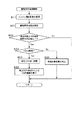
図4の制御ルーチンにおいては、エンジン1の燃焼形態がHCCI燃焼のときにPM再生を実行する場合、高圧EGR弁22を全閉に制御するが、この高圧EGR弁22を全閉にする制御を予め行っておくことにより、さらに速やかにPM再生を実行することができる。図6は、このように高圧EGR弁22を所定の再生条件が成立する前に予め全閉に制御するためにECU30がエンジン1の運転中に所定の周期で繰り返し実行する機能再生準備制御ルーチンを示している。なお、図6において図4と同一の処理には同一の参照符号を付して説明を省略する。
In the control routine of FIG. 4, when PM regeneration is executed when the combustion mode of the
図6の制御ルーチンにおいてECU30は、まずステップS11でエンジン1の運転状態を取得する。続くステップS31においてECU30は、フィルタ13bのPM再生を実行する機能再生時期を推定する。機能再生時期の推定は、例えば以下の推定方法にて行う。まず、エンジン1の運転状態に基づいて単位時間当たりに排気浄化装置13に流入する粒子状物質の量を算出する。次に排気浄化装置13に流入した粒子状物質の量の積算値と再生条件が成立する条件として設定された所定量との差を求める。その後、この積算値と所定量との差を単位時間当たりに排気浄化装置13に流入する粒子状物質の量で割ることにより機能再生時期を推定する。この処理を実行することにより、ECU30が本発明の残余期間推定手段として機能する。
In the control routine of FIG. 6, the
次のステップS32においてECU30は、機能再生時期までの残余期間が予め設定した判定値以下か否か判断する。判定値としては、例えばエンジン1の運転状態に影響を与えることなく第1EGRガスの還流を停止させることが可能な時間が設定される。残余期間が判定値より大きいと判断した場合は今回の制御ルーチンを終了する。一方、残余期間が判定値以下と判断した場合はステップS33に進み、ECU30はエンジン1の燃焼形態がHCCI燃焼か否か判断する。エンジン1の燃焼形態が通常燃焼であると判断した場合はステップS34に進み、ECU30は所定の再生条件が成立するまでエンジン1の燃焼形態を変更することを禁止する。所定の再生条件が成立するまで、エンジン1の燃焼形態は通常燃焼に維持される。その後、今回の制御ルーチンを終了する。
In the next step S32, the
一方、エンジン1の燃焼状態がHCCI燃焼であると判断した場合はステップS35に進み、ECU30は高圧EGR弁22を全閉にする。なお、既に高圧EGR弁22が全閉であった場合はその状態を維持する。続くステップS36においてECU30は、高圧EGR弁22を制御したことによる第1EGRガスの減少が第2EGRガスの増加によって補償されるように低圧EGR弁24の開度を制御する。また、以降は所定の再生条件が成立するまで低圧EGR通路21のみを介して吸気通路4にEGRガスが還流されるようにEGRモードをLPLモードに固定する。この処理を実行することにより、ECU30が本発明の第1EGR弁停止手段として機能する。その後、今回の制御ルーチンを終了する。
On the other hand, when it is determined that the combustion state of the
図6の制御ルーチンを実行することにより、所定の再生条件が成立する前に予め高圧EGR弁22を全閉にしておくことができるので、所定の再生条件が成立したときに排気絞り弁14を全閉にすることで速やかに背圧を上昇させることができる。そのため、フィルタ13bのPM再生を速やかに実行することができる。
By executing the control routine of FIG. 6, the high
(第2の形態)
次に図7及び図8を参照して本発明の第2の形態について説明する。なお、この形態でもエンジン1については図1が参照される。図7は、第2の形態における機能再生制御ルーチンを示している。図7の制御ルーチンもECU30が実行する他のルーチンとエンジン1の運転中に並行に所定の周期で繰り返し実行される。なお、図7において図4と同一の処理には同一の参照符号を付して説明を省略する。
(Second form)
Next, a second embodiment of the present invention will be described with reference to FIGS. In this embodiment, FIG. 1 is referred to for the
図7においてECU30は、ステップS13まで図4と同様に処理を進める。ステップS13においてエンジン1の燃焼形態が通常燃焼と判断した場合、ECU30はステップS14を実行し、その後今回の制御ルーチンを終了する。一方、エンジン1の燃焼形態がHCCI燃焼と判断した場合はステップS16に進み、高圧EGR弁22を全閉にする。続くステップS17においてECU30は各スロットル弁8、11を所定の開度分開き側に制御し、その後ステップS19においてECU30は排気絞り弁14を全閉にする。そして、ステップS18においてECU30は、高圧EGR弁22を全閉にしたことによる第1EGRガス量の減少を第2EGRガス量の増加で補償すべく低圧EGR弁24を開き側に制御する。次のステップS20においてECU30は、背圧が所定の閾値以上か否か判断する。背圧が所定の閾値未満と判断した場合はステップS16に処理を戻し、背圧が所定の閾値以上に変化するまでステップS16〜S20の処理を繰り返し実行する。一方、背圧が所定の閾値以上と判断した場合はステップS21に進み、ECU20は燃料添加制御を実行する。
In FIG. 7, the
続くステップS41においてECU30は、第1EGRガスの二酸化酸素(CO2)の濃度が所定の許容値以下か否か判断する。燃料添加弁12から噴射された燃料はフィルタ13bで燃焼しCO2が発生する。また、フィルタ13bに捕集されていた粒子状物質が燃焼する際にもCO2が発生する。この発生したCO2は第2EGRガスとして吸気通路4に還流されるが、この際CO2の濃度が高すぎるとエンジン1の燃焼状態が悪化してトルク変動が発生するおそれがある。そこで、許容値としては、EGRガスとして還流されてもエンジン1のトルク変動の発生を抑制することが可能なCO2濃度が設定される。第1EGRガスのCO2濃度は、例えばインジェクタ17から噴射された燃料量、吸入空気量、燃料添加弁12から噴射された燃料量、及びエンジン1から排出された排気のうち排気第1EGRガスとして吸気通路4に還流される排気の割合を示すLPLEGR率などに基づいて推定すればよい。このように第1EGRガスのCO2濃度を推定することにより、ECU30が本発明の二酸化炭素濃度取得手段として機能する。第1EGRガスのCO2濃度が許容値以下と判断した場合は、今回の制御ルーチンを終了する。
In subsequent step S41, the
一方、第1EGRガスのCO2濃度が許容値より大きいと判断した場合はステップS42に進み、ECU30は高圧EGR弁22を開き側に制御するとともに、その制御による第1EGRガスの増加が第2EGRガスの減少によって補償されるように低圧EGR弁24を閉じ側に制御する。この処理を実行することにより、ECU30が本発明の排気流量制御手段として機能する。続くステップS43においてECU30は、背圧が所定の許容圧力以上か否か判断する。高圧EGR弁22を開き側に制御するとエンジン1の背圧が低下し、これによりエンジン1への負荷が低下して排気の温度が低下する。この場合、フィルタ13bのPM再生を継続させるためには燃料添加弁12からより多くの燃料を噴射させる必要がある。そのため、背圧にはPM再生を適切に実行可能な圧力範囲が存在する。そこで、所定の許容圧力としては、例えばこの圧力範囲の下限値が設定される。背圧が所定の許容圧力以上と判断した場合は、今回の制御ルーチンを終了する。一方、背圧が所定の許容圧力未満と判断した場合はステップS44に進み、ECU30は燃料添加弁12からの燃料の噴射を停止させて燃料添加制御を中止させる。この処理を実行することにより、ECU30が本発明の中止手段として機能する。その後、今回の制御ルーチンを終了する。
On the other hand, if it is determined that the CO 2 concentration of the first EGR gas is greater than the allowable value, the process proceeds to step S42, where the
第2の形態では、第2EGRガスのCO2濃度が所定の許容値より大きくなると高圧EGR弁22を開き側に制御するとともに低圧EGR弁24を閉じ側に制御するので、エンジン1のトルク変動を抑制しつつ吸気通路4にEGRガスを還流し続けてエンジン1の燃焼形態をHCCI燃焼に維持することができる。また、エンジン1の背圧が許容圧力未満に低下すると燃料添加制御を中止するので、燃料添加弁12からの無駄な燃料の噴射を防止できる。
In the second mode, when the CO 2 concentration of the second EGR gas becomes larger than a predetermined allowable value, the high
なお、第2の形態においては、図7のステップS16において高圧EGR弁22を全閉にするとともに低圧EGR弁24も全閉にし、エンジン1の燃焼形態をHCCI燃焼から通常燃焼に切り替えてもよい。このようにエンジン1の燃焼形態を切り替えることにより、ECU30が本発明の強制切替手段として機能する。フィルタ13bのPM再生時にエンジン1の燃焼形態をHCCI燃焼から通常燃焼に切り替える場合、高圧EGR弁22と低圧EGR弁24を同時に全閉にしても高圧EGR通路20より低圧EGR通路21の方が長いため、高圧EGR通路20を介した排気の還流が停止してから低圧EGR通路21を介した排気の還流が停止するまでに無駄な時間差が生じる。そこで、このようにフィルタ13bのPM再生時にエンジン1の燃焼形態をHCCI燃焼から通常燃焼に切り替える場合は、所定の再生条件が成立する前に予め低圧EGR弁24を全閉にし、高圧EGR通路20のみを使用した排気の還流を行ってもよい。図8は、このように所定の再生条件が成立する前に予め低圧EGR弁24を全閉にするべくECU30がエンジン1の運転中に所定の周期で繰り返し実行する機能再生準備制御ルーチンを示している。なお、図8において図6と同一の処理には同一の参照符号を付して説明を省略する。
In the second mode, the high
図8の制御ルーチンにおいてECU30はステップS33まで図6の制御ルーチンと同様に処理を進める。ステップS33においてエンジン1の燃焼形態が通常燃焼と判断した場合はステップS34に進み、ECU30は所定の再生条件が成立するまでエンジン1の燃焼形態を変更することを禁止する。その後、今回の制御ルーチンを終了する。一方、エンジン1の燃焼形態がHCCI燃焼と判断した場合はステップS51に進み、ECU30は低圧EGR弁24を全閉にする。なお、既に低圧EGR弁24が全閉であった場合はその状態を維持する。続くステップS52においてECU30は、低圧EGR弁22を制御したことによる第2EGRガスの減少が第1EGRガスの増加によって補償されるように高圧EGR弁22の開度を制御する。また、以降は所定の再生条件が成立するまで高圧EGR通路20のみを介して吸気通路4にEGRガスが還流されるようにEGRモードをHPLモードに固定する。この処理を実行することにより、ECU30が本発明の第2EGR弁停止手段として機能する。その後、今回の制御ルーチンを終了する。
In the control routine of FIG. 8, the
このように所定の再生条件が成立する前に予め低圧EGR弁24を全閉にしておくことにより、所定の再生条件の成立時にエンジン1の燃焼形態を速やかに通常燃焼に切り替えうることができる。そのため、フィルタ13bのPM再生を速やかに実行することができる。
Thus, by fully closing the low
本発明は、上述した各形態に限定されることなく、種々の形態にて実施することができる。例えば、本発明の制御装置が適用される内燃機関の排気浄化手段は、パティキュレートフィルタに限定されない。パティキュレートフィルタに吸蔵還元型NOx触媒物質を担持させたものが排気浄化手段として設けられていてもよいし、担体に吸蔵還元型NOx触媒を担持させた排気浄化触媒が排気浄化手段として設けられていてもよい。周知のように吸蔵還元型NOx触媒は排気に含まれる硫黄酸化物(SOx)に被毒されるため、NOx触媒から硫黄(S)成分を放出させるべくNOx触媒の昇温操作を含んだ機能再生処理、いわゆるS再生がNOx触媒に対して所定の間隔で行われる。そのため、エンジンの燃焼形態がHCCI燃焼のときにS再生が実行される場合がある。そこで、本発明の制御装置を適用する。これにより、エンジンの燃焼形態がHCCI燃焼のときでもS再生を適切に実行することができる。 This invention is not limited to each form mentioned above, It can implement with a various form. For example, the exhaust gas purification means of the internal combustion engine to which the control device of the present invention is applied is not limited to the particulate filter. A particulate filter carrying a storage reduction type NOx catalyst material may be provided as exhaust purification means, or an exhaust purification catalyst having a carrier carrying a storage reduction type NOx catalyst is provided as exhaust purification means. May be. As is well known, the NOx storage reduction catalyst is poisoned by sulfur oxide (SOx) contained in the exhaust gas, so that the function regeneration including the temperature raising operation of the NOx catalyst is performed to release the sulfur (S) component from the NOx catalyst. Processing, so-called S regeneration, is performed at predetermined intervals with respect to the NOx catalyst. Therefore, S regeneration may be performed when the combustion mode of the engine is HCCI combustion. Therefore, the control device of the present invention is applied. Thereby, S regeneration can be appropriately executed even when the combustion mode of the engine is HCCI combustion.
なお、吸蔵還元型のNOx触媒は、NOxを触媒にて保持できるものであればよく、吸収又は吸着いずれの態様でNOxが保持されるかは吸蔵の用語によって制限されない。SOxの被毒についてもその態様を問わないものである。 The NOx storage reduction catalyst may be any catalyst that can hold NOx in the catalyst, and whether it is absorbed or adsorbed is not limited by the term of storage. The aspect of SOx poisoning is not limited.
1 内燃機関
2 気筒
4 吸気通路
5 排気通路
8 第1スロットル弁
11 第2スロットル弁
12 燃料添加弁
13b パティキュレートフィルタ(排気浄化手段)
14 排気絞り弁
20 高圧EGR通路(第1EGR通路)
21 低圧EGR通路(第2EGR通路)
22 高圧EGR弁(第1EGE弁)
24 低圧EGR弁(第2EGR弁)
30 エンジンコントロールユニット(燃焼形態切替手段、圧力上昇手段、判定手段、燃料添加手段、弁開度調整手段、残余期間推定手段、第1EGR弁停止手段、二酸化炭素濃度取得手段、排気流量制御手段、中止手段、強制切替手段、第2EGR弁停止手段)
DESCRIPTION OF
14
21 Low pressure EGR passage (second EGR passage)
22 High pressure EGR valve (1st EGE valve)
24 Low pressure EGR valve (2nd EGR valve)
30 Engine control unit (combustion mode switching means, pressure increase means, determination means, fuel addition means, valve opening adjustment means, remaining period estimation means, first EGR valve stop means, carbon dioxide concentration acquisition means, exhaust flow rate control means, stop Means, forced switching means, second EGR valve stop means)
Claims (5)
前記内燃機関の燃焼形態が前記予混合燃焼であり、かつ前記排気浄化手段の昇温操作を実行する所定の再生条件が成立した場合、前記内燃機関の排気通路の流路断面積が絞られるように前記排気絞り弁を制御するとともに前記第1EGR通路を介した前記吸気通路への排気の還流が停止されるように前記第1EGR弁の開度を制御する圧力上昇制御を実行する圧力上昇手段と、前記圧力上昇手段による前記圧力上昇制御の実行後に前記内燃機関の背圧が所定の閾値以上に変化したか否か判定する判定手段と、前記判定手段により前記内燃機関の背圧が前記所定の閾値以上に変化したと判定された場合に前記燃料添加弁から燃料を噴射させる機能再生制御を実行する燃料添加手段と、を備えることを特徴とする内燃機関の制御装置。 A regenerative exhaust purification means that is provided in the exhaust passage and regenerates its function by a temperature raising operation, a fuel addition valve that injects fuel into the exhaust passage upstream of the exhaust purification means, and an exhaust upstream of the exhaust purification means A first EGR passage communicating the passage and the intake passage, a first EGR valve for adjusting a flow rate of exhaust gas recirculated to the intake passage through the first EGR passage, an exhaust passage downstream of the exhaust purification means, and the intake air A second EGR passage communicating with the passage, a second EGR valve for adjusting a flow rate of exhaust gas recirculated to the intake passage via the second EGR passage, and a connection position of the second EGR passage downstream from the exhaust purification unit The present invention is applied to a compression ignition type internal combustion engine having an exhaust throttle valve that is arranged in an upstream exhaust passage and capable of changing the cross-sectional area of the exhaust passage, and is adapted to the operating state of the internal combustion engine. The control apparatus for an internal combustion engine having a combustion mode switching means for switching the combustion mode to the normal combustion and premixed combustion Te,
When the combustion mode of the internal combustion engine is the premixed combustion and a predetermined regeneration condition for executing the temperature raising operation of the exhaust purification means is satisfied, the flow passage cross-sectional area of the exhaust passage of the internal combustion engine is reduced. Pressure increasing means for controlling the exhaust throttle valve and performing pressure increase control for controlling the opening degree of the first EGR valve so that the exhaust gas recirculation to the intake passage through the first EGR passage is stopped. Determining means for determining whether or not the back pressure of the internal combustion engine has changed to a predetermined threshold value or more after execution of the pressure increase control by the pressure increasing means; and determining the back pressure of the internal combustion engine by the determining means. A control device for an internal combustion engine, comprising: fuel addition means for executing function regeneration control for injecting fuel from the fuel addition valve when it is determined that the fuel consumption has changed to a threshold value or more.
Priority Applications (1)
| Application Number | Priority Date | Filing Date | Title |
|---|---|---|---|
| JP2007175337A JP4748124B2 (en) | 2007-07-03 | 2007-07-03 | Control device for internal combustion engine |
Applications Claiming Priority (1)
| Application Number | Priority Date | Filing Date | Title |
|---|---|---|---|
| JP2007175337A JP4748124B2 (en) | 2007-07-03 | 2007-07-03 | Control device for internal combustion engine |
Publications (3)
| Publication Number | Publication Date |
|---|---|
| JP2009013839A JP2009013839A (en) | 2009-01-22 |
| JP2009013839A5 JP2009013839A5 (en) | 2010-01-21 |
| JP4748124B2 true JP4748124B2 (en) | 2011-08-17 |
Family
ID=40355044
Family Applications (1)
| Application Number | Title | Priority Date | Filing Date |
|---|---|---|---|
| JP2007175337A Expired - Fee Related JP4748124B2 (en) | 2007-07-03 | 2007-07-03 | Control device for internal combustion engine |
Country Status (1)
| Country | Link |
|---|---|
| JP (1) | JP4748124B2 (en) |
Families Citing this family (3)
| Publication number | Priority date | Publication date | Assignee | Title |
|---|---|---|---|---|
| JP5604912B2 (en) * | 2010-03-04 | 2014-10-15 | いすゞ自動車株式会社 | Automotive exhaust purification system |
| JP5822445B2 (en) * | 2010-08-06 | 2015-11-24 | ダイハツ工業株式会社 | Blowby gas recirculation system |
| JP5530338B2 (en) * | 2010-11-08 | 2014-06-25 | 本田技研工業株式会社 | Internal combustion engine system |
Family Cites Families (4)
| Publication number | Priority date | Publication date | Assignee | Title |
|---|---|---|---|---|
| JP3986208B2 (en) * | 1999-06-14 | 2007-10-03 | 日野自動車株式会社 | Exhaust gas purification device |
| JP4000987B2 (en) * | 2002-10-29 | 2007-10-31 | 三菱ふそうトラック・バス株式会社 | Compression ignition internal combustion engine |
| JP4001235B2 (en) * | 2003-03-20 | 2007-10-31 | 日野自動車株式会社 | Exhaust purification control method and exhaust purification apparatus |
| JP4561467B2 (en) * | 2005-05-16 | 2010-10-13 | いすゞ自動車株式会社 | Exhaust gas purification method and exhaust gas purification system |
-
2007
- 2007-07-03 JP JP2007175337A patent/JP4748124B2/en not_active Expired - Fee Related
Also Published As
| Publication number | Publication date |
|---|---|
| JP2009013839A (en) | 2009-01-22 |
Similar Documents
| Publication | Publication Date | Title |
|---|---|---|
| EP3103993B1 (en) | Control device for internal combustion engine | |
| US7021050B2 (en) | Engine exhaust particulate after-treatment system | |
| US8266898B2 (en) | Control apparatus for internal combustion engine | |
| US7993582B2 (en) | Sulfur purge control device for an internal combustion engine | |
| JP4670592B2 (en) | Exhaust gas recirculation system for internal combustion engines | |
| US20070056266A1 (en) | System and method for regenerating a NOx storage and conversion device | |
| US20170009676A1 (en) | Control device and control method for diesel engine | |
| JP2008138638A (en) | Exhaust recirculating device of internal combustion engine | |
| JP4748124B2 (en) | Control device for internal combustion engine | |
| US7950225B2 (en) | Exhaust control system for an internal combustion engine | |
| JP6278344B2 (en) | Engine exhaust purification system | |
| JP4941079B2 (en) | Exhaust gas recirculation control device for internal combustion engine | |
| JP2018096243A (en) | Device for controlling internal combustion engine | |
| JP5472082B2 (en) | Combustion mode control system for compression ignition internal combustion engine | |
| JP5240514B2 (en) | Engine exhaust gas recirculation system | |
| EP1887202B1 (en) | Sulfur purge control device for an internal combustion engine | |
| EP1384876B1 (en) | Exhausted particulate treatment device for an engine, engine, computer program product, computer-readable storage medium and exhausted particulate treatment method for an engine | |
| JP4500765B2 (en) | Exhaust gas purification device for internal combustion engine | |
| JP2009013872A (en) | Intake control device for internal combustion engine | |
| JP4872824B2 (en) | Exhaust gas recirculation device for internal combustion engine | |
| JP6270248B1 (en) | Engine exhaust purification system | |
| JP3807209B2 (en) | Operation control device for internal combustion engine | |
| JP5381116B2 (en) | Control device and control method for exhaust gas recirculation temperature of internal combustion engine | |
| JP2008138590A (en) | Exhaust emission control system of internal combustion engine | |
| JP4063743B2 (en) | Fuel injection timing control device for internal combustion engine |
Legal Events
| Date | Code | Title | Description |
|---|---|---|---|
| A521 | Written amendment |
Free format text: JAPANESE INTERMEDIATE CODE: A523 Effective date: 20091201 |
|
| A621 | Written request for application examination |
Free format text: JAPANESE INTERMEDIATE CODE: A621 Effective date: 20091201 |
|
| A977 | Report on retrieval |
Free format text: JAPANESE INTERMEDIATE CODE: A971007 Effective date: 20110330 |
|
| TRDD | Decision of grant or rejection written | ||
| A01 | Written decision to grant a patent or to grant a registration (utility model) |
Free format text: JAPANESE INTERMEDIATE CODE: A01 Effective date: 20110419 |
|
| A61 | First payment of annual fees (during grant procedure) |
Free format text: JAPANESE INTERMEDIATE CODE: A61 Effective date: 20110502 |
|
| R151 | Written notification of patent or utility model registration |
Ref document number: 4748124 Country of ref document: JP Free format text: JAPANESE INTERMEDIATE CODE: R151 |
|
| FPAY | Renewal fee payment (event date is renewal date of database) |
Free format text: PAYMENT UNTIL: 20140527 Year of fee payment: 3 |
|
| LAPS | Cancellation because of no payment of annual fees |