EP1437249A1 - Latching device for a vehicle roof - Google Patents
Latching device for a vehicle roof Download PDFInfo
- Publication number
- EP1437249A1 EP1437249A1 EP20030029349 EP03029349A EP1437249A1 EP 1437249 A1 EP1437249 A1 EP 1437249A1 EP 20030029349 EP20030029349 EP 20030029349 EP 03029349 A EP03029349 A EP 03029349A EP 1437249 A1 EP1437249 A1 EP 1437249A1
- Authority
- EP
- European Patent Office
- Prior art keywords
- convertible top
- locking hook
- lever
- top lock
- levers
- Prior art date
- Legal status (The legal status is an assumption and is not a legal conclusion. Google has not performed a legal analysis and makes no representation as to the accuracy of the status listed.)
- Granted
Links
- 229910000831 Steel Inorganic materials 0.000 abstract 1
- 239000010959 steel Substances 0.000 abstract 1
- 230000033001 locomotion Effects 0.000 description 11
- 230000005540 biological transmission Effects 0.000 description 2
- 230000002950 deficient Effects 0.000 description 2
- 206010044684 Trismus Diseases 0.000 description 1
- 230000015572 biosynthetic process Effects 0.000 description 1
- 238000010276 construction Methods 0.000 description 1
- 238000005553 drilling Methods 0.000 description 1
- 230000002349 favourable effect Effects 0.000 description 1
Images


Classifications
-
- B—PERFORMING OPERATIONS; TRANSPORTING
- B60—VEHICLES IN GENERAL
- B60J—WINDOWS, WINDSCREENS, NON-FIXED ROOFS, DOORS, OR SIMILAR DEVICES FOR VEHICLES; REMOVABLE EXTERNAL PROTECTIVE COVERINGS SPECIALLY ADAPTED FOR VEHICLES
- B60J7/00—Non-fixed roofs; Roofs with movable panels, e.g. rotary sunroofs
- B60J7/185—Locking arrangements
- B60J7/1851—Locking arrangements for locking the foldable soft- or hard-top to the windshield header
-
- Y—GENERAL TAGGING OF NEW TECHNOLOGICAL DEVELOPMENTS; GENERAL TAGGING OF CROSS-SECTIONAL TECHNOLOGIES SPANNING OVER SEVERAL SECTIONS OF THE IPC; TECHNICAL SUBJECTS COVERED BY FORMER USPC CROSS-REFERENCE ART COLLECTIONS [XRACs] AND DIGESTS
- Y10—TECHNICAL SUBJECTS COVERED BY FORMER USPC
- Y10T—TECHNICAL SUBJECTS COVERED BY FORMER US CLASSIFICATION
- Y10T292/00—Closure fasteners
- Y10T292/08—Bolts
- Y10T292/1043—Swinging
- Y10T292/1075—Operating means
- Y10T292/1082—Motor
Definitions
- the present invention relates to a convertible top lock of a vehicle a locking hook, which is preferably U-shaped in cross section - Link plate via guide means from a closed position to one Open position is arranged movably on a defined path, with a Gear motor is provided for pivoting a drive lever, which with the Lock hook is connected.
- Such a convertible top closure is described, for example, by DE 197 21 229 A1 known.
- Convertible top locks are used for automatic closing and Open the convertible top used.
- the well-known leadership of the Locking hook in the link plate enables a defined motor Movement of the locking hook with the help of the gear motor.
- the convertible top lock has a compact arrangement, making it space-saving Construction is achieved.
- the invention has for its object a motor-driven convertible top lock to develop with a compact space-saving design such that the Locking hook has a larger range of motion, so in the Open position a greater distance from the locking hook to Windshield frame is achieved.
- This task is accomplished by a top lock of the type mentioned solved, in which the connection of the locking hook with the drive lever through a plurality of articulated levers is formed.
- the locking hook is not directly connected to the drive lever, but rather over several levers of a toggle link connection, which accommodates space-saving can be. It will. nevertheless a defined power transmission to the Locking hook reached to close the roof under tension.
- the link plate has two in recesses extending essentially in the longitudinal direction of the locking hook for the formation of scenery tracks, one of which for guiding the Guide pin and their other for guiding and storing the guide pin at the end of the convertible top lock facing away from the windshield frame is provided.
- the use of two backdrop tracks ensures a precise Movement of the locking hook.
- the first lever is laterally outside of the Setting plate arranged and on the one hand with the locking hook and on the other another with the one also arranged laterally outside the backdrop plate second lever connected, the second lever in turn via the third lever is connected to the drive lever.
- the locking hook inside the Guide plate is guided, are the means for deflecting the locking hook arranged outside the backdrop plate. This has a favorable effect on the required space.
- the top lock of another embodiment is by two first and second levers, levers arranged on both sides of the link plate, the third lever between these levers above the Locking hook is arranged.
- Means for triggering the limit switch are in the Lever integrated and thus automatically coupled to the movement of the lever.
- the other elements of the limit switch for example the microswitches, are on a board housed, which carries all elements of the limit switch.
- the housing of the top lock an opening for manual actuation of the worm gear with a Tool includes.
- the worm gear can Have an internal hexagon hole, so that the worm gear with a Allen key can be easily driven.
- a convertible top of a passenger car can be closed by means of a convertible top lock 1 closed by the detachable attachment to a windshield frame become.
- the convertible top lock 1 comprises one on the Underside of rigid front hood frame 2, one in its locked position with a windshield frame in Operatively connected locking hook 3 and a geared motor 4 with a gear housing 5, 6 for moving the locking hook 3 from the Closed position in the open position or vice versa.
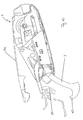
- Fig. 6 shows the on the Underside of the top frame to be attached to the top Convertible top lock 1.
- the convertible top lock 1 is used to lock the convertible top in Longitudinal direction of the passenger car against the windshield frame pulled and held in the cocked position. Via a carrier plate 7 the convertible top lock 1 can be fixed in place on the convertible top frame.
- the locking hook 3 is on its the windshield frame opposite end by means of a guide pin 8 and a guide pin 9 slidably mounted, which is used in the recesses of a link plate 10 are.
- the locking hook 3 can be deflected within the link plate 10 become.
- the design of the recesses creates a defined movement the locking hook 3 specified.
- the locking hook 3 is over first lever 11 and second triangular lever 12 and 12 arranged on both sides a third, centrally arranged lever 13 (axis 14) with a drive lever articulated, which controls the movement of the locking hook 3.
- the second Lever 12 is in turn rotatably supported via an axis 16.
- the drive lever 15 by means of a Geared motor 4 driven drive shaft moves, so that the hinged levers 11, 12 and 13 towards the windshield frame guided move and the locking hook 3 from the closed position down Guide away from the windshield frame to the open position.
- a switching bracket 17 is pivotally mounted (axis 16), which by a tension spring 18th is pulled down.
- a tension spring 18th is pulled down.
- the switching bracket 17 and the second lever 12 each have a shoulder 19 or 20, which each have a microswitch 22 arranged on a circuit board 21 or 23 can trigger to the geared motor 4 in the open position or in the Switch off the closed position. In an end position of the switching bracket 17 or Lever 12 strike the paragraphs 19, 20 on the microswitches 22, 23.
- the locking hook 3 is curved and over the cylinder pin 9 and the guide pin 8 in recesses 24 and 25 of the link plate 10 its movement, resulting in a movement on a defined path results.
- the drive lever 15 is rotatably mounted on the drive shaft 26 and connected in an articulated manner to the lever 13 via a cylindrical pin 13 '. Therefore judges the drive lever 15 on a counterclockwise rotation, pushes the first lever 13 and also the second lever 12 in the direction Windshield frame and takes the locking hook 3 with it.
- the geared motor 4 comprises a planetary gear (see planet carrier 27, Sun gear 28, planet gears 29, ring gear 30) and a worm gear 31 for Drive of the drive shaft 26, which is shown in FIGS. 3 and 5 can be seen.
- the worm gear 31 can be started with a tool.
- the Housing 2 has a flap or an opening to the tool with the To bring worm gear 31 into engagement.
- the worm gear activated in this way 31 leads to the rotation of the drive shaft 26, which consequently also in the case of a defective one Geared motor 4 can be driven to actuate the convertible top lock.
- Fig. 7 is the attachment of the support plate 7 to the convertible top frame remove. Bores 32 are used to hold fasteners Fitting the convertible top lock 1.
- the housing 2 of the convertible top lock 1 is not drawn in this illustration for the sake of clarity.
- housing 2 is the components of the Convertible top lock covering the interior of the passenger car.
- FIG. 9 shows the movement of the locking hook 3 along a curve 33 illustrated.
- the dashed frame 34 and Sections 35, 36, 37 and 38 of the windshield frame indicated.
- an actuation switch for the geared motor 4 is actuated so that the drive shaft 26 performs a counterclockwise rotation in the direction of rotation 39.
- the levers 11 and 12 pivot towards the windshield frame and the locking hook 3, which is also moved, moves along the curve 33 because the guide pin 8 and the guide pin 9 in slide tracks of Guide plate 10 are performed.
- a catch nose 40 moves away from section 36 of the windshield frame to the open position (see Fig. 10).
- the locking hook 3 is no longer on the windshield frame so that the convertible top. can be opened.
- To close the convertible top the locking hook 3 and the levers 11, 12 perform a movement and Swiveling in the opposite direction to the opening direction 41 because the Drive shaft 26 is driven clockwise.
Landscapes
- Engineering & Computer Science (AREA)
- Mechanical Engineering (AREA)
- Lock And Its Accessories (AREA)
- Power-Operated Mechanisms For Wings (AREA)
- Body Structure For Vehicles (AREA)
- Refuge Islands, Traffic Blockers, Or Guard Fence (AREA)
- Window Of Vehicle (AREA)
- Vehicle Interior And Exterior Ornaments, Soundproofing, And Insulation (AREA)
- Rear-View Mirror Devices That Are Mounted On The Exterior Of The Vehicle (AREA)
Abstract
Description
Die vorliegende Erfindung betrifft einen Verdeckverschluss eines Fahrzeugs mit einem Verschlusshaken, der in einem - im Querschnitt gesehen vorzugsweise U-förmigen - Kulissenblech über Führungsmittel aus einer Schließstellung in eine Offenstellung auf einer definierten Bahn beweglich angeordnet ist, wobei ein Getriebemotor zum Verschwenken eines Antriebshebel vorgesehen ist, der mit dem Verschlusshaken in Verbindung steht.The present invention relates to a convertible top lock of a vehicle a locking hook, which is preferably U-shaped in cross section - Link plate via guide means from a closed position to one Open position is arranged movably on a defined path, with a Gear motor is provided for pivoting a drive lever, which with the Lock hook is connected.
Ein derartiger Verdeckverschluss ist beispielsweise durch die DE 197 21 229 A1 bekannt geworden.Such a convertible top closure is described, for example, by DE 197 21 229 A1 known.
Verdeckverschlüsse mit Getriebemotor werden zum automatischen Schließen und Öffnen des Verdecks von Cabrios eingesetzt. Die bekannte Führung des Verschlusshakens in dem Kulissenblechs ermöglicht eine definierte motorische Bewegung des Verschlusshakens mit Hilfe des Getriebemotors. Der Verdeckverschluss weist eine kompakte Anordnung auf, damit eine platzsparende Bauweise erreicht wird.Convertible top locks are used for automatic closing and Open the convertible top used. The well-known leadership of the Locking hook in the link plate enables a defined motor Movement of the locking hook with the help of the gear motor. The The convertible top lock has a compact arrangement, making it space-saving Construction is achieved.
Der Erfindung liegt die Aufgabe zugrunde, einen motorgetrieben Verdeckverschluss mit einer kompakten platzsparenden Bauweise derart weiterzubilden, dass der Verschlusshaken einen größeren Bewegungsradius besitzt, damit in der Offenstellung ein größerer Abstand des Verschlusshakens zum Windschutzscheibenrahmen erzielt wird. The invention has for its object a motor-driven convertible top lock to develop with a compact space-saving design such that the Locking hook has a larger range of motion, so in the Open position a greater distance from the locking hook to Windshield frame is achieved.
Diese Aufgabe wird durch einen Verdeckverschluss der eingangs genannten Art gelöst, bei dem die Verbindung des Verschlusshakens mit dem Antriebshebel durch mehrere gelenkig miteinander verbundene Hebel ausgebildet ist. Der Verschlusshaken ist nicht unmittelbar mit dem Antriebshebel verbunden, sondern über mehrere Hebel einer Kniehebel-Verbindung, die platzsparend untergebracht werden können. Es wird. dennoch eine definierte Kraftübertragung auf den Verschlusshaken erreicht, um das Verdeck unter Spannung zu schließen.This task is accomplished by a top lock of the type mentioned solved, in which the connection of the locking hook with the drive lever through a plurality of articulated levers is formed. The The locking hook is not directly connected to the drive lever, but rather over several levers of a toggle link connection, which accommodates space-saving can be. It will. nevertheless a defined power transmission to the Locking hook reached to close the roof under tension.
In weiterer Ausgestaltung der Erfindung weist das Kulissenblech zwei sich im wesentlichen in Längsrichtung des Verschlusshakens erstreckende Ausnehmungen zur Ausbildung von Kulissenbahnen auf, deren eine zur Führung des Führungsstiftes und deren andere zur Führung und Lagerung des Führungsbolzens am dem Windschutzscheibenrahmen abgewandten Ende des Verdeckverschlusses vorgesehen ist. Die Verwendung zweier Kulissenbahnen sorgt für eine präzise Bewegung des Verschlusshakens.In a further embodiment of the invention, the link plate has two in recesses extending essentially in the longitudinal direction of the locking hook for the formation of scenery tracks, one of which for guiding the Guide pin and their other for guiding and storing the guide pin at the end of the convertible top lock facing away from the windshield frame is provided. The use of two backdrop tracks ensures a precise Movement of the locking hook.
Bei einer bevorzugten Ausführung ist der erste Hebel seitlich außerhalb des Kulissenblechs angeordnet und zum einen mit dem Verschlusshaken und zum anderen mit dem ebenfalls seitlich außerhalb des Kulissenblechs angeordneten zweiten Hebel verbunden, wobei der zweite Hebel wiederum über den dritten Hebel mit dem Antriebshebel verbunden ist. Während der Verschlusshaken innerhalb des Kulissenblechs geführt ist, sind die Mittel zum Auslenken des Verschlusshakens außerhalb des Kulissenblechs angeordnet. Dies wirkt sich günstig auf den erforderlichen Bauraum aus.In a preferred embodiment, the first lever is laterally outside of the Setting plate arranged and on the one hand with the locking hook and on the other another with the one also arranged laterally outside the backdrop plate second lever connected, the second lever in turn via the third lever is connected to the drive lever. During the locking hook inside the Guide plate is guided, are the means for deflecting the locking hook arranged outside the backdrop plate. This has a favorable effect on the required space.
Der Verdeckverschluss einer anderen Ausführungsform ist durch jeweils zwei erste und zweite Hebel beidseitig des Kulissenblechs angeordnete Hebel gekennzeichnet, wobei der eine dritter Hebel zwischen den diesen Hebeln oberhalb des Verschlusshakens angeordnet ist. Durch den Einsatz zweier beidseitig angeordneter Hebel ist gewährleistet, dass der Verschlusshaken stets in der Mitte der Kulisse gehalten wird und die Kräfte auf zwei Kniehebelanordnungen verteilt werden. Die Stabilität der Verbindung und die Möglichkeiten der Kraftübertragung werden verbessert.The top lock of another embodiment is by two first and second levers, levers arranged on both sides of the link plate, the third lever between these levers above the Locking hook is arranged. By using two arranged on both sides Lever ensures that the locking hook is always in the middle of the backdrop is held and the forces are distributed over two toggle lever arrangements. The Stability of the connection and the possibilities of power transmission improved.
Zur Abschaltung des Verdeckverschlusses ist es vorgesehen, dass die ersten und/oder zweiten Hebel Absätze (Anschläge) zur Betätigung vom Mikroschaltern einer Endabschaltung des Verdeckverschlusses in der Offenstellung bzw. in der Schließstellung aufweisen. Mittel zum Auslösen der Endabschaltung sind in die Hebel integriert und somit automatisch an die Bewegung der Hebel gekoppelt. Die weiteren Elemente der Endabschaltung, beispielsweise die Mikroschalter, sind auf einer Platine untergebracht, die sämtliche Elemente der Endabschaltung trägt.To switch off the convertible top lock, it is provided that the first and / or second lever paragraphs (stops) for actuating the microswitch a limit switch of the convertible top lock in the open position or in the Have closed position. Means for triggering the limit switch are in the Lever integrated and thus automatically coupled to the movement of the lever. The other elements of the limit switch, for example the microswitches, are on a board housed, which carries all elements of the limit switch.
Zur Betätigung des Verdeckverschlusses bei defektem Getriebemotor mit einem Schneckengetriebe ist es vorgesehen, dass das Gehäuse des Verdeckverschlusses eine Öffnung zur manuellen Betätigung des Schneckengetriebes mit einem Werkzeug umfasst. Beispielsweise kann das Schneckengetriebe eine Innensechskant-Bohrung aufweisen, so dass das Schneckengetriebe mit einem Inbusschlüssel leicht angetrieben werden kann.To operate the convertible top lock with a defective gear motor Worm gear is provided that the housing of the top lock an opening for manual actuation of the worm gear with a Tool includes. For example, the worm gear can Have an internal hexagon hole, so that the worm gear with a Allen key can be easily driven.
Ein bevorzugtes Ausführungsbeispiel der Erfindung ist in der schematischen, nicht notwendigerweise maßstäblich zu verstehenden Zeichnung dargestellt und wird nachfolgend anhand der Figuren näher erläutert. Es zeigt:
- Fig. 1
- eine Draufsicht auf einen Verdeckverschluss, wobei der Verschlusshaken seine Schließstellung einnimmt;
- Fig. 2
- einen Schnitt nach der Linie II-II der Fig. 1;
- Fig. 3
- einen Schnitt nach der Linie III-III der Fig.1;
- Fig. 4
- einen Schnitt nach der Linie IV-IV der Fig. 1;
- Fig. 5
- einen Schnitt nach der Linie V-V der Fig. 1;
- Fig. 6
- eine perspektivische Ansicht des dem Verdeck zugewandten Bereichs des Verdeckverschlusses;
- Fig. 7
- eine Ansicht der Unterseite des Verdeckverschlusses, wobei der Gehäusedeckel nicht dargestellt ist;
- Fig. 8
- eine Frontansicht des Verdeckverschlusses;
- Fig. 9
- die Bewegung des Verschlusshakens von der Schließstellung in die Offenstellung;
- Fig. 10
- die Offenstellung des Verschlusshakens.
- Fig. 1
- a plan view of a convertible top lock, wherein the locking hook assumes its closed position;
- Fig. 2
- a section along the line II-II of Fig. 1;
- Fig. 3
- a section along the line III-III of Figure 1;
- Fig. 4
- a section along the line IV-IV of Fig. 1;
- Fig. 5
- a section along the line VV of Fig. 1;
- Fig. 6
- a perspective view of the area of the convertible top closure facing the convertible top;
- Fig. 7
- a view of the underside of the top lock, the housing cover is not shown;
- Fig. 8
- a front view of the top lock;
- Fig. 9
- the movement of the locking hook from the closed position to the open position;
- Fig. 10
- the open position of the locking hook.
Ein Verdeck eines Personenkraftwagens kann mittels eines Verdeckverschlusses 1
durch die lösbare Befestigung an einem Windschutzscheibenrahmen geschlossen
werden. Aus den Fign. 1 und 6 ist der wesentliche Aufbau des
Verdeckverschlusses 1 ersichtlich. Der Verdeckverschluss 1 umfasst ein an der
Unterseite des formsteifen vorderen Verdeckrahmens befestigbares Gehäuse 2,
einen in seiner Verriegelungsstellung mit einem Windschutzscheibenrahmen in
Wirkverbindung stehenden Verschlusshaken 3 sowie einen Getriebemotor 4 mit
einem Getriebegehäuse 5, 6 zur Bewegung des Verschlusshakens 3 von der
Schließstellung in die Offenstellung bzw. umgekehrt. Fig. 6 zeigt die an der
Unterseite des Verdeckrahmens zu befestigende Oberseite des
Verdeckverschlusses 1. Mit Hilfe des Verdeckverschlusses 1 wird das Verdeck in
Längsrichtung des Personenkraftwagens gegen den Windschutzscheibenrahmen
gezogen und in der gespannten Verdeckstellung gehalten. Über ein Trägerblech 7
kann der Verdeckverschluss 1 an dem Verdeckrahmen ortsfest fixiert werden.A convertible top of a passenger car can be closed by means of a convertible
Der Verschlusshaken 3 ist an seinem dem Windschutzscheibenrahmen
abgewandten Ende mittels- eines Führungsbolzens 8 und eines Führungsstiftes 9
verschieblich gelagert, die in Ausnehmungen eines Kulissenblechs 10 eingesetzt
sind. Der Verschlusshaken 3 kann innerhalb des Kulissenblechs 10 ausgelenkt
werden. Durch die Gestaltung der Ausnehmungen wird eine definierte Bewegung
des Verschlusshakens 3 vorgegeben. Weiterhin ist der Verschlusshaken 3 über
erste Hebel 11 und zweite beidseitig angeordnete, dreieckförmige Hebel 12 und
einen dritten, mittig angeordneten Hebel 13 (Achse 14) mit einem Antriebshebel
gelenkig verbunden, der die Bewegung des Verschlusshakens 3 steuert. Der zweite
Hebel 12 ist wiederum über eine Achse 16 drehbar gelagert. Zur Bewegung des
Verschlusshakens 3 wird der Antriebshebel 15 mittels einer durch den
Getriebemotor 4 antreibbaren Antriebswelle bewegt, so dass sich in Folge die
gelenkig verbundenen Hebel 11, 12 und 13 zum Windschutzscheibenrahmen hin
geführt verschieben und den Verschlusshaken 3 aus der Schließstellung nach unten
vom Windschutzscheibenrahmen weg in die Offenstellung führen.The
An den Außenseiten des Kulissenblechs 10 ist oberhalb des Verschlusshakens 3
ein Schaltbügel 17 schwenkbar gelagert (Achse 16), der durch eine Zugfeder 18
nach unten gezogen wird. Beim Bewegen eines vorderen Verdeckabschnitts in die
Schließstellung gelangt der Schaltbügel 17 in Kontakt mit einem in der
Schließstellung unter dem Schaltbügel 17 liegenden Abschnitt des
Windschutzscheibenrahmens und wird entgegen der Federkraft nach oben gedrückt
(siehe auch Fign. 9 und 10). Der Abschnitt des Windschutzscheibenrahmens wird
zwischen dem Schaltbügel 17 und dem Verschlusshaken 3 eingeklemmt.On the outside of the
Der Schaltbügel 17 und der zweite Hebel 12 weisen jeweils einen Absatz 19 bzw.
20 auf, welche jeweils einen an einer Platine 21 angeordneten Mikroschalter 22
bzw. 23 auslösen können, um den Getriebemotor 4 in der Offenstellung bzw. in der
Schließstellung abzuschalten. In einer Endstellung des Schaltbügels 17 bzw. des
Hebels 12 schlagen die Absätze 19, 20 an den Mikroschaltern 22, 23 an. The switching
Wie Fig. 2 zeigt, ist der Verschlusshaken 3 gekrümmt und über den Zylinderstift 9
und den Führungsbolzen 8 in Ausnehmungen 24 und 25 des Kulissenblechs 10 bei
seiner Bewegung geführt, so dass daraus eine Bewegung auf einer definierten Bahn
resultiert. Der Antriebshebel 15 ist drehfest auf der Antriebswelle 26 gelagert und
über einen Zylinderstift 13' mit dem Hebel 13 gelenkig verbunden. Daher richtet
sich der Antriebshebel 15 bei einer Drehung gegen den Uhrzeigersinn auf, schiebt
den ersten Hebel 13 und auch den zweiten Hebel 12 in Richtung
Windschutzscheibenrahmen und nimmt dabei auch den Verschlusshaken 3 mit.As shown in FIG. 2, the locking
Der Getriebemotor 4 umfasst ein Planetengetriebe (siehe Planetenträger 27,
Sonnenrad 28, Planetenräder 29, Hohlrad 30) und ein Schneckengetriebe 31 zum
Antrieb der Antriebswelle 26, die in den Fign. 3 und 5 zu erkennen sind. Zur
manuellen Betätigung des Verdeckverschlusses 1 an Stelle des Getriebemotors
kann das Schneckengetriebe 31 mit einem Werkzeug in Gang gesetzt werden. Das
Gehäuse 2 weist eine Klappe oder eine Öffnung auf, um das Werkzeug mit dem
Schneckengetriebe 31 in Eingriff zu bringen. Das derart aktivierte Scheckengetriebe
31 führt zur Drehung der Antriebswelle 26, die folglich auch bei defektem
Getriebemotor 4 antreibbar ist, um den Verdeckverschluss zu betätigen.The geared
Fig. 7 ist die Befestigung des Trägerblechs 7 an dem Verdeckrahmen zu
entnehmen. Bohrungen 32 dienen der Aufnahme von Befestigungsmitteln zur
Montage des Verdeckverschlusses 1. Das Gehäuse 2 des Verdeckverschlusses 1
ist in dieser Darstellung der Übersichtlichkeit halber nicht gezeichnet.Fig. 7 is the attachment of the
Gemäß Fig. 8 wird deutlich, dass das Gehäuse 2 die Komponenten des
Verdeckverschlusses zum Innenraum des Personenkraftwagens hin abdeckt.8 it is clear that the
In den Fig. 9 ist die Bewegung des Verschlusshakens 3 entlang einer Kurve 33
veranschaulicht. Mit gestrichelten Linien sind der Verdeckrahmen 34 und
Abschnitte 35, 36, 37 und 38 des Windschutzscheibenrahmens angedeutet. Zum
Öffnen des Verdeckverschlusses 1 wird im Innenraum des Personenkraftwagens
ein Betätigungsschalter für den Getriebemotor 4 betätigt, so dass die Antriebswelle
26 eine Drehbewegung entgegen dem Uhrzeigersinn in Drehrichtung 39 ausführt.
Die Hebel 11 und 12 verschwenken in Richtung Windschutzscheibenrahmen und
der ebenfalls bewegte Verschlusshaken 3 bewegt sich entlang der Kurve 33, weil
der Führungsbolzen 8 und der Führungsstift 9 in Kulissenbahnen des
Kulissenblechs 10 geführt werden. In Folge entfernt sich eine Fangnase 40 von
dem Abschnitt 36 des Windschutzscheibenrahmens bis in die Offenstellung (siehe
Fig. 10). Der Verschlusshaken 3 liegt nicht mehr am Windschutzscheibenrahmen
an, so dass das Verdeck. geöffnet werden kann. Zum Schließen des Verdecks
führen der Verschlusshaken 3 und die Hebel 11, 12 eine Bewegung und
Verschwenkung in Gegenrichtung zur Öffnungsrichtung 41 aus, weil die
Antriebswelle 26 im Uhrzeigersinn angetrieben wird. 9 shows the movement of the
- 11
- Verdeckverschlusshood catch
- 22
- Gehäusecasing
- 33
- Verschlusshakenlock jaw
- 44
- Getriebemotorgearmotor
- 55
- Getriebegehäusegearbox
- 66
- Getriebegehäusegearbox
- 77
- Trägerblechsupport plate
- 88th
- Führungsbolzenguide pins
- 99
- Führungsstiftguide pin
- 1010
- Kulissenblechgate plate
- 1111
- Erster HebelFirst lever
- 1 21 2
- Zweiter HebelSecond lever
- 1313
- Dritter HebelThird lever
- 13'13 '
- Zylinderstiftstraight pin
- 1414
- Achseaxis
- 1515
- Antriebshebeldrive lever
- 1616
- Achseaxis
- 1717
- Schaltbügelswitch bracket
- 1818
- Zugfedermainspring
- 1919
- Absatzparagraph
- 2020
- Absatzparagraph
- 2121
- Platinecircuit board
- 2222
- Mikroschaltermicroswitch
- 2323
- Mikroschaltermicroswitch
- 2424
- Ausnehmungrecess
- 2525
- Ausnehmungrecess
- 2626
- Antriebswelledrive shaft
- 2727
- Planetenträgerplanet carrier
- 2828
- Sonnenradsun
- 2929
- Planetenrad planet
- 3030
- Hohlradring gear
- 3131
- Schneckengetriebeworm gear
- 3232
- Bohrungdrilling
- 3333
- KurveCurve
- 3434
- Verdeckrahmentop frame
- 3535
- Abschnitt des WindschutzscheibenrahmensSection of the windshield frame
- 3636
- Abschnitt des WindschutzscheibenrahmensSection of the windshield frame
- 3737
- Abschnitt des WindschutzscheibenrahmensSection of the windshield frame
- 3838
- Abschnitt des WindschutzscheibenrahmensSection of the windshield frame
- 3939
- Drehrichtungdirection of rotation
- 4040
- FangnaseFang nose
- 4141
- Öffnungsrichtungopening direction
Claims (6)
Applications Claiming Priority (2)
| Application Number | Priority Date | Filing Date | Title |
|---|---|---|---|
| DE2003100882 DE10300882B4 (en) | 2003-01-13 | 2003-01-13 | Cover of a vehicle |
| DE10300882 | 2003-01-13 |
Publications (2)
| Publication Number | Publication Date |
|---|---|
| EP1437249A1 true EP1437249A1 (en) | 2004-07-14 |
| EP1437249B1 EP1437249B1 (en) | 2005-12-07 |
Family
ID=32478217
Family Applications (1)
| Application Number | Title | Priority Date | Filing Date |
|---|---|---|---|
| EP03029349A Expired - Lifetime EP1437249B1 (en) | 2003-01-13 | 2003-12-19 | Latching device for a vehicle roof |
Country Status (6)
| Country | Link |
|---|---|
| US (1) | US7108299B2 (en) |
| EP (1) | EP1437249B1 (en) |
| JP (1) | JP4555579B2 (en) |
| AT (1) | ATE311996T1 (en) |
| DE (2) | DE10300882B4 (en) |
| ES (1) | ES2253629T3 (en) |
Families Citing this family (9)
| Publication number | Priority date | Publication date | Assignee | Title |
|---|---|---|---|---|
| DE102004046098A1 (en) * | 2004-09-23 | 2006-04-06 | Dr.Ing.H.C. F. Porsche Ag | Cover for a vehicle |
| DE102010014490A1 (en) | 2010-04-10 | 2011-10-13 | Magna Car Top Systems Gmbh | Drive gear for holding top closure of cabriolet vehicle, has link-steered closure hook displaceable between closing position and open position, where gear is formed from two worm gears and connected with flange of motor of gear housings |
| JP5827500B2 (en) * | 2010-09-01 | 2015-12-02 | デルタ工業株式会社 | Seat lifter and seat |
| DE102010044702A1 (en) | 2010-09-08 | 2012-03-08 | Magna Car Top Systems Gmbh | closure device |
| DE102010044704B4 (en) | 2010-09-08 | 2015-07-16 | Magna Car Top Systems Gmbh | closure device |
| DE102010044700B4 (en) | 2010-09-08 | 2015-07-09 | Magna Car Top Systems Gmbh | closure device |
| DE102015120267B4 (en) * | 2015-11-23 | 2022-04-28 | Webasto-Edscha Cabrio GmbH | Locking device with locking hook |
| JP6197902B2 (en) * | 2016-03-18 | 2017-09-20 | マツダ株式会社 | Opening and closing body lock structure of automobile |
| JP6777409B2 (en) | 2016-03-18 | 2020-10-28 | ベバスト ジャパン株式会社 | Roof lock device |
Citations (5)
| Publication number | Priority date | Publication date | Assignee | Title |
|---|---|---|---|---|
| US5284378A (en) * | 1992-11-16 | 1994-02-08 | Wickes Manufacturing Company | Self-storing convertible top latch system |
| DE19533802C1 (en) * | 1995-09-13 | 1997-03-06 | Porsche Ag | Hood for a vehicle, in particular a carbriolet |
| DE19721229A1 (en) * | 1997-05-21 | 1998-11-26 | Porsche Ag | Closure for a hood of a vehicle, in particular a passenger car |
| DE10000002A1 (en) * | 2000-01-01 | 2001-07-12 | Webasto Vehicle Sys Int Gmbh | Locking device for a folding top |
| DE10105771A1 (en) * | 2001-02-08 | 2002-09-05 | Edscha Cabrio Dachsys Gmbh | Securing device for folding top of convertible motor vehicle has locking hooks actuated by turning movement with low torque of actuator unit |
Family Cites Families (3)
| Publication number | Priority date | Publication date | Assignee | Title |
|---|---|---|---|---|
| AT406661B (en) * | 1999-02-26 | 2000-07-25 | Pollmann Uhr & App Ernst | Closure device, in particular for a soft top cover |
| DE19927236C1 (en) * | 1999-06-15 | 2000-10-12 | Webasto Vehicle Sys Int Gmbh | Locking assembly to secure a sunroof module to an open top automobile has locking hooks to engage counter bolts and a micro-switch signals a control to give the locking action after a dead time |
| US6837535B2 (en) * | 2002-08-15 | 2005-01-04 | Asc Incorporated | Convertible roof system |
-
2003
- 2003-01-13 DE DE2003100882 patent/DE10300882B4/en not_active Expired - Fee Related
- 2003-12-19 EP EP03029349A patent/EP1437249B1/en not_active Expired - Lifetime
- 2003-12-19 ES ES03029349T patent/ES2253629T3/en not_active Expired - Lifetime
- 2003-12-19 DE DE50301846T patent/DE50301846D1/en not_active Expired - Lifetime
- 2003-12-19 AT AT03029349T patent/ATE311996T1/en not_active IP Right Cessation
-
2004
- 2004-01-08 US US10/753,571 patent/US7108299B2/en not_active Expired - Fee Related
- 2004-01-13 JP JP2004005912A patent/JP4555579B2/en not_active Expired - Fee Related
Patent Citations (5)
| Publication number | Priority date | Publication date | Assignee | Title |
|---|---|---|---|---|
| US5284378A (en) * | 1992-11-16 | 1994-02-08 | Wickes Manufacturing Company | Self-storing convertible top latch system |
| DE19533802C1 (en) * | 1995-09-13 | 1997-03-06 | Porsche Ag | Hood for a vehicle, in particular a carbriolet |
| DE19721229A1 (en) * | 1997-05-21 | 1998-11-26 | Porsche Ag | Closure for a hood of a vehicle, in particular a passenger car |
| DE10000002A1 (en) * | 2000-01-01 | 2001-07-12 | Webasto Vehicle Sys Int Gmbh | Locking device for a folding top |
| DE10105771A1 (en) * | 2001-02-08 | 2002-09-05 | Edscha Cabrio Dachsys Gmbh | Securing device for folding top of convertible motor vehicle has locking hooks actuated by turning movement with low torque of actuator unit |
Also Published As
| Publication number | Publication date |
|---|---|
| US7108299B2 (en) | 2006-09-19 |
| ATE311996T1 (en) | 2005-12-15 |
| JP2004218426A (en) | 2004-08-05 |
| JP4555579B2 (en) | 2010-10-06 |
| US20040155469A1 (en) | 2004-08-12 |
| DE10300882A1 (en) | 2004-07-22 |
| ES2253629T3 (en) | 2006-06-01 |
| EP1437249B1 (en) | 2005-12-07 |
| DE10300882B4 (en) | 2005-07-21 |
| DE50301846D1 (en) | 2006-01-12 |
Similar Documents
| Publication | Publication Date | Title |
|---|---|---|
| EP0879723B1 (en) | Top closure for vehicle especially for passenger vehicle | |
| DE10205144B4 (en) | Locking device for a folding roof of a vehicle | |
| EP2065260B1 (en) | Door edge protection device | |
| EP2451665B2 (en) | Sliding roof device, in particular for a motor vehicle | |
| DE3500874A1 (en) | EXHIBITION DEVICE FOR DISC SWIVELING AROUND AN AXLE, ROOF ROOFS OR THE LIKE, IN PARTICULAR OF MOTOR VEHICLES | |
| EP0760304A1 (en) | Soft-top for a vehicle, especially for a motor vehicle | |
| DE10137800B4 (en) | Closing device, in particular for a trunk lid | |
| EP1072456B1 (en) | Tensioning and locking device for releasibly fixing a vehicle roof to a vehicle body part | |
| EP1437249B1 (en) | Latching device for a vehicle roof | |
| DE4141820A1 (en) | Adjustment device for pivot part or support angle on motor vehicle - is movable by motor drive out of open position in front of vehicle boot opening | |
| DE102006055268A1 (en) | Cabriolet vehicle, has convertible top concealed in convertible top storage area and covering flap is arranged in opening position based on vehicle longitudinal direction in area before cabriolet top linkage parts of open convertible top | |
| DE4101288C2 (en) | ||
| DE10237492B3 (en) | Device for opening and / or closing a wing relative to a frame stick | |
| WO2004067306A1 (en) | Drive unit for moving automotive components | |
| DE19809415A1 (en) | Safety release catch with servo drive for engine cover | |
| EP1798085B1 (en) | Vehicle roof system for a cabriolet | |
| EP1406777B1 (en) | Retractable hardtop vehicle roof | |
| EP1529908A2 (en) | Locking device for covers, lids or similar on a vehicle | |
| DE10140433A1 (en) | Soft top for convertible has control lever driven by one of roof arches | |
| DE10221501B4 (en) | vehicle roof | |
| DE4446904C1 (en) | Door handle for vehicle | |
| DE19714139C2 (en) | Convertible vehicle roof | |
| WO2006032227A1 (en) | Cabriolet | |
| DE10008376C1 (en) | Automobile roof with opening sunroof panel adjusted in height direction via setting mechanism operated by cable drive element | |
| EP1452368A2 (en) | Lock for convertible top of a vehicle |
Legal Events
| Date | Code | Title | Description |
|---|---|---|---|
| PUAI | Public reference made under article 153(3) epc to a published international application that has entered the european phase |
Free format text: ORIGINAL CODE: 0009012 |
|
| AK | Designated contracting states |
Kind code of ref document: A1 Designated state(s): AT BE BG CH CY CZ DE DK EE ES FI FR GB GR HU IE IT LI LU MC NL PT RO SE SI SK TR |
|
| AX | Request for extension of the european patent |
Extension state: AL LT LV MK |
|
| 17P | Request for examination filed |
Effective date: 20041014 |
|
| 17Q | First examination report despatched |
Effective date: 20041124 |
|
| AKX | Designation fees paid |
Designated state(s): AT DE ES FR GB IT |
|
| GRAP | Despatch of communication of intention to grant a patent |
Free format text: ORIGINAL CODE: EPIDOSNIGR1 |
|
| GRAS | Grant fee paid |
Free format text: ORIGINAL CODE: EPIDOSNIGR3 |
|
| GRAA | (expected) grant |
Free format text: ORIGINAL CODE: 0009210 |
|
| AK | Designated contracting states |
Kind code of ref document: B1 Designated state(s): AT DE ES FR GB IT |
|
| REG | Reference to a national code |
Ref country code: GB Ref legal event code: FG4D Free format text: NOT ENGLISH |
|
| REF | Corresponds to: |
Ref document number: 50301846 Country of ref document: DE Date of ref document: 20060112 Kind code of ref document: P |
|
| GBT | Gb: translation of ep patent filed (gb section 77(6)(a)/1977) |
Effective date: 20060309 |
|
| REG | Reference to a national code |
Ref country code: ES Ref legal event code: FG2A Ref document number: 2253629 Country of ref document: ES Kind code of ref document: T3 |
|
| ET | Fr: translation filed | ||
| PLBE | No opposition filed within time limit |
Free format text: ORIGINAL CODE: 0009261 |
|
| STAA | Information on the status of an ep patent application or granted ep patent |
Free format text: STATUS: NO OPPOSITION FILED WITHIN TIME LIMIT |
|
| 26N | No opposition filed |
Effective date: 20060908 |
|
| REG | Reference to a national code |
Ref country code: FR Ref legal event code: TQ |
|
| REG | Reference to a national code |
Ref country code: FR Ref legal event code: CD |
|
| PGFP | Annual fee paid to national office [announced via postgrant information from national office to epo] |
Ref country code: AT Payment date: 20091223 Year of fee payment: 7 Ref country code: ES Payment date: 20091218 Year of fee payment: 7 |
|
| PGFP | Annual fee paid to national office [announced via postgrant information from national office to epo] |
Ref country code: FR Payment date: 20110107 Year of fee payment: 8 |
|
| PGFP | Annual fee paid to national office [announced via postgrant information from national office to epo] |
Ref country code: GB Payment date: 20101221 Year of fee payment: 8 Ref country code: IT Payment date: 20101215 Year of fee payment: 8 |
|
| REG | Reference to a national code |
Ref country code: GB Ref legal event code: 732E Free format text: REGISTERED BETWEEN 20110310 AND 20110316 |
|
| REG | Reference to a national code |
Ref country code: GB Ref legal event code: 732E Free format text: REGISTERED BETWEEN 20110331 AND 20110406 |
|
| PGFP | Annual fee paid to national office [announced via postgrant information from national office to epo] |
Ref country code: DE Payment date: 20101224 Year of fee payment: 8 |
|
| PG25 | Lapsed in a contracting state [announced via postgrant information from national office to epo] |
Ref country code: AT Free format text: LAPSE BECAUSE OF NON-PAYMENT OF DUE FEES Effective date: 20101219 |
|
| REG | Reference to a national code |
Ref country code: ES Ref legal event code: FD2A Effective date: 20120220 |
|
| PG25 | Lapsed in a contracting state [announced via postgrant information from national office to epo] |
Ref country code: ES Free format text: LAPSE BECAUSE OF NON-PAYMENT OF DUE FEES Effective date: 20101220 |
|
| GBPC | Gb: european patent ceased through non-payment of renewal fee |
Effective date: 20111219 |
|
| REG | Reference to a national code |
Ref country code: FR Ref legal event code: ST Effective date: 20120831 |
|
| REG | Reference to a national code |
Ref country code: DE Ref legal event code: R119 Ref document number: 50301846 Country of ref document: DE Effective date: 20120703 |
|
| PG25 | Lapsed in a contracting state [announced via postgrant information from national office to epo] |
Ref country code: DE Free format text: LAPSE BECAUSE OF NON-PAYMENT OF DUE FEES Effective date: 20120703 Ref country code: GB Free format text: LAPSE BECAUSE OF NON-PAYMENT OF DUE FEES Effective date: 20111219 |
|
| PG25 | Lapsed in a contracting state [announced via postgrant information from national office to epo] |
Ref country code: IT Free format text: LAPSE BECAUSE OF NON-PAYMENT OF DUE FEES Effective date: 20111219 |
|
| PG25 | Lapsed in a contracting state [announced via postgrant information from national office to epo] |
Ref country code: FR Free format text: LAPSE BECAUSE OF NON-PAYMENT OF DUE FEES Effective date: 20120102 |