EP1436504B1 - Generateur d'energie et unite turbine - Google Patents
Generateur d'energie et unite turbine Download PDFInfo
- Publication number
- EP1436504B1 EP1436504B1 EP02800194A EP02800194A EP1436504B1 EP 1436504 B1 EP1436504 B1 EP 1436504B1 EP 02800194 A EP02800194 A EP 02800194A EP 02800194 A EP02800194 A EP 02800194A EP 1436504 B1 EP1436504 B1 EP 1436504B1
- Authority
- EP
- European Patent Office
- Prior art keywords
- turbine
- generator
- power generator
- frusto
- power
- Prior art date
- Legal status (The legal status is an assumption and is not a legal conclusion. Google has not performed a legal analysis and makes no representation as to the accuracy of the status listed.)
- Expired - Lifetime
Links
- 239000012530 fluid Substances 0.000 claims abstract description 43
- 239000007788 liquid Substances 0.000 claims abstract description 28
- XLYOFNOQVPJJNP-UHFFFAOYSA-N water Substances O XLYOFNOQVPJJNP-UHFFFAOYSA-N 0.000 claims description 14
- 238000012423 maintenance Methods 0.000 claims description 13
- 230000008878 coupling Effects 0.000 claims description 6
- 238000010168 coupling process Methods 0.000 claims description 6
- 238000005859 coupling reaction Methods 0.000 claims description 6
- 238000000034 method Methods 0.000 claims description 3
- 238000011084 recovery Methods 0.000 claims description 2
- 238000000926 separation method Methods 0.000 claims description 2
- 230000001419 dependent effect Effects 0.000 claims 3
- 239000013535 sea water Substances 0.000 description 6
- 230000000694 effects Effects 0.000 description 5
- 238000010276 construction Methods 0.000 description 2
- 230000000712 assembly Effects 0.000 description 1
- 238000000429 assembly Methods 0.000 description 1
- 230000005540 biological transmission Effects 0.000 description 1
- 230000005611 electricity Effects 0.000 description 1
- 238000009434 installation Methods 0.000 description 1
- 238000012986 modification Methods 0.000 description 1
- 230000004048 modification Effects 0.000 description 1
- 238000010248 power generation Methods 0.000 description 1
- 230000001105 regulatory effect Effects 0.000 description 1
Images


Classifications
-
- F—MECHANICAL ENGINEERING; LIGHTING; HEATING; WEAPONS; BLASTING
- F03—MACHINES OR ENGINES FOR LIQUIDS; WIND, SPRING, OR WEIGHT MOTORS; PRODUCING MECHANICAL POWER OR A REACTIVE PROPULSIVE THRUST, NOT OTHERWISE PROVIDED FOR
- F03B—MACHINES OR ENGINES FOR LIQUIDS
- F03B13/00—Adaptations of machines or engines for special use; Combinations of machines or engines with driving or driven apparatus; Power stations or aggregates
- F03B13/12—Adaptations of machines or engines for special use; Combinations of machines or engines with driving or driven apparatus; Power stations or aggregates characterised by using wave or tide energy
- F03B13/26—Adaptations of machines or engines for special use; Combinations of machines or engines with driving or driven apparatus; Power stations or aggregates characterised by using wave or tide energy using tide energy
- F03B13/264—Adaptations of machines or engines for special use; Combinations of machines or engines with driving or driven apparatus; Power stations or aggregates characterised by using wave or tide energy using tide energy using the horizontal flow of water resulting from tide movement
-
- F—MECHANICAL ENGINEERING; LIGHTING; HEATING; WEAPONS; BLASTING
- F03—MACHINES OR ENGINES FOR LIQUIDS; WIND, SPRING, OR WEIGHT MOTORS; PRODUCING MECHANICAL POWER OR A REACTIVE PROPULSIVE THRUST, NOT OTHERWISE PROVIDED FOR
- F03B—MACHINES OR ENGINES FOR LIQUIDS
- F03B13/00—Adaptations of machines or engines for special use; Combinations of machines or engines with driving or driven apparatus; Power stations or aggregates
- F03B13/12—Adaptations of machines or engines for special use; Combinations of machines or engines with driving or driven apparatus; Power stations or aggregates characterised by using wave or tide energy
- F03B13/26—Adaptations of machines or engines for special use; Combinations of machines or engines with driving or driven apparatus; Power stations or aggregates characterised by using wave or tide energy using tide energy
- F03B13/266—Adaptations of machines or engines for special use; Combinations of machines or engines with driving or driven apparatus; Power stations or aggregates characterised by using wave or tide energy using tide energy to compress air
-
- F—MECHANICAL ENGINEERING; LIGHTING; HEATING; WEAPONS; BLASTING
- F03—MACHINES OR ENGINES FOR LIQUIDS; WIND, SPRING, OR WEIGHT MOTORS; PRODUCING MECHANICAL POWER OR A REACTIVE PROPULSIVE THRUST, NOT OTHERWISE PROVIDED FOR
- F03B—MACHINES OR ENGINES FOR LIQUIDS
- F03B17/00—Other machines or engines
- F03B17/06—Other machines or engines using liquid flow with predominantly kinetic energy conversion, e.g. of swinging-flap type, "run-of-river", "ultra-low head"
- F03B17/061—Other machines or engines using liquid flow with predominantly kinetic energy conversion, e.g. of swinging-flap type, "run-of-river", "ultra-low head" with rotation axis substantially in flow direction
-
- E—FIXED CONSTRUCTIONS
- E02—HYDRAULIC ENGINEERING; FOUNDATIONS; SOIL SHIFTING
- E02B—HYDRAULIC ENGINEERING
- E02B17/00—Artificial islands mounted on piles or like supports, e.g. platforms on raisable legs or offshore constructions; Construction methods therefor
- E02B2017/0091—Offshore structures for wind turbines
-
- F—MECHANICAL ENGINEERING; LIGHTING; HEATING; WEAPONS; BLASTING
- F05—INDEXING SCHEMES RELATING TO ENGINES OR PUMPS IN VARIOUS SUBCLASSES OF CLASSES F01-F04
- F05B—INDEXING SCHEME RELATING TO WIND, SPRING, WEIGHT, INERTIA OR LIKE MOTORS, TO MACHINES OR ENGINES FOR LIQUIDS COVERED BY SUBCLASSES F03B, F03D AND F03G
- F05B2240/00—Components
- F05B2240/10—Stators
- F05B2240/13—Stators to collect or cause flow towards or away from turbines
-
- F—MECHANICAL ENGINEERING; LIGHTING; HEATING; WEAPONS; BLASTING
- F05—INDEXING SCHEMES RELATING TO ENGINES OR PUMPS IN VARIOUS SUBCLASSES OF CLASSES F01-F04
- F05B—INDEXING SCHEME RELATING TO WIND, SPRING, WEIGHT, INERTIA OR LIKE MOTORS, TO MACHINES OR ENGINES FOR LIQUIDS COVERED BY SUBCLASSES F03B, F03D AND F03G
- F05B2240/00—Components
- F05B2240/40—Use of a multiplicity of similar components
-
- Y—GENERAL TAGGING OF NEW TECHNOLOGICAL DEVELOPMENTS; GENERAL TAGGING OF CROSS-SECTIONAL TECHNOLOGIES SPANNING OVER SEVERAL SECTIONS OF THE IPC; TECHNICAL SUBJECTS COVERED BY FORMER USPC CROSS-REFERENCE ART COLLECTIONS [XRACs] AND DIGESTS
- Y02—TECHNOLOGIES OR APPLICATIONS FOR MITIGATION OR ADAPTATION AGAINST CLIMATE CHANGE
- Y02E—REDUCTION OF GREENHOUSE GAS [GHG] EMISSIONS, RELATED TO ENERGY GENERATION, TRANSMISSION OR DISTRIBUTION
- Y02E10/00—Energy generation through renewable energy sources
- Y02E10/20—Hydro energy
-
- Y—GENERAL TAGGING OF NEW TECHNOLOGICAL DEVELOPMENTS; GENERAL TAGGING OF CROSS-SECTIONAL TECHNOLOGIES SPANNING OVER SEVERAL SECTIONS OF THE IPC; TECHNICAL SUBJECTS COVERED BY FORMER USPC CROSS-REFERENCE ART COLLECTIONS [XRACs] AND DIGESTS
- Y02—TECHNOLOGIES OR APPLICATIONS FOR MITIGATION OR ADAPTATION AGAINST CLIMATE CHANGE
- Y02E—REDUCTION OF GREENHOUSE GAS [GHG] EMISSIONS, RELATED TO ENERGY GENERATION, TRANSMISSION OR DISTRIBUTION
- Y02E10/00—Energy generation through renewable energy sources
- Y02E10/30—Energy from the sea, e.g. using wave energy or salinity gradient
Definitions
- the present invention relates to a power generator and to a turbine unit.
- the present invention relates to an electrical power generator comprising an underwater turbine unit and to an underwater turbine unit.
- GB 362,223 discloses a plant comprising in combination a storage reservoir adapted to be filled at high tide, turbines driven by water passing from the storage reservoir to an exhaust reservoir, which is of greater area than the storage reservoir, and has walls of greater height than the walls of the storage reservoir, and pumps driven by said turbines for raising the exhaust water to an elevated reservoir.
- US 5,440,176 discloses a power plant comprising a tension leg type platform from which are suspended several combination turbine/generators. Each turbine/generator is independently suspended such that it may be raised or lowered independently of the others. In addition, each turbine/generator may be moved laterally independently of the others. Finally, the individual turbine/generators may be rotated in the horizontal plane.
- an underwater turbine unit comprising a housing having a liquid flow channel therethrough and at least one turbine means mounted in the flow channel for rotation in response to liquid flow through the flow channel, and a pump means operatively coupled to the turbine unit means, wherein the turbine unit provides a turbine unit part realeasably mountable in the turbine unit, the turbine unit part comprising at least one of the at least one turbine means and the pump means, the turbine unit part further comprising a member which forms part of the flow channel.
- the turbine unit may include a housing having a liquid flow channel therethrough, the at least one turbine means mounted in the flow channel for rotation in response to liquid fluid flow through the flow channel.
- the turbine unit part may comprise a turbine housing part releasably mountable in the turbine housing.
- the turbine unit part comprises both the at least one turbine means and the pump means.
- this arrangement allows the turbine unit part, carrying the turbine means and the pump, to be released from the underwater turbine unit and removed or replaced, for example, for maintenance purposes.
- the turbine unit part may be recoverable to surface by releasing the part from the turbine unit.
- the housing may include an opening or aperture to allow access to the turbine housing part, which opening may be selectively closeable.
- the housing may include an openable flap, door, catch, window or the like selectively closing the opening to allow access to the turbine housing part for removal.
- the housing part may comprise a ring member which may form part of the flow channel and which may house at least part of one or both of the at least one turbine means and the pump means.
- a power generator comprising at least one underwater turbine unit according to the first aspect of the present invention.
- the power generator comprises an electrical power generator.
- the flow channel defines a flow restriction.
- this arrangement increases the velocity of liquid flowing through the flow channel in a restricted part of the flow channel, relative to an unrestricted part of the flow channel.
- the flow restriction preferably comprises a venturi, which may form part or the entire flow channel.
- the venturi may comprise a divergent-convergent-divergent venturi, tapering from openings at either end of the flow channel towards an inner part of the flow channel.
- the housing is substantially symmetrical about a mid-point location of the at least one turbine means.
- the venturi may comprise at least one first frusto-conical, frusto-pyramid or horn shaped body, optionally a cylindrical body, and an at least one second frusto-conical, frusto-pyramid or horn shaped body.
- a gap is provided between a divergent end of one first/second frusto-conical, frusto-pyramid or horn shaped body and an adjacent convergent end of one further first/second frusto-conical, frusto-pyramid or horn shaped body, the divergent end of the one first/second frusto-conical, frusto-pyramid or horn shaped body being smaller in diameter than the convergent end of the one further first/second frusto-conical, frusto-pyramid or horn shaped body.
- the divergent end of the one first/second frusto-conical, frusto-pyramid or horn shaped body is substantially longitudinally coincident with the convergent end of the one further first/second frusto-conical, frusto-pyramid or horn shaped body.
- the power generator further comprises:
- the at least one/each underwater turbine unit is adapted to be located in a body of water, e.g. on a floor or bed of a sea, ocean or river.
- the generator means is adapted to be located outwith the body of water.
- the liquid is provided from a body of water within which the turbine unit is submerged, and may be sea water.
- the fluid may comprise the liquid.
- the housing may comprise an outer housing sleeve and an inner housing sleeve, which inner sleeve may define the flow channel.
- this allows streamlining of the outer housing sleeve to reduce effects of tidal forces on the turbine unit as a whole.
- the turbine housing may comprise a single housing sleeve which may define the flow channel.
- the turbine means may comprise a single stage rotor and stator combination, such as that disclosed in the Applicant's granted UK Patent No. 2 302 348 , the content of which is incorporated herein by reference, or a rotor only.
- the turbine means may comprise a multiple stage rotor and stator combination, or any other suitable turbine means.
- the turbine means may comprise a number of turbine bodies coupled together, each including one or multiple stage rotor and stator combinations.
- the pump means may be coupled to the at least one turbine means, for example, by an output shaft of the at least one turbine means.
- the pump means may comprise a pump as disclosed in the Applicant's co-pending PCT Patent Publication No. WO 02/36964 the content of which is incorporated herein by reference.
- the pump means may be mounted in the housing, preferably in the flow channel, and may be coupled directly to the turbine means. Alternatively, the pump means may be located separately from the turbine housing.
- the generator means is provided at surface, for example, at sea surface or on land. This is particularly advantageous in that it allows easy access to and maintenance of the generator means.
- the generator means may be provided underwater.
- the generator means comprises a single generator turbine means fed by the/each of the turbine units.
- the generator means may comprise a generator turbine means and a generator unit.
- the generator turbine means may drive a generator unit directly, or through a gear mechanism, belt drive or other transmission system, to increase the speed of rotation of the generator unit relative to the generator turbine means.
- the generator unit may produce electrical power as either alternating current (AC) or direct current (DC), and may be controlled electronically, which may allow control of output characteristics.
- the generator turbine means may comprise a pelton wheel or other suitable turbine means, operatively coupled to the generator.
- the generator turbine means is driven by the same liquid as the turbine means of the underwater turbine unit.
- the provision of the pump means to supply liquid, in particular water such as seawater, to the generator assembly allows a single liquid to be used both for driving the turbine unit turbine means and the generator turbine means.
- the generator unit of the generator means need only be sealed from the generator turbine means, and not from the surrounding environment.
- Power generated by the generator means may be stored by or separately from the generator means, for example, by one or more batteries, or may be fed directly into a power system, for example, a local power system. In the latter case, synchronisation, power factor and voltage of the power generated may be regulated electronically prior to being fed into a local power distribution mains system, e.g. grid.
- the generator means may be coupled by a cable, for example, a submarine cable, to the local power distribution system.
- the fluid supply means may comprise a conduit extending between the pump means and the generator means.
- the fluid supply means is preferably releasably coupled to at least the pump means and/or the turbine means, to allow separation and removal of one or both of the pump means and turbine means for recovery to surface.
- the turbine housing is preferably secured to an underwater surface, for example, a floor or bed of a sea, ocean or river by, for example, a mounting structure, which may be substantially aligned with the direction of tidal flow.
- the turbine housing may be movably secured to an underwater surface to allow movement to face the direction of main or tidal flow.
- the turbine unit may comprise a subsea turbine unit, but it will be appreciated that the turbine unit may be used in any underwater environment where a liquid flow exists, for example, in any tidal or river flow situation.
- the power generator may comprise:
- the at least one/each underwater turbine unit is adapted to be located in a body of water, e.g. on a floor or bed of sea, ocean or river.
- the generator means is adapted to be located outwith the body of water.
- the power generator generates electrical power.
- the generator means may be located separately from the turbine housing.
- the liquid is provided from a body of water within which the turbine unit is submerged, and may be, e.g. sea water.
- the fluid may comprise the liquid.
- the power generator comprises two or more underwater turbine units, each turbine unit including a turbine means for rotation in response to fluid flow and a pump means operatively coupled to the respective turbine means;
- the generator means comprises a single generator means fed by each of the two or more turbine unit pump means.
- this allows a single generator means to be provided connected to the two or more turbine units, such that a common single generator means is provided, e.g. to reduce construction and maintenance costs.
- the power generator may comprise a plurality, for example, three or more turbine units, each turbine unit pump means being coupled to the generator means.
- Each turbine unit pump means may be coupled to the generator means by respective fluid supply means.
- fluid may be supplied separately from the pump means of each turbine unit to the remotely located generator means, where the fluid supplied by each pump may be combined into a single stream for driving, for example, a generator turbine means of the generator means.
- the fluid supply means may comprise means for combining the fluid from each turbine unit pump means separately from or outside the generator means, for example, by a manifold, which may be an underwater manifold.
- a turbine unit part for a power generator according to the second aspect of the present invention, wherein the turbine unit part is releasably mountable in a turbine unit of the power generator and comprises at least one of the at least one turbine means and pump means, and further comprises a member which forms at least part of the flow channel.
- a fourth aspect of the present invention there is provided a method of generating electrical power using the power generator of the second aspect of the present invention.
- the power generator 8 generally comprises an underwater turbine unit 10, which is shown in the enlarged, partially sectioned view of Figure 2 .
- the turbine unit 10 includes a housing or shroud 12 having a fluid flow channel 14 therethrough, a turbine means 16 mounted in the flow channel 14, for rotation in response to liquid flow through the fluid channel 14, and a pump 18 operatively coupled to the turbine means 16.
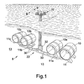
- the power generator 8 also includes a generator assembly 20 ( Figure 1 ) located separately from the turbine housing 12, and a fluid supply means 22 coupling the pump 18 to the generator assembly 20, for supplying fluid from the pump 18 to the generator assembly 20, for generating power.
- FIG. 1 illustrates an embodiment of the present invention including two or more, in particular four underwater turbine units 10, 10a, 10b and 10c.
- Each of the units 10a-10c are similar to the turbine unit 10 and like components share the same reference numerals.
- the fluid supply means 22 couples each turbine unit pump 18 to the generator assembly 20.
- Each of the turbine units 10-10c are mounted by respective mounting frames 11, 11a, 11b and 11c to the seabed 13 and are aligned with the main direction of tidal flow, as indicated by the arrow B-B'.
- the turbine unit housing 12 includes an outer housing sleeve 24 and an inner housing sleeve 26, which defines the fluid flow channel 14.
- the inner housing sleeve 26 is formed in the shape of a divergent-convergent-divergent venturi, which forms a flow restriction in the fluid flow channel 14. This has the effect of increasing the velocity of fluid flow through the flow channel 14 in the direction of the arrow A or A'.
- the housing 12 is substantially symmetrical in a longitudinal direction so that the turbine unit 10 is operative in either of two substantially opposing directions.
- the turbine means 16 comprises a single stage rotor 17 and stator 19 combination, similar to that disclosed in the Applicant's granted UK Patent No. 2 302 348 .
- the rotor 17 carries a number of rotor blades 21 and the stator 19 a number of stator blades 23.
- the stator 19 is shown partially cut-away in Figure 2 , for illustration purposes.
- the pump 18 comprises a pump of the type disclosed in the Applicant's co-pending PCT Patent Publication No. WO 02/36964 , and is coupled directly to the turbine means 16 by a turbine output shaft 28, for rotation with and by the turbine means 16.
- the fluid supply means comprises a fluid conduit 30, which couples the pump 18 to the generator assembly 20.
- liquid flowing through the liquid flow channel 14 drives the turbine means, to rotate the rotor and thus the output shaft 28, driving the pump 18 to pump fluid to the generator assembly 20.
- the driving liquid in this case seawater, which drives the turbine means 16 is also supplied by the pump 18 to the generator assembly 20.
- the generator assembly 20 is mounted on a platform 32 mounted on the seabed 13, and generally comprises a generator turbine means (not shown) such as a pelton wheel and a generator unit (not shown) coupled to the pelton wheel.
- a generator turbine means such as a pelton wheel
- a generator unit (not shown) coupled to the pelton wheel.
- the pelton wheel is thus driven by fluid supplied from the pump 18 to rotate and drive the generator unit, to generate electrical power.
- each of the turbine units 10-10c are connected via respective conduits 30 to the generator assembly 20, such that fluid is supplied to a common generator.
- Mounting of the generator assembly 20 separately from the housing, in particular at the surface on the platform 32, is particularly advantageous as this both assists in maintenance of the generator assembly 20 and reduces construction and maintenance costs. This is in part because the generator assembly is provided above the sea surface, and therefore does not to be sealed against the ingress of seawater.
- the generator assembly 20 is connected via submarine cable to a local onshore power grid, to feed the AC or DC electrical power generated directly into the local grid.
- the generator assembly 20 may include batteries (not shown) for storing the generated electricity.
- turbine units 10, 10a, 10b, 10c typically have a liquid entry angle of ⁇ 25° from the longitudinal axis thereof, and therefore do not need to be aligned with ebb or flow tides.
- FIG. 3 a further feature of the power generator 8 of Fig 1 is illustrated, in accordance with an alternative embodiment of the present invention.
- Each turbine unit 10-10c includes a housing part 34 which is releasably mounted in the turbine housing 12.
- the housing part 34 carries the turbine means 16 and the pump 18, and is removable for maintenance, as illustrated in Figure 3 .
- the outer housing part 24 of the turbine housing 12 includes an opening 36 extending partly around the outer housing sleeve 24.
- a hatch 38 ( Figure 3 ) is opened to allow access to the housing part 34.
- the conduit 30 includes a connection 31, which couples the conduit 30 to a section 33 of conduit coupled to the pump 18. In this fashion, the housing part 34 may be removed for maintenance to the turbine means 16 and/or pump 18, following opening of the hatch 38 and release of the connection 31.
- Figure 3 shows a vessel 40 on site removing the housing part 34 for maintenance, using a crane 42. This is particularly advantageous as this allows maintenance without having to remove the whole turbine unit 10 from the seabed 13.
- the turbine means 16 would be expected to rotate at approximately 60 rpm in a 3 knot current.
- FIG. 4 there is shown a housing 12 of a turbine unit 10 forming part of a power generator 8 in accordance with a further alternative embodiment of the present invention.
- the venturi comprises at least one frusto-conical body 100a,100b,100c a cylindrical body 102 and an at least second frusto-conical body 104a,104b,104c.
- a gap 106 is provided between a divergent end 108 of one first/second frusto-conical body 100,104 and an adjacent convergent end 110 of one further first/second frusto-conical body 100,104, the divergent end 108 of the one first/second frusto-conical body 100,104 being smaller in diameter than the convergent end 110 of the one further first/second frusto-conical body 100,104.
- the frusto-conical body may be straight edged or concaved inwards.
- the divergent end 108 of the one first/second frusto-conical body 100,104 is substantially longitudinally coincident with the convergent end 110 of the one further first/second frusto-conical body 100,104.
- the housing 12 has an overall length of around 20m, the ends 112 of the symmetrical venturi an internal diameter of 15 to 20m and typically around 17.5m, the cylindrical body 102 a length of 2m and an internal diameter of 10m.
- the radial size of the gap 108 is 1m, and the further first/second frusto-conical body 100,104 has a length of 2m.
- FIG. 5 there is shown a housing 12 of a turbine unit 10 forming part of a power generator 8 in accordance with a still further alternative embodiment of the present invention.
- the venturi comprises a pair of frusto-conical bodies 100b and a pair of horn shaped bodies 100a, gaps 106 being provided between each frusto-conical body 100b, and adjacent horn shaped body 100a.
- the fluid supply means may comprise means for combining the fluid from each turbine unit pump separately from or outside the generator assembly, for example, by a manifold, which may be an underwater manifold.
- the turbine housing may comprise a single housing sleeve which may define the flow channel.
- the turbine means may comprise a multiple stage rotor and stator combination, or any other suitable turbine means.
- the turbine means may comprise a number of turbine bodies coupled ogether, each including one or multiple stage rotor and stator combinations.
- the pump may be located separately from the turbine housing.
- the turbine housing may be movably secured to an underwater surface to allow movement to face the direction of main or tidal flow.
- the turbine means may include a rotor only, without a stator.
- the flow channel is advantageously of circular cross-section, other cross-sections are possible, e.g. oval, elliptical, square or rectangular.
Claims (29)
- Unité de turbine sous-marine (10 ; 10a ; 10b ; 10c), comprenant un carter (12) comportant un canal d'écoulement de fluide le traversant, et au moins un moyen de turbine (16) monté dans le canal d'écoulement en vue d'une rotation en réponse à l'écoulement d'un liquide à travers le canal d'écoulement, l'unité de turbine comportant une partie d'unité de turbine (34) pouvant être montée de manière amovible dans l'unité de turbine, la partie de l'unité de turbine comprenant au moins un moyen, le au moins un moyen de turbine ou un moyen de pompe (18), la partie de l'unité de turbine comprenant en outre un élément faisant au moins partie du canal d'écoulement.
- Générateur d'énergie (18), comprenant au moins une unité de turbine sous-marine (10, 10a, 10b, 10c) selon la revendication 1.
- Générateur d'énergie selon la revendication 2, dans lequel le générateur d'énergie comprend un générateur d'énergie électrique.
- Générateur d'énergie selon les revendications 2 ou 3, dans lequel le canal d'écoulement définit un moyen de restriction de l'écoulement.
- Générateur d'énergie selon la revendication 4, dans lequel le moyen de restriction de l'écoulement comprend un venturi.
- Générateur d'énergie selon la revendication 5, dans lequel le venturi comprend un venturi divergent-convergent-divergent, s'effilant à partir d'ouvertures au niveau de chaque extrémité du canal d'écoulement vers une partie interne du canal d'écoulement.
- Générateur d'énergie selon l'une quelconque des revendications 2 à 6, dans lequel le carter est pratiquement symétrique à un emplacement central du au moins un moyen de turbine.
- Générateur d'énergie selon les revendications 6 ou 7, dépendant de la revendication 6, dans lequel le venturi comprend au moins un premier corps en tronc de cône, en tronc de pyramide ou en forme de corne (100a, 100b, 100c), optionnellement un corps cylindrique (102), et au moins un deuxième corps en tronc de cône, en tronc de pyramide ou en forme de corne (104a, 104b, 104c).
- Générateur d'énergie selon la revendication 8, dans lequel un espace (106) est établi entre une extrémité divergente d'un premier/deuxième corps en tronc de cône, en tronc de pyramide ou en forme de corne et une extrémité convergente adjacente d'un premier/deuxième corps additionnel en tronc de cône, en tronc de pyramide ou en forme de corne, l'extrémité divergente dudit premier/deuxième corps en tronc de cône, en tronc de pyramide ou en forme de corne ayant un diamètre inférieur à celui de l'extrémité convergente dudit premier/deuxième corps additionnel en tronc de cône, en tronc de pyramide ou en forme de corne.
- Générateur d'énergie selon la revendication 9, dans lequel l'extrémité divergente dudit premier/deuxième corps en tronc de cône, en tronc de pyramide ou en forme de corne coïncide pratiquement longitudinalement avec l'extrémité convergente dudit premier/deuxième corps additionnel en tronc de cône, en tronc de pyramide ou en forme de corne.
- Générateur d'énergie selon l'une quelconque des revendications 2 à 10, dans lequel le générateur d'énergie comprend en outre :le moyen de pompe, accouplé en service audit au moins un moyen de turbine ;un moyen générateur (20) entraîné par le moyen de turbine et agencé séparément de la au moins une unité de turbine ; etun moyen d'alimentation de fluide, accouplant le moyen de pompe au moyen générateur pour amener le fluide du moyen de pompe vers l'assemblage de générateur, pour produire de l'énergie.
- Générateur d'énergie selon la revendication 11, dans lequel la au moins une/chaque unité de turbine sous-marine est adaptée pour être agencée dans une masse d'eau, le moyen générateur étant adapté pour être agencé hors de la masse d'eau.
- Générateur d'énergie selon les revendications 11 ou 12, dans lequel le liquide est amené en service à partir d'une masse d'eau dans laquelle l'unité de turbine est immergée, le fluide comprenant le liquide.
- Générateur d'énergie selon l'une quelconque des revendications 2 à 13, dans lequel le carter comprend un manchon de carter externe (24) et un manchon de carter interne (26), le manchon interne définissant le canal d'écoulement.
- Générateur d'énergie selon l'une quelconque des revendications 2 à 14, dans lequel le moyen de turbine est sélectionné dans le groupe constitué de :une combinaison de rotor et de stator à un étage (17, 19) ; un seul rotor ; une combinaison de rotor et de stator à plusieurs étages; ou plusieurs corps de turbine accouplés, englobant chacun des combinaisons de rotor et de stator à un étage ou à plusieurs étages.
- Générateur d'énergie selon la revendication 17, dans lequel le moyen de pompe est accouplé audit au moins un moyen de turbine par un arbre de sortie (20) du au moins un moyen de turbine.
- Générateur d'énergie selon l'une quelconque des revendications 2 à 16, dans lequel le moyen de pompe est monté dans le canal d'écoulement et est accouplé directement au moyen de turbine.
- Générateur d'énergie selon l'une quelconque des revendications 11, 16 ou la revendication 17, dépendant de l'une quelconque des revendications 11 à 16, dans lequel le moyen générateur est agencé au niveau de la surface.
- Générateur d'énergie selon l'une quelconque des revendications 11 à 16 ou la revendication 18, dans lequel le moyen générateur comprend un seul moyen de turbine du générateur alimenté par les/chaque unités de turbine, le moyen générateur comprenant le moyen de turbine du générateur et une unité de générateur, le moyen de turbine du générateur entraînant l'unité de générateur.
- Générateur d'énergie selon la revendication 19, dans lequel l'unité de générateur produit de l'énergie électrique sous forme de courant alternatif (AC) ou de courant continu (DC).
- Générateur d'énergie selon les revendications 19 ou 20, dans lequel le moyen de turbine du générateur comprend une roue Pelton accouplée en service au générateur, le moyen de turbine du générateur étant entraîné par le même liquide que le moyen de turbine de l'unité de turbine sous-marine.
- Générateur d'énergie selon l'une quelconque des revendications 19 à 21, dans lequel l'énergie produite par le moyen générateur est stockée par le moyen générateur ou séparément de celui-ci, ou est amenée directement dans un système d'énergie.
- Générateur d'énergie selon la revendication 11 ou selon l'une quelconque des revendications 12 à 22, dépendant de la revendication 11, dans lequel le moyen d'alimentation de fluide comprend un conduit (30) s'étendant entre le moyen de pompe et le moyen générateur, le moyen d'alimentation de liquide étant accouplé de manière amovible au moins au moyen de pompe et/ou au moyen de turbine, pour permettre la séparation et le retrait de l'un des moyens, le moyen de pompe ou le moyen de turbine, ou des deux, en vue d'une récupération au niveau de la surface.
- Générateur d'énergie selon l'une quelconque des revendications 2 à 23, dans lequel le carter de la turbine peut être fixé sur une surface sous-marine par une structure de montage, de sorte à être pratiquement aligné en service avec la direction de la marée.
- Générateur d'énergie selon la revendication 14, dans lequel le manchon externe du carter établit une ouverture (36) pouvant être fermée par une trappe (38), la partie pouvant être retirée en vue d'un entretien à travers l'ouverture.
- Générateur d'énergie selon l'une quelconque des revendications 6, 8, 9 ou 10, dans lequel le au moins un moyen de turbine est agencé au niveau de la partie la plus étroite du venturi.
- Générateur d'énergie selon la revendication 2, comprenant :un moyen générateur agencé séparément du carter de la turbine ; etun moyen d'alimentation de fluide accouplant le moyen de pompe au moyen générateur pour amener le fluide du moyen de pompe vers le moyen générateur, pour produire de l'énergie.
- Partie d'unité de turbine pour un générateur d'énergie selon l'une quelconque des revendications 2 à 26, dans lequel la partie de l'unité de turbine peut être montée de manière amovible dans une unité de turbine du générateur d'énergie et comprend au moins un moyen, le au moins un moyen de turbine ou le moyen de pompe, et comprenant en outre un élément formant au moins une partie du canal d'écoulement.
- Procédé de production d'énergie électrique par l'intermédiaire du générateur d'énergie selon l'une quelconque des revendications 2 à 27.
Priority Applications (1)
| Application Number | Priority Date | Filing Date | Title |
|---|---|---|---|
| EP09002732A EP2063103A3 (fr) | 2001-10-04 | 2002-10-04 | Générateur électrique et unité de turbine |
Applications Claiming Priority (3)
| Application Number | Priority Date | Filing Date | Title |
|---|---|---|---|
| GBGB0123802.1A GB0123802D0 (en) | 2001-10-04 | 2001-10-04 | Power generator and turbine unit |
| GB0123802 | 2001-10-04 | ||
| PCT/GB2002/004513 WO2003029645A1 (fr) | 2001-10-04 | 2002-10-04 | Generateur d'energie et unite turbine |
Related Child Applications (1)
| Application Number | Title | Priority Date | Filing Date |
|---|---|---|---|
| EP09002732A Division EP2063103A3 (fr) | 2001-10-04 | 2002-10-04 | Générateur électrique et unité de turbine |
Publications (2)
| Publication Number | Publication Date |
|---|---|
| EP1436504A1 EP1436504A1 (fr) | 2004-07-14 |
| EP1436504B1 true EP1436504B1 (fr) | 2009-11-25 |
Family
ID=9923203
Family Applications (2)
| Application Number | Title | Priority Date | Filing Date |
|---|---|---|---|
| EP02800194A Expired - Lifetime EP1436504B1 (fr) | 2001-10-04 | 2002-10-04 | Generateur d'energie et unite turbine |
| EP09002732A Withdrawn EP2063103A3 (fr) | 2001-10-04 | 2002-10-04 | Générateur électrique et unité de turbine |
Family Applications After (1)
| Application Number | Title | Priority Date | Filing Date |
|---|---|---|---|
| EP09002732A Withdrawn EP2063103A3 (fr) | 2001-10-04 | 2002-10-04 | Générateur électrique et unité de turbine |
Country Status (12)
| Country | Link |
|---|---|
| US (2) | US7768145B2 (fr) |
| EP (2) | EP1436504B1 (fr) |
| JP (2) | JP2005504227A (fr) |
| CN (3) | CN101666284A (fr) |
| AT (1) | ATE449909T1 (fr) |
| AU (2) | AU2002334099B2 (fr) |
| CA (1) | CA2462847C (fr) |
| DE (1) | DE60234528D1 (fr) |
| GB (3) | GB0123802D0 (fr) |
| NO (1) | NO329957B1 (fr) |
| NZ (1) | NZ532286A (fr) |
| WO (1) | WO2003029645A1 (fr) |
Cited By (5)
| Publication number | Priority date | Publication date | Assignee | Title |
|---|---|---|---|---|
| US8499874B2 (en) | 2009-05-12 | 2013-08-06 | Icr Turbine Engine Corporation | Gas turbine energy storage and conversion system |
| US8669670B2 (en) | 2010-09-03 | 2014-03-11 | Icr Turbine Engine Corporation | Gas turbine engine configurations |
| US8866334B2 (en) | 2010-03-02 | 2014-10-21 | Icr Turbine Engine Corporation | Dispatchable power from a renewable energy facility |
| US8984895B2 (en) | 2010-07-09 | 2015-03-24 | Icr Turbine Engine Corporation | Metallic ceramic spool for a gas turbine engine |
| US9051873B2 (en) | 2011-05-20 | 2015-06-09 | Icr Turbine Engine Corporation | Ceramic-to-metal turbine shaft attachment |
Families Citing this family (95)
| Publication number | Priority date | Publication date | Assignee | Title |
|---|---|---|---|---|
| GB0123802D0 (en) | 2001-10-04 | 2001-11-21 | Rotech Holdings Ltd | Power generator and turbine unit |
| FR2849474B3 (fr) * | 2002-12-27 | 2004-12-03 | Olivier Jean Noel Juin | Installation de transformation de l'energie cinetique d'un fluide en energie electrique |
| US6955049B2 (en) * | 2003-05-29 | 2005-10-18 | Krouse Wayne F | Machine and system for power generation through movement of water |
| GB2408778A (en) * | 2003-12-04 | 2005-06-08 | Calum Mackinnon | Current stream energy device |
| GB2414279A (en) * | 2004-05-17 | 2005-11-23 | Michael John Wilkinson | Extracting kinetic energy from a flowing fluid |
| US7661922B2 (en) * | 2004-07-06 | 2010-02-16 | Sidney Irving Belinsky | Installation for harvesting energy of tides (IHET) in shallow waters |
| GB0510417D0 (en) * | 2005-05-21 | 2005-06-29 | Rotech Holdings Ltd | Improved turbine |
| JP4595715B2 (ja) * | 2005-07-01 | 2010-12-08 | 正治 内田 | 海底設置型海流発電設備 |
| DE102005032381A1 (de) * | 2005-07-08 | 2007-01-11 | Wobben, Aloys, Dipl.-Ing. | Turbine für eine Wasserkraftanlage |
| GB2442929B (en) * | 2005-08-25 | 2011-02-16 | Inst Energy Applic Technologies Co Ltd | Power generator and power generation method |
| EP1816345A1 (fr) * | 2006-02-02 | 2007-08-08 | Saab Ab | Systeme maremoteur |
| US20080247860A1 (en) * | 2007-04-06 | 2008-10-09 | Timothy Cresci | Hydroelectric power plant and method of generating power |
| FR2898941A1 (fr) * | 2006-03-25 | 2007-09-28 | Max Sardou | Energie renouvelable l'hydrolienne flottante |
| CA2544108C (fr) | 2006-04-19 | 2013-06-04 | Metin Ilbay Yaras | Turbine hydraulique a effet vortex |
| NO325916B1 (no) * | 2006-10-30 | 2008-08-18 | Erde As | Sjokraftverk |
| AU2007200888B1 (en) * | 2007-02-28 | 2007-09-20 | Michael Dileo | Electricity generation device |
| GB2447448A (en) * | 2007-03-12 | 2008-09-17 | Raymond Trefor William Lloyd | Hydro-electric and hydro-thermal system |
| GB0704897D0 (en) * | 2007-03-14 | 2007-04-18 | Rotech Holdings Ltd | Power generator and turbine unit |
| FR2913728A1 (fr) * | 2007-03-14 | 2008-09-19 | Paul Guinard | Dispositif et procede pour capter une energie cinetique d'un fluide naturellement en mouvement |
| US20110008164A1 (en) * | 2007-03-23 | 2011-01-13 | Flodesign Wind Turbine Corporation | Wind turbine |
| US20100316493A1 (en) * | 2007-03-23 | 2010-12-16 | Flodesign Wind Turbine Corporation | Turbine with mixers and ejectors |
| US8376686B2 (en) * | 2007-03-23 | 2013-02-19 | Flodesign Wind Turbine Corp. | Water turbines with mixers and ejectors |
| US20110002781A1 (en) * | 2007-03-23 | 2011-01-06 | Flodesign Wind Turbine Corporation | Wind turbine with pressure profile and method of making same |
| US20090230691A1 (en) * | 2007-03-23 | 2009-09-17 | Presz Jr Walter M | Wind turbine with mixers and ejectors |
| US8026625B2 (en) * | 2007-06-20 | 2011-09-27 | California Institute Of Technology | Power generation systems and methods |
| US7928595B1 (en) * | 2007-09-19 | 2011-04-19 | Julio Gonzalez-Carlo | Electric power generation system for harvesting underwater currents |
| US8575775B1 (en) | 2007-09-19 | 2013-11-05 | Julio Gonzalez-Carlo | Electrical power generation system for harvesting underwater currents |
| US20100148515A1 (en) * | 2007-11-02 | 2010-06-17 | Mary Geddry | Direct Current Brushless Machine and Wind Turbine System |
| DE202007017544U1 (de) * | 2007-12-13 | 2009-04-23 | Schiller, Helmut | Unterwasser Turbine |
| WO2009079787A1 (fr) * | 2007-12-20 | 2009-07-02 | Rsw Inc. | Turbine à récupération d'énergie cinétique |
| GB2456786A (en) * | 2008-01-23 | 2009-07-29 | Pilot Drilling Control Ltd | Turbine cowling |
| JP5345327B2 (ja) * | 2008-02-08 | 2013-11-20 | アラテック・エンジェニャリア・コンスルトリア・エ・レプレゼンタソンイス・リミターダ | 電気エネルギ発生装置の改良 |
| US20100283248A1 (en) | 2009-02-20 | 2010-11-11 | Moffat Brian L | Venturi based ocean wave energy conversion system |
| US8925313B2 (en) | 2008-02-22 | 2015-01-06 | Brian Lee Moffat | Wave energy conversion apparatus |
| WO2009141155A2 (fr) * | 2008-05-22 | 2009-11-26 | Hermann Rich Poppe | Dispositif de production d'énergie comprenant des rotors |
| FR2932234B1 (fr) * | 2008-06-06 | 2012-08-03 | Paul Guinard | Dispositif de tuyere destine a etre dispose dans un ecoulement de fluide |
| US8282338B2 (en) * | 2008-06-06 | 2012-10-09 | Mark Kliewer | Underwater generator |
| DE102008037896A1 (de) * | 2008-08-15 | 2010-02-18 | Ksb Aktiengesellschaft | Energierückgewinnungseinrichtung und Verfahren zur Auslegung |
| US20100059999A1 (en) * | 2008-09-09 | 2010-03-11 | Ching-Shih Teng | Sea Floor Pump Tailrace Hydraulic Generation System |
| US8371801B2 (en) * | 2008-11-13 | 2013-02-12 | Hydro Green Energy, Llc | Systems for improved fluid flows through a turbine |
| US20110018272A1 (en) * | 2008-11-18 | 2011-01-27 | Lehoczky Kalman N | Direct driven free flow turbine |
| DE602008002602D1 (de) * | 2008-12-19 | 2010-10-28 | Openhydro Ip Ltd | Verfahren zum Installieren eines hydroelektrischen Turbinengenerators |
| AU2009343135B2 (en) * | 2009-03-27 | 2015-06-18 | Lone Gull Holdings, Ltd. | Wave energy conversion apparatus |
| NZ597280A (en) * | 2009-06-19 | 2015-03-27 | New World Energy Entpr Ltd | A pressure controlled wind turbine enhancement system |
| US20110109089A1 (en) * | 2009-08-19 | 2011-05-12 | Clarence Edward Frye | Free-flow hydro-powered turbine system |
| US20140028028A1 (en) * | 2009-08-19 | 2014-01-30 | Clarence Edward Frye | Free-flow hydro powered turbine system |
| US8740583B2 (en) * | 2009-09-23 | 2014-06-03 | Single Buoy Moorings, Inc. | Ocean energy conversion |
| GB2467200B (en) * | 2009-11-02 | 2010-12-15 | James O'donnell | Submerged impeller driven pump hydroelectric power generation system |
| GB2470447B (en) * | 2009-11-23 | 2011-10-12 | Microgen Technologies Ltd | Submerged impeller driven pump tidal power generation system |
| GB2477533B (en) * | 2010-02-05 | 2012-05-30 | Rolls Royce Plc | A bidirectional water turbine |
| FR2956702B1 (fr) | 2010-02-22 | 2012-04-27 | Paul Guinard | Systeme de conversion de l'energie d'un fluide naturellement en mouvement |
| US20110254270A1 (en) * | 2010-04-14 | 2011-10-20 | Shamil Sami Ayntrazi | Wave gear drive -WGD |
| DE102010018804A1 (de) | 2010-04-29 | 2011-11-03 | Voith Patent Gmbh | Wasserturbine |
| WO2011160210A2 (fr) * | 2010-06-21 | 2011-12-29 | Mavi Innovations Inc. | Ensemble de conduits pour turbines hydrauliques à impulsions radiales |
| AU2011203539A1 (en) * | 2010-07-13 | 2012-02-02 | Kittel Corporation Ptyltd | Extracting energy from flowing fluids |
| CN102434356B (zh) * | 2010-09-29 | 2015-03-25 | 中山市创想模型设计有限公司 | 一种潮流能发电装置 |
| CN102230442B (zh) * | 2010-12-09 | 2013-03-27 | 胡彬 | 无轴海流涡轮发电机 |
| KR101127565B1 (ko) * | 2011-01-28 | 2012-03-23 | (주)레네테크 | 조류 발전 장치 |
| US20140037449A1 (en) * | 2011-03-28 | 2014-02-06 | Norman Perner | Power Plant for Obtaining Energy from a Flow of a Body of Water, and Method for the Operation Thereof |
| TWI482905B (zh) | 2011-03-30 | 2015-05-01 | Ind Tech Res Inst | 水力發電機 |
| CN103321820B (zh) * | 2011-04-18 | 2016-02-10 | 浙江海洋学院 | 多向自适应悬浮型潮流能水轮机 |
| CN102146867A (zh) * | 2011-04-18 | 2011-08-10 | 浙江海洋学院 | 多向自适应悬浮型潮流能水轮机 |
| JP2012241702A (ja) * | 2011-05-16 | 2012-12-10 | Shinichi Fujita | 水中発電装置 |
| US20130028729A1 (en) * | 2011-07-28 | 2013-01-31 | Jones Jack A | Power generation systems and methods |
| GB2493711B (en) * | 2011-08-12 | 2018-04-25 | Openhydro Ip Ltd | Method and system for controlling hydroelectric turbines |
| EP2581599A3 (fr) * | 2011-10-11 | 2013-04-24 | Seoungil Kang | Récupération d'énergie pendant le traitement d'eaux usées |
| CN102400843A (zh) * | 2011-10-26 | 2012-04-04 | 哈尔滨工程大学 | 导流型反击式双转子潮流能水轮机 |
| AT512418A1 (de) * | 2012-02-14 | 2013-08-15 | Schneeweiss Hans | Freistrom-turbinenanlage |
| FR2993324A1 (fr) * | 2012-07-13 | 2014-01-17 | Pierre Bignon | Pompe et dispositifs et installations comprenant une telle pompe |
| US10094288B2 (en) | 2012-07-24 | 2018-10-09 | Icr Turbine Engine Corporation | Ceramic-to-metal turbine volute attachment for a gas turbine engine |
| CN103114960B (zh) * | 2013-02-05 | 2015-08-19 | 厦门大学 | 可用于低速环境的潮流能发电装置 |
| DE202013002095U1 (de) | 2013-03-04 | 2013-03-20 | Hans Schneeweiss | Freistrom-Turbinenanlage |
| US9074577B2 (en) | 2013-03-15 | 2015-07-07 | Dehlsen Associates, Llc | Wave energy converter system |
| GB201318560D0 (en) | 2013-10-21 | 2013-12-04 | Wellstream Int Ltd | Electrical power generation |
| JP5995222B2 (ja) * | 2014-09-09 | 2016-09-21 | 悠一 桐生 | 潮流発電に用いる水力発電ユニット |
| CN105298715A (zh) * | 2015-08-10 | 2016-02-03 | 方祖彭 | 深水能源发电站、动力站、船舶动力装置及其海上浮城 |
| US10197038B2 (en) * | 2015-09-18 | 2019-02-05 | Charles B. Culpepper | Helical longitudinal blade turbine system including a funnel throat valve comprising a plurality of semi-circular valve plates |
| US9759179B2 (en) * | 2015-09-18 | 2017-09-12 | Charles B. Culpepper | Hydroelectric generator system including helical longitudinal blades forming an open bore and aligned with a current direction |
| CN105332849B (zh) * | 2015-11-23 | 2017-12-08 | 广州航海学院 | 一种双通道同向推动涡轮发电装置 |
| ES2573602B1 (es) * | 2016-03-03 | 2016-12-21 | Perga Ingenieros, S.L. | Dispositivo turbogenerador para la producción de energía eléctrica, y procedimientos de funcionamiento e instalación asociados |
| NO20160787A1 (en) * | 2016-05-10 | 2017-06-19 | Norwegian Tidal Solutions | Underwater electrical power plant |
| CN105863945A (zh) * | 2016-06-07 | 2016-08-17 | 上海海洋大学 | 一种仿生鱼形发电装置 |
| TR201608214A2 (tr) * | 2016-06-16 | 2016-07-21 | Ahmet Biyiklioglu | Deniz ve Okyanus Dalgalarından Elektrik Üretmeyi Sağlayan Sistem |
| US20180051667A1 (en) * | 2016-08-17 | 2018-02-22 | Kai-Te YANG | Flowing water hydroelectric generator |
| US9745951B1 (en) | 2016-11-07 | 2017-08-29 | Robert E. Doyle | Self-positioning robotic subsea power generation system |
| US9784244B1 (en) * | 2017-03-29 | 2017-10-10 | Tarek O. Souryal | Energy collection pod |
| CN107941203A (zh) * | 2017-11-29 | 2018-04-20 | 张建洲 | 一种智能化监测系统及方法 |
| US10947953B2 (en) * | 2018-08-20 | 2021-03-16 | Hydrospark, Inc. | Secondary electric power system and method |
| EP3959434A4 (fr) * | 2019-04-22 | 2023-03-29 | Michael Scot Cummings | Générateur d'énergie à écoulement de fluide continu |
| US20210372359A1 (en) * | 2020-03-03 | 2021-12-02 | Robert C. Selby | Systems and apparatuses for hydrokinetic power production |
| BR102020007224B1 (pt) * | 2020-04-10 | 2021-10-26 | Mauricio Otaviano De Queiroz | Unidade coletora de energia de corrente |
| US11560872B2 (en) | 2021-06-18 | 2023-01-24 | Blue Shark Energy LLC | Hydrokinetic telescopic turbine device |
| US20220403814A1 (en) * | 2021-06-22 | 2022-12-22 | Riahmedia Inc. Dba Marine Kinetic Energy | Systems and methods for power distribution and harnessing of marine hydrokinetic energy |
| GB2619352A (en) * | 2022-06-02 | 2023-12-06 | Tidal Renewable Energy Ltd | Marine hydroelectric generating system |
| CN117231408B (zh) * | 2023-11-16 | 2024-01-26 | 安徽丰洲建设科技有限公司 | 一种水利水轮机组发电设备 |
Family Cites Families (47)
| Publication number | Priority date | Publication date | Assignee | Title |
|---|---|---|---|---|
| US1350187A (en) * | 1918-09-02 | 1920-08-17 | John C Streibich | Submersible water-power device |
| GB362223A (en) | 1931-09-01 | 1931-12-03 | Philip Blackman | Improved means for the utilization of tidal energy |
| US2366732A (en) * | 1943-07-30 | 1945-01-09 | Kalix John | Hydroelectric power unit |
| US2634375A (en) * | 1949-11-07 | 1953-04-07 | Guimbal Jean Claude | Combined turbine and generator unit |
| US3986787A (en) * | 1974-05-07 | 1976-10-19 | Mouton Jr William J | River turbine |
| US4383182A (en) * | 1975-06-11 | 1983-05-10 | Bowley Wallace W | Underwater power generator |
| US4163904A (en) * | 1976-03-04 | 1979-08-07 | Lawrence Skendrovic | Understream turbine plant |
| FR2351277A1 (fr) * | 1976-05-11 | 1977-12-09 | Spie Batignolles | Systeme pour transformer l'energie aleatoire d'un fluide naturel |
| US4159188A (en) * | 1977-07-11 | 1979-06-26 | Atencio Francisco J G | Dam with reversible hydroelectric station |
| US4219303A (en) | 1977-10-27 | 1980-08-26 | Mouton William J Jr | Submarine turbine power plant |
| US4320304A (en) * | 1978-01-30 | 1982-03-16 | New Environment Energy Development Aktiebolag (Need) | Apparatus for increasing the flow speed of a medium and for recovering its kinetic energy |
| US4224527A (en) * | 1978-07-06 | 1980-09-23 | Thompson Jack E | Fluid flow intensifier for tide, current or wind generator |
| US4261171A (en) * | 1978-10-20 | 1981-04-14 | Atencio Francisco J G | Functionally transformable dam with tidal power station |
| US4275989A (en) * | 1979-02-08 | 1981-06-30 | Gutierrez Atencio Francisco J | Reversible pump-turbine |
| JPS55139979A (en) * | 1979-04-18 | 1980-11-01 | Fuji Electric Co Ltd | Electricity generating plant of cylindrical water wheel |
| JPS56132376A (en) | 1980-03-21 | 1981-10-16 | Mitsubishi Heavy Ind Ltd | Ship steering simulator |
| US4352989A (en) * | 1980-08-19 | 1982-10-05 | Gutierrez Atencio Francisco J | Hydromotive set |
| JPS58176478A (ja) | 1982-04-08 | 1983-10-15 | Meidensha Electric Mfg Co Ltd | 流体撹拌発熱装置 |
| US4468153A (en) * | 1982-05-12 | 1984-08-28 | Gutierrez Atencio Francisco J | Symmetric tidal station |
| US4511806A (en) * | 1984-05-22 | 1985-04-16 | Air Ltd. | Pressure drop power generation |
| US4722665A (en) * | 1984-11-07 | 1988-02-02 | Tyson Warren N | Turbine |
| JPS61162612A (ja) * | 1985-01-07 | 1986-07-23 | Hitoshi Konno | 海面上昇による都市水没の防止方法とその装置 |
| JPS62169266A (ja) | 1986-01-22 | 1987-07-25 | Fujitsu Ltd | デ−タ送受信端末装置 |
| JPS62169266U (fr) * | 1986-04-16 | 1987-10-27 | ||
| GB2195717A (en) * | 1986-10-02 | 1988-04-13 | Robert Lewis Morgan | Harnessing water power |
| US4804855A (en) * | 1987-02-13 | 1989-02-14 | Obermeyer Henry K | Hydromotive machine apparatus and method of constructing the same |
| JPH0368571A (ja) | 1989-08-09 | 1991-03-25 | Mect Corp | N―置換2、4、6―トリイミノトリアジン誘導体の製造方法 |
| HU208362B (en) * | 1989-11-15 | 1993-09-28 | Tibor Kenderi | Apparatus for utilizing the flowing energy of water motions |
| JP2627099B2 (ja) | 1990-06-15 | 1997-07-02 | 株式会社ユニシアジェックス | 内燃機関の点火時期制御装置 |
| CN2105578U (zh) | 1991-12-18 | 1992-05-27 | 廖国桢 | 水流驱动泵 |
| WO1994016215A1 (fr) * | 1993-01-09 | 1994-07-21 | Toshitaka Yasuda | Procede de production d'energie hydraulique par jet d'eau |
| US5440176A (en) * | 1994-10-18 | 1995-08-08 | Haining Michael L | Ocean current power generator |
| GB9512602D0 (en) | 1995-06-21 | 1995-08-23 | Susman Hector F A | Improvements in or relating to underwater excavation apparatus |
| JPH09195914A (ja) * | 1996-01-24 | 1997-07-29 | Matsushita Electric Ind Co Ltd | 流体駆動装置 |
| JPH10115278A (ja) | 1996-10-09 | 1998-05-06 | Fuji Electric Co Ltd | バルブ形水車発電装置およびバルブ形水車発電装置用の支持装置 |
| SE508861C2 (sv) | 1997-03-18 | 1998-11-09 | Abb Stal Ab | Anordning för en rotormaskinanläggning, rotormaskinanläggning och förfarande för demontering av en sektion hos en rörformad vägg |
| US6283673B1 (en) * | 1997-07-10 | 2001-09-04 | The Earth Science Laboratory Corp. | Method of protecting coastal land from rise of surface of the sea |
| FI104119B1 (fi) | 1998-01-28 | 1999-11-15 | Abb Azipod Oy | Vesiturbiinijärjestely |
| RU2139972C1 (ru) * | 1998-04-07 | 1999-10-20 | Игнатов Геннадий Николаевич | Подводная гидроэлектростанция |
| GB2340892A (en) * | 1998-08-21 | 2000-03-01 | Norman Frank Surplus | Water driven pump |
| JP4458641B2 (ja) * | 1999-08-20 | 2010-04-28 | 株式会社東芝 | 軸流水車発電装置 |
| GB0026818D0 (en) | 2000-11-02 | 2000-12-20 | Rotech Holdings Ltd | Fluid machine |
| SE0100141D0 (sv) | 2001-01-17 | 2001-01-17 | Water Crossing Inc | Energialstringssystem |
| GB0123802D0 (en) | 2001-10-04 | 2001-11-21 | Rotech Holdings Ltd | Power generator and turbine unit |
| US7661922B2 (en) * | 2004-07-06 | 2010-02-16 | Sidney Irving Belinsky | Installation for harvesting energy of tides (IHET) in shallow waters |
| GB0510417D0 (en) * | 2005-05-21 | 2005-06-29 | Rotech Holdings Ltd | Improved turbine |
| NO323150B1 (no) * | 2005-11-08 | 2007-01-08 | Elinova As | Integrert vannturbin og generator uten nav |
-
2001
- 2001-10-04 GB GBGB0123802.1A patent/GB0123802D0/en not_active Ceased
-
2002
- 2002-10-04 GB GB0223062A patent/GB2382627B/en not_active Expired - Fee Related
- 2002-10-04 CA CA2462847A patent/CA2462847C/fr not_active Expired - Fee Related
- 2002-10-04 EP EP02800194A patent/EP1436504B1/fr not_active Expired - Lifetime
- 2002-10-04 CN CN200910168303A patent/CN101666284A/zh active Pending
- 2002-10-04 US US10/491,708 patent/US7768145B2/en not_active Expired - Fee Related
- 2002-10-04 JP JP2003532834A patent/JP2005504227A/ja active Pending
- 2002-10-04 DE DE60234528T patent/DE60234528D1/de not_active Expired - Lifetime
- 2002-10-04 NZ NZ532286A patent/NZ532286A/en not_active IP Right Cessation
- 2002-10-04 AT AT02800194T patent/ATE449909T1/de not_active IP Right Cessation
- 2002-10-04 WO PCT/GB2002/004513 patent/WO2003029645A1/fr active Application Filing
- 2002-10-04 CN CN2010106155493A patent/CN102052230A/zh active Pending
- 2002-10-04 CN CNA028241339A patent/CN1599838A/zh active Pending
- 2002-10-04 GB GB0520396A patent/GB2416809B/en not_active Expired - Fee Related
- 2002-10-04 EP EP09002732A patent/EP2063103A3/fr not_active Withdrawn
- 2002-10-04 AU AU2002334099A patent/AU2002334099B2/en not_active Ceased
-
2004
- 2004-04-05 NO NO20041465A patent/NO329957B1/no not_active IP Right Cessation
-
2008
- 2008-02-11 US US12/029,341 patent/US7944073B2/en not_active Expired - Fee Related
-
2009
- 2009-01-26 JP JP2009014084A patent/JP2009115098A/ja active Pending
- 2009-06-05 AU AU2009202276A patent/AU2009202276B2/en not_active Ceased
Cited By (6)
| Publication number | Priority date | Publication date | Assignee | Title |
|---|---|---|---|---|
| US8499874B2 (en) | 2009-05-12 | 2013-08-06 | Icr Turbine Engine Corporation | Gas turbine energy storage and conversion system |
| US8708083B2 (en) | 2009-05-12 | 2014-04-29 | Icr Turbine Engine Corporation | Gas turbine energy storage and conversion system |
| US8866334B2 (en) | 2010-03-02 | 2014-10-21 | Icr Turbine Engine Corporation | Dispatchable power from a renewable energy facility |
| US8984895B2 (en) | 2010-07-09 | 2015-03-24 | Icr Turbine Engine Corporation | Metallic ceramic spool for a gas turbine engine |
| US8669670B2 (en) | 2010-09-03 | 2014-03-11 | Icr Turbine Engine Corporation | Gas turbine engine configurations |
| US9051873B2 (en) | 2011-05-20 | 2015-06-09 | Icr Turbine Engine Corporation | Ceramic-to-metal turbine shaft attachment |
Also Published As
| Publication number | Publication date |
|---|---|
| ATE449909T1 (de) | 2009-12-15 |
| US7768145B2 (en) | 2010-08-03 |
| EP1436504A1 (fr) | 2004-07-14 |
| WO2003029645A1 (fr) | 2003-04-10 |
| GB2382627A (en) | 2003-06-04 |
| CA2462847C (fr) | 2010-07-06 |
| GB0223062D0 (en) | 2002-11-13 |
| CN1599838A (zh) | 2005-03-23 |
| AU2009202276B2 (en) | 2012-04-26 |
| US20090179425A1 (en) | 2009-07-16 |
| GB0123802D0 (en) | 2001-11-21 |
| DE60234528D1 (de) | 2010-01-07 |
| NO329957B1 (no) | 2011-01-31 |
| EP2063103A2 (fr) | 2009-05-27 |
| NZ532286A (en) | 2006-08-31 |
| EP2063103A3 (fr) | 2011-06-01 |
| GB2416809B (en) | 2006-06-28 |
| NO20041465L (no) | 2004-06-01 |
| US7944073B2 (en) | 2011-05-17 |
| CN101666284A (zh) | 2010-03-10 |
| CN102052230A (zh) | 2011-05-11 |
| GB2382627B (en) | 2005-06-08 |
| GB2416809A (en) | 2006-02-08 |
| JP2005504227A (ja) | 2005-02-10 |
| CA2462847A1 (fr) | 2003-04-10 |
| JP2009115098A (ja) | 2009-05-28 |
| US20050001432A1 (en) | 2005-01-06 |
| AU2002334099B2 (en) | 2009-03-05 |
| GB0520396D0 (en) | 2005-11-16 |
| AU2009202276A1 (en) | 2009-07-02 |
Similar Documents
| Publication | Publication Date | Title |
|---|---|---|
| EP1436504B1 (fr) | Generateur d'energie et unite turbine | |
| AU2002334099A1 (en) | Power generator and turbine unit | |
| GB2408294A (en) | Power generator and turbine unit | |
| JP6962816B2 (ja) | 水力発電/流体動力タービンならびにその製作および使用方法 | |
| JP4024208B2 (ja) | 水中用ダクテッドタービン | |
| US8633609B2 (en) | Sub sea central axis turbine with rearwardly raked blades | |
| US20130069369A1 (en) | Renewable Energy Extraction Device | |
| JP6055652B2 (ja) | 水流発電システム用のサブシステム | |
| AU2004280216A1 (en) | Turbine housing and floatation assembly | |
| CA2694150A1 (fr) | Systeme de chemin helicoidal et procede de production d'energie electrique a partir de debits d'eau grace a l'utilisation de turbines ovales et helicoidales | |
| US20230400006A1 (en) | Wave turbine | |
| KR100858586B1 (ko) | 유수로부터 에너지를 얻기 위한 부유전력발전장치 | |
| GB2337305A (en) | A tidal power generator with a vertical axis transverse flow rotor |
Legal Events
| Date | Code | Title | Description |
|---|---|---|---|
| PUAI | Public reference made under article 153(3) epc to a published international application that has entered the european phase |
Free format text: ORIGINAL CODE: 0009012 |
|
| 17P | Request for examination filed |
Effective date: 20040420 |
|
| AK | Designated contracting states |
Kind code of ref document: A1 Designated state(s): AT BE BG CH CY CZ DE DK EE ES FI FR GB GR IE IT LI LU MC NL PT SE SK TR |
|
| AX | Request for extension of the european patent |
Extension state: AL LT LV MK RO SI |
|
| 17Q | First examination report despatched |
Effective date: 20071121 |
|
| GRAP | Despatch of communication of intention to grant a patent |
Free format text: ORIGINAL CODE: EPIDOSNIGR1 |
|
| GRAS | Grant fee paid |
Free format text: ORIGINAL CODE: EPIDOSNIGR3 |
|
| GRAA | (expected) grant |
Free format text: ORIGINAL CODE: 0009210 |
|
| AK | Designated contracting states |
Kind code of ref document: B1 Designated state(s): AT BE BG CH CY CZ DE DK EE ES FI FR GB GR IE IT LI LU MC NL PT SE SK TR |
|
| REG | Reference to a national code |
Ref country code: GB Ref legal event code: FG4D |
|
| REG | Reference to a national code |
Ref country code: CH Ref legal event code: EP |
|
| REG | Reference to a national code |
Ref country code: IE Ref legal event code: FG4D |
|
| REF | Corresponds to: |
Ref document number: 60234528 Country of ref document: DE Date of ref document: 20100107 Kind code of ref document: P |
|
| REG | Reference to a national code |
Ref country code: NL Ref legal event code: VDEP Effective date: 20091125 |
|
| PG25 | Lapsed in a contracting state [announced via postgrant information from national office to epo] |
Ref country code: FI Free format text: LAPSE BECAUSE OF FAILURE TO SUBMIT A TRANSLATION OF THE DESCRIPTION OR TO PAY THE FEE WITHIN THE PRESCRIBED TIME-LIMIT Effective date: 20091125 Ref country code: PT Free format text: LAPSE BECAUSE OF FAILURE TO SUBMIT A TRANSLATION OF THE DESCRIPTION OR TO PAY THE FEE WITHIN THE PRESCRIBED TIME-LIMIT Effective date: 20100325 Ref country code: SE Free format text: LAPSE BECAUSE OF FAILURE TO SUBMIT A TRANSLATION OF THE DESCRIPTION OR TO PAY THE FEE WITHIN THE PRESCRIBED TIME-LIMIT Effective date: 20091125 |
|
| PG25 | Lapsed in a contracting state [announced via postgrant information from national office to epo] |
Ref country code: CY Free format text: LAPSE BECAUSE OF FAILURE TO SUBMIT A TRANSLATION OF THE DESCRIPTION OR TO PAY THE FEE WITHIN THE PRESCRIBED TIME-LIMIT Effective date: 20091125 |
|
| PG25 | Lapsed in a contracting state [announced via postgrant information from national office to epo] |
Ref country code: BE Free format text: LAPSE BECAUSE OF FAILURE TO SUBMIT A TRANSLATION OF THE DESCRIPTION OR TO PAY THE FEE WITHIN THE PRESCRIBED TIME-LIMIT Effective date: 20091125 Ref country code: AT Free format text: LAPSE BECAUSE OF FAILURE TO SUBMIT A TRANSLATION OF THE DESCRIPTION OR TO PAY THE FEE WITHIN THE PRESCRIBED TIME-LIMIT Effective date: 20091125 |
|
| PG25 | Lapsed in a contracting state [announced via postgrant information from national office to epo] |
Ref country code: EE Free format text: LAPSE BECAUSE OF FAILURE TO SUBMIT A TRANSLATION OF THE DESCRIPTION OR TO PAY THE FEE WITHIN THE PRESCRIBED TIME-LIMIT Effective date: 20091125 Ref country code: DK Free format text: LAPSE BECAUSE OF FAILURE TO SUBMIT A TRANSLATION OF THE DESCRIPTION OR TO PAY THE FEE WITHIN THE PRESCRIBED TIME-LIMIT Effective date: 20091125 Ref country code: BG Free format text: LAPSE BECAUSE OF FAILURE TO SUBMIT A TRANSLATION OF THE DESCRIPTION OR TO PAY THE FEE WITHIN THE PRESCRIBED TIME-LIMIT Effective date: 20100225 Ref country code: NL Free format text: LAPSE BECAUSE OF FAILURE TO SUBMIT A TRANSLATION OF THE DESCRIPTION OR TO PAY THE FEE WITHIN THE PRESCRIBED TIME-LIMIT Effective date: 20091125 Ref country code: ES Free format text: LAPSE BECAUSE OF FAILURE TO SUBMIT A TRANSLATION OF THE DESCRIPTION OR TO PAY THE FEE WITHIN THE PRESCRIBED TIME-LIMIT Effective date: 20100308 |
|
| PG25 | Lapsed in a contracting state [announced via postgrant information from national office to epo] |
Ref country code: CZ Free format text: LAPSE BECAUSE OF FAILURE TO SUBMIT A TRANSLATION OF THE DESCRIPTION OR TO PAY THE FEE WITHIN THE PRESCRIBED TIME-LIMIT Effective date: 20091125 Ref country code: SK Free format text: LAPSE BECAUSE OF FAILURE TO SUBMIT A TRANSLATION OF THE DESCRIPTION OR TO PAY THE FEE WITHIN THE PRESCRIBED TIME-LIMIT Effective date: 20091125 |
|
| PLBE | No opposition filed within time limit |
Free format text: ORIGINAL CODE: 0009261 |
|
| STAA | Information on the status of an ep patent application or granted ep patent |
Free format text: STATUS: NO OPPOSITION FILED WITHIN TIME LIMIT |
|
| PG25 | Lapsed in a contracting state [announced via postgrant information from national office to epo] |
Ref country code: GR Free format text: LAPSE BECAUSE OF FAILURE TO SUBMIT A TRANSLATION OF THE DESCRIPTION OR TO PAY THE FEE WITHIN THE PRESCRIBED TIME-LIMIT Effective date: 20100226 |
|
| 26N | No opposition filed |
Effective date: 20100826 |
|
| PG25 | Lapsed in a contracting state [announced via postgrant information from national office to epo] |
Ref country code: IT Free format text: LAPSE BECAUSE OF FAILURE TO SUBMIT A TRANSLATION OF THE DESCRIPTION OR TO PAY THE FEE WITHIN THE PRESCRIBED TIME-LIMIT Effective date: 20091125 |
|
| PG25 | Lapsed in a contracting state [announced via postgrant information from national office to epo] |
Ref country code: MC Free format text: LAPSE BECAUSE OF NON-PAYMENT OF DUE FEES Effective date: 20101031 |
|
| REG | Reference to a national code |
Ref country code: CH Ref legal event code: PL |
|
| PG25 | Lapsed in a contracting state [announced via postgrant information from national office to epo] |
Ref country code: LI Free format text: LAPSE BECAUSE OF NON-PAYMENT OF DUE FEES Effective date: 20101031 Ref country code: CH Free format text: LAPSE BECAUSE OF NON-PAYMENT OF DUE FEES Effective date: 20101031 |
|
| REG | Reference to a national code |
Ref country code: DE Ref legal event code: R119 Ref document number: 60234528 Country of ref document: DE Effective date: 20110502 |
|
| PG25 | Lapsed in a contracting state [announced via postgrant information from national office to epo] |
Ref country code: LU Free format text: LAPSE BECAUSE OF NON-PAYMENT OF DUE FEES Effective date: 20101004 |
|
| PG25 | Lapsed in a contracting state [announced via postgrant information from national office to epo] |
Ref country code: TR Free format text: LAPSE BECAUSE OF FAILURE TO SUBMIT A TRANSLATION OF THE DESCRIPTION OR TO PAY THE FEE WITHIN THE PRESCRIBED TIME-LIMIT Effective date: 20091125 |
|
| PG25 | Lapsed in a contracting state [announced via postgrant information from national office to epo] |
Ref country code: DE Free format text: LAPSE BECAUSE OF NON-PAYMENT OF DUE FEES Effective date: 20110502 |
|
| REG | Reference to a national code |
Ref country code: FR Ref legal event code: PLFP Year of fee payment: 14 |
|
| PGFP | Annual fee paid to national office [announced via postgrant information from national office to epo] |
Ref country code: GB Payment date: 20150930 Year of fee payment: 14 |
|
| PGFP | Annual fee paid to national office [announced via postgrant information from national office to epo] |
Ref country code: FR Payment date: 20150908 Year of fee payment: 14 |
|
| PGFP | Annual fee paid to national office [announced via postgrant information from national office to epo] |
Ref country code: IE Payment date: 20151012 Year of fee payment: 14 |
|
| GBPC | Gb: european patent ceased through non-payment of renewal fee |
Effective date: 20161004 |
|
| REG | Reference to a national code |
Ref country code: IE Ref legal event code: MM4A |
|
| REG | Reference to a national code |
Ref country code: FR Ref legal event code: ST Effective date: 20170630 |
|
| PG25 | Lapsed in a contracting state [announced via postgrant information from national office to epo] |
Ref country code: GB Free format text: LAPSE BECAUSE OF NON-PAYMENT OF DUE FEES Effective date: 20161004 Ref country code: FR Free format text: LAPSE BECAUSE OF NON-PAYMENT OF DUE FEES Effective date: 20161102 |
|
| PG25 | Lapsed in a contracting state [announced via postgrant information from national office to epo] |
Ref country code: IE Free format text: LAPSE BECAUSE OF NON-PAYMENT OF DUE FEES Effective date: 20161004 |