EP1435502B1 - Laminated heat exchanger - Google Patents
Laminated heat exchanger Download PDFInfo
- Publication number
- EP1435502B1 EP1435502B1 EP03029854A EP03029854A EP1435502B1 EP 1435502 B1 EP1435502 B1 EP 1435502B1 EP 03029854 A EP03029854 A EP 03029854A EP 03029854 A EP03029854 A EP 03029854A EP 1435502 B1 EP1435502 B1 EP 1435502B1
- Authority
- EP
- European Patent Office
- Prior art keywords
- refrigerant
- tubes
- distribution
- distribution channels
- tanks
- Prior art date
- Legal status (The legal status is an assumption and is not a legal conclusion. Google has not performed a legal analysis and makes no representation as to the accuracy of the status listed.)
- Expired - Lifetime
Links
- 239000003507 refrigerant Substances 0.000 claims description 199
- 238000009826 distribution Methods 0.000 claims description 103
- 239000011324 bead Substances 0.000 claims description 37
- 238000000638 solvent extraction Methods 0.000 claims description 9
- 230000008878 coupling Effects 0.000 claims description 4
- 238000010168 coupling process Methods 0.000 claims description 4
- 238000005859 coupling reaction Methods 0.000 claims description 4
- 238000007599 discharging Methods 0.000 claims description 2
- 230000000694 effects Effects 0.000 description 8
- 238000004378 air conditioning Methods 0.000 description 7
- 238000001816 cooling Methods 0.000 description 7
- 230000005484 gravity Effects 0.000 description 4
- 238000013459 approach Methods 0.000 description 3
- 230000000052 comparative effect Effects 0.000 description 3
- 238000001704 evaporation Methods 0.000 description 3
- 238000003466 welding Methods 0.000 description 3
- 238000005219 brazing Methods 0.000 description 2
- 230000007423 decrease Effects 0.000 description 2
- 230000008020 evaporation Effects 0.000 description 2
- 238000009827 uniform distribution Methods 0.000 description 2
- WYTGDNHDOZPMIW-RCBQFDQVSA-N alstonine Natural products C1=CC2=C3C=CC=CC3=NC2=C2N1C[C@H]1[C@H](C)OC=C(C(=O)OC)[C@H]1C2 WYTGDNHDOZPMIW-RCBQFDQVSA-N 0.000 description 1
- 230000015572 biosynthetic process Effects 0.000 description 1
- 238000004891 communication Methods 0.000 description 1
- 238000007791 dehumidification Methods 0.000 description 1
- 238000004049 embossing Methods 0.000 description 1
- 238000002474 experimental method Methods 0.000 description 1
- 238000009434 installation Methods 0.000 description 1
- 230000001788 irregular Effects 0.000 description 1
- 239000000463 material Substances 0.000 description 1
- 239000002184 metal Substances 0.000 description 1
- 238000000034 method Methods 0.000 description 1
- 239000003595 mist Substances 0.000 description 1
- 238000013021 overheating Methods 0.000 description 1
- 238000005192 partition Methods 0.000 description 1
- 230000002093 peripheral effect Effects 0.000 description 1
- 238000012545 processing Methods 0.000 description 1
- 238000011144 upstream manufacturing Methods 0.000 description 1
Images


Classifications
-
- F—MECHANICAL ENGINEERING; LIGHTING; HEATING; WEAPONS; BLASTING
- F28—HEAT EXCHANGE IN GENERAL
- F28D—HEAT-EXCHANGE APPARATUS, NOT PROVIDED FOR IN ANOTHER SUBCLASS, IN WHICH THE HEAT-EXCHANGE MEDIA DO NOT COME INTO DIRECT CONTACT
- F28D1/00—Heat-exchange apparatus having stationary conduit assemblies for one heat-exchange medium only, the media being in contact with different sides of the conduit wall, in which the other heat-exchange medium is a large body of fluid, e.g. domestic or motor car radiators
- F28D1/02—Heat-exchange apparatus having stationary conduit assemblies for one heat-exchange medium only, the media being in contact with different sides of the conduit wall, in which the other heat-exchange medium is a large body of fluid, e.g. domestic or motor car radiators with heat-exchange conduits immersed in the body of fluid
- F28D1/03—Heat-exchange apparatus having stationary conduit assemblies for one heat-exchange medium only, the media being in contact with different sides of the conduit wall, in which the other heat-exchange medium is a large body of fluid, e.g. domestic or motor car radiators with heat-exchange conduits immersed in the body of fluid with plate-like or laminated conduits
- F28D1/0308—Heat-exchange apparatus having stationary conduit assemblies for one heat-exchange medium only, the media being in contact with different sides of the conduit wall, in which the other heat-exchange medium is a large body of fluid, e.g. domestic or motor car radiators with heat-exchange conduits immersed in the body of fluid with plate-like or laminated conduits the conduits being formed by paired plates touching each other
- F28D1/0325—Heat-exchange apparatus having stationary conduit assemblies for one heat-exchange medium only, the media being in contact with different sides of the conduit wall, in which the other heat-exchange medium is a large body of fluid, e.g. domestic or motor car radiators with heat-exchange conduits immersed in the body of fluid with plate-like or laminated conduits the conduits being formed by paired plates touching each other the plates having lateral openings therein for circulation of the heat-exchange medium from one conduit to another
- F28D1/0333—Heat-exchange apparatus having stationary conduit assemblies for one heat-exchange medium only, the media being in contact with different sides of the conduit wall, in which the other heat-exchange medium is a large body of fluid, e.g. domestic or motor car radiators with heat-exchange conduits immersed in the body of fluid with plate-like or laminated conduits the conduits being formed by paired plates touching each other the plates having lateral openings therein for circulation of the heat-exchange medium from one conduit to another the plates having integrated connecting members
- F28D1/0341—Heat-exchange apparatus having stationary conduit assemblies for one heat-exchange medium only, the media being in contact with different sides of the conduit wall, in which the other heat-exchange medium is a large body of fluid, e.g. domestic or motor car radiators with heat-exchange conduits immersed in the body of fluid with plate-like or laminated conduits the conduits being formed by paired plates touching each other the plates having lateral openings therein for circulation of the heat-exchange medium from one conduit to another the plates having integrated connecting members with U-flow or serpentine-flow inside the conduits
-
- F—MECHANICAL ENGINEERING; LIGHTING; HEATING; WEAPONS; BLASTING
- F28—HEAT EXCHANGE IN GENERAL
- F28F—DETAILS OF HEAT-EXCHANGE AND HEAT-TRANSFER APPARATUS, OF GENERAL APPLICATION
- F28F3/00—Plate-like or laminated elements; Assemblies of plate-like or laminated elements
- F28F3/02—Elements or assemblies thereof with means for increasing heat-transfer area, e.g. with fins, with recesses, with corrugations
- F28F3/04—Elements or assemblies thereof with means for increasing heat-transfer area, e.g. with fins, with recesses, with corrugations the means being integral with the element
- F28F3/042—Elements or assemblies thereof with means for increasing heat-transfer area, e.g. with fins, with recesses, with corrugations the means being integral with the element in the form of local deformations of the element
- F28F3/044—Elements or assemblies thereof with means for increasing heat-transfer area, e.g. with fins, with recesses, with corrugations the means being integral with the element in the form of local deformations of the element the deformations being pontual, e.g. dimples
-
- F—MECHANICAL ENGINEERING; LIGHTING; HEATING; WEAPONS; BLASTING
- F28—HEAT EXCHANGE IN GENERAL
- F28D—HEAT-EXCHANGE APPARATUS, NOT PROVIDED FOR IN ANOTHER SUBCLASS, IN WHICH THE HEAT-EXCHANGE MEDIA DO NOT COME INTO DIRECT CONTACT
- F28D21/00—Heat-exchange apparatus not covered by any of the groups F28D1/00 - F28D20/00
- F28D2021/0019—Other heat exchangers for particular applications; Heat exchange systems not otherwise provided for
- F28D2021/008—Other heat exchangers for particular applications; Heat exchange systems not otherwise provided for for vehicles
- F28D2021/0085—Evaporators
Definitions
- the present invention relates to a laminated heat exchanger, more particularly, which is constructed to close some of distribution channels in refrigerant distributing sections of tubes to uniformly distribute refrigerant into the tubes thereby improving flow distribution of refrigerant.
- a heat exchanger comprises internal flow channels so that refrigerant flows through the same while performing heat exchange with external air, and is applied to various air conditioning systems.
- Examples of the heat exchanger may include a fin tube type, a serpentine type, a drawn cup type and a parallel flow type which are used according to various conditions.
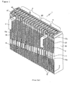
- the evaporator 1 comprises a pair of tanks 40a each having cups 14 with slots 14a formed at upper ends (or lower ends) thereof, a plurality of tubes 10 each having a refrigerant flow section 12 of a generally U-shaped configuration, which is formed by welding two plates 11 with a partitioning bead 13 extended to a predetermined length between a pair of tanks 40a and tanks 40 formed at both sides by the welded tanks 40a, heat radiator fins 50 laminated or stacked between the respective tubes 10 and two end plates 30 installed at outermost sides to reinforce the tubes 10 and the heat radiator fins 50.
- the opposing plates 11 on both sides are coupled to each other with a number of beads, 15 formed by embossing treatment, protruding inward, in order to make refrigerant flowing within the refrigerant flow sections 12 of the tubes 10 become turbulent.
- refrigerant distribution sections 16 are provided at the inlet and outlet sides of the refrigerant flow sections 12 of the tubes 10, having a plurality of distribution channels 16b partitioned by a plurality of beads 16a for refrigerant uniform distribution into the refrigerant flow sections 12.
- the tubes 10 are also provided with inlet side manifolds 17 protruding toward a side of the tanks 40 for communication with the inside and connected with inlet pipes 2 for refrigerant supply, as well as outlet side manifolds 17a connected with outlet pipes 3 for refrigerant discharge.
- the manifolds 17, 17a are formed in the form of a circular pipe by coupling two plates having semicircular manifolds 17, 17a.
- the resulting manifolds 17, 17a are united with the inlet and outlet pipes 2, 3 by means of brazing material of a ring shape and brazed, thereby making it possible to couple the manifolds 17, 17a with the inlet and outlet pipes 2, 3.
- the tanks 40 having inlet side and outlet side manifolds 17, 17a formed for refrigerant, are provided with baffles 60 therein for partitioning between inflow refrigerant and discharged refrigerant.
- the pair of tanks 40 are divided into inlet side 4 for inflow refrigerant and outlet side 5 for discharged refrigerant, from the standpoint of the baffles 60.
- the tank 40 on the inlet side 4 is referred to as A, B and the tank 40 on the outlet side 5 is referred to as C, D in the drawings.
- Refrigerant supplied through the inlet side manifold 17 is then supplied to the A side of the tank 40, flows along the U-shaped refrigerant flow section 12 and finally directed into the B side of the adjacent tank 40 on the other side.
- Refrigerant directed into the B side of the tank 40 flows to the C side of the same tank 40 and flows along the U-shaped refrigerant flow section 12 of the tubes 10.
- refrigerant flows into the D side of the tank 40 it is finally discharged through the outlet side manifold 17a.
- the evaporator 1 In the process of causing inflow and discharge of refrigerant circulating in a cooling system through refrigerant lines, the evaporator 1 conducts evaporation through heat exchange with the air blown between the tubes 10. The endothermic action, due to the latent heat of evaporation of refrigerant, then cools the air blown to the inside of the vehicle room.
- refrigerant flows into the inlet side manifold 17
- refrigerant is supposed to be distributed uniformly to both ends of the tank A side and flow to each of the tubes 10, as shown in FIG. 1 .
- the flow rate of refrigerant flowing directly into the refrigerant flow section 12 of the tube 10a having the manifold 17 formed increases, uniform distribution to both ends of the A side of the tank 40 is not guaranteed. This causes irregular distribution of refrigerant flowing in the tubes 10.
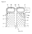
- a top tank-type wherein the tank 40 faces upward
- a bottom tank-type wherein the tank 40 faces downwards
- refrigerant is mainly subject to gravity when it flows in through the manifold 17 and is subject to an inertial force when it makes a U-turn through the refrigerant flow section 12, thereby flowing along the outer shell of the refrigerant flow section 12 of the tube 10a having manifolds formed.
- refrigerant is subject to an inertial force when it flows in through the manifold 17 and is mainly subject to a gravity when it makes a U-turn through the refrigerant flow section 12, thereby flowing near the partitioning bead 13.
- Document JP-A O1/063,788 discloses a stacking-type heat exchanger which, in order to increase the joint strength at the end parts by making joint areas around an inflow tank and an outflow tank larger, at an end plate two deeply recessed parts composing an inflow tank and an outflow tank and a shallow recessed part composing of a heat exchanging chamber are formed in recessed shape by metal processing.
- the plate is equipped with a peripheral edge, a central partition, and a number of ribs at the recessed part in a non-recessed part.
- the document EP-A 0 497 339 relates to an evaporator for use in the refrigerating cycle in an air conditioning system for a vehicle.
- the evaporator is provided with a heat exchanger and an evaporator.
- the heat exchanger has an inlet passageway for leading the refrigerant from the condenser to the evaporator, and an outlet passageway for leading the refrigerant from the evaporator to the compressor.
- the refrigerant distribution section, 16 formed at the inlet and outlet sides of the refrigerant flow section 12 of the tube 10a having the manifold 17, is provided with a plurality of distribution channels 16b partitioned by a plurality of beads 16a, as shown in the drawing.
- the inlet side refrigerant distribution section 16 of the refrigerant flow section 12 adjoining the manifold 17 is formed in such a manner that two outermost distribution channels are interrupted.
- cooling effect is increased by improving the flow distribution of refrigerant, which is a problem of the prior art, to a degree.
- any uneven flow of refrigerant into the refrigerant flow section 12 can be prevented by interrupting the two outermost distribution channels at the inlet side refrigerant distribution section 16 of the refrigerant flow section 12, the approach still has a problem in that the outlet side refrigerant distribution section 16 of the refrigerant flow section 12 has the same structure as in the prior art, that is, has no interrupted distribution channels. As a result, refrigerant still flows uneven and the effect of flow distribution of refrigerant is unreliable.
- refrigerant undergoes heat exchange while passing through the inlet side tubes 4 and then flows toward the outlet side 5.
- refrigerant flows from tank 40 B side of the inlet side 4 to the tank 40 C side of the outlet side 5.
- the refrigerant flowing from the B side of the tank 40 to the C side of the same tank 40 is mainly subject to a gravity. Accordingly, as the refrigerant approaches the end of the C side tank 40, the amount of refrigerant flowing into each of the tubes 10, 10a decreases. This results in the problem that the refrigerant is not distributed uniformly to each of the tubes 10, 10a.
- the present invention has been made to solve the foregoing problems and it is therefore an object of the present invention to provide a laminated heat exchanger in which two outermost distribution channels of refrigerant distribution sections in inlet and outlet sides of refrigerant flow sections are closed in order to uniformly distribute and introduced refrigerant into the tanks as well as prevent any lopsided flow of refrigerant thereby improving refrigerant flow distribution and causing outlet surface temperature and outlet air temperature to be uniform, whereby refrigerant is uniformly distributed and introduced into tubes so as to prevent any problems related with a supercooled or overheated area and icing.
- a laminated heat exchanger comprising:
- FIG. 1 is a perspective view illustrating an evaporator in a conventional heat exchanger
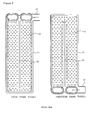
- FIG. 2 is a perspective view illustrating tubes separated from a conventional evaporator
- FIG. 3 is a perspective view illustrating tubes with manifolds separated from a conventional evaporator
- FIG. 4 is a front view illustrating a plate of a tube provided with manifolds in a conventional evaporator
- FIG. 5 illustrates conventional top and bottom mounting type tubes each provided with manifolds in which lopsided refrigerant flow is created
- FIG. 6 illustrates a tube with a manifold in which two outermost distribution channels of an inlet side refrigerant distribution section are closed;
- FIG. 7 is a perspective view illustrating an evaporator of the invention.
- FIG. 8 is a perspective view illustrating separated tubes with manifolds of the invention.
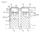
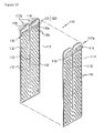
- FIG. 9 illustrates a tube with a manifold of the invention, in which two outermost distribution channels of inlet and outlet side refrigerant distribution sections are closed with closure beads;
- FIG. 10 is a perspective view illustrating separated tubes of the invention.
- FIG. 11 illustrates a tube of the invention, in which two outermost distribution channels of inlet and outlet side refrigerant distribution sections are closed with closure beads;
- FIG. 12 is a graph showing outlet air temperatures with respect to time of the invention, which is compared with that of the prior art.
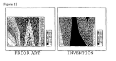
- FIG. 13 illustrates surface temperature distribution in an evaporator of the invention, which is compared with that of the prior art.
- FIG. 7 is a perspective view illustrating an evaporator of the invention
- FIG. 8 is a perspective view illustrating separated tubes with manifolds of the invention
- FIG. 9 illustrates a tube with a manifold of the invention, in which two outermost distribution channels of inlet and outlet side refrigerant distribution sections are closed with closure beads
- FIG. 10 is a perspective view illustrating separated tubes of the invention
- FIG. 11 illustrates a tube of the invention, in which two outermost distribution channels of inlet and outlet side refrigerant distribution sections are closed with closure beads.
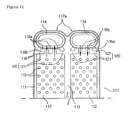
- the evaporator 100 of the invention comprises a pair of tanks 117a having parallel cups 114 formed at the upper end, a plurality of tubes 110 and 110a each having a refrigerant flow section 112 of a generally U-shaped configuration, which is formed by welding a pair plates 111 with the partitioning bead 113 extended to a predetermined length between a pair of tanks 117a and tanks 117 formed at both sides by the welded tanks 117a, heat radiator fins 130 interposed between the tubes 110 and 110a and two end plates 140 disposed at outermost sides of the tubes 110 and 110a to reinforce the tubes 110 and 110a and the heat radiator fins 130.
- baffle 103 for separating inflow refrigerant from outflow refrigerant.
- the baffle 103 divides the tanks 117 and the tubes 110 and 110a into an inlet side 101 into which refrigerant is introduced and an outlet side 102 from which refrigerant is discharged.
- Manifolds 118 and 118a disposed at both sides with respect to the baffle 103 are extended into one of the tanks 117 to communicate with the inside of the tank 117, and coupled with the inlet and outlet pipes 105 and 106 to introduce/discharge refrigerant.
- refrigerant distribution sections 116 having a plurality of distribution channels 116b which are partitioned by at least one bead 116a so that refrigerant can be uniformly distributed and introduced into the refrigerant flow section 112.
- a number of beads 115 are formed in the plates 111 at both sides about the partitioning bead 113 along the refrigerant flow section 112, projected via embossment.
- the beads 115 are regularly arrayed in the shape of gratings along an inclined direction to improve flowing ability of refrigerant and cause turbulent flow to the same.
- coupling faces are provided in flanges formed in outer peripheries of the two plates 111, and the two plates 111 are welded together via brazing by contacting the flanges, the partitioning beads 113 and the beads 115 with each other.
- At least one of the tubes 110 and 110a includes channel-restricting means 120 provided in inlet and outlet side refrigerant distribution sections 116 in a corresponding one of the refrigerant flow sections 112 to restrict two outermost ones of the distribution channels 116b thereof so that refrigerant circulating inside the tanks 117 is uniformly distributed and introduced into the refrigerant flow sections 112 of the tubes 110 and 110a.
- the tubes 110 and 110a of the invention are formed by welding the plates 111 together, in which each of the plates 111 includes a pair of tanks 117a, a refrigerant flow section 112 for connecting the tanks 117a via a partitioning bead 113 formed between the tanks 117a, refrigerant distribution sections 116 provided at inlet and outlet sides of the refrigerant flow section 112 and each having a plurality of distribution channels 116b partitioned by at least one bead 116a, and channel-restricting means 120 provided in each of the refrigerant distribution sections 116 for restricting outermost ones of the distribution channels 116b.
- the channel-restricting means 120 preferably comprise closure beads 121 which are formed in two outermost ones of the distribution channels 116b of the each refrigerant distribution section 116 to close the distribution channels.
- the channel-restricting means 120 may comprise dimple beads formed respectively downstream of two outermost ones of the distribution channels 116b so that the dimple beads can replace the closure beads 121 to restrict the distribution channels 116.
- the dimple beads are so constructed to substantially close the two outermost channels.
- the dimple beads can be modified into various planar shapes such as a circle, quadrangle, triangle and so on.
- Equation 1 the two outermost ones of the distribution channels 116b and the refrigerant flow section 112 are configured according to Equation 1 below:
- P1 and P2 are respectively the widths of the two outermost ones of the distribution channels 116b, and W is the width of the refrigerant flow section 112.
- (P1+P2)/W is preferably determined between 0.25 to 0.32. According to experiment, if (P1+P2)/W is less than 0.25, the channel-restricting means 120 provided in the tubes 110 and 110a produces insignificant effect. If (P1+P2)/W is larger than 0.32, the flow resistance of refrigerant is enlarged.
- the channel-restricting means 120 are equally applied to tubes 110a provided with the manifolds 118 and 118a as well as the common tubes 110 without the manifolds 118 and 118a.
- the channel-restricting means 120 are preferably provided in the tubes 110 placed at the outlet side 102 about the baffle 103. Particularly in those of the tubes 110 placed at the outlet side 102 about the baffle 103, the channel-restricting means 120 are more preferably provided in the tubes 110 placed between the baffle 103 and the tube 110a provided with the outlet side manifold 118a (i.e., a region indicated with a dotted line in FIG. 7 ).
- the plates 111 of the invention are provided upstream of an overheated area to increase the quantity of refrigerant flowing into the overheated area thereby improving entire heat-exchanging ability.
- the position and the number of the plates 111 are determined according to the degree of overheating to realize the effect of the invention.
- the two outermost ones of the distribution channels 116b in each of the refrigerant distribution sections 116 of the tubes 110 are closed by the closure beads 121 or the dimple beads, thereby to reduce the quantity of refrigerant which is directly introduced into the refrigerant flow sections 112 via the distribution channels 116b of the refrigerant distribution sections.
- this structure reduces the quantity of refrigerant directly flowing into the refrigerant flow sections 112 of the tubes 110a with the manifolds 118 so that refrigerant partially flows into the tanks 117.
- the quantity of refrigerant is ensured to the extent that refrigerant can be uniformly distributed to the number of tubes 110 arrayed at both sides of the tubes 110a.
- refrigerant performs heat exchange while flowing through the tubes 110 and 110a in the inlet side 101, and then flows from a "B" section of the tanks 117 to a "C” section of the tanks 117 in order to move toward the outlet side 102.
- the channel-restricting means 120 are provided in the tubes 110 placed between the baffle 103 and the outlet pipe 106 to reduce the quantity of refrigerant directly introduced into the refrigerant flow sections 112 of the respective tubes 110 while refrigerant flows through the tubes 110. Then, because the quantity of refrigerant is ensured to the extent that refrigerant can be uniformly distributed to associated ones of the tubes 110 placed at "C" side ends of the tanks 117, refrigerant can be uniformly distributed through the tubes 110.
- the channel-restricting means 120 can be provided not only in the refrigerant distribution sections 116 of the tubes 110 in the outlet side 101 but also in the refrigerant distribution sections 116 of the tubes 110 in the inlet side 101.
- the two outermost distribution channels of the tube 110a having the inlet side manifold 118 as well as those of some adjacent tubes 110 at both sides of the tube 110a are additionally closed so as to ensure more quantity of refrigerant to the extent that refrigerant fed through the inlet side manifold 118 can be uniformly distributed to the tubes 110 array at both sides. Then, refrigerant can be stably and uniformly distributed and introduced to the tubes 110 at both ends.
- FIG. 12 is a graph showing outlet air temperatures with respect to time to compare outlet air temperatures of an inventive example, in which two outermost distribution channels of inlet and outlet side refrigerant distribution sections are closed according to the invention, with outlet air temperatures of a comparative example, in which two outermost distribution channels of an inlet side refrigerant distribution section are closed according to the prior art.
- the comparative example is raised in temperature according to the passage of time, because refrigerant flow distribution is somewhat ununiform and thus air is discharged without being sufficiently heat exchanged (cooled) owing to icing on the surface of the evaporator 1.
- FIG. 13 illustrates surface temperature distributions of evaporators measured along an arrow I in FIG. 7 , that is, from behind the evaporators, in which plates of the invention and conventional plates are inspected at an air volume of 200CMH in which CMH is m 3 /hour.
- the conventional evaporator shows that supercooled and overheated areas are created owing to ununiform refrigerant quantity flowing through the tubes so that the evaporator surface temperatures have a large temperature difference of about 10.4 °C between maximum and minimum temperatures.
- refrigerant uniformly flows through the tubes to improve the flow distribution of refrigerant.
- the evaporator surface temperatures are distributed relatively uniform, with a temperature difference of about 4.2 °C between maximum and minimum temperatures.
- the distribution channels 116b can be formed in the inlet and outlet sides of the refrigerant flow sections 112 and the refrigerant distribution sections 116 can have the distribution channels 116b formed by the channel-restricting portions(125) in lateral middle portion of the refrigerant flow sections 112 during formation of the plates 111 for constructing the tubes 110 and 10a so that refrigerant flows through the distribution channels 116b in lateral middle portion of the respective refrigerant flow sections 112.
- the invention has been described about the single tank type evaporator having the structure for closing the two outermost distribution channels in the refrigerant distribution sections 116 of the tubes 110 and 110a.
- the invention is not limited to the above structure, but the refrigerant distribution sections 116 for closing the distribution channels 116b can be modified variously within the scope of the invention that will be defined by the appended claims.
- Application of equal structures to a two tank type or four tank type evaporator can expect the same effect as the present invention.
- the two outermost distribution channels of the refrigerant distribution sections in the inlet and outlet sides of the refrigerant flow sections are closed so that refrigerant can be uniformly distributed and introduced into the tanks.
- this can prevent any lopsided flow of refrigerant as well as improve flow distribution of refrigerant so that the outlet surface temperature and outlet air temperature of the heat exchanger can be made uniform.
- refrigerant is uniformly distributed and introduced into the tubes so as to prevent any supercooled or overheated area without icing.
- air of a uniform temperature is introduced into the vehicle room to provide a pleasant environment to the passengers as well as stabilize an air conditioning system and improve cooling efficiency.
- the invention can decrease any probability of icing at the surface of the heat exchanger as well as prevent mist owing to actuation of the air conditioning system even at a low flow rate or air volume.
Landscapes
- Engineering & Computer Science (AREA)
- Physics & Mathematics (AREA)
- Thermal Sciences (AREA)
- Mechanical Engineering (AREA)
- General Engineering & Computer Science (AREA)
- Heat-Exchange Devices With Radiators And Conduit Assemblies (AREA)
- Air-Conditioning For Vehicles (AREA)
- Details Of Heat-Exchange And Heat-Transfer (AREA)
Applications Claiming Priority (4)
| Application Number | Priority Date | Filing Date | Title |
|---|---|---|---|
| KR1020020086956A KR100718262B1 (ko) | 2002-12-30 | 2002-12-30 | 열교환기용 매니폴드 플레이트 |
| KR2002086956 | 2002-12-30 | ||
| KR1020030032832A KR100966746B1 (ko) | 2003-05-23 | 2003-05-23 | 증발기용 플레이트 |
| KR2003032832 | 2003-05-23 |
Publications (3)
| Publication Number | Publication Date |
|---|---|
| EP1435502A2 EP1435502A2 (en) | 2004-07-07 |
| EP1435502A3 EP1435502A3 (en) | 2004-08-25 |
| EP1435502B1 true EP1435502B1 (en) | 2008-02-27 |
Family
ID=32510719
Family Applications (1)
| Application Number | Title | Priority Date | Filing Date |
|---|---|---|---|
| EP03029854A Expired - Lifetime EP1435502B1 (en) | 2002-12-30 | 2003-12-24 | Laminated heat exchanger |
Country Status (5)
| Country | Link |
|---|---|
| US (1) | US6863120B2 (enExample) |
| EP (1) | EP1435502B1 (enExample) |
| JP (1) | JP3992237B2 (enExample) |
| CN (1) | CN1296672C (enExample) |
| DE (1) | DE60319335T2 (enExample) |
Cited By (3)
| Publication number | Priority date | Publication date | Assignee | Title |
|---|---|---|---|---|
| CN106091784A (zh) * | 2015-04-23 | 2016-11-09 | 山东大学 | 一种铜合金材料的换热板片 |
| CN106091785A (zh) * | 2015-04-23 | 2016-11-09 | 山东大学 | 一种板片结构优化的板式换热器 |
| CN106091754A (zh) * | 2015-04-23 | 2016-11-09 | 山东大学 | 一种橡胶材料板式换热器的密封垫片 |
Families Citing this family (22)
| Publication number | Priority date | Publication date | Assignee | Title |
|---|---|---|---|---|
| US20060196645A1 (en) * | 2005-01-07 | 2006-09-07 | Valeo, Inc. | Heat exchanger with multilayer cladded tubes |
| KR20060102376A (ko) * | 2005-03-23 | 2006-09-27 | 한라공조주식회사 | 적층형 열교환기 |
| JP4688538B2 (ja) * | 2005-03-29 | 2011-05-25 | 株式会社日本クライメイトシステムズ | 熱交換器 |
| JP4785397B2 (ja) * | 2005-03-29 | 2011-10-05 | 株式会社日本クライメイトシステムズ | 車両用空調装置の蒸発器 |
| TW200712421A (en) * | 2005-05-18 | 2007-04-01 | Univ Nat Central | Planar heat dissipating device |
| JP4875975B2 (ja) * | 2006-01-31 | 2012-02-15 | 昭和電工株式会社 | 積層型熱交換器 |
| US7413003B2 (en) * | 2006-09-15 | 2008-08-19 | Halla Climate Control Corporation | Plate for heat exchanger |
| AU2008210471B2 (en) | 2007-01-30 | 2013-01-10 | Bradley University | A heat transfer apparatus and method |
| KR101696871B1 (ko) * | 2010-09-06 | 2017-01-16 | 한온시스템 주식회사 | 수랭식 인터쿨러 |
| DE202012102349U1 (de) * | 2011-07-14 | 2012-07-18 | Visteon Global Technologies, Inc. | Batteriekühler |
| CN103375943B (zh) * | 2012-04-27 | 2015-12-09 | 珠海格力电器股份有限公司 | 蒸发器 |
| USD735842S1 (en) * | 2013-02-22 | 2015-08-04 | The Abell Foundation, Inc. | Condenser heat exchanger plate |
| USD736361S1 (en) * | 2013-02-22 | 2015-08-11 | The Abell Foundation, Inc. | Evaporator heat exchanger plate |
| CN105026870B (zh) * | 2013-03-29 | 2017-05-24 | 株式会社日阪制作所 | 板式热交换器 |
| CN105164489B (zh) * | 2013-05-15 | 2018-03-20 | 三菱电机株式会社 | 层叠型集管、热交换器以及空调装置 |
| CN104848516A (zh) * | 2015-06-15 | 2015-08-19 | 广州佳立空调技术有限公司 | 一种空调用层叠式管片及换热器 |
| FR3068773B1 (fr) * | 2017-07-06 | 2019-09-27 | Valeo Systemes Thermiques | Dispositif de regulation thermique de modules de batterie |
| EP3598046B1 (en) * | 2018-07-20 | 2023-05-17 | Valeo Vyminiky Tepla, s.r.o. | Heat exchanger plate and heat exchanger comprising such a heat exchanger plate |
| US11316216B2 (en) | 2018-10-24 | 2022-04-26 | Dana Canada Corporation | Modular heat exchangers for battery thermal modulation |
| KR102230206B1 (ko) * | 2019-07-17 | 2021-03-22 | 한국기계연구원 | 표면 유체막 형성 구조 |
| JP7567021B2 (ja) * | 2020-07-10 | 2024-10-15 | ハンオン システムズ | 熱交換器 |
| CN119562502B (zh) * | 2024-12-20 | 2025-11-25 | 时代天源(深圳)科技有限公司 | 一种双面散热液冷板及电气设备 |
Family Cites Families (12)
| Publication number | Priority date | Publication date | Assignee | Title |
|---|---|---|---|---|
| US4600053A (en) * | 1984-11-23 | 1986-07-15 | Ford Motor Company | Heat exchanger structure |
| JP2536294B2 (ja) * | 1987-09-03 | 1996-09-18 | 日本電装株式会社 | 積層型熱交換器 |
| JPH04177094A (ja) * | 1990-11-13 | 1992-06-24 | Sanden Corp | 積層型熱交換器 |
| US5245843A (en) * | 1991-01-31 | 1993-09-21 | Nippondenso Co., Ltd. | Evaporator |
| AU729629B2 (en) * | 1996-08-12 | 2001-02-08 | Calsonic Corporation | Integral-type heat exchanger |
| US5979544A (en) * | 1996-10-03 | 1999-11-09 | Zexel Corporation | Laminated heat exchanger |
| CN1210583A (zh) * | 1996-12-04 | 1999-03-10 | 株式会社杰克塞尔 | 热交换器 |
| JPH10292995A (ja) * | 1997-02-21 | 1998-11-04 | Zexel Corp | 積層型熱交換器 |
| US6082449A (en) * | 1998-01-27 | 2000-07-04 | Calsonic Corporation | Oil cooler structure |
| US5855240A (en) * | 1998-06-03 | 1999-01-05 | Ford Motor Company | Automotive heat exchanger |
| BE1012044A6 (fr) | 1998-06-18 | 2000-04-04 | Solvay | Procede et installation pour la fabrication d'une solution aqueuse de peroxyde d'hydrogene et solution aqueuse de peroxyde d'hydrogene. |
| JP3911574B2 (ja) * | 2000-01-08 | 2007-05-09 | 漢拏空調株式会社 | 熱交換性能を向上させた積層型熱交換器用プレート及びこれを用いる熱交換器 |
-
2003
- 2003-12-24 DE DE60319335T patent/DE60319335T2/de not_active Expired - Lifetime
- 2003-12-24 EP EP03029854A patent/EP1435502B1/en not_active Expired - Lifetime
- 2003-12-26 JP JP2003435926A patent/JP3992237B2/ja not_active Expired - Fee Related
- 2003-12-29 US US10/747,839 patent/US6863120B2/en not_active Expired - Lifetime
- 2003-12-30 CN CNB2003101102790A patent/CN1296672C/zh not_active Expired - Fee Related
Cited By (6)
| Publication number | Priority date | Publication date | Assignee | Title |
|---|---|---|---|---|
| CN106091784A (zh) * | 2015-04-23 | 2016-11-09 | 山东大学 | 一种铜合金材料的换热板片 |
| CN106091785A (zh) * | 2015-04-23 | 2016-11-09 | 山东大学 | 一种板片结构优化的板式换热器 |
| CN106091754A (zh) * | 2015-04-23 | 2016-11-09 | 山东大学 | 一种橡胶材料板式换热器的密封垫片 |
| CN106091754B (zh) * | 2015-04-23 | 2018-05-15 | 山东大学 | 一种橡胶材料板式换热器的密封垫片 |
| CN106091785B (zh) * | 2015-04-23 | 2018-05-15 | 山东大学 | 一种板片结构优化的板式换热器 |
| CN106091784B (zh) * | 2015-04-23 | 2018-05-15 | 山东大学 | 一种铜合金材料的换热板片 |
Also Published As
| Publication number | Publication date |
|---|---|
| US20040144524A1 (en) | 2004-07-29 |
| EP1435502A2 (en) | 2004-07-07 |
| JP2004212041A (ja) | 2004-07-29 |
| EP1435502A3 (en) | 2004-08-25 |
| CN1296672C (zh) | 2007-01-24 |
| US6863120B2 (en) | 2005-03-08 |
| DE60319335D1 (de) | 2008-04-10 |
| CN1519532A (zh) | 2004-08-11 |
| DE60319335T2 (de) | 2009-02-19 |
| JP3992237B2 (ja) | 2007-10-17 |
Similar Documents
| Publication | Publication Date | Title |
|---|---|---|
| EP1435502B1 (en) | Laminated heat exchanger | |
| US5101890A (en) | Heat exchanger | |
| US6536517B2 (en) | Evaporator | |
| JP3340785B2 (ja) | 冷凍システム又はヒートポンプシステムに使用するための蒸発器又は蒸発器兼凝縮器及びその製造方法並びに蒸発器の少なくとも一部分として用いるための熱交換器 | |
| US8276401B2 (en) | Evaporator | |
| EP2998676B1 (en) | Heat exchanger, in particular a condenser | |
| JP4211998B2 (ja) | 熱交換器用プレート | |
| US20100083694A1 (en) | Evaporator | |
| US20030188857A1 (en) | Heat exchanger for exchanging heat between internal fluid and external fluid and manufacturing method thereof | |
| EP1114974B1 (en) | Plate for stack type heat exchangers and heat exchanger using such plates | |
| US6431264B2 (en) | Heat exchanger with fluid-phase change | |
| JP2004212041A5 (enExample) | ||
| KR100268098B1 (ko) | 열교환기 | |
| JP4686062B2 (ja) | エバポレータ | |
| JP3965901B2 (ja) | 蒸発器 | |
| EP1686339B1 (en) | Heat exchanger | |
| JPH0355490A (ja) | 熱交換器 | |
| EP1703245B1 (en) | Heat exchanger | |
| KR20060009653A (ko) | 열교환기 | |
| JP4547205B2 (ja) | 蒸発器 | |
| KR20020045042A (ko) | 열교환기 튜브 | |
| KR101082474B1 (ko) | 열교환기 | |
| KR100718262B1 (ko) | 열교환기용 매니폴드 플레이트 | |
| KR100966746B1 (ko) | 증발기용 플레이트 | |
| KR101082469B1 (ko) | 열교환기 |
Legal Events
| Date | Code | Title | Description |
|---|---|---|---|
| PUAI | Public reference made under article 153(3) epc to a published international application that has entered the european phase |
Free format text: ORIGINAL CODE: 0009012 |
|
| AK | Designated contracting states |
Kind code of ref document: A2 Designated state(s): AT BE BG CH CY CZ DE DK EE ES FI FR GB GR HU IE IT LI LU MC NL PT RO SE SI SK TR |
|
| AX | Request for extension of the european patent |
Extension state: AL LT LV MK |
|
| PUAL | Search report despatched |
Free format text: ORIGINAL CODE: 0009013 |
|
| AK | Designated contracting states |
Kind code of ref document: A3 Designated state(s): AT BE BG CH CY CZ DE DK EE ES FI FR GB GR HU IE IT LI LU MC NL PT RO SE SI SK TR |
|
| AX | Request for extension of the european patent |
Extension state: AL LT LV MK |
|
| 17P | Request for examination filed |
Effective date: 20050225 |
|
| AKX | Designation fees paid |
Designated state(s): DE FR GB IT PT SE |
|
| RBV | Designated contracting states (corrected) |
Designated state(s): DE FR GB IT PT SE |
|
| GRAP | Despatch of communication of intention to grant a patent |
Free format text: ORIGINAL CODE: EPIDOSNIGR1 |
|
| GRAS | Grant fee paid |
Free format text: ORIGINAL CODE: EPIDOSNIGR3 |
|
| GRAA | (expected) grant |
Free format text: ORIGINAL CODE: 0009210 |
|
| AK | Designated contracting states |
Kind code of ref document: B1 Designated state(s): DE FR GB IT PT SE |
|
| RAP1 | Party data changed (applicant data changed or rights of an application transferred) |
Owner name: HALLA CLIMATE CONTROL CORPORATION |
|
| REG | Reference to a national code |
Ref country code: GB Ref legal event code: FG4D |
|
| REF | Corresponds to: |
Ref document number: 60319335 Country of ref document: DE Date of ref document: 20080410 Kind code of ref document: P |
|
| PG25 | Lapsed in a contracting state [announced via postgrant information from national office to epo] |
Ref country code: SE Free format text: LAPSE BECAUSE OF FAILURE TO SUBMIT A TRANSLATION OF THE DESCRIPTION OR TO PAY THE FEE WITHIN THE PRESCRIBED TIME-LIMIT Effective date: 20080527 Ref country code: PT Free format text: LAPSE BECAUSE OF FAILURE TO SUBMIT A TRANSLATION OF THE DESCRIPTION OR TO PAY THE FEE WITHIN THE PRESCRIBED TIME-LIMIT Effective date: 20080721 |
|
| ET | Fr: translation filed | ||
| PLBE | No opposition filed within time limit |
Free format text: ORIGINAL CODE: 0009261 |
|
| STAA | Information on the status of an ep patent application or granted ep patent |
Free format text: STATUS: NO OPPOSITION FILED WITHIN TIME LIMIT |
|
| 26N | No opposition filed |
Effective date: 20081128 |
|
| PG25 | Lapsed in a contracting state [announced via postgrant information from national office to epo] |
Ref country code: IT Free format text: LAPSE BECAUSE OF FAILURE TO SUBMIT A TRANSLATION OF THE DESCRIPTION OR TO PAY THE FEE WITHIN THE PRESCRIBED TIME-LIMIT Effective date: 20080227 |
|
| REG | Reference to a national code |
Ref country code: DE Ref legal event code: R082 Ref document number: 60319335 Country of ref document: DE Representative=s name: KOEPE & PARTNER, DE |
|
| REG | Reference to a national code |
Ref country code: FR Ref legal event code: CD Owner name: HALLA VISTEON CLIMATE CONTROL CORPORATION Effective date: 20130827 |
|
| REG | Reference to a national code |
Ref country code: DE Ref legal event code: R082 Ref document number: 60319335 Country of ref document: DE Representative=s name: SCHWABE SANDMAIR MARX PATENTANWAELTE RECHTSANW, DE Effective date: 20130910 Ref country code: DE Ref legal event code: R081 Ref document number: 60319335 Country of ref document: DE Owner name: HANON SYSTEMS, KR Free format text: FORMER OWNER: HALLA CLIMATE CONTROL CORP., DAEJEON, KR Effective date: 20130910 Ref country code: DE Ref legal event code: R081 Ref document number: 60319335 Country of ref document: DE Owner name: HALLA VISTEON CLIMATE CONTROL CORP., KR Free format text: FORMER OWNER: HALLA CLIMATE CONTROL CORP., DAEJEON, KR Effective date: 20130910 Ref country code: DE Ref legal event code: R082 Ref document number: 60319335 Country of ref document: DE Representative=s name: KOEPE & PARTNER, DE Effective date: 20130910 |
|
| REG | Reference to a national code |
Ref country code: FR Ref legal event code: PLFP Year of fee payment: 13 |
|
| REG | Reference to a national code |
Ref country code: DE Ref legal event code: R082 Ref document number: 60319335 Country of ref document: DE Representative=s name: SCHWABE SANDMAIR MARX PATENTANWAELTE RECHTSANW, DE Ref country code: DE Ref legal event code: R082 Ref document number: 60319335 Country of ref document: DE Representative=s name: SSM SANDMAIR PATENTANWAELTE RECHTSANWALT PARTN, DE |
|
| REG | Reference to a national code |
Ref country code: DE Ref legal event code: R082 Ref document number: 60319335 Country of ref document: DE Representative=s name: SCHWABE SANDMAIR MARX PATENTANWAELTE RECHTSANW, DE Ref country code: DE Ref legal event code: R081 Ref document number: 60319335 Country of ref document: DE Owner name: HANON SYSTEMS, KR Free format text: FORMER OWNER: HALLA VISTEON CLIMATE CONTROL CORP., DAEJEON, KR Ref country code: DE Ref legal event code: R082 Ref document number: 60319335 Country of ref document: DE Representative=s name: SSM SANDMAIR PATENTANWAELTE RECHTSANWALT PARTN, DE |
|
| REG | Reference to a national code |
Ref country code: FR Ref legal event code: PLFP Year of fee payment: 14 |
|
| REG | Reference to a national code |
Ref country code: FR Ref legal event code: CD Owner name: HANON SYSTEMS, KP Effective date: 20161213 |
|
| REG | Reference to a national code |
Ref country code: FR Ref legal event code: PLFP Year of fee payment: 15 |
|
| PGFP | Annual fee paid to national office [announced via postgrant information from national office to epo] |
Ref country code: DE Payment date: 20211109 Year of fee payment: 19 Ref country code: FR Payment date: 20211115 Year of fee payment: 19 Ref country code: GB Payment date: 20211111 Year of fee payment: 19 |
|
| REG | Reference to a national code |
Ref country code: DE Ref legal event code: R119 Ref document number: 60319335 Country of ref document: DE |
|
| GBPC | Gb: european patent ceased through non-payment of renewal fee |
Effective date: 20221224 |
|
| PG25 | Lapsed in a contracting state [announced via postgrant information from national office to epo] |
Ref country code: GB Free format text: LAPSE BECAUSE OF NON-PAYMENT OF DUE FEES Effective date: 20221224 Ref country code: DE Free format text: LAPSE BECAUSE OF NON-PAYMENT OF DUE FEES Effective date: 20230701 |
|
| PG25 | Lapsed in a contracting state [announced via postgrant information from national office to epo] |
Ref country code: FR Free format text: LAPSE BECAUSE OF NON-PAYMENT OF DUE FEES Effective date: 20221231 |