EP1434079B1 - Autostereoskopisches anzeigesystem - Google Patents
Autostereoskopisches anzeigesystem Download PDFInfo
- Publication number
- EP1434079B1 EP1434079B1 EP02745434A EP02745434A EP1434079B1 EP 1434079 B1 EP1434079 B1 EP 1434079B1 EP 02745434 A EP02745434 A EP 02745434A EP 02745434 A EP02745434 A EP 02745434A EP 1434079 B1 EP1434079 B1 EP 1434079B1
- Authority
- EP
- European Patent Office
- Prior art keywords
- prism
- halves
- vision system
- autostereoscopic vision
- autostereoscopic
- Prior art date
- Legal status (The legal status is an assumption and is not a legal conclusion. Google has not performed a legal analysis and makes no representation as to the accuracy of the status listed.)
- Expired - Lifetime
Links
Images


Classifications
-
- H—ELECTRICITY
- H04—ELECTRIC COMMUNICATION TECHNIQUE
- H04N—PICTORIAL COMMUNICATION, e.g. TELEVISION
- H04N13/00—Stereoscopic video systems; Multi-view video systems; Details thereof
- H04N13/30—Image reproducers
- H04N13/302—Image reproducers for viewing without the aid of special glasses, i.e. using autostereoscopic displays
- H04N13/32—Image reproducers for viewing without the aid of special glasses, i.e. using autostereoscopic displays using arrays of controllable light sources; using moving apertures or moving light sources
-
- G—PHYSICS
- G02—OPTICS
- G02B—OPTICAL ELEMENTS, SYSTEMS OR APPARATUS
- G02B30/00—Optical systems or apparatus for producing three-dimensional [3D] effects, e.g. stereoscopic images
- G02B30/20—Optical systems or apparatus for producing three-dimensional [3D] effects, e.g. stereoscopic images by providing first and second parallax images to an observer's left and right eyes
- G02B30/26—Optical systems or apparatus for producing three-dimensional [3D] effects, e.g. stereoscopic images by providing first and second parallax images to an observer's left and right eyes of the autostereoscopic type
-
- G—PHYSICS
- G02—OPTICS
- G02B—OPTICAL ELEMENTS, SYSTEMS OR APPARATUS
- G02B30/00—Optical systems or apparatus for producing three-dimensional [3D] effects, e.g. stereoscopic images
- G02B30/20—Optical systems or apparatus for producing three-dimensional [3D] effects, e.g. stereoscopic images by providing first and second parallax images to an observer's left and right eyes
- G02B30/34—Stereoscopes providing a stereoscopic pair of separated images corresponding to parallactically displaced views of the same object, e.g. 3D slide viewers
- G02B30/35—Stereoscopes providing a stereoscopic pair of separated images corresponding to parallactically displaced views of the same object, e.g. 3D slide viewers using reflective optical elements in the optical path between the images and the observer
-
- H—ELECTRICITY
- H04—ELECTRIC COMMUNICATION TECHNIQUE
- H04N—PICTORIAL COMMUNICATION, e.g. TELEVISION
- H04N13/00—Stereoscopic video systems; Multi-view video systems; Details thereof
- H04N13/30—Image reproducers
- H04N13/346—Image reproducers using prisms or semi-transparent mirrors
-
- H—ELECTRICITY
- H04—ELECTRIC COMMUNICATION TECHNIQUE
- H04N—PICTORIAL COMMUNICATION, e.g. TELEVISION
- H04N13/00—Stereoscopic video systems; Multi-view video systems; Details thereof
- H04N13/30—Image reproducers
- H04N13/366—Image reproducers using viewer tracking
-
- H—ELECTRICITY
- H04—ELECTRIC COMMUNICATION TECHNIQUE
- H04N—PICTORIAL COMMUNICATION, e.g. TELEVISION
- H04N13/00—Stereoscopic video systems; Multi-view video systems; Details thereof
- H04N13/30—Image reproducers
- H04N13/398—Synchronisation thereof; Control thereof
Definitions
- the invention comprises an autostereoscopic vision system for visualising photographs/images of stereoscopic pairs permitting the reproduction of the three-dimensional vision effect of stereoscopic pairs on the basis of a transparent prism of optimised dimensions and low cost.
- the invention comes within those devices that use lenses and/or mirrors which permit visualisation of each of the photographs solely by one of the eyes in order to produce the three-dimensional vision effect.
- the invention consists of a autostereoscopic vision system comprising the characteristics recited in claim 1, such that when positioning the user's eyes in front of the upper face of the prismatic body with the proper angle and at a distance which can be greater than 2 meters, each eye visualises the corresponding stereogram via that upper face of the prismatic body, reproducing the three-dimensional vision effect of the photographs/images.
- the first prism is a central prism with triangular base having at least two sides of equal length, in such a manner that on the faces making up those sides the second transparent prism and a third transparent prism are arranged, both presenting an identical configuration in which their bases are constituted by a right-angle triangle.
- This structure is arranged in such a way that the edge joining the two sides of equal length of the central prismatic body points towards the upper face of the rectangular prismatic body, so that the upper face is constituted by one of the faces of the second prism and by another of the faces of the third prism, both arranged in a single plane.
- the photographs/images are divided into two halves; so, the left photograph/image consists of a left half A and a right half B, and the right photograph/image consists of a left half C and a right half D, in such a way that these halves are arranged in the following order: C, A, D, B; the halves A and B being inverted, in other words, as if the image on them were being visualised from the opposite face.
- half A is arranged in a lower left half of a lower face of the first prism;
- half D is arranged next to half A in a lower right half of the lower face of the first prism;
- half C is arranged in a plane perpendicular to the half A, but inverted for which it is located in the lower part of the lateral face of the second prism;
- half B is arranged in a plane perpendicular to half D, though inverted for which it is located in the lower part of a side face of the third prism.
- the halves C, A, D, B are arranged on a foldable surface in such a way that the halves constituting the central prism are folded and separated in order to locate the halves A and D on the inner faces of the halves constituting the central prism, with the halves C and D being located on the lower face of the rectangular prismatic body which is formed by one of the faces of each of the second and third prisms, in other words, the half C is arranged on the lower face of the second prism and the half D is arranged on the lower face of the third prism.
- the projection of halves C, D is done by means of a plurality of optical fibres, while in another embodiment of the invention these halves are projected by means of concave mirrors.
- the halves A and D present a reduced size compared to halves C and D in order to compensate for the effect of the concave mirrors and permit correct visualisation in three dimensions.
- the central prism constituting it is materialised from two symmetric prismatic halves, in which case the upper face of the said rectangular prismatic body is constituted by the two halves of the central prism.
- the first prism is a central prism with triangular base, which includes at least two sides of equal length, with the particular feature that arranged on the faces including these sides are the second prism and the third prism, both being of identical configuration of rhomboid bases, in which case the halves C and B are located on one of the faces of the second and third prism, and the halves A and D are located on one of the faces of the central prism; and all this in such a manner that all the halves are arranged in a single plane.
- plane mirrors consists of an embodiment in which one of the faces of the central prism constitutes the upper face of the set of prisms, with a mirror being arranged laterally and as a continuation of the lateral face of the second and third prism, beneath which mirror are located the halves C and B respectively, while the halves A and D are located on one of the faces of the central prism.
- Another characteristic common to all the embodiments described consists of the fact that in the upper face of the prismatic body provision has been made for some lenses for adjusting the join of the halves of the stereoscopic photographs/images, increasing the image in three dimensions, eliminating the visualisation of the edges of the prisms and adjusting the point of visualisation.
- the invention optionally includes means of detection of a displaced position of the user with respect to the upper face of the rectangular prismatic body and means of displacement of some optical means in order to position the user's eyes in front of the upper face of the rectangular prismatic body.
- the means of detection of a displaced position of the user are defined by at least one sensor which, starting from a control circuit, governs the functioning of a servomotor for displacing the optical means.
- the sensor can, for example, be an infrared or ultrasound sensor.
- the optical means are defined by a lens or a variable prism of the type used in video cameras.
- the optical means can be defined by the actual rectangular prismatic body, in such a way that the servomotor governs the displacement of that body in order to position the user's eyes in front of the upper face of it.
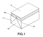
- a lens 8 is provided on the upper face of the second prism 2, which constitutes the upper face of the prismatic body, in such a way that it enlarges the three-dimensional image at the same time as eliminating the vision of the inner edges of the prismatic body, in addition to permitting the observation position of the user to be varied. This position varies depending on the material used in the manufacture of the transparent prisms.
- a directional filter 9 which helps to centre the position of the observer on the upper face of the prismatic body, for which said filter darkens the lateral vision, in such a way that it helps the observer to have an immediate visualisation of the three-dimensional effect, so that even for persons who are unfamiliar with the functioning of the system it helps them to position themselves in front of the upper face of the prismatic body in order to perceive the three-dimensional effect.
- the viewfinder exclusively shows the image in three-dimensional format since, outside the front angle, the image becomes dark and is therefore not visible.
- Figure 1 shows an embodiment in which the first prism is constituted by a central prism 10 of triangular base, with two equal sides, on which is arranged the second prism 11 and a third prism 12.
- two lenses 8a are used instead of one in order to achieve the reproduction of the three-dimensional effect, as is described below.
- the illumination device has not been represented for the sake of simplicity.
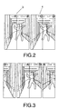
- the photographs 3 and 4 need to be divided into two equal halves. So, the left photograph 3 has been divided into the left half A and the right half B, while the right photograph 4 has been divided into the left half C and the right half D.
- halves are arranged in the following order: C, A, D and B, with the particular feature that the halves C and B are inverted, in other words rotated through 180° with respect to their longitudinal axis (figure 3).
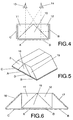
- the inverted halves C and B have been arranged on the side walls of the second prism 11 and of the third prism 12, as shown in figure 4, in such a way that the left eye 13 visualises the half A and the half B but inverted due to the effect of the prism, due to which this half must originally be positioned inverted.
- the right eye 14 visualises the halves D and C, reproducing the three-dimensional vision effect, which is improved by means of including the two lenses 8a, each of which favours the joining of the corresponding halves to be visualised with each eye.
- Figure 4 and beyond do not include the illumination element, lenses, nor the directional filter, in order to simplify those figures, but such elements are arranged in all of the embodiments of the invention since they improve the three-dimensional effect, as has been commented on earlier.
- Figure 5 shows an embodiment in which the second prism 2 and the third prism 3 have a rhomboid base.
- the halves A and D are arranged on the lower face of the first prism 10 and the halves C and B are respectively arranged on the lower face of the second and third prism, without being inverted, on account of the effect of the new arrangement of the second and third prism.
- Figure 6 shows another embodiment that uses the structure of figure 4 and in which the halves C, A, D and B are arranged in a form identical to the embodiment of figure 5, for which mirrors 16, 17 are also added which cause the projection of the halves C and D onto the side walls of the second prism 11 and of the third prism 12.
- Figure 7 shows a similar embodiment to that of figure 6, but in this case the projection of the halves C and B on the side faces of the second prism 11 and of the third prism 12, respectively, is effected by means of optical fibres 18.
- Figure 8 represents another embodiment equivalent to that of figure 7, but in this case the projection of the halves C and B on the side walls of the second prism 11 and of the third prism 12 respectively is effected by means of concave mirrors 19.
- the format of the halves of the stereoscopic pair to use is the format represented in figure 9, in which the halves A and D have smaller proportions than halves C and B in order to compensate the effect produced by the concave mirrors, since they reduce the image.
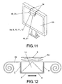
- Figure 10 shows another embodiment in which the central prism 10 is divided into two symmetric halves 10a and 10b and the rectangular prismatic unit is inverted, in other words in this case the upper face of the rectangular prismatic body is constituted by one of the faces of each of the symmetric halves 10a and 10b.
- This embodiment has the aim of permitting visualisation of photographs printed on a foldable surface 25, such as for example the surface of a magazine, in such a way that separation of the halves 10a and 10b is permitted in order to arrange the halves A and D in the inner faces of the halves constituting the central prism, at the same time as arranging the halves C and B on the lower face of the second and third prism 11 and 12 respectively, in such a way that the three-dimensional vision effect is reproduced on the basis of photographs printed in magazines, newspapers, etc., according to the described format.
- the prisms are provided with securing means 24 on the screen 23, in such a way that visualisation in three dimensions is facilitated.
- the securing means 24 are supporting the prisms shown in the embodiment of figure 8.
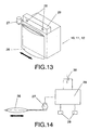
- Figure 13 shows an embodiment which includes a lens 26 that is connected to a servomotor 27 which is governed by a control circuit 29 fed by the corresponding battery 30, and which is also connected to two infrared sensors 28.
- the lens 26 is located in front of the upper face of the prism, which in the example of embodiment has been arranged laterally so that the user can visualise the three-dimensional effect from a lateral position, in such a way that if the user is not in front of that upper face but is instead to one side of it, this is detected by the infrared sensors 28, in such a way that the control circuit 29 governs the functioning of the servomotor 27 in order to locate the lens 26 so that the user's eyes remain in front of that upper face of the prism, thus obtaining the three-dimensional vision effect.
- the sensors can be of any other type, such as ultrasound for example, and the lens can consist of another kind of optical device, as might be a variable prism of the kind used in video cameras.
- the servomotor to govern the position of the prism with respect to the location of the user's eyes.
Landscapes
- Engineering & Computer Science (AREA)
- Multimedia (AREA)
- Signal Processing (AREA)
- Physics & Mathematics (AREA)
- General Physics & Mathematics (AREA)
- Optics & Photonics (AREA)
- Stereoscopic And Panoramic Photography (AREA)
- Holo Graphy (AREA)
- Testing, Inspecting, Measuring Of Stereoscopic Televisions And Televisions (AREA)
Claims (23)
- Autostereoskopisches Betrachtungssystem zum Visualisieren von Stereogrammen (3, 4), das umfasst:dadurch gekennzeichnet, dass:ein Stereogramm (3, 4);wenigstens ein erstes mittleres transparentes Prisma (10, 10a, 10b) mit einer dreieckigen Basis;ein zweites transparentes Prisma (2, 11);wobei das zweite transparente Prisma und das dritte transparente Prisma einen äquivalenten Aufbau haben;das System des Weiteren ein drittes transparentes Prisma (12, 15) umfasst;das zweite transparente Prisma (2, 11) und das dritte transparente Prisma (12, 15) jeweils an einer entsprechenden ersten Fläche des wenigstens einen ersten Prismas (10, 10a, 10b) angeordnet sind;
und das Stereogramm (3, 4) umfasst:ein linkes Foto/Bild (3), das in zwei Hälften, d.h. eine linke Hälfte (A) und eine rechte Hälfte (B), unterteilt ist;ein rechtes Foto/Bild (4), das in zwei Hälften, d.h. eine linke Hälfte (C) und eine rechte Hälfte (D), unterteilt ist;die linke Hälfte (A) des linken Fotos/Bildes (3) und die rechte Hälfte (B) des rechten Fotos/Bildes (4) auf einer zweiten Fläche des wenigstens einen ersten Prismas (10, 10a, 10b) angeordnet sind;das wenigstens eine erste Prisma (10, 10a, 10b), das zweite Prisma (2, 11) und das dritte Prisma (12, 15) einen prismatischen Körper bilden, so dass, wenn die Augen eines Benutzers (13, 14) vor einer oberen Fläche des prismatischen Körpers in einem geeigneten Winkel positioniert werden, die Augen (13, 14) über die obere Fläche des prismatischen Körpers ein entsprechendes Stereogramm (3, 4) visualisieren und ein dreidimensionaler Seheffekt der Fotos/Bilder wiedergegeben wird. - Autostereoskopisches Betrachtungssystem nach Anspruch 1, wobei das erste Prisma (10, 10a, 10b), das zweite Prisma (2, 11) und das dritte Prisma (12,15) einen rechteckigen prismatischen Körper bilden, in dem das erste Prisma (10, 10a, 10b) wenigstens zwei Seitenflächen gleicher Länge umfasst, das zweite Prisma (2, 11) und das dritte Prisma (12, 15) an den Flächen angeordnet sind und das zweite Prisma (2, 11) sowie das dritte Prisma (12, 15) Basen in Form rechtwinkliger Dreiecke haben.
- Autostereoskopisches Betrachtungssystem nach Anspruch 2, wobei eine Kante, die die zwei Seitenflächen des ersten Prismas (10) verbindet, zur oberen Fläche des rechteckigen prismatischen Körpers zeigt und die obere Fläche eine der Flächen des zweiten Prismas (2, 11) und eine andere der Flächen des dritten Prismas (12, 15) umfasst und die zwei Flächen in einer Ebene angeordnet sind.
- Autostereoskopisches Betrachtungssystem nach Anspruch 3, wobei Hälften A, B, C, D in der Reihenfolge C, A, D, B angeordnet sind und die Hälften C und B umgekehrt sind.
- Autostereoskopisches Betrachtungssystem nach Anspruch 4, wobei:Hälfte A in einer unteren linken Hälfte einer unteren Fläche des ersten Prismas (10) angeordnet ist;Hälfte D neben Hälfte A in einer unteren rechten Hälfte der unteren Fläche des ersten Prismas (10) angeordnet ist;Hälfte C in einer Ebene senkrecht zu Hälfte A angeordnet ist und sich im unteren Teil einer Seitenfläche des zweiten Prismas (2, 11) befindet;Hälfte B in einer Ebene senkrecht zu Hälfte D angeordnet ist und sich im unteren Teil einer Seitenfläche des dritten Prismas (12, 15) befindet.
- Autostereoskopisches Betrachtungssystem nach Anspruch 3, wobei Hälften C, A, D, B in einer einzelnen Ebene angeordnet sind.
- Autostereoskopisches Betrachtungssystem nach Anspruch 6, wobei Hälften C und B auf die Seitenflächen des zweiten Prismas (2, 11) und des dritten Prismas (12, 15) projiziert sind.
- Autostereoskopisches Betrachtungssystem nach Anspruch 7, wobei Hälften C und B mittels einer Vielzahl von Lichtleitfasern (18) projiziert werden.
- Autostereoskopisches Betrachtungssystem nach Anspruch 7, wobei Hälften C und B mit konkaven Spiegeln (19) projiziert werden und eine Linse (21) an den Hälften C und B angeordnet ist und das Bild auf die konkaven Spiegel (19) richtet, die ihrerseits das Bild auf einen Diffusions-Glasschirm (20) projizieren, der sich an den Seitenflächen des zweiten Prismas (2, 11) und des dritten Prismas (12, 15) befindet.
- Autostereoskopisches Betrachtungssystem nach Anspruch 9, wobei Hälften A und D, verglichen mit Hälften C und B, geringere Größe haben, um einen Effekt auszugleichen, der durch die konkaven Spiegel erzeugt wird, und richtige Visualisierung in drei Dimensionen zu ermöglichen.
- Autostereoskopisches Betrachtungssystem nach Anspruch 7, wobei die Bilder mit Planspiegeln (17) projiziert werden.
- Autostereoskopisches Betrachtungssystem nach Anspruch 2, wobei das erste Prisma (10) zwei symmetrische Prismenhälften (10a, 10b) umfasst und die obere Fläche des rechteckigen Prismenkörpers Flächen der zwei Prismenhälften (10a, 10b) umfasst.
- Autostereoskopisches Betrachtungssystem nach Anspruch 4 und 12, wobei die Foto-Hälften C, A, D, B auf einer klappbaren Oberfläche (25) angeordnet sind, so dass die Foto-Hälften geklappt werden und die Hälften (10a, 10b), die das erste Prisma (10) bilden, getrennt werden, um die Hälften A und D an inneren Flächen der Hälften (10a, 10b) anzuordnen, die das erste Prisma bilden, und die Hälften C und B an der inneren Fläche des rechteckigen Prismenkörpers anzuordnen, so dass die Hälfte C an der unteren Fläche des zweiten Prismas (2, 11) angeordnet ist und die Hälfte B an der unteren Fläche des dritten Prismas (12, 15) angeordnet ist.
- Autostereoskopisches Betrachtungssystem nach Anspruch 2 und 6, wobei das erste Prisma ein mittleres Prisma (10) mit dreieckiger Basis ist, das zwei Seiten gleicher Länge umfasst, das zweite Prisma (2, 11) und das dritte Prisma (12, 15) an den Flächen angeordnet sind, die die gleichlangen Seiten umfassen, und beide Prismen gleichen Aufbau mit Rhomboidbasen haben, so dass die Hälfte C an der unteren Fläche des zweiten Prismas (2, 11) angeordnet ist, die Hälfte B an der unteren Fläche des dritten Prismas (12, 15) angeordnet ist und sich die Hälften A und D an der unteren Fläche des mittleren Prismas (10) befinden.
- Autostereoskopisches Betrachtungssystem nach einem der vorangehenden Ansprüche, wobei die Hälften C, A, D, B auf einem Band (22) angeordnet sind, das durch eine Steuerschaltung gesteuert von einem Motor gezogen wird, um eine Vielzahl stereoskopischer Fotos mittels Steuerung des Motors durch Einwirken auf eine Vielzahl von Antriebssteuerungen zu visualisieren.
- Autostereoskopisches Betrachtungssystem nach einem der Ansprüche 3 und 6, wobei die Hälften C, A, D, B auf einem Video-, Computer- oder Fernsehbildschirm (23) visualisiert werden.
- Autostereoskopisches Betrachtungssystem nach Anspruch 16, wobei das System eine Sicherungseinrichtung (24) umfasst, die die Gruppe von Prismen auf dem Bildschirm (23) zum Erzeugen des dreidimensionalen Seheffektes der Hälften C, A, D, B sichert.
- Autostereoskopisches Betrachtungssystem nach einem der vorangehenden Ansprüche, wobei das System eine Beleuchtungseinrichtung (5) zum Beleuchten der Hälften C, A, D, B umfasst.
- Autostereoskopisches Betrachtungssystem nach Anspruch 18, wobei die Beleuchtungseinrichtung eine weiße Leuchtdiode (5) umfasst.
- Autostereoskopisches Betrachtungssystem nach einem der vorangehenden Ansprüche, wobei die obere Fläche des Prismenkörpers mit Linsen (8a) zum Einstellen der Verbindung der Hälften C, A, D, B versehen ist, um das Bild in drei Dimensionen zu vergrößern und die Visualisierung der Kanten der Prismen aufzuheben und den Punkt der Visualisierung einzustellen.
- Autostereoskopisches Betrachtungssystem nach einem der vorangehenden Ansprüche, wobei das System ein Richtungsfilter (9) umfasst, das seitliches Sehen einschränkt, um zu bewirken, dass sich ein Betrachter vor der oberen Fläche positioniert.
- Autostereoskopisches Betrachtungssystem nach einem der vorangehenden Ansprüche, wobei das System eine Erfassungseinrichtung, die eine verschobene Position des Benutzers in Bezug auf die obere Fläche des rechteckigen Prismenkörpers erfasst, sowie eine Verschiebeeinrichtung umfasst, die eine Vielzahl optischer Einrichtungen verschiebt, um die Augen eines Benutzers vor der oberen Fläche des rechteckigen Prismenkörpers zu positionieren.
- Autostereoskopisches Betrachtungssystem nach Anspruch 22, wobei die Erfassungseinrichtung, die eine verschobene Position des Benutzers erfasst, wenigstens einen Sensor (28) umfasst, der über eine Steuerschaltung die Funktion eines Servomotors (27) zum Verschieben der optischen Einrichtungen steuert.
Applications Claiming Priority (3)
| Application Number | Priority Date | Filing Date | Title |
|---|---|---|---|
| ES200101523 | 2001-06-29 | ||
| ES200101523A ES2180445B1 (es) | 2001-06-29 | 2001-06-29 | Sistema de vision autoestereoscopica. |
| PCT/ES2002/000318 WO2003003100A1 (es) | 2001-06-29 | 2002-06-28 | Sistema de vision autoestereoscopica |
Publications (2)
| Publication Number | Publication Date |
|---|---|
| EP1434079A1 EP1434079A1 (de) | 2004-06-30 |
| EP1434079B1 true EP1434079B1 (de) | 2005-01-26 |
Family
ID=8498245
Family Applications (1)
| Application Number | Title | Priority Date | Filing Date |
|---|---|---|---|
| EP02745434A Expired - Lifetime EP1434079B1 (de) | 2001-06-29 | 2002-06-28 | Autostereoskopisches anzeigesystem |
Country Status (7)
| Country | Link |
|---|---|
| US (1) | US7113334B2 (de) |
| EP (1) | EP1434079B1 (de) |
| JP (1) | JP4138648B2 (de) |
| AT (1) | ATE288089T1 (de) |
| DE (1) | DE60202786T2 (de) |
| ES (1) | ES2180445B1 (de) |
| WO (1) | WO2003003100A1 (de) |
Families Citing this family (12)
| Publication number | Priority date | Publication date | Assignee | Title |
|---|---|---|---|---|
| GB2406731A (en) * | 2003-08-30 | 2005-04-06 | Sharp Kk | Multiple view display having directional backlight |
| KR101109584B1 (ko) * | 2004-11-27 | 2012-01-31 | 삼성전자주식회사 | 조명유니트 및 이를 채용한 화상투사장치 |
| US20060152580A1 (en) * | 2005-01-07 | 2006-07-13 | Synthosys, Llc | Auto-stereoscopic volumetric imaging system and method |
| TWI265315B (en) * | 2005-12-16 | 2006-11-01 | Ind Tech Res Inst | Autostereoscopic display apparatus |
| US20190025603A1 (en) * | 2017-07-21 | 2019-01-24 | John Stephen HUDGINS | Optical device for creating three-dimensional effect from a two-dimensional display screen |
| US10298921B1 (en) * | 2018-02-27 | 2019-05-21 | Looking Glass Factory, Inc. | Superstereoscopic display with enhanced off-angle separation |
| US10558038B2 (en) * | 2018-03-16 | 2020-02-11 | Sharp Kabushiki Kaisha | Interpupillary distance adjustment mechanism for a compact head-mounted display system |
| US10527863B2 (en) * | 2018-03-16 | 2020-01-07 | Sharp Kabushiki Kaisha | Compact head-mounted display system |
| US11449004B2 (en) | 2020-05-21 | 2022-09-20 | Looking Glass Factory, Inc. | System and method for holographic image display |
| US11415728B2 (en) | 2020-05-27 | 2022-08-16 | Looking Glass Factory, Inc. | System and method for holographic displays |
| WO2021262860A1 (en) | 2020-06-23 | 2021-12-30 | Looking Glass Factory, Inc. | System and method for holographic communication |
| WO2022119940A1 (en) | 2020-12-01 | 2022-06-09 | Looking Glass Factory, Inc. | System and method for processing three dimensional images |
Family Cites Families (8)
| Publication number | Priority date | Publication date | Assignee | Title |
|---|---|---|---|---|
| US710237A (en) * | 1902-06-16 | 1902-09-30 | Thomas Knight Barnard | Photochromoscopic apparatus. |
| FR2509481A1 (fr) * | 1981-07-08 | 1983-01-14 | Materiel Micrographie | Visionneuse stereoscopique |
| EP0095492A1 (de) * | 1981-12-07 | 1983-12-07 | RACKHAM, Anthony Charles | Stereoskopische bilder |
| GB2199154B (en) * | 1985-02-05 | 1989-03-15 | Pilkington Perkin Elmer Ltd | Improvements in or relating to optical apparatus |
| US5245472A (en) * | 1991-06-26 | 1993-09-14 | Hughes Aircraft Company | High-efficiency, low-glare X-prism |
| US5528426A (en) * | 1994-07-14 | 1996-06-18 | Tti Medical | Laser block beam splitter for microscopes |
| US5986801A (en) * | 1996-11-08 | 1999-11-16 | Volk; Donald A. | Image reinverter for stereo microscope |
| ES1036488Y (es) * | 1997-02-19 | 1998-01-01 | Romeo Granados Juan Sebastian | Dispositivo para obtener reproducciones estereoscopicas sobre plano. |
-
2001
- 2001-06-29 ES ES200101523A patent/ES2180445B1/es not_active Expired - Fee Related
-
2002
- 2002-06-28 AT AT02745434T patent/ATE288089T1/de not_active IP Right Cessation
- 2002-06-28 DE DE60202786T patent/DE60202786T2/de not_active Expired - Fee Related
- 2002-06-28 JP JP2003509223A patent/JP4138648B2/ja not_active Expired - Fee Related
- 2002-06-28 EP EP02745434A patent/EP1434079B1/de not_active Expired - Lifetime
- 2002-06-28 WO PCT/ES2002/000318 patent/WO2003003100A1/es active IP Right Grant
-
2003
- 2003-12-23 US US10/745,292 patent/US7113334B2/en not_active Expired - Fee Related
Also Published As
| Publication number | Publication date |
|---|---|
| JP4138648B2 (ja) | 2008-08-27 |
| WO2003003100A1 (es) | 2003-01-09 |
| JP2004533650A (ja) | 2004-11-04 |
| US20040165262A1 (en) | 2004-08-26 |
| DE60202786T2 (de) | 2006-01-05 |
| ES2180445B1 (es) | 2004-04-01 |
| ES2180445A1 (es) | 2003-02-01 |
| EP1434079A1 (de) | 2004-06-30 |
| ATE288089T1 (de) | 2005-02-15 |
| DE60202786D1 (de) | 2005-03-03 |
| US7113334B2 (en) | 2006-09-26 |
Similar Documents
| Publication | Publication Date | Title |
|---|---|---|
| NL1029968C2 (nl) | Digitale stereocamera/digitale stereo videocamera, 3-dimensionele display, 3-dimensionele projector, en printer en stereoviewer. | |
| JP4376194B2 (ja) | ディジタルステレオカメラ又はディジタルステレオビデオカメラ並びに3dディスプレイ又は3dプロジェクタ並びにプリンタ | |
| CN101097296B (zh) | 投影仪的光学系统和相应的投影仪 | |
| EP1434079B1 (de) | Autostereoskopisches anzeigesystem | |
| CA2473375A1 (en) | Apparatus for stereoscopic photography | |
| US5225861A (en) | Apparatus for projection of three-dimensional images | |
| JPH07504766A (ja) | 2組のスクリーンによる画像形成システム | |
| JP2004533650A5 (de) | ||
| EP1039327A2 (de) | Videoskop und seine Anzeigeeinheit | |
| JP2002125245A (ja) | 立体画像編集方法、立体画像編集装置および立体画像表示システム | |
| US5586818A (en) | Three dimensional projection system | |
| EP0680621B1 (de) | Stereoskopisches betrachtungsgeraet | |
| JPH09327042A (ja) | 3次元立体映像信号変換装置の撮影用のビデオカメラ装置及び該装置に用いられる光学アダプター装置 | |
| CN2240156Y (zh) | 立体照像机 | |
| JP4646437B2 (ja) | 立体画像観察装置 | |
| JP2005222026A (ja) | 立体視装置 | |
| JP2000131644A (ja) | 立体写真観察装置 | |
| JP2500420B2 (ja) | 投射型立体表示装置 | |
| JPH07134345A (ja) | 立体画像撮影装置、立体画像撮影用アタッチメントおよび立体画像観賞装置 | |
| JPH0728178A (ja) | 投写型3次元画像表示装置 | |
| JP2615363B2 (ja) | 立体画像装置 | |
| JP2001305478A (ja) | 立体画像投影装置およびアダプタ | |
| JP2002341474A (ja) | 立体画像撮影用アダプタ及び立体画像撮影装置 | |
| JPS6348093A (ja) | ステレオテレビ方式及びその装置 | |
| JP4300886B2 (ja) | 立体視用ビュアー |
Legal Events
| Date | Code | Title | Description |
|---|---|---|---|
| PUAI | Public reference made under article 153(3) epc to a published international application that has entered the european phase |
Free format text: ORIGINAL CODE: 0009012 |
|
| 17P | Request for examination filed |
Effective date: 20040123 |
|
| AK | Designated contracting states |
Kind code of ref document: A1 Designated state(s): AT BE CH CY DE DK ES FI FR GB GR IE IT LI LU MC NL PT SE TR |
|
| GRAP | Despatch of communication of intention to grant a patent |
Free format text: ORIGINAL CODE: EPIDOSNIGR1 |
|
| GRAS | Grant fee paid |
Free format text: ORIGINAL CODE: EPIDOSNIGR3 |
|
| GRAA | (expected) grant |
Free format text: ORIGINAL CODE: 0009210 |
|
| AK | Designated contracting states |
Kind code of ref document: B1 Designated state(s): AT BE CH CY DE DK ES FI FR GB GR IE IT LI LU MC NL PT SE TR |
|
| PG25 | Lapsed in a contracting state [announced via postgrant information from national office to epo] |
Ref country code: IT Free format text: LAPSE BECAUSE OF FAILURE TO SUBMIT A TRANSLATION OF THE DESCRIPTION OR TO PAY THE FEE WITHIN THE PRESCRIBED TIME-LIMIT;WARNING: LAPSES OF ITALIAN PATENTS WITH EFFECTIVE DATE BEFORE 2007 MAY HAVE OCCURRED AT ANY TIME BEFORE 2007. THE CORRECT EFFECTIVE DATE MAY BE DIFFERENT FROM THE ONE RECORDED. Effective date: 20050126 Ref country code: AT Free format text: LAPSE BECAUSE OF FAILURE TO SUBMIT A TRANSLATION OF THE DESCRIPTION OR TO PAY THE FEE WITHIN THE PRESCRIBED TIME-LIMIT Effective date: 20050126 Ref country code: BE Free format text: LAPSE BECAUSE OF FAILURE TO SUBMIT A TRANSLATION OF THE DESCRIPTION OR TO PAY THE FEE WITHIN THE PRESCRIBED TIME-LIMIT Effective date: 20050126 Ref country code: NL Free format text: LAPSE BECAUSE OF FAILURE TO SUBMIT A TRANSLATION OF THE DESCRIPTION OR TO PAY THE FEE WITHIN THE PRESCRIBED TIME-LIMIT Effective date: 20050126 Ref country code: TR Free format text: LAPSE BECAUSE OF FAILURE TO SUBMIT A TRANSLATION OF THE DESCRIPTION OR TO PAY THE FEE WITHIN THE PRESCRIBED TIME-LIMIT Effective date: 20050126 Ref country code: FI Free format text: LAPSE BECAUSE OF FAILURE TO SUBMIT A TRANSLATION OF THE DESCRIPTION OR TO PAY THE FEE WITHIN THE PRESCRIBED TIME-LIMIT Effective date: 20050126 |
|
| RAP1 | Party data changed (applicant data changed or rights of an application transferred) |
Owner name: ALEJO TREVIJANO, JOSE JAVIER |
|
| REG | Reference to a national code |
Ref country code: GB Ref legal event code: FG4D |
|
| RIN1 | Information on inventor provided before grant (corrected) |
Inventor name: ALEJO TREVIJANO, JOSE JAVIER |
|
| REG | Reference to a national code |
Ref country code: CH Ref legal event code: EP |
|
| REG | Reference to a national code |
Ref country code: IE Ref legal event code: FG4D |
|
| REF | Corresponds to: |
Ref document number: 60202786 Country of ref document: DE Date of ref document: 20050303 Kind code of ref document: P |
|
| PG25 | Lapsed in a contracting state [announced via postgrant information from national office to epo] |
Ref country code: GR Free format text: LAPSE BECAUSE OF FAILURE TO SUBMIT A TRANSLATION OF THE DESCRIPTION OR TO PAY THE FEE WITHIN THE PRESCRIBED TIME-LIMIT Effective date: 20050426 Ref country code: SE Free format text: LAPSE BECAUSE OF FAILURE TO SUBMIT A TRANSLATION OF THE DESCRIPTION OR TO PAY THE FEE WITHIN THE PRESCRIBED TIME-LIMIT Effective date: 20050426 Ref country code: DK Free format text: LAPSE BECAUSE OF FAILURE TO SUBMIT A TRANSLATION OF THE DESCRIPTION OR TO PAY THE FEE WITHIN THE PRESCRIBED TIME-LIMIT Effective date: 20050426 |
|
| PG25 | Lapsed in a contracting state [announced via postgrant information from national office to epo] |
Ref country code: ES Free format text: LAPSE BECAUSE OF FAILURE TO SUBMIT A TRANSLATION OF THE DESCRIPTION OR TO PAY THE FEE WITHIN THE PRESCRIBED TIME-LIMIT Effective date: 20050507 |
|
| REG | Reference to a national code |
Ref country code: CH Ref legal event code: NV Representative=s name: ISLER & PEDRAZZINI AG |
|
| PG25 | Lapsed in a contracting state [announced via postgrant information from national office to epo] |
Ref country code: CY Free format text: LAPSE BECAUSE OF FAILURE TO SUBMIT A TRANSLATION OF THE DESCRIPTION OR TO PAY THE FEE WITHIN THE PRESCRIBED TIME-LIMIT Effective date: 20050628 |
|
| NLV1 | Nl: lapsed or annulled due to failure to fulfill the requirements of art. 29p and 29m of the patents act | ||
| PLBE | No opposition filed within time limit |
Free format text: ORIGINAL CODE: 0009261 |
|
| STAA | Information on the status of an ep patent application or granted ep patent |
Free format text: STATUS: NO OPPOSITION FILED WITHIN TIME LIMIT |
|
| 26N | No opposition filed |
Effective date: 20051027 |
|
| ET | Fr: translation filed | ||
| REG | Reference to a national code |
Ref country code: CH Ref legal event code: PCAR Free format text: ISLER & PEDRAZZINI AG;POSTFACH 1772;8027 ZUERICH (CH) |
|
| PG25 | Lapsed in a contracting state [announced via postgrant information from national office to epo] |
Ref country code: PT Free format text: LAPSE BECAUSE OF NON-PAYMENT OF DUE FEES Effective date: 20050626 |
|
| PGFP | Annual fee paid to national office [announced via postgrant information from national office to epo] |
Ref country code: IE Payment date: 20090629 Year of fee payment: 8 Ref country code: MC Payment date: 20090630 Year of fee payment: 8 |
|
| PGFP | Annual fee paid to national office [announced via postgrant information from national office to epo] |
Ref country code: CH Payment date: 20090625 Year of fee payment: 8 Ref country code: FR Payment date: 20090626 Year of fee payment: 8 |
|
| PGFP | Annual fee paid to national office [announced via postgrant information from national office to epo] |
Ref country code: DE Payment date: 20090730 Year of fee payment: 8 Ref country code: GB Payment date: 20090701 Year of fee payment: 8 Ref country code: LU Payment date: 20090703 Year of fee payment: 8 |
|
| PG25 | Lapsed in a contracting state [announced via postgrant information from national office to epo] |
Ref country code: MC Free format text: LAPSE BECAUSE OF NON-PAYMENT OF DUE FEES Effective date: 20100630 |
|
| REG | Reference to a national code |
Ref country code: CH Ref legal event code: PL |
|
| GBPC | Gb: european patent ceased through non-payment of renewal fee |
Effective date: 20100628 |
|
| REG | Reference to a national code |
Ref country code: FR Ref legal event code: ST Effective date: 20110228 |
|
| REG | Reference to a national code |
Ref country code: IE Ref legal event code: MM4A |
|
| PG25 | Lapsed in a contracting state [announced via postgrant information from national office to epo] |
Ref country code: IE Free format text: LAPSE BECAUSE OF NON-PAYMENT OF DUE FEES Effective date: 20100628 Ref country code: CH Free format text: LAPSE BECAUSE OF NON-PAYMENT OF DUE FEES Effective date: 20100630 Ref country code: DE Free format text: LAPSE BECAUSE OF NON-PAYMENT OF DUE FEES Effective date: 20110101 Ref country code: LI Free format text: LAPSE BECAUSE OF NON-PAYMENT OF DUE FEES Effective date: 20100630 |
|
| PG25 | Lapsed in a contracting state [announced via postgrant information from national office to epo] |
Ref country code: FR Free format text: LAPSE BECAUSE OF NON-PAYMENT OF DUE FEES Effective date: 20100630 |
|
| PG25 | Lapsed in a contracting state [announced via postgrant information from national office to epo] |
Ref country code: GB Free format text: LAPSE BECAUSE OF NON-PAYMENT OF DUE FEES Effective date: 20100628 |
|
| PG25 | Lapsed in a contracting state [announced via postgrant information from national office to epo] |
Ref country code: LU Free format text: LAPSE BECAUSE OF NON-PAYMENT OF DUE FEES Effective date: 20100628 |