EP1433965A2 - Pleuel mit einem geteilten Pleuelstangenkopf - Google Patents
Pleuel mit einem geteilten Pleuelstangenkopf Download PDFInfo
- Publication number
- EP1433965A2 EP1433965A2 EP03029941A EP03029941A EP1433965A2 EP 1433965 A2 EP1433965 A2 EP 1433965A2 EP 03029941 A EP03029941 A EP 03029941A EP 03029941 A EP03029941 A EP 03029941A EP 1433965 A2 EP1433965 A2 EP 1433965A2
- Authority
- EP
- European Patent Office
- Prior art keywords
- connecting rod
- split type
- type connecting
- bearing
- crank
- Prior art date
- Legal status (The legal status is an assumption and is not a legal conclusion. Google has not performed a legal analysis and makes no representation as to the accuracy of the status listed.)
- Granted
Links
- 239000000463 material Substances 0.000 claims description 6
- 239000002184 metal Substances 0.000 abstract description 45
- 238000005520 cutting process Methods 0.000 description 6
- 238000000034 method Methods 0.000 description 5
- 239000002245 particle Substances 0.000 description 4
- 238000003754 machining Methods 0.000 description 3
- 238000005266 casting Methods 0.000 description 2
- 230000008878 coupling Effects 0.000 description 2
- 238000010168 coupling process Methods 0.000 description 2
- 238000005859 coupling reaction Methods 0.000 description 2
- 230000000694 effects Effects 0.000 description 2
- 238000005242 forging Methods 0.000 description 2
- 238000007747 plating Methods 0.000 description 2
- 238000005245 sintering Methods 0.000 description 2
- 238000005496 tempering Methods 0.000 description 2
- ATJFFYVFTNAWJD-UHFFFAOYSA-N Tin Chemical compound [Sn] ATJFFYVFTNAWJD-UHFFFAOYSA-N 0.000 description 1
- 238000005260 corrosion Methods 0.000 description 1
- 238000005461 lubrication Methods 0.000 description 1
- 238000012986 modification Methods 0.000 description 1
- 230000004048 modification Effects 0.000 description 1
- 238000000465 moulding Methods 0.000 description 1
- 238000005121 nitriding Methods 0.000 description 1
- 238000010791 quenching Methods 0.000 description 1
- 230000000171 quenching effect Effects 0.000 description 1
- 238000007751 thermal spraying Methods 0.000 description 1
- 238000007740 vapor deposition Methods 0.000 description 1
Images


Classifications
-
- F—MECHANICAL ENGINEERING; LIGHTING; HEATING; WEAPONS; BLASTING
- F16—ENGINEERING ELEMENTS AND UNITS; GENERAL MEASURES FOR PRODUCING AND MAINTAINING EFFECTIVE FUNCTIONING OF MACHINES OR INSTALLATIONS; THERMAL INSULATION IN GENERAL
- F16C—SHAFTS; FLEXIBLE SHAFTS; ELEMENTS OR CRANKSHAFT MECHANISMS; ROTARY BODIES OTHER THAN GEARING ELEMENTS; BEARINGS
- F16C9/00—Bearings for crankshafts or connecting-rods; Attachment of connecting-rods
- F16C9/04—Connecting-rod bearings; Attachments thereof
- F16C9/045—Connecting-rod bearings; Attachments thereof the bearing cap of the connecting rod being split by fracturing
-
- F—MECHANICAL ENGINEERING; LIGHTING; HEATING; WEAPONS; BLASTING
- F16—ENGINEERING ELEMENTS AND UNITS; GENERAL MEASURES FOR PRODUCING AND MAINTAINING EFFECTIVE FUNCTIONING OF MACHINES OR INSTALLATIONS; THERMAL INSULATION IN GENERAL
- F16C—SHAFTS; FLEXIBLE SHAFTS; ELEMENTS OR CRANKSHAFT MECHANISMS; ROTARY BODIES OTHER THAN GEARING ELEMENTS; BEARINGS
- F16C33/00—Parts of bearings; Special methods for making bearings or parts thereof
- F16C33/02—Parts of sliding-contact bearings
- F16C33/04—Brasses; Bushes; Linings
- F16C33/06—Sliding surface mainly made of metal
- F16C33/08—Attachment of brasses, bushes or linings to the bearing housing
-
- F—MECHANICAL ENGINEERING; LIGHTING; HEATING; WEAPONS; BLASTING
- F16—ENGINEERING ELEMENTS AND UNITS; GENERAL MEASURES FOR PRODUCING AND MAINTAINING EFFECTIVE FUNCTIONING OF MACHINES OR INSTALLATIONS; THERMAL INSULATION IN GENERAL
- F16C—SHAFTS; FLEXIBLE SHAFTS; ELEMENTS OR CRANKSHAFT MECHANISMS; ROTARY BODIES OTHER THAN GEARING ELEMENTS; BEARINGS
- F16C41/00—Other accessories, e.g. devices integrated in the bearing not relating to the bearing function as such
- F16C41/008—Identification means, e.g. markings, RFID-tags; Data transfer means
-
- F—MECHANICAL ENGINEERING; LIGHTING; HEATING; WEAPONS; BLASTING
- F16—ENGINEERING ELEMENTS AND UNITS; GENERAL MEASURES FOR PRODUCING AND MAINTAINING EFFECTIVE FUNCTIONING OF MACHINES OR INSTALLATIONS; THERMAL INSULATION IN GENERAL
- F16C—SHAFTS; FLEXIBLE SHAFTS; ELEMENTS OR CRANKSHAFT MECHANISMS; ROTARY BODIES OTHER THAN GEARING ELEMENTS; BEARINGS
- F16C7/00—Connecting-rods or like links pivoted at both ends; Construction of connecting-rod heads
- F16C7/02—Constructions of connecting-rods with constant length
- F16C7/023—Constructions of connecting-rods with constant length for piston engines, pumps or the like
-
- Y—GENERAL TAGGING OF NEW TECHNOLOGICAL DEVELOPMENTS; GENERAL TAGGING OF CROSS-SECTIONAL TECHNOLOGIES SPANNING OVER SEVERAL SECTIONS OF THE IPC; TECHNICAL SUBJECTS COVERED BY FORMER USPC CROSS-REFERENCE ART COLLECTIONS [XRACs] AND DIGESTS
- Y10—TECHNICAL SUBJECTS COVERED BY FORMER USPC
- Y10S—TECHNICAL SUBJECTS COVERED BY FORMER USPC CROSS-REFERENCE ART COLLECTIONS [XRACs] AND DIGESTS
- Y10S384/00—Bearings
- Y10S384/90—Cooling or heating
- Y10S384/906—Antirotation key
-
- Y—GENERAL TAGGING OF NEW TECHNOLOGICAL DEVELOPMENTS; GENERAL TAGGING OF CROSS-SECTIONAL TECHNOLOGIES SPANNING OVER SEVERAL SECTIONS OF THE IPC; TECHNICAL SUBJECTS COVERED BY FORMER USPC CROSS-REFERENCE ART COLLECTIONS [XRACs] AND DIGESTS
- Y10—TECHNICAL SUBJECTS COVERED BY FORMER USPC
- Y10T—TECHNICAL SUBJECTS COVERED BY FORMER US CLASSIFICATION
- Y10T74/00—Machine element or mechanism
- Y10T74/21—Elements
- Y10T74/2142—Pitmans and connecting rods
- Y10T74/2159—Section coupled
-
- Y—GENERAL TAGGING OF NEW TECHNOLOGICAL DEVELOPMENTS; GENERAL TAGGING OF CROSS-SECTIONAL TECHNOLOGIES SPANNING OVER SEVERAL SECTIONS OF THE IPC; TECHNICAL SUBJECTS COVERED BY FORMER USPC CROSS-REFERENCE ART COLLECTIONS [XRACs] AND DIGESTS
- Y10—TECHNICAL SUBJECTS COVERED BY FORMER USPC
- Y10T—TECHNICAL SUBJECTS COVERED BY FORMER US CLASSIFICATION
- Y10T74/00—Machine element or mechanism
- Y10T74/21—Elements
- Y10T74/2142—Pitmans and connecting rods
- Y10T74/216—Bearings, adjustable
Definitions
- the present invention relates to a split type connecting rod, and more particularly, to a split type connecting rodwith a bearing located inside of a crank-pin hole.
- a split type connecting rod is formed such that a large end portion is fractured and divided into a rod portion and a cap portion along a splitting plane including the shaft center of a crank-pin hole, and the rod portion and the cap portion are coupled by coupling bolts, and a metal bearing is generally located on the inner circumferential surface of the crank-pin hole.
- this metal bearing has been split into a rod-side portion and a cap-side portion along the splitting plane and when such a split type metal bearing is disposed within the inner circumferential surface of the crank-pin hole, a bearing locking groove is formed in the inner circumferential surface so to extend in the circumferential direction so that a locking lug protruding from the rear surface (outer circumferential surface) of the metal bearing is locked by the bearing locking groove in order to determine a position of the metal bearing (e.g., see the Unexamined Japanese Patent Publication No.HEI 6-74237).
- the conventional split type connecting rod has a problem in that the metal bearing is easily rotated in the circumferential direction by an external force, and in order to prevent burning caused by this problem, a reliable lubrication structure is required.
- a motorcycle engine which tends to be used at high speed revolutions has a problem in that a large amount of deformation occurs at the large end portion and the amount of rotation of the metal bearing is likely to increase accordingly.
- preferred embodiments of the present invention provide a split type connecting rod with a simple structure that is capable of suppressing rotation of the metal bearing and reliably prevents problems such as burning.
- a split type connecting rod that holds a crank-pin through a bearing having a first protrusion and a second protrusion, includes a first locking groove that locks the first protrusion of the bearing when the bearing rotates forward in a circumferential direction of the crank-pin hole, and a second locking groove that locks the second protrusion of the bearing when thebearing rotates backward in the circumferential direction of the crank-pin hole, wherein the first locking groove and the second locking groove are deviated from each other in the circumferential direction.
- the split type connecting rod includes a small end portion and a large end portion, the large end portion includes a rod portion and a cap portion, wherein the first locking groove and the second locking groove are arranged to extend over both the rod portion and the cap portion when the large end portion is fractured and split into the rod portion and the cap portion.
- the first locking groove is preferably deviated to the rod portion side and the second locking groove is preferably deviated to the cap portion side.
- the first protrusion locked by the first locking groove and the second protrusion locked by the second locking groove are arranged separately on separate portions of the bearing that has been split.
- the bearing is substantially ring-shaped and disposed on an inner circumferential surface of the crank-pin hole.
- the first and second locking grooves are preferably substantially arc-shaped.
- first and second protrusions are preferably locking lugs.
- the first and second locking grooves are preferably arranged to prevent the bearing from moving in the circumferential direction.
- the bearing of the split type connecting rod includes a rod portion and a cap portion which are divided along a splitting line of the bearing, and at least two of the first locking grooves are provided on a first side of the splitting line and at least two of the second locking grooves are provided on a second side of the splitting line.
- a valley is formed on the inner circumferential surface of the crank-pin hole and that the valley includes a base portion.
- a fracture starting point groove is formed at the base portion of the valley, such that a width of the fracture starting point groove is less than a width of the valley.
- the split type connecting rod is a nut-less type of connecting rod that is made of one of a forged material, a cast material and a sintered material.
- the split type connecting rod includes a small end portion and a large end portion, and the large end portion includes the valley and the fracture starting point groove is formed in the large end portion.
- a pair of the fracture starting point grooves are formed on the inner circumferential surface of the crank-pin hole.
- the valley includes a pair of sloped portions which define chamfers for guiding the bearing and preferably have curved shapes or swelled, rounded shapes, or have a concave or rectilinear shape in an upper corner thereof.
- an engine includes a split type connecting rod according to any of the various preferred embodiments described above.
- a vehicle includes a split type connecting rod according to any of the various preferred embodiments described above.
- FIGs.1 to 4 illustrate a split type connecting rod according to a first preferred embodiment of the present invention.
- FIG.1 is a front view of the split type connecting rod
- FIG.2 is a cross-sectional view of a large end portion of the split type connecting rod
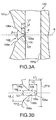
- FIG.3A and FIG.3B are enlarged views of a fracture starting point groove of the large end portion
- FIG.4 illustrates amethod of fracturing and splitting the large endportion.
- reference numeral 100 denotes a split type connecting rod of the present preferred embodiment, which is preferably a nut-less type of connecting rod formed by forging, casting or sintering, or other suitable process.
- This split type connecting rod 100 is provided with a small end 101c having a piston-pin hole 101b at one end of a rod body 101a and a large end portion 101e having a crank-pin hole 101d at the other end.
- the large end portion 101e is provided with shoulders 101f which extend rightward and leftward from the connection with the rod body 101a, and the crank-pin hole 101d is formed at the central portion between both shoulders 101f. Furthermore, bolt holes 101g which extend from the underside to the vicinity of the topside of the large end portion 101e are formed in the shoulders 101f.
- a rod portion 102 and a cap portion 103 are preferably integral and define a single, unitary structure that is formed beforehand and the entire split type connecting rod 100 including the large end portion 101e is subjected to surface hardening treatment such as carburization and tempering.
- the large end portion 101e is fractured and split into a rod portion 102 and cap portion 103 along a predetermined fracture plane (straight line A in the figure).
- Fracturing and splitting into the rod portion 102 and cap portion 103 is performed as shown in FIG. 4 by placing the split type connecting rod 100 on a base 110, inserting sliders 111 which are movable in the diameter direction into the crank-pin hole 101d of the large end portion 101e and driving a wedge 112 between both sliders 111.
- a surface hardened layer having a predetermined carburization depth is formedon the outer surface of the split type connecting rod 100.
- the surface hardening treatment not only carburization and tempering but also nitriding, thermal spraying, vapor deposition or high-frequency quenching, or other suitable process, can be used.
- a pair of fracture starting point grooves 105 which extend in the shaft center direction of the crank-pin hole 101d are preferably formed.
- the fracture starting point grooves 105 are preferably formed by notching through cutting, wire cutting (wire cutting electric discharge machining) or machining using a las er, or other suitable process, and are formed along a line of intersection between the plane that will definef a fracture plane (expre s sed by straight line A in the figure) between the rod portion 102 and cap portion 103 of the large end portion 101e, and the inner circumferential surface. That is, in the case of forming the fracture starting point grooves 105 by, e.g.
- a conductive wire is placed near a predetermined position of the inner circumferential surface of the crank-pin hole 101d and a pulsed high voltage is applied between this conductive wire and the inner circumferential surface of the crank-pin hole 101d.
- a valley 106 is formed between the inner circumferential surface of the crank-pin hole 101d and the fracture starting point grooves 105.
- the valley 106 is formed by chamfering upper and lower corners which are formed by the fracture starting point grooves 105 and the inner circumferential surface of the crank-pin hole 101d.
- the opening of the valley 106 is preferably wider than the opening of the fracture starting point grooves 105.
- This valley 106 is preferably formed through machining such as wire cutting as with the fracture starting point grooves 105 or simultaneously with molding of the split type connecting rod 100 through forging, casting or sintering, or other suitable process.
- sloped portions 106a making up the valley 106 are preferably formed by linear notching in such a way that an angle ⁇ formed with the straight line A (a plane that will def ine a fracture plane) passing from the shaft center a of the crank-pin hole 101d through a bottom portion 105a in a bottom surface 105c of the fracture starting point grooves 105 is preferably about 45 degrees. This causes the interior angle of the valley 106 to be approximately 90 degrees. Furthermore, upper and lower inner surfaces 105b of the fracture starting point groove 105 are formed in such a way that an angle ⁇ formed with the straight line A is approximately 0 degrees, that is, substantially parallel to the straight line A.
- the valley 106 preferably has a greater opening width L4 than an opening width L3 of the fracture starting point groove 105. This causes the sloped portions 106a making up the valley 106 to function as chamfers when a bi-partitioned metal bearing (not shown) is inserted into the crank-pin hole 101d in the direction of the bolt hole 101g.
- the chamfering function of the slopedportions 106a will be explained.
- Metal plating such as Sn (tin) plating is applied to the surface of the metal bearing as an anti-corrosion layer.
- Sn (tin) plating is applied to the surface of the metal bearing as an anti-corrosion layer.
- the ratio of the depth L2 of the fracture starting point groove 105 to a shortest distance L1 from the base point of the fracture starting point groove 105 (that is, a boundary 107 between the inner surface 105b and sloped portion 106a) to the edge of the bolt hole 101g is preferably about 70% or above.
- a pair of fracture starting point grooves 105 which extend in the inner circumferential surface of the crank-pin hole 101d in the shaft center direction are formed, sloped portions 106a are formed in the upper and lower corners between the fracture starting point groove 105 and the inner circumferential surface of the crank-pin hole 101d.
- the valley 106 preferably has an opening width L4 that is wider than the opening width L3 of the fracture starting point groove 105.
- the angle ⁇ formed by the valley 106 and the straight line A is prefer ably greater than the angle ⁇ formed by the fracture starting point groove 105.
- FIG.5A, FIG.5B, FIG. 6 and FIG.7 illustrate a split type connecting rod according to a second preferred embodiment of the present invention.
- FIG.5A is a front view of the split type connecting rod of this embodiment
- FIG.5B is a cross-sectional view of the split type connecting rod shown in FIG.5A along a line V-V
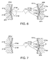
- FIG.6 is a cross-sectional view of the split type connecting rod shown in FIG.5B along a line VI-VI
- FIG.7 is a cross-sectional view of the split type connecting rod shown in FIG.5B along a line VII-VII.
- the split type connecting rod which will be explained in this preferred embodiment preferably has a basic configuration similar to that of the split type connecting rod 100 explained in the first preferred embodiment and identical components or components corresponding to each other between the two preferred embodiments are assigned the same reference numerals and detailed explanations thereof will be omitted.
- a split type connecting rod 200 in this preferred embodiment is provided with a substantially ring-shaped metal bearing 213 on the inner circumferential surface of a crank-pin hole 101d.
- This metal bearing 213 is split into two portions of a rod-side metal bearing portion 213a and a cap-side metal bearing portion 213b along splitting lines on which the fracture plane (straight line A) and the crank-pin hole 101d cross each other. That is, fracture starting point grooves 105 and the rod-side metal bearing portion 213a and the cap-side metal bearing portion 213b each preferably have a substantially semicircular shape.
- bearing locking grooves 201h and 201i are provided on the one splitting line side of the inner circumferential surface of the crank-pin hole 101d, while bearing locking grooves 201h' and 201i' are provided on the other splitting line side.
- the bearing locking grooves 201h, 201h', 201i, 201i' are preferably formed by revolving a grooving cutter T which is placed in such a way as to be inscribed in the crank-pin hole 101d and cutting to a predetermined depth.
- the bearing locking grooves 201h, 201h', 201i, 201i' are preferably arc-shaped when viewed in the shaft center direction of the crank-pinhole 101d (see FIG. 6 and FIG. 7).
- the bearing locking grooves 201h, 201h', 201i, 201i' are formed so as to extend over the splitting line in the circumferential direction and so as to deviate to either side of the splitting line in the circumferential direction (see FIG.5B). More specifically, the bearing locking grooves 201h, 201h' deviate to the rod portion 102 side, while the bearing locking grooves 201i, 201i' deviate to the cap portion 103 side.
- the bearing locking groove 201h is formed so as to deviate to the rod portion 102 side, while the bearing locking groove 201i is formed so as to deviate to the cap portion 103 side.
- the bearing locking groove 201h', 201i' juxtaposed to each other in the shaft center direction of the crank-pin hole 101d is formed so as to deviate to the rod portion 102 side, while the bearing locking groove 201i' is formed so as to deviate to the cap portion 103 side.
- locking lugs 213c, 213c' are provided on the back of both ends 213a' of the substantially semi-circular rod-side metal bearing portion 213a
- locking lugs 213d, 213d' are provided on the back of both ends 213b' of the substantially semi-circular cap-side metal bearing portion 213b.
- the locking lugs 213c are locked by the bearing locking grooves 201h, 201i formed on the split type connecting rod 200 side, while the locking lugs 213c' are locked by thebearing locking grooves 201h', 201i' formed on the split type connecting rod 200 side.
- the locking lugs 213d are locked by the bearing locking grooves 201h, 201i formed on the split type connecting rod 200 side, while the locking lugs 213d' are locked by the bearing locking grooves 201h', 201i' formed on the split type connecting rod 200 side.
- the bearing locking grooves 201h, 201h', 201i, 201i' are deviated to either side of the splitting line in the circumferential direction, the locking lugs 213c, 213c' of the rod-side metal bearing portion 213a are locked at the ends on the rod portion 102 side of the bearing locking grooves 201i, 201i' deviated to the cap portion 103 side.
- the locking lugs 213d, 213d' of the cap-side metal bearing portion 213b are locked at the ends on the cap portion 103 of the bearing locking grooves 201h, 201h' deviated to the rod portion 102 side.
- the locking lugs 213c. 213c' of the rod-side metal bearing portion 213a are locked at the end of the bearing locking grooves 201i, 201i' and the locking lugs 213d, 213d' of the cap-side metal bearing portion 213b are locked at the end of the bearing locking grooves 201h, 201h' , and therefore it is possible to prevent the rod-side metal bearing portion 213a and cap-side metal bearing portion 213b from moving in the circumferential direction.
- the bearing locking grooves 201h, 201h', 201i, 201i' are deviated in the circumferential direction, it is possible to lock the locking lugs 213c, 213c', 213d, 213d' at the end of the bearing locking grooves 201h, 201h', 201i, 201i' without reducing the diameter of the grooving cutter T, that is, the diameters of the bearing locking grooves 201h, 201h', 201i, 201i'. It is also possible to avoid the problem of stress concentration caused by reducing the diameters of the bearing locking grooves 201h, 201h', 201i, 201i'.
- the bearing locking grooves are preferably formed on both splitting lines, but the bearing locking grooves of various preferred embodiments of the present invention may be formed only on one splitting line. That is, as shown in FIG.6 and FIG.7, this preferred embodiment assumes that the locking lugs 213c, 213c' protrude from both ends 213a' of the rod-side metal bearing portion 213a and the locking lugs 213d, 213d' protrude from both ends 213b' of the cap-side metal bearing portion 213b.
- FIG.8 is a perspective view of one example of the cap-side metal bearing portion 213b from which one locking lug 213d protrudes for only one of both ends 213b'.
- FIG.9 is a perspective view of the split type connecting rod 200 when this cap-side me tal bearing portion 213b is attached.
- the locking lug 213d of the cap-side metal 213b is locked by the bearing locking groove 201h provided on the inner circumferential surface of the crank-pin hole 101d.
- the rod-side metal bearing portion 213a where one locking lug 213c is provided on one of the two ends 213a' so as to be locked by the bearing locking groove 201i is also attached together. Therefore, it is possible to stop rotation in the circumferential direction of the rod-side metal bearing portion 213a and cap-side metal bearing portion 213b.
Landscapes
- Engineering & Computer Science (AREA)
- General Engineering & Computer Science (AREA)
- Mechanical Engineering (AREA)
- Shafts, Cranks, Connecting Bars, And Related Bearings (AREA)
- Joining Of Building Structures In Genera (AREA)
- Load-Engaging Elements For Cranes (AREA)
Applications Claiming Priority (4)
| Application Number | Priority Date | Filing Date | Title |
|---|---|---|---|
| JP2002378020 | 2002-12-26 | ||
| JP2002378020 | 2002-12-26 | ||
| JP2003315615 | 2003-09-08 | ||
| JP2003315615 | 2003-09-08 |
Publications (3)
| Publication Number | Publication Date |
|---|---|
| EP1433965A2 true EP1433965A2 (de) | 2004-06-30 |
| EP1433965A3 EP1433965A3 (de) | 2006-05-17 |
| EP1433965B1 EP1433965B1 (de) | 2009-10-14 |
Family
ID=32473741
Family Applications (1)
| Application Number | Title | Priority Date | Filing Date |
|---|---|---|---|
| EP03029941A Expired - Lifetime EP1433965B1 (de) | 2002-12-26 | 2003-12-29 | Pleuel mit einem geteilten Pleuelstangenkopf |
Country Status (6)
| Country | Link |
|---|---|
| US (2) | US7299716B2 (de) |
| EP (1) | EP1433965B1 (de) |
| CN (1) | CN100373061C (de) |
| AT (1) | ATE445787T1 (de) |
| DE (1) | DE60329652D1 (de) |
| TW (1) | TWI235208B (de) |
Families Citing this family (14)
| Publication number | Priority date | Publication date | Assignee | Title |
|---|---|---|---|---|
| JP2005308189A (ja) * | 2004-04-26 | 2005-11-04 | Honda Motor Co Ltd | コネクティングロッド及びその製造方法 |
| JP2006300081A (ja) * | 2005-04-15 | 2006-11-02 | Honda Motor Co Ltd | コンロッドの製造方法 |
| US7757584B2 (en) * | 2005-05-20 | 2010-07-20 | Yamaha Hatsudoki Kabushiki Kaisha | Connecting rod and internal combustion engine and automotive vehicle incorporating the same |
| MX2011009552A (es) * | 2009-03-16 | 2011-10-12 | Kessler Kg Maschf | Metodo para unir dos componentes de una unidad. |
| JP2011183529A (ja) * | 2010-03-10 | 2011-09-22 | Suzuki Motor Corp | コンロッド破断分割装置及び破断分割方法 |
| DE102010012476A1 (de) * | 2010-03-24 | 2011-09-29 | Schaeffler Technologies Gmbh & Co. Kg | Trennbare Laufbahnhülsen |
| JP5703991B2 (ja) * | 2011-06-24 | 2015-04-22 | スズキ株式会社 | コンロッドの破断分割方法及びその装置 |
| JP6145301B2 (ja) * | 2013-05-14 | 2017-06-07 | 株式会社安永 | コンロッドの破断開始部形成方法及び形成装置 |
| TWM519178U (zh) * | 2014-05-20 | 2016-03-21 | 昱曦機械高新科技有限公司 | 往復式內燃機及活塞汽缸連桿總成 |
| CN104196872A (zh) * | 2014-07-28 | 2014-12-10 | 朱德仲 | 一种用于密闭容器装置上的摆杆机构 |
| US10618103B2 (en) * | 2015-11-20 | 2020-04-14 | Caterpillar Inc. | Method for non-linear fracture splitting |
| US10018221B2 (en) * | 2015-11-24 | 2018-07-10 | Brp-Rotax Gmbh & Co. Kg | Fracture-separated engine component and method for manufacturing same |
| USD801151S1 (en) | 2016-07-08 | 2017-10-31 | Race Winning Brands, Inc. | I-beam connecting rod |
| USD904754S1 (en) * | 2018-11-30 | 2020-12-15 | William Prym Gmbh & Co. Kg | Pompon maker |
Citations (1)
| Publication number | Priority date | Publication date | Assignee | Title |
|---|---|---|---|---|
| JPH0674237A (ja) | 1992-08-26 | 1994-03-15 | Toyota Motor Corp | 内燃機関の軸受構造 |
Family Cites Families (15)
| Publication number | Priority date | Publication date | Assignee | Title |
|---|---|---|---|---|
| US3390925A (en) * | 1966-04-19 | 1968-07-02 | Caterpillar Tractor Co | Connecting rod with strap type cap |
| US3576353A (en) | 1969-04-25 | 1971-04-27 | Caterpillar Tractor Co | Connecting rod bearing |
| US3679244A (en) * | 1970-09-21 | 1972-07-25 | Robert R Reddy | Releasable shaft lock |
| FR2371599A1 (fr) * | 1974-05-16 | 1978-06-16 | Rolls Royce Motors Ltd | Palier de tete de bielle de moteur |
| JPS5438246B2 (de) * | 1975-01-29 | 1979-11-20 | ||
| JPS55161918U (de) * | 1979-05-09 | 1980-11-20 | ||
| JPS5844890B2 (ja) | 1981-07-30 | 1983-10-06 | ヤマハ発動機株式会社 | エンジンの連接棒半成品 |
| US4569109A (en) | 1984-07-02 | 1986-02-11 | General Motors Corporation | Method of making a split bearing assembly |
| JPS6182016A (ja) | 1984-09-14 | 1986-04-25 | Honda Motor Co Ltd | 往復動機関の連接棒 |
| US4567815A (en) * | 1984-12-04 | 1986-02-04 | Vilter Manufacturing Corporation | Connecting rod and bearing assembly therefor |
| DE3618742A1 (de) | 1986-06-04 | 1987-12-10 | Glyco Metall Werke | Radialgleitlager-anordnung, insbesondere pleuellager |
| US5208979A (en) | 1991-09-19 | 1993-05-11 | Howard Schmidt | Prefracture laser formation of a stress riser groove |
| DE19531365C2 (de) | 1995-08-25 | 1998-11-05 | Knorr Bremse Systeme | Verfahren zur Herstellung einer Pleuelstange, insbesondere für Kompressoren |
| JPH10128481A (ja) | 1996-10-25 | 1998-05-19 | Honda Motor Co Ltd | コネクティングロッドの製造方法 |
| JP2000179535A (ja) | 1998-12-16 | 2000-06-27 | Honda Motor Co Ltd | 分割型コンロッドにおける軸受メタルの位置決め構造 |
-
2003
- 2003-12-23 US US10/743,457 patent/US7299716B2/en not_active Expired - Lifetime
- 2003-12-25 TW TW092136883A patent/TWI235208B/zh not_active IP Right Cessation
- 2003-12-26 CN CNB2003101244753A patent/CN100373061C/zh not_active Expired - Lifetime
- 2003-12-29 DE DE60329652T patent/DE60329652D1/de not_active Expired - Lifetime
- 2003-12-29 EP EP03029941A patent/EP1433965B1/de not_active Expired - Lifetime
- 2003-12-29 AT AT03029941T patent/ATE445787T1/de not_active IP Right Cessation
-
2007
- 2007-10-19 US US11/875,176 patent/US20080047393A1/en not_active Abandoned
Patent Citations (1)
| Publication number | Priority date | Publication date | Assignee | Title |
|---|---|---|---|---|
| JPH0674237A (ja) | 1992-08-26 | 1994-03-15 | Toyota Motor Corp | 内燃機関の軸受構造 |
Also Published As
| Publication number | Publication date |
|---|---|
| EP1433965A3 (de) | 2006-05-17 |
| ATE445787T1 (de) | 2009-10-15 |
| US20080047393A1 (en) | 2008-02-28 |
| TW200424449A (en) | 2004-11-16 |
| DE60329652D1 (de) | 2009-11-26 |
| CN1512083A (zh) | 2004-07-14 |
| EP1433965B1 (de) | 2009-10-14 |
| US20040159178A1 (en) | 2004-08-19 |
| CN100373061C (zh) | 2008-03-05 |
| TWI235208B (en) | 2005-07-01 |
| US7299716B2 (en) | 2007-11-27 |
Similar Documents
| Publication | Publication Date | Title |
|---|---|---|
| US20080047393A1 (en) | Split type connecting rod | |
| EP1433964B1 (de) | Pleuel mit einem geteilten Pleuelstangenkopf | |
| US4693139A (en) | Connecting rod of reciprocating motion system and method for producing the same | |
| JP2004052775A (ja) | コンロッドの破断分割構造 | |
| EP2438315B1 (de) | Schmiervertiefung einer pleuelstange | |
| US7757584B2 (en) | Connecting rod and internal combustion engine and automotive vehicle incorporating the same | |
| JP2000179535A (ja) | 分割型コンロッドにおける軸受メタルの位置決め構造 | |
| EP1538352B1 (de) | Pleuel mit einem geteilten Pleuelstangenkopf und entsprechendes Herstellungsverfahren | |
| EP0248484A2 (de) | Lager | |
| EP1769866B9 (de) | Eisenvorformteil | |
| US20060002643A1 (en) | Bearing shell, bearing, and method for the production of bearing shells | |
| CN100390427C (zh) | 连杆的断裂分切结构 | |
| JP4452073B2 (ja) | 破断分割型コンロッド、これを有するエンジン及び車両 | |
| JP2005106271A (ja) | 分割型コンロッド | |
| EP1769865B1 (de) | Eisenvorformteil | |
| EP1870567B1 (de) | Kipphebel | |
| JP4799047B2 (ja) | コンロッドおよびそれを備えた内燃機関ならびに自動車両 | |
| JPH05196030A (ja) | コネクティングロッド | |
| JPS58138214A (ja) | 自動車用エンジンのカムシヤフト | |
| EP0773853A1 (de) | Verfahren zur herstellung einer pleuelstange | |
| JPH06264990A (ja) | カムシャフト |
Legal Events
| Date | Code | Title | Description |
|---|---|---|---|
| PUAI | Public reference made under article 153(3) epc to a published international application that has entered the european phase |
Free format text: ORIGINAL CODE: 0009012 |
|
| AK | Designated contracting states |
Kind code of ref document: A2 Designated state(s): AT BE BG CH CY CZ DE DK EE ES FI FR GB GR HU IE IT LI LU MC NL PT RO SE SI SK TR |
|
| AX | Request for extension of the european patent |
Extension state: AL LT LV MK |
|
| PUAL | Search report despatched |
Free format text: ORIGINAL CODE: 0009013 |
|
| AK | Designated contracting states |
Kind code of ref document: A3 Designated state(s): AT BE BG CH CY CZ DE DK EE ES FI FR GB GR HU IE IT LI LU MC NL PT RO SE SI SK TR |
|
| AX | Request for extension of the european patent |
Extension state: AL LT LV MK |
|
| RIC1 | Information provided on ipc code assigned before grant |
Ipc: F16C 9/04 20060101AFI20040405BHEP |
|
| 17P | Request for examination filed |
Effective date: 20060711 |
|
| AKX | Designation fees paid |
Designated state(s): AT BE BG CH CY CZ DE DK EE ES FI FR GB GR HU IE IT LI LU MC NL PT RO SE SI SK TR |
|
| 17Q | First examination report despatched |
Effective date: 20070109 |
|
| GRAP | Despatch of communication of intention to grant a patent |
Free format text: ORIGINAL CODE: EPIDOSNIGR1 |
|
| GRAS | Grant fee paid |
Free format text: ORIGINAL CODE: EPIDOSNIGR3 |
|
| GRAA | (expected) grant |
Free format text: ORIGINAL CODE: 0009210 |
|
| AK | Designated contracting states |
Kind code of ref document: B1 Designated state(s): AT BE BG CH CY CZ DE DK EE ES FI FR GB GR HU IE IT LI LU MC NL PT RO SE SI SK TR |
|
| REG | Reference to a national code |
Ref country code: GB Ref legal event code: FG4D |
|
| REG | Reference to a national code |
Ref country code: CH Ref legal event code: EP |
|
| REG | Reference to a national code |
Ref country code: IE Ref legal event code: FG4D |
|
| REF | Corresponds to: |
Ref document number: 60329652 Country of ref document: DE Date of ref document: 20091126 Kind code of ref document: P |
|
| NLV1 | Nl: lapsed or annulled due to failure to fulfill the requirements of art. 29p and 29m of the patents act | ||
| PG25 | Lapsed in a contracting state [announced via postgrant information from national office to epo] |
Ref country code: SE Free format text: LAPSE BECAUSE OF FAILURE TO SUBMIT A TRANSLATION OF THE DESCRIPTION OR TO PAY THE FEE WITHIN THE PRESCRIBED TIME-LIMIT Effective date: 20091014 Ref country code: PT Free format text: LAPSE BECAUSE OF FAILURE TO SUBMIT A TRANSLATION OF THE DESCRIPTION OR TO PAY THE FEE WITHIN THE PRESCRIBED TIME-LIMIT Effective date: 20100215 Ref country code: FI Free format text: LAPSE BECAUSE OF FAILURE TO SUBMIT A TRANSLATION OF THE DESCRIPTION OR TO PAY THE FEE WITHIN THE PRESCRIBED TIME-LIMIT Effective date: 20091014 Ref country code: ES Free format text: LAPSE BECAUSE OF FAILURE TO SUBMIT A TRANSLATION OF THE DESCRIPTION OR TO PAY THE FEE WITHIN THE PRESCRIBED TIME-LIMIT Effective date: 20100125 |
|
| PG25 | Lapsed in a contracting state [announced via postgrant information from national office to epo] |
Ref country code: SI Free format text: LAPSE BECAUSE OF FAILURE TO SUBMIT A TRANSLATION OF THE DESCRIPTION OR TO PAY THE FEE WITHIN THE PRESCRIBED TIME-LIMIT Effective date: 20091014 |
|
| PG25 | Lapsed in a contracting state [announced via postgrant information from national office to epo] |
Ref country code: BE Free format text: LAPSE BECAUSE OF FAILURE TO SUBMIT A TRANSLATION OF THE DESCRIPTION OR TO PAY THE FEE WITHIN THE PRESCRIBED TIME-LIMIT Effective date: 20091014 Ref country code: AT Free format text: LAPSE BECAUSE OF FAILURE TO SUBMIT A TRANSLATION OF THE DESCRIPTION OR TO PAY THE FEE WITHIN THE PRESCRIBED TIME-LIMIT Effective date: 20091014 |
|
| PG25 | Lapsed in a contracting state [announced via postgrant information from national office to epo] |
Ref country code: RO Free format text: LAPSE BECAUSE OF FAILURE TO SUBMIT A TRANSLATION OF THE DESCRIPTION OR TO PAY THE FEE WITHIN THE PRESCRIBED TIME-LIMIT Effective date: 20091014 Ref country code: MC Free format text: LAPSE BECAUSE OF NON-PAYMENT OF DUE FEES Effective date: 20100701 Ref country code: DK Free format text: LAPSE BECAUSE OF FAILURE TO SUBMIT A TRANSLATION OF THE DESCRIPTION OR TO PAY THE FEE WITHIN THE PRESCRIBED TIME-LIMIT Effective date: 20091014 Ref country code: EE Free format text: LAPSE BECAUSE OF FAILURE TO SUBMIT A TRANSLATION OF THE DESCRIPTION OR TO PAY THE FEE WITHIN THE PRESCRIBED TIME-LIMIT Effective date: 20091014 Ref country code: BG Free format text: LAPSE BECAUSE OF FAILURE TO SUBMIT A TRANSLATION OF THE DESCRIPTION OR TO PAY THE FEE WITHIN THE PRESCRIBED TIME-LIMIT Effective date: 20100114 |
|
| REG | Reference to a national code |
Ref country code: CH Ref legal event code: PL |
|
| PLBE | No opposition filed within time limit |
Free format text: ORIGINAL CODE: 0009261 |
|
| STAA | Information on the status of an ep patent application or granted ep patent |
Free format text: STATUS: NO OPPOSITION FILED WITHIN TIME LIMIT |
|
| PG25 | Lapsed in a contracting state [announced via postgrant information from national office to epo] |
Ref country code: SK Free format text: LAPSE BECAUSE OF FAILURE TO SUBMIT A TRANSLATION OF THE DESCRIPTION OR TO PAY THE FEE WITHIN THE PRESCRIBED TIME-LIMIT Effective date: 20091014 Ref country code: CZ Free format text: LAPSE BECAUSE OF FAILURE TO SUBMIT A TRANSLATION OF THE DESCRIPTION OR TO PAY THE FEE WITHIN THE PRESCRIBED TIME-LIMIT Effective date: 20091014 |
|
| 26N | No opposition filed |
Effective date: 20100715 |
|
| PG25 | Lapsed in a contracting state [announced via postgrant information from national office to epo] |
Ref country code: GR Free format text: LAPSE BECAUSE OF FAILURE TO SUBMIT A TRANSLATION OF THE DESCRIPTION OR TO PAY THE FEE WITHIN THE PRESCRIBED TIME-LIMIT Effective date: 20100115 Ref country code: IE Free format text: LAPSE BECAUSE OF NON-PAYMENT OF DUE FEES Effective date: 20091229 Ref country code: LI Free format text: LAPSE BECAUSE OF NON-PAYMENT OF DUE FEES Effective date: 20091231 Ref country code: CH Free format text: LAPSE BECAUSE OF NON-PAYMENT OF DUE FEES Effective date: 20091231 |
|
| PG25 | Lapsed in a contracting state [announced via postgrant information from national office to epo] |
Ref country code: IT Free format text: LAPSE BECAUSE OF FAILURE TO SUBMIT A TRANSLATION OF THE DESCRIPTION OR TO PAY THE FEE WITHIN THE PRESCRIBED TIME-LIMIT Effective date: 20091014 |
|
| PG25 | Lapsed in a contracting state [announced via postgrant information from national office to epo] |
Ref country code: LU Free format text: LAPSE BECAUSE OF NON-PAYMENT OF DUE FEES Effective date: 20091229 |
|
| PG25 | Lapsed in a contracting state [announced via postgrant information from national office to epo] |
Ref country code: HU Free format text: LAPSE BECAUSE OF FAILURE TO SUBMIT A TRANSLATION OF THE DESCRIPTION OR TO PAY THE FEE WITHIN THE PRESCRIBED TIME-LIMIT Effective date: 20100415 |
|
| PG25 | Lapsed in a contracting state [announced via postgrant information from national office to epo] |
Ref country code: TR Free format text: LAPSE BECAUSE OF FAILURE TO SUBMIT A TRANSLATION OF THE DESCRIPTION OR TO PAY THE FEE WITHIN THE PRESCRIBED TIME-LIMIT Effective date: 20091014 |
|
| PG25 | Lapsed in a contracting state [announced via postgrant information from national office to epo] |
Ref country code: CY Free format text: LAPSE BECAUSE OF FAILURE TO SUBMIT A TRANSLATION OF THE DESCRIPTION OR TO PAY THE FEE WITHIN THE PRESCRIBED TIME-LIMIT Effective date: 20091014 |
|
| PG25 | Lapsed in a contracting state [announced via postgrant information from national office to epo] |
Ref country code: NL Free format text: LAPSE BECAUSE OF FAILURE TO SUBMIT A TRANSLATION OF THE DESCRIPTION OR TO PAY THE FEE WITHIN THE PRESCRIBED TIME-LIMIT Effective date: 20091014 |
|
| REG | Reference to a national code |
Ref country code: FR Ref legal event code: PLFP Year of fee payment: 13 |
|
| REG | Reference to a national code |
Ref country code: FR Ref legal event code: PLFP Year of fee payment: 14 |
|
| REG | Reference to a national code |
Ref country code: FR Ref legal event code: PLFP Year of fee payment: 15 |
|
| PGFP | Annual fee paid to national office [announced via postgrant information from national office to epo] |
Ref country code: GB Payment date: 20201223 Year of fee payment: 18 |
|
| GBPC | Gb: european patent ceased through non-payment of renewal fee |
Effective date: 20211229 |
|
| PG25 | Lapsed in a contracting state [announced via postgrant information from national office to epo] |
Ref country code: GB Free format text: LAPSE BECAUSE OF NON-PAYMENT OF DUE FEES Effective date: 20211229 |
|
| PGFP | Annual fee paid to national office [announced via postgrant information from national office to epo] |
Ref country code: FR Payment date: 20221222 Year of fee payment: 20 Ref country code: DE Payment date: 20221213 Year of fee payment: 20 |
|
| P01 | Opt-out of the competence of the unified patent court (upc) registered |
Effective date: 20230527 |
|
| REG | Reference to a national code |
Ref country code: DE Ref legal event code: R071 Ref document number: 60329652 Country of ref document: DE |