EP1433533A1 - Dispositif de distribution comportant des moyens permettant de distribuer deux produits dans des proportions variables - Google Patents
Dispositif de distribution comportant des moyens permettant de distribuer deux produits dans des proportions variables Download PDFInfo
- Publication number
- EP1433533A1 EP1433533A1 EP20030293209 EP03293209A EP1433533A1 EP 1433533 A1 EP1433533 A1 EP 1433533A1 EP 20030293209 EP20030293209 EP 20030293209 EP 03293209 A EP03293209 A EP 03293209A EP 1433533 A1 EP1433533 A1 EP 1433533A1
- Authority
- EP
- European Patent Office
- Prior art keywords
- control member
- product
- push button
- pump
- elastically deformable
- Prior art date
- Legal status (The legal status is an assumption and is not a legal conclusion. Google has not performed a legal analysis and makes no representation as to the accuracy of the status listed.)
- Granted
Links
Images

Classifications
-
- B—PERFORMING OPERATIONS; TRANSPORTING
- B65—CONVEYING; PACKING; STORING; HANDLING THIN OR FILAMENTARY MATERIAL
- B65D—CONTAINERS FOR STORAGE OR TRANSPORT OF ARTICLES OR MATERIALS, e.g. BAGS, BARRELS, BOTTLES, BOXES, CANS, CARTONS, CRATES, DRUMS, JARS, TANKS, HOPPERS, FORWARDING CONTAINERS; ACCESSORIES, CLOSURES, OR FITTINGS THEREFOR; PACKAGING ELEMENTS; PACKAGES
- B65D81/00—Containers, packaging elements, or packages, for contents presenting particular transport or storage problems, or adapted to be used for non-packaging purposes after removal of contents
- B65D81/32—Containers, packaging elements, or packages, for contents presenting particular transport or storage problems, or adapted to be used for non-packaging purposes after removal of contents for packaging two or more different materials which must be maintained separate prior to use in admixture
- B65D81/3283—Cylindrical or polygonal containers, e.g. bottles, with two or more substantially axially offset, side-by-side compartments for simultaneous dispensing
- B65D81/3288—Cylindrical or polygonal containers, e.g. bottles, with two or more substantially axially offset, side-by-side compartments for simultaneous dispensing composed of two or more separate containers joined to each other
-
- B—PERFORMING OPERATIONS; TRANSPORTING
- B05—SPRAYING OR ATOMISING IN GENERAL; APPLYING FLUENT MATERIALS TO SURFACES, IN GENERAL
- B05B—SPRAYING APPARATUS; ATOMISING APPARATUS; NOZZLES
- B05B11/00—Single-unit hand-held apparatus in which flow of contents is produced by the muscular force of the operator at the moment of use
- B05B11/01—Single-unit hand-held apparatus in which flow of contents is produced by the muscular force of the operator at the moment of use characterised by the means producing the flow
- B05B11/10—Pump arrangements for transferring the contents from the container to a pump chamber by a sucking effect and forcing the contents out through the dispensing nozzle
- B05B11/1081—Arrangements for pumping several liquids or other fluent materials from several containers, e.g. for mixing them at the moment of pumping
- B05B11/1083—Arrangements for pumping several liquids or other fluent materials from several containers, e.g. for mixing them at the moment of pumping in adjustable proportion
-
- B—PERFORMING OPERATIONS; TRANSPORTING
- B05—SPRAYING OR ATOMISING IN GENERAL; APPLYING FLUENT MATERIALS TO SURFACES, IN GENERAL
- B05B—SPRAYING APPARATUS; ATOMISING APPARATUS; NOZZLES
- B05B11/00—Single-unit hand-held apparatus in which flow of contents is produced by the muscular force of the operator at the moment of use
- B05B11/01—Single-unit hand-held apparatus in which flow of contents is produced by the muscular force of the operator at the moment of use characterised by the means producing the flow
- B05B11/10—Pump arrangements for transferring the contents from the container to a pump chamber by a sucking effect and forcing the contents out through the dispensing nozzle
- B05B11/1081—Arrangements for pumping several liquids or other fluent materials from several containers, e.g. for mixing them at the moment of pumping
- B05B11/1084—Arrangements for pumping several liquids or other fluent materials from several containers, e.g. for mixing them at the moment of pumping each liquid or other fluent material being pumped by a separate pump
-
- Y—GENERAL TAGGING OF NEW TECHNOLOGICAL DEVELOPMENTS; GENERAL TAGGING OF CROSS-SECTIONAL TECHNOLOGIES SPANNING OVER SEVERAL SECTIONS OF THE IPC; TECHNICAL SUBJECTS COVERED BY FORMER USPC CROSS-REFERENCE ART COLLECTIONS [XRACs] AND DIGESTS
- Y10—TECHNICAL SUBJECTS COVERED BY FORMER USPC
- Y10T—TECHNICAL SUBJECTS COVERED BY FORMER US CLASSIFICATION
- Y10T137/00—Fluid handling
- Y10T137/0318—Processes
- Y10T137/0324—With control of flow by a condition or characteristic of a fluid
- Y10T137/0368—By speed of fluid
Definitions
- the present invention relates to dispensing devices comprising means for distributing two products in variable proportions.
- European patent EP 758 615 describes an example of a device for have, under the appearance of a single package, several products with indices of different sun protection or a sun protection product and an after-sun such than a moisturizer.
- European patent application EP 427 609 describes a device comprising a regulating member making it possible to vary the proportions of two products taken from respective reservoirs, within a mixture.
- This regulating member is presented under the form of a rotating part allowing to press more or less on a pump rod when a push button is pressed.
- Such a device does not allow, by means of a single adjustment device, to distribute for example only the product contained in one or the other of the tanks.
- US Patent 5,971,210 describes a relatively complex device, comprising a mechanism for transforming an actuation of the push button into longer or shorter actuation strokes of the pump rods.
- VERSADIAL, Toberdorf, Germany also offers a device comprising two pumps, the control members of which are actuated by means of a pivoting disc, integral with the push button and articulated at one end on a adjusting member which can rotate relative to a base part supporting the bodies of pumps.
- the disc more or less pushes the pump control members, which makes it possible to distribute a mixture with the desired relative proportions of the products taken from tanks associated with pumps.
- No such device is provided to use standard pumps and furthermore has a relatively structure complex.
- the transmission member can deform when the control member associated reaches the limit position imposed by the adjuster before the other control member so as to allow the push button to continue to move move and drive said other control member.
- the regulating member can be produced with one or more pieces, possibly mobile with respect to each other.
- the invention makes it possible, by acting on the adjusting member, to vary the stroke in which at least one of the control members is moved when the push button is pressed. It is thus possible to dose at least one of the products in the distributed mixture.
- the device comprises two elastically deformable transmission, arranged so as to each transmit a movement of the push button to an associated control member, for dispensing product, each elastically deformable member being arranged to deform when the associated control member reaches the end of travel position imposed by the adjustment member before the other control member, so as to allow the push-button to continue to move and train said other control member.
- the device may include two actuating members movable relative to with the push button and respectively associated with the two control members, both elastically deformable transmission members being arranged so as to each interpose between a surface of the associated actuating member and the push button.
- Each actuator can include a rod sliding in a tubular guide of the push button and the elastically deformable member associated with this actuator can be arranged around said rod, being for example constituted by a helical spring working in compression.
- the actuators can be connected together by a set of elastically deformable coupling, which can facilitate their manufacture and handling, especially during their installation on the device.
- This coupling assembly may include, for example, flexible arms which connect each actuator to a central rod, these two arms can form a "S" when the coupling part is observed in the axis of the central rod.
- the coupling assembly may include end pieces fixed on the push button, by which the product delivered by the pumps is delivered to the push button.
- the device may include flexible conduits allowing circulation products delivered by the pumps between the actuators and the housings communicating with said tips.
- the pumps used can be standard pumps and each control may include a pump rod, in particular a pump rod allowing the distribution of the product delivered by the pump through an internal channel of the rod.
- Each actuator may include a tip which is mounted at the end of the associated pump rod. This tip can be arranged to allow the connection of a flexible conduit as mentioned above, making it possible to route the product delivered by the pump to a dispensing orifice.
- the elastically deformable member when it is a spring helical, it can be supported at one end on the nozzle and at the other end on the corresponding tubular guide of the push button.
- the adjusting member may include a plurality of surfaces located at different heights and against which the actuators can come to bear when the associated control members have reached their end-of-travel position.
- the different heights can be chosen so that the sum of the strokes on which move the control elements of the two pumps is constant which whatever the position of the adjusting member, for example equal to the maximum stroke of a control unit.
- Said surfaces can each be defined by the upper edge of a tongue.
- the adjusting member is advantageously rotatable, that is to say comprises at minus a rotating part.
- the tongues can be elastically deformable and arranged to deform elastically in contact with at least one control member, during the rotation of the adjusting member, so as to constitute at least one hard point in the rotational movement of the adjusting member, facilitating the positioning of the latter by the user in a position corresponding to a determined mixture. So, the tongues can be arranged so that in a position of the setting corresponding to the distribution of a given mixture, at least one control is arranged between portions of two consecutive tabs which immobilize the adjusting member in rotation.
- Each tab can have a rounded portion into which can come accommodate a control member when the tongue is in a position for adjusting the stroke of this control member.
- the lower edges of the tabs can be located substantially in a same plan.
- Each tab can in particular be arranged to come in the position of adjustment of the stroke of the associated control member, supported by its lower edge against a fixed support surface relative to the body of the corresponding pump.
- the adjusting member may include two coaxial rotary rings comprising tabs making it possible to adjust the end of travel of at least the control associated with the transmission member.
- the crowns can be connected by at least one gear, in particular two gears.
- the tongues may have opposite concavities.
- the push button may have an upper part defining a support surface allowing the user to operate the push button and a skirt elastically deformable extending downward said upper part.
- the device may include an outlet orifice provided with a valve, especially in elastomer.
- the device may include a base part used for mounting the pumps and relative to which the push button is movable.
- This basic part can include at least one relief on which the adjustment member is snapped on, with a possibility of rotation without possibility of axial displacement.
- the base part may include an outer skirt provided with at least one window, in particular two opposite windows, providing access to the regulating member to train it in rotation.
- the adjustment member may include a tubular wall provided with marks, in particular graduations, representative of different compositions of the mixture distributed.
- the reservoirs can be constituted by assembled bottles.
- These bottles can have a generally semicircular cross section.
- the bottles can be assembled at least by a profile on which they are incurred.
- This profile may for example comprise at least two walls forming an angle between them and a bottle can be arranged to come to bear on these walls, so as to be held against the profile.
- At least one bottle may have two grooves in which engage said walls.
- the profile may include a central part of elongated shape, which can extend over at least most of the height of the vials, with on each side longitudinal of this central part two ribs each forming, when the profile is observed in cross section, a "V" open to the outside.
- the profile is advantageously secured to the base part, being for example made in one piece by plastic molding therewith.
- the device can be used for packaging many products cosmetics, pharmaceutical, household and others.
- One of the tanks can contain a sun protection product and the other reservoir a moisturizing product, the regulating member making it possible to vary the proportion of the sun protection product in the mixture and the resulting protection index.
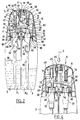
- the device 1 shown in Figures 1 and 2 comprises two bottles 2, 3, each defining a reservoir containing a product P 1 , for example a sun protection product for one of the bottles and a hydrating product P 2 for the other bottle , and a dispensing head 4 comprising a fixed base part 5 and a push button 6 movable relative to the base part.
- This push button 6 is provided in the example considered with a single dispensing orifice, equipped with a valve 7 intended to prevent the entry of sand in particular.
- This valve 7 can be made of elastomer, for example being overmolded on the push button 6.
- the base part 5 has two diametrically opposite windows 9, of which only one of them appears in FIG. 1, giving access to an adjustment member 10 making it possible to adjust the proportions of the products P 1 and P 2 in the mixture distributed.
- the adjusting member 10 is rotatable about the longitudinal axis X of the device 1 in the example considered and comprises a series of graduations 11 allowing the user, by positioning one of them under a reference 12 of the base part 5, of select a specific mixture with the desired protection index, for example.
- the base part 5 has a transverse wall 20 extending perpendicular to the axis X, connecting to its periphery to an outer skirt 21 in which the windows 9 are produced.
- the transverse wall 20 is provided with two openings 22 allowing to accommodate pumps 32 and 33 associated respectively with bottles 2 and 3.
- Each pump which is standard in the example considered comprises a body 34 and a control member 35 consisting of a hollow rod having an internal channel by which the product is dispensed when the rod is pressed into the pump body 34.
- the pumps 32 and 33 are each equipped with a dip tube 36 extending to the bottom of the corresponding tank.
- the base part 5 also includes a mounting skirt 25 provided with a annular bead 26 on which the tabs 27 of the adjusting member can snap 10, in order to allow the latter to be able to rotate around the X axis without moving axially relative to this axis.
- Each pump is fixed to a neck 28 of the corresponding bottle by crimping a metal ring 29, with the interposition of an annular seal 38 between the pump body and upper edge of neck 28.
- the bottles 2 and 3 are fixed on the top of the base part 5 in the example considered by snap-fastening of the collars 28 on lugs 39, which are connected above the transverse wall 20.
- the necks 28 could still be fixed otherwise, for example by screwing or crimping.
- the push button 6 has an upper part 45, relatively rigid, defining a bearing surface 46 for the user, this upper part 45 being made for example of polypropylene, a lower part 47 which can also be made of a relatively rigid plastic material, for example polypropylene, and an intermediate part 48 connecting the upper part 45 to the lower part 47, produced in an elastically deformable material, for example an elastomer such as SEBS.
- the lower part 47 is fixed to the base part 5, for example by snap-fastening.
- the push button 6 comprises tubular guides 50 which are produced in the example considered in one piece by plastic molding with the part upper 45, in which rods 51 can slide, each connecting to its lower end with a nozzle 52 into which the pump rod 35 is inserted corresponding.
- the rods 51 are respectively associated with the two pumps 32 and 33.
- the two end pieces 52 are connected together by a coupling assembly comprising a central rod 53 and arms 54 each connecting an end piece 52 to the rod central 53.
- the two arms 54 have, when the coupling piece is observed in view from above along the X axis, a shape of S that can be seen in Figure 3.
- the rod 53 is connects above to a mounting part 55 on the push button, provided with two tips 56 which are fixed in corresponding housings 58 of the part upper 45 of the push button, these housings 58 communicating via channels respective 59 with the outlet.
- Flexible conduits 60 produced for example in polyethylene, allow the product delivered by each pump rod 35 to be conveyed to a corresponding tip 56, these conduits 60 being inserted at one end into openings provided for this purpose on the end pieces 52, these openings being of axis perpendicular to the axis pump rods 35.
- the nozzles 56 of the coupling assembly are forcibly inserted in the corresponding housings 58 of the upper part 45 of the push button.
- Helical springs 70 working in compression, are arranged on the rods 51, bearing at their upper end against the lower edge 71 of the guides tubular 50 and at their lower end against a shoulder 72 by which each end piece 52 is connected to the corresponding rod 51.
- Each spring 70 allows transmit a displacement of the upper part 45 of the push button in one displacement of the nozzle 52, which serves as an actuating member of the pump rod 35 corresponding.
- the stiffness of the springs 70 is chosen to be large enough for a pushing the push button may result in displacement of the pump rods 35.
- the adjusting member 10 comprises a wall 80, cylindrical of revolution around the X axis in the example considered, on the radially inner surface 81 of which is connected to a plurality of tabs 83 which can be seen in FIG. 3.
- the adjusting member can be produced for example in a deformable material such as POM-C and the coupling part 51, 52, 53, 54 in the same material. We can use also polypropylene.
- the tongues 83 extend radially inwards, obliquely, being inclined in the same circumferential direction. They have at their end a rounded portion having a concavity 86 directed inwards, arranged so as to power, for a given position of the adjusting member 10, come substantially in covering part of the periphery of a pump rod 35, as can be seen in figure 3.
- Two diametrically opposite tongues 83 can be applied simultaneously against the pump rods 35 or at least position themselves in their neighborhood, so as to limit the sinking of the pump rods 35 when the push button 6 is pressed.
- the different tabs 83 have heights which vary from tongue to the other, so that the upper surfaces 90 of the different tongues 83 are not all located in the same plane perpendicular to the X axis.
- the lower surfaces 91 of the tongues 83 are in the same plane.
- the tip 52 can more or less cause it to move, until the stop the lower end of the end piece 52 against the upper surface 90 of the tongue, as seen in Figure 4.
- Each tab 83 associated with a pump rod 35 can also be supported by its lower surface 91 against the body of the pump.
- each pump rod 35 is thus arranged, for a determined adjustment position, between the rounded part 85 of a tongue and the end 94 of the adjacent tongue, having regard to the direction of rotation of the adjusting member 10, which immobilizes the adjusting member 10 in the corresponding position.
- the tongues 83 have, in the example considered, an increasing height for the first seven tabs when we move in the direction of the arrow F then decreasing for the next five tabs.
- the tabs 83 can limit by example the stroke of a pump rod to the following values: 0 mm; 0.65 mm; 1.3 mm; 1.95mm; 2.6 mm; 3.25 mm; 6.5 mm; 5.85 mm; 5.20 mm; 4.5 mm; 3.9 mm.
- the user can press the push button 6 as illustrated in FIG. 4.
- the movement of the push-button 6 is transmitted to the pump rods 35 by the springs 70.
- the spring 70 associated this tip 52 can be compressed to allow the user to continue to push the push-button 6 and the other pump rod 35 to sink until the corresponding tip 52 comes to bear on the associated tongue 83.
- the arms 54 can deform to support the movement of the tips 52.
- the bottles 2 and 3 can be produced in various ways, and in particular be produced by blowing or by injection blowing, preferably being identical.
- vials 2 and 3 can be held together by means of a part elongated 100 as shown in Figure 5, which is in the example illustrated in the form of a profile comprising a central part 101 with on each of its longitudinal sides two pairs of walls 102, 103, 104 and 105, each pair of walls forming a "V".
- the walls 102 and 104 are divergent and the bottle 2 associated with these walls has longitudinal grooves 106 in which the walls 102 and 104 can slide in order to form a dovetail type connection. So is even of the bottle 3, which is held by the walls 103 and 105.
- the profile 100 is advantageously made in one piece by molding plastic with the transverse wall 20 of the base part 5.
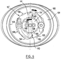
- FIG. 6 shows an alternative embodiment in which the member adjustment 10 is replaced by an adjustment member 10 'comprising two rings 101 and 102 rotary, coaxial axes of rotation X.
- the outermost ring 101 is connected to a wall 105 identical to the wall 80 described above, and has on its inner circumference a plurality of tabs 106 having different heights, concave towards the X axis, arranged to come place under the tips 52, like the tabs 83 described above.
- the crown 102 has at its periphery tongues 108 arranged to come under the end caps 52, on the side opposite the tabs 106.
- Gears 110 and 111 rotating around axes parallel to the X axis mesh with non-visible toothing produced on the crowns 101 and 102, to transmit a rotation of the crown 101 to the crown 102.
- the tongues 108 have heights which correspond to those of the tongues 106, so that the tabs 106 and 108 which come for a given position of the crown 101 is placed under the same end piece 52 have the same height.
- the crossing of the control members 35 by these may be accompanied by a slight elastic deformation of the tabs, which facilitates the positioning of the adjustment 10 'in the desired position.
- another control member for example an elastically deformable membrane, which may have a curved shape, if necessary.
- the coil springs 70 can be replaced by other members of elastically deformable transmission, for example by one or more foam blocks, by flexible tabs or by at least one bridge of an elastomeric material.
Landscapes
- Engineering & Computer Science (AREA)
- Mechanical Engineering (AREA)
- Containers And Packaging Bodies Having A Special Means To Remove Contents (AREA)
Abstract
Description
- deux réservoirs destinés chacun à contenir un produit,
- deux pompes associées respectivement auxdits réservoirs et comportant chacune un organe de commande mobile, dont l'actionnement provoque la distribution du produit contenu dans le réservoir associé par la pompe,
- un bouton-poussoir,
- au moins un organe de transmission élastiquement déformable, associé à un organe de commande, disposé de manière à transmettre un déplacement du bouton-poussoir à cet organe de commande pour distribuer du produit,
- au moins un organe de réglage permettant de régler la position de fin de course de déplacement d'au moins l'organe de commande associé à l'organe de transmission.
- fournir un dispositif tel que défini ci-dessus, ,
- fournir un premier produit dans un premier réservoir du dispositif,
- fournir un deuxième produit dans un deuxième réservoir du disopsotif,
- régler la position de fin de course de déplacement de l'organe de commande associé à l'organe de transmission,
- déplacer le bouton-poussoir et transmettre ce déplacement du bouton-poussoir à l'organe de commande des pompes afin de distribuer les premier et deuxième produits dans une proportion souhaitée.
- la figure 1 est une vue en élévation, schématique, d'un exemple de dispositif réalisé conformément à l'invention,
- la figure 2 est une coupe axiale, schématique et partielle, du dispositif de la figure 1, le bouton-poussoir étant au repos,
- la figure 3 représente schématiquement et partiellement, en vue de dessus, l'organe de réglage notamment,
- la figure 4 est une vue analogue à la figure 2, représentant le bouton-poussoir enfoncé pour distribuer du produit,
- la figure 5 est une coupe transversale schématique selon V-V de la figure 1, et
- la figure 6 est une vue analogue à la figure 3, illustrant une variante de réalisation.
| Positions | Pompe 32 | Pompe 33 |
| 0 | 6.50 | 0.00 |
| 1 | 5.85 | 0.65 |
| 2 | 5.20 | 1.30 |
| 3 | 4.55 | 1.95 |
| 4 | 3.90 | 2.60 |
| 5 | 3.25 | 3.25 |
| 6 | 2.60 | 3.90 |
| 7 | 1.95 | 4.55 |
| 8 | 1.30 | 5.20 |
| 9 | 0.65 | 5.85 |
| 10 | 0.00 | 6.50 |
Claims (40)
- Dispositif de distribution (1), comportant :deux réservoirs (2 ; 3) destinés chacun à contenir un produit (P1; P2),deux pompes (32 ; 33) associées respectivement auxdits réservoirs et comportant chacune un organe de commande (35) mobile, dont l'actionnement provoque la distribution du produit contenu dans le réservoir associé par la pompe,un bouton-poussoir (6),au moins un organe de transmission (70) élastiquement déformable, associé à un organe de commande (35), disposé de manière à transmettre un déplacement du bouton-poussoir (6) à cet organe de commande (35) pour distribuer du produit, etau moins un organe de réglage (10 ; 10') permettant de régler la position de fin de course de déplacement d'au moins l'organe de commande (35) associé à l'organe de transmission (70).
- Dispositif selon la revendication 1, caractérisé par le fait qu'il comporte deux organes de transmission (70) élastiquement déformables, disposés de manière à transmettre chacun un déplacement du bouton-poussoir (6) à un organe de commande (35) associé, pour distribuer du produit, chaque organe élastiquement déformable (70) étant disposé de manière à se déformer lorsque l'organe de commande associé atteint la position de fin de course imposée par l'organe de réglage (10) avant l'autre organe de commande (35), de manière à permettre au bouton-poussoir (6) de continuer à se déplacer et à entraíner ledit autre organe de commande.
- Dispositif selon la revendication précédente, caractérisé par le fait qu'il comporte deux organes d'actionnement (51, 52) mobiles par rapport au bouton-poussoir (6) et respectivement associés aux deux organes de commande (35), les deux organes de transmission (70) élastiquement déformables étant disposés de manière à s'interposer chacun entre une surface (72) de l'organe d'actionnement associé et le bouton-poussoir.
- Dispositif selon la revendication 3, caractérisé par le fait que chaque organe d'actionnement comporte une tige (51) coulissant dans un guide tubulaire (50) du bouton-poussoir et par le fait que l'organe élastiquement déformable (70) associé à cet organe d'actionnement est disposé autour de la tige (51).
- Dispositif selon l'une des revendications 3 et 4, caractérisé par le fait que les organes d'actionnement (51, 52) sont reliés ensemble par un ensemble de couplage (53, 54, 55) élastiquement déformable.
- Dispositif selon la revendication précédente, caractérisé par le fait que l'ensemble de couplage comporte des bras flexibles (54) qui relient chaque organe d'actionnement (51, 52) à une tige centrale (53).
- Dispositif selon la revendication précédente, caractérisé par le fait que les deux bras (54) forment un « S » lorsque l'ensemble de couplage est observé dans l'axe (X) de la tige centrale.
- Dispositif selon l'une quelconque des revendications 5 à 7, caractérisé par le fait que l'ensemble de couplage comporte des embouts (56) fixés sur le bouton-poussoir (6), par lesquels le produit délivré par les pompes (32, 33) est délivré au bouton-poussoir.
- Dispositif selon la revendication précédente, caractérisé par le fait qu'il comporte des conduits flexibles (60) permettant une circulation des produits (P1 ; P2) délivrés par les pompes entre les organes d'actionnement (51, 52) et des logements communiquant avec lesdits embouts.
- Dispositif selon l'une quelconque des revendications précédentes, caractérisé par le fait que chaque organe de commande comporte une tige de pompe (35), notamment une tige de pompe (35) permettant la distribution du produit délivré par la pompe par un canal intérieur de la tige.
- Dispositif selon les revendications 3 et 10, caractérisé par le fait que chaque organe d'actionnement (51, 52) comporte un embout (52) qui est monté à l'extrémité de la tige de pompe (35).
- Dispositif selon la revendication précédente, caractérisé par le fait que l'embout (52) est agencé pour permettre le raccordement d'un conduit flexible (60) permettant d'acheminer le produit délivré par la pompe à un orifice de distribution.
- Dispositif selon les revendications 4 et 11, l'organe élastiquement déformable étant un ressort hélicoïdal (70), caractérisé par le fait que ce ressort (70) prend appui à une extrémité sur l'embout (52) et à l'autre extrémité sur le guide tubulaire (50).
- Dispositif selon la revendication 3, caractérisé par le fait que l'organe de réglage comporte une pluralité de surfaces (90) situées à des hauteurs différentes et contre lesquelles peuvent venir en appui les organes d'actionnement (51, 52) lorsque les organes de commande associés (35) ont atteint leur position de fin de course imposée par l'organe de réglage (10 ; 10'), les différentes hauteurs étant choisies de préférence de telle sorte que la somme des courses sur lesquelles se déplacent les organes de commande soit constante quelle que soit la position de l'organe de réglage.
- Dispositif selon la revendication précédente, caractérisé par le fait que lesdites surfaces sont définies chacune par le bord supérieur d'une languette (83 ; 106 ; 108).
- Dispositif selon la revendication précédente, caractérisé par le fait que l'organe de réglage (10 ; 10') est rotatif et par le fait que lesdites languettes (83 ; 106 ; 108) sont élastiquement déformables et agencées pour se déformer élastiquement au contact d'un organe de commande (35) au moins, lors de la rotation de l'organe de réglage.
- Dispositif selon la revendication 16, caractérisé par le fait que les languettes (83) sont agencées de manière à ce que dans une position de l'organe de réglage correspondant à la distribution d'un mélange donné, au moins un organe de commande (35) soit disposé entre des portions (85 ; 94) de deux languettes (83) consécutives qui immobilisent l'organe de réglage en rotation.
- Dispositif selon l'une des deux revendications immédiatement précédentes, caractérisé par le fait que chaque languette (83 ; 106 ; 108) présente une portion arrondie (85 ; 120) dans laquelle peut venir se loger un organe de commande (35) lorsque la languette (83 ; 106 ; 108) est dans une position de réglage de la course de l'organe de commande.
- Dispositif selon l'une quelconque des revendications 15 à 18, caractérisé par le fait que lesdites languettes (83 ; 106 ; 108) présentent des hauteurs différentes, les bords inférieurs (91) des languettes étant situés sensiblement dans un même plan.
- Dispositif selon l'une quelconque des revendications 15 à 19, caractérisé par le fait que chaque languette (83) est agencée pour venir, en position de réglage de la course de l'organe de commande associé, en appui par son bord inférieur (91) contre une surface fixe par rapport au corps (34) de la pompe correspondante.
- Dispositif selon l'une quelconque des revendications précédentes, caractérisé par le fait que le dispositif comporte une partie de base (5) ayant une jupe extérieure (21) pourvue d'au moins une fenêtre, notamment de deux fenêtres opposées (9), permettant d'accéder à l'organe de réglage (10) pour l'entraíner en rotation.
- Dispositif selon la revendication précédente, caractérisé par le fait que l'organe de réglage comporte une paroi tubulaire (80 ; 105) pourvue de repères, notamment de graduations (11) représentatives des différentes compositions susceptibles d'être distribuées.
- Dispositif selon l'une quelconque des revendications précédentes, caractérisé par le fait que le bouton-poussoir (6) comporte une partie supérieure (45) définissant une surface d'appui (46) permettant à l'utilisateur d'actionner le bouton-poussoir (6) et une jupe élastiquement déformable (48) prolongeant vers le bas ladite partie supérieure (45).
- Dispositif selon l'une quelconque des revendications précédentes, caractérisé par le fait qu'il comporte un orifice de sortie pourvu d'un clapet (7), notamment en élastomère.
- Dispositif selon l'une quelconque des revendications précédentes, caractérisé par le fait qu'il comporte une partie de base (5) servant au montage des pompes et par rapport à laquelle le bouton-poussoir (6) est mobile.
- Dispositif selon l'une des deux revendications immédiatement précédentes, caractérisé par le fait que la partie de base (5) comporte au moins un relief (26) sur lequel est encliqueté l'organe de réglage (10), avec une possibilité de rotation sans possibilité de déplacement axial.
- Dispositif selon la revendication 1, caractérisé par le fait que l'organe de réglage (10') comporte deux couronnes (101, 102) rotatives coaxiales comportant des languettes (106, 108) permettant de régler la fin de course d'au moins l'organe de commande associé à l'organe de transmission.
- Dispositif selon la revendication 27, caractérisé par le fait que les couronnes sont reliées par au moins un engrenage (110 ; 111).
- Dispositif selon la revendication 27 ou 28, caractérisé par le fait que les languettes (106 ; 108) présentent des concavités en regard.
- Dispositif selon l'une quelconque des revendications précédentes, caractérisé par le fait que les réservoirs (2, 3) sont constitués par des flacons assemblés.
- Dispositif selon la revendication précédente, caractérisé par le fait que lesdits flacons (2, 3) présentent chacun une section transversale de forme générale demi-circulaire.
- Dispositif selon l'une des deux revendications immédiatement précédentes, caractérisé par le fait que les flacons (2, 3) sont assemblés par un profilé (100) sur lequel ils sont engagés.
- Dispositif selon la revendication précédente, caractérisé par le fait que le profilé comporte au moins deux parois (103, 105) formant un angle entre elles et par le fait qu'un flacon (3) est agencé pour venir en appui sur ces parois.
- Dispositif selon la revendication précédente, caractérisé par le fait qu'un flacon au moins comporte deux gorges (106) dans lesquelles s'engagent lesdites parois (103, 105).
- Dispositif selon l'une quelconque des revendications 32 à 34, caractérisé par le fait que le profilé (100) comporte une partie centrale (101) de forme allongée, s'étendant sur au moins la majeure partie de la hauteur des flacons, avec sur chaque côté longitudinal de cette partie centrale deux nervures formant chacune, lorsque le profilé est observé en section transversale, un « V » ouvert vers l'extérieur.
- Dispositif selon la revendication 25 et l'une quelconque des revendications 32 à 35, caractérisé par le fait que le profilé (100) est solidaire de la partie de base (5).
- Dispositif selon la revendication précédente, caractérisé par le fait que le profilé (100) est réalisé d'un seul tenant par moulage en matière plastique avec la partie de base.
- Dispositif selon l'une quelconque des revendications précédentes, caractérisé par le fait que l'un des réservoirs contient un produit de protection solaire.
- Dispositif selon la revendication précédente, caractérisé par le fait que l'autre réservoir contient un produit hydratant.
- Procédé pour distribuer simultanément une pluralité de produits, ce procédé comportant les étapes consistant à :fournir un dispositif selon l'une quelconque des revendications précédentes,fournir un premier produit dans un premier réservoir du dispositif,fournir un deuxième produit dans un deuxième réservoir du dispositif,régler la position de fin de course de déplacement de l'organe de commande associé à l'organe de transmission,déplacer le bouton-poussoir et transmettre ce déplacement du bouton-poussoir à l'organe de commande des pompes afin de distribuer les premier et deuxième produits dans une proportion souhaitée.
Applications Claiming Priority (2)
| Application Number | Priority Date | Filing Date | Title |
|---|---|---|---|
| FR0216302A FR2848998B1 (fr) | 2002-12-20 | 2002-12-20 | Dispositif de distributeur comportant des moyens permettant de distribuer deux produits dans des proportions variables |
| FR0216302 | 2002-12-20 |
Publications (2)
| Publication Number | Publication Date |
|---|---|
| EP1433533A1 true EP1433533A1 (fr) | 2004-06-30 |
| EP1433533B1 EP1433533B1 (fr) | 2007-09-12 |
Family
ID=32406261
Family Applications (1)
| Application Number | Title | Priority Date | Filing Date |
|---|---|---|---|
| EP20030293209 Expired - Lifetime EP1433533B1 (fr) | 2002-12-20 | 2003-12-18 | Dispositif de distribution comportant des moyens permettant de distribuer deux produits dans des proportions variables |
Country Status (5)
| Country | Link |
|---|---|
| US (1) | US7222752B2 (fr) |
| EP (1) | EP1433533B1 (fr) |
| DE (1) | DE60316245T2 (fr) |
| ES (1) | ES2292922T3 (fr) |
| FR (1) | FR2848998B1 (fr) |
Cited By (7)
| Publication number | Priority date | Publication date | Assignee | Title |
|---|---|---|---|---|
| WO2007125355A1 (fr) * | 2006-04-26 | 2007-11-08 | Packaging Innovation Limited | Distributeur équipé de moyens d'actionnement non couplés aux moyens de distribution |
| FR2952913A1 (fr) * | 2009-11-26 | 2011-05-27 | Mbf Plastiques Sa | Dispositif de distribution de produits contenus dans une paire de recipients, ensemble de stockage comprenant un tel dispositif et procede de montage d'un tel dispositif |
| US8302820B2 (en) | 2007-09-21 | 2012-11-06 | Packaging Innovation Ltd | Dispenser mechanism |
| WO2015134267A1 (fr) | 2014-03-06 | 2015-09-11 | Ethicon, Inc. | Procédés et dispositifs de formation de revêtements biomédicaux utilisant des rapports de mélange variables de compositions en plusieurs parties |
| FR3040639A1 (fr) * | 2015-09-09 | 2017-03-10 | Aptar France Sas | Distributeur duo. |
| WO2017198448A1 (fr) * | 2016-05-20 | 2017-11-23 | Sartorius Stedim Biotech Gmbh | Dispositif et système de distribution pour produits biologiques |
| FR3116813A1 (fr) | 2020-11-29 | 2022-06-03 | Jacques Blanc | Dispositif pour dispenser simultanément deux parfums |
Families Citing this family (80)
| Publication number | Priority date | Publication date | Assignee | Title |
|---|---|---|---|---|
| US8512718B2 (en) | 2000-07-03 | 2013-08-20 | Foamix Ltd. | Pharmaceutical composition for topical application |
| IL152486A0 (en) | 2002-10-25 | 2003-05-29 | Meir Eini | Alcohol-free cosmetic and pharmaceutical foam carrier |
| US8486376B2 (en) | 2002-10-25 | 2013-07-16 | Foamix Ltd. | Moisturizing foam containing lanolin |
| US7700076B2 (en) | 2002-10-25 | 2010-04-20 | Foamix, Ltd. | Penetrating pharmaceutical foam |
| US9211259B2 (en) | 2002-11-29 | 2015-12-15 | Foamix Pharmaceuticals Ltd. | Antibiotic kit and composition and uses thereof |
| US10117812B2 (en) | 2002-10-25 | 2018-11-06 | Foamix Pharmaceuticals Ltd. | Foamable composition combining a polar solvent and a hydrophobic carrier |
| US8900554B2 (en) | 2002-10-25 | 2014-12-02 | Foamix Pharmaceuticals Ltd. | Foamable composition and uses thereof |
| US9668972B2 (en) | 2002-10-25 | 2017-06-06 | Foamix Pharmaceuticals Ltd. | Nonsteroidal immunomodulating kit and composition and uses thereof |
| US20080138296A1 (en) | 2002-10-25 | 2008-06-12 | Foamix Ltd. | Foam prepared from nanoemulsions and uses |
| ES2532906T5 (es) | 2002-10-25 | 2022-03-23 | Foamix Pharmaceuticals Ltd | Espuma cosmética y farmacéutica |
| US7704518B2 (en) | 2003-08-04 | 2010-04-27 | Foamix, Ltd. | Foamable vehicle and pharmaceutical compositions thereof |
| US9265725B2 (en) | 2002-10-25 | 2016-02-23 | Foamix Pharmaceuticals Ltd. | Dicarboxylic acid foamable vehicle and pharmaceutical compositions thereof |
| US7820145B2 (en) | 2003-08-04 | 2010-10-26 | Foamix Ltd. | Oleaginous pharmaceutical and cosmetic foam |
| US7575739B2 (en) | 2003-04-28 | 2009-08-18 | Foamix Ltd. | Foamable iodine composition |
| US8795693B2 (en) | 2003-08-04 | 2014-08-05 | Foamix Ltd. | Compositions with modulating agents |
| US8486374B2 (en) | 2003-08-04 | 2013-07-16 | Foamix Ltd. | Hydrophilic, non-aqueous pharmaceutical carriers and compositions and uses |
| DE102006015976B4 (de) * | 2005-04-22 | 2015-12-17 | Gerhard Brugger | Dosierspender für mehrere Komponenten mit Pumpbetätigung |
| GB2443184B (en) * | 2006-04-26 | 2011-10-12 | Packaging Innovation Ltd | Dispenser |
| WO2008036974A2 (fr) * | 2006-09-22 | 2008-03-27 | Nectar Inc. | distributeur de fluide |
| US20080260655A1 (en) | 2006-11-14 | 2008-10-23 | Dov Tamarkin | Substantially non-aqueous foamable petrolatum based pharmaceutical and cosmetic compositions and their uses |
| FR2909982B1 (fr) * | 2006-12-18 | 2011-03-18 | Valois Sas | Distributeur de produit fluide |
| US7775401B2 (en) | 2007-06-25 | 2010-08-17 | S.C. Johnson & Son, Inc. | Fluid delivery system for dispensing primary and secondary fluids |
| US8636982B2 (en) | 2007-08-07 | 2014-01-28 | Foamix Ltd. | Wax foamable vehicle and pharmaceutical compositions thereof |
| WO2009056991A2 (fr) | 2007-09-04 | 2009-05-07 | Foamix Ltd. | Dispositif de distribution d'une composition expansible |
| US9439857B2 (en) | 2007-11-30 | 2016-09-13 | Foamix Pharmaceuticals Ltd. | Foam containing benzoyl peroxide |
| WO2009072007A2 (fr) | 2007-12-07 | 2009-06-11 | Foamix Ltd. | Porteurs, formulations, procédés pour formuler des agents actifs instables pour application externe et utilisations associées |
| US8518376B2 (en) | 2007-12-07 | 2013-08-27 | Foamix Ltd. | Oil-based foamable carriers and formulations |
| EP2242476A2 (fr) | 2008-01-14 | 2010-10-27 | Foamix Ltd. | Compositions pharmaceutiques pouvant mousser de poloxamère avec des agents actifs et/ou des cellules thérapeutiques, et utilisations |
| US8033483B2 (en) | 2008-04-25 | 2011-10-11 | Confluent Surgical Inc. | Silicone spray tip |
| US8408480B2 (en) * | 2008-04-25 | 2013-04-02 | Confluent Surgical, Inc. | Self-cleaning spray tip |
| WO2010003091A1 (fr) * | 2008-07-03 | 2010-01-07 | Meadwestvaco Calmar, Inc. | Pompe à volume variable |
| US8210453B2 (en) | 2008-09-12 | 2012-07-03 | Confluent Surgical, Inc. | Spray applicator |
| US20100091478A1 (en) * | 2008-10-14 | 2010-04-15 | Harris Richard Miller | Chemiluminescent aerosol spray |
| US9303820B2 (en) | 2008-10-14 | 2016-04-05 | Harris Richard Miller | Chemiluminescent aerosol spray |
| US20240226935A9 (en) * | 2009-02-19 | 2024-07-11 | Bkb Holdings Llc | Multi-chamber fluid dispenser |
| WO2010125470A2 (fr) | 2009-04-28 | 2010-11-04 | Foamix Ltd. | Véhicule moussant et compositions pharmaceutiques comportant des solvants polaires aprotiques et leurs utilisations |
| AR076624A1 (es) * | 2009-06-02 | 2011-06-22 | Sanofi Aventis Deutschland | Suministro de dos o mas medicametos por medio de una unica seleccion de dosis y una unica interfaz de dispensacion |
| EP2269944B1 (fr) * | 2009-06-30 | 2012-03-07 | The Procter & Gamble Company | Appareil de dosage de liquide |
| WO2011013009A2 (fr) | 2009-07-29 | 2011-02-03 | Foamix Ltd. | Compositions hydro-alcooliques moussantes non tensioactives, mousses légères, et leurs utilisations |
| CA2769677A1 (fr) | 2009-07-29 | 2011-02-03 | Foamix Ltd. | Compositions hydro-alcooliques moussantes a base d'agents non tensioactifs non polymeres, mousses legeres, et leurs utilisations |
| EP2281755B1 (fr) * | 2009-08-05 | 2012-06-27 | The Procter & Gamble Company | Chambre de mélange de liquides |
| US9849142B2 (en) | 2009-10-02 | 2017-12-26 | Foamix Pharmaceuticals Ltd. | Methods for accelerated return of skin integrity and for the treatment of impetigo |
| WO2011064631A1 (fr) | 2009-10-02 | 2011-06-03 | Foamix Ltd. | Compositions moussantes dépourvues d'agent tensioactif et d'eau et mousses cassables et leurs utilisations |
| DE202009014316U1 (de) * | 2009-10-23 | 2010-12-09 | Holzmann, Werner | Dosierspender |
| US8978936B2 (en) | 2010-07-12 | 2015-03-17 | Foamix Pharmaceuticals Ltd. | Apparatus and method for releasing a unit dose of content from a container |
| US8800818B2 (en) * | 2010-08-04 | 2014-08-12 | Evan Greenberg | Multi-chamber dispenser |
| CN103228540B (zh) * | 2010-11-05 | 2015-05-27 | 瓦斯菲·阿希达法特 | 具复数启动器的多腔室罐体 |
| DE202012004644U1 (de) * | 2012-05-11 | 2013-05-13 | Gerhard Brugger | Sprühspender fûr mehrere Komponenten |
| US10309430B2 (en) | 2012-08-10 | 2019-06-04 | Confluent Surgical, Inc. | Pneumatic actuation assembly |
| EP2735373A1 (fr) | 2012-10-30 | 2014-05-28 | Spirig Pharma AG | Dispositif de distribution |
| US9403189B2 (en) | 2013-04-11 | 2016-08-02 | Thomas John VanGemert | Fiberglass gel coat color match and repair system and method utilizing a multi chamber dispenser device |
| USD731204S1 (en) | 2013-11-20 | 2015-06-09 | Nse Products, Inc. | Fluid cartridge |
| USD731203S1 (en) | 2013-11-20 | 2015-06-09 | Nse Products, Inc. | Fluid cartridge |
| USD730077S1 (en) | 2013-11-20 | 2015-05-26 | Nse Products, Inc. | Fluid dispenser |
| USD733455S1 (en) | 2013-11-20 | 2015-07-07 | Nse Products, Inc. | Fluid cartridge assembly |
| EP3125774B1 (fr) | 2014-04-04 | 2020-05-27 | HyperBranch Medical Technology, Inc. | Applicateur à pulvérisation à pointe étendue pour un joint d'étanchéité à deux composants, et son procédé d'utilisation |
| WO2015191496A1 (fr) * | 2014-06-09 | 2015-12-17 | The Procter & Gamble Company | Lavage de distributeurs pour délivrer une expérience utilisateur cohérente |
| US20160012701A1 (en) * | 2014-07-08 | 2016-01-14 | Chi Lu | System and method for a smart substance dispenser sleeve |
| DE102014213469A1 (de) * | 2014-07-10 | 2016-01-14 | Aptar Radolfzell Gmbh | Austragvorrichtung mit Zwischenstück |
| US10022741B2 (en) * | 2014-08-22 | 2018-07-17 | Nse Products, Inc. | Selectively actuated fluid dispenser |
| US10307779B2 (en) | 2015-05-01 | 2019-06-04 | St&T Packaging Pte. Ltd. | Dual-chambered bottles for storing and dispensing of fluid and semi-fluid materials |
| US10398641B2 (en) | 2016-09-08 | 2019-09-03 | Foamix Pharmaceuticals Ltd. | Compositions and methods for treating rosacea and acne |
| FR3068267B1 (fr) * | 2017-06-30 | 2019-08-09 | Aptar France Sas | Distributeur duo |
| US11135609B2 (en) * | 2017-12-28 | 2021-10-05 | Marene Corona | Multi-nozzle multi-container fluid spray device |
| US10946393B2 (en) * | 2017-12-28 | 2021-03-16 | Marene Corona | Multi-nozzle multi-container fluid spray device |
| US10384224B1 (en) * | 2018-02-17 | 2019-08-20 | Elc Management Llc | Dual pump dispensing system |
| JP2019189259A (ja) * | 2018-04-20 | 2019-10-31 | 株式会社 資生堂 | 吐出器、及び吐出装置 |
| EP3814021A2 (fr) | 2018-06-29 | 2021-05-05 | The Procter & Gamble Company | Produits à deux phases |
| CN112334119A (zh) | 2018-06-29 | 2021-02-05 | 宝洁公司 | 双相产品 |
| CN112165885B (zh) | 2018-06-29 | 2023-11-07 | 宝洁公司 | 双相产品 |
| JP7208267B2 (ja) | 2018-06-29 | 2023-01-18 | ザ プロクター アンド ギャンブル カンパニー | 二相製品 |
| US10584023B2 (en) * | 2018-06-29 | 2020-03-10 | Town & Country Linen Corp. | Multi reservoir dispenser |
| SG10201807527TA (en) * | 2018-09-03 | 2020-04-29 | Mugdha Prabhakar Hedaoo | A handheld device and a method for creating customised colours instantly. |
| TW202026213A (zh) * | 2018-10-31 | 2020-07-16 | 日商資生堂股份有限公司 | 噴出容器 |
| JP7319401B2 (ja) | 2019-07-09 | 2023-08-01 | ザ プロクター アンド ギャンブル カンパニー | 多組成物製品ディスペンサ |
| KR20220007739A (ko) | 2019-07-09 | 2022-01-18 | 더 프록터 앤드 갬블 캄파니 | 다중-조성물 제품 분배기 |
| TWI689453B (zh) * | 2019-08-01 | 2020-04-01 | 元盛生醫電子股份有限公司 | 分配裝置 |
| JP7461790B2 (ja) * | 2020-04-28 | 2024-04-04 | 株式会社 資生堂 | 吐出装置 |
| US20250196172A1 (en) * | 2022-02-14 | 2025-06-19 | Mbf Plastiques | Fluid product dispenser |
| FR3132651B1 (fr) * | 2022-02-14 | 2026-02-20 | Mbf Plastiques | Distributeur de produits fluides |
Citations (8)
| Publication number | Priority date | Publication date | Assignee | Title |
|---|---|---|---|---|
| DE3122330A1 (de) * | 1981-06-05 | 1983-01-05 | Alfred Von 4178 Kevelaer Schuckmann | Behaelter zur dosierbaren fluessigkeitsausgabe |
| DE3911089A1 (de) * | 1989-04-06 | 1990-10-25 | Heitland Und Petre Int Gmbh | Dosiervorrichtung |
| FR2733800A1 (fr) * | 1995-05-04 | 1996-11-08 | Roche Vincent | Dispositif rotatif a plusieurs pompes verticales et a commande de pression unique pour emission de fluides differents par un seul orifice apparent |
| US5779109A (en) * | 1993-10-21 | 1998-07-14 | L'oreal | Dispensing assembly equipped with a unidirectional closure member |
| US5971210A (en) * | 1995-07-23 | 1999-10-26 | Brugger; Gerhard | Dispenser for a liquid medium consisting of two components |
| FR2793479A1 (fr) * | 1999-05-10 | 2000-11-17 | Lir France Sa | Distributeur double pour produits fluides ou pateux |
| US20010054626A1 (en) * | 2000-03-31 | 2001-12-27 | Alain Bethune | Spring-effect pushbutton |
| US6464107B1 (en) * | 1998-08-14 | 2002-10-15 | Anton Brugger | Dosage dispenser |
Family Cites Families (7)
| Publication number | Priority date | Publication date | Assignee | Title |
|---|---|---|---|---|
| GB1464280A (en) * | 1974-07-24 | 1977-02-09 | Alticosalian G H | Perfume dispenser |
| DE2949369A1 (de) * | 1979-12-07 | 1981-06-11 | Hilti AG, 9494 Schaan | Geraet zum abgeben von mehrkomponentenmassen |
| FR2654016B1 (fr) | 1989-11-06 | 1992-02-14 | Step Soc Tech Pulverisation | Poussoir melangeur doseur. |
| US5423752A (en) * | 1992-07-31 | 1995-06-13 | Habley Medical Technology Corporation | Variable proportion dispenser with cartridge replacement assembly |
| FR2737702B1 (fr) | 1995-08-10 | 1997-09-26 | Oreal | Dispositif de conditionnement et de distribution |
| FR2813864B1 (fr) * | 2000-09-08 | 2002-12-20 | Rexam Sofab | Dispositif pour la distribution selective de deux produits |
| US7124914B2 (en) * | 2003-01-08 | 2006-10-24 | Continentalafa Dispensing Company | Dual chamber lotion pump |
-
2002
- 2002-12-20 FR FR0216302A patent/FR2848998B1/fr not_active Expired - Fee Related
-
2003
- 2003-12-09 US US10/730,044 patent/US7222752B2/en not_active Expired - Fee Related
- 2003-12-18 DE DE2003616245 patent/DE60316245T2/de not_active Expired - Lifetime
- 2003-12-18 ES ES03293209T patent/ES2292922T3/es not_active Expired - Lifetime
- 2003-12-18 EP EP20030293209 patent/EP1433533B1/fr not_active Expired - Lifetime
Patent Citations (8)
| Publication number | Priority date | Publication date | Assignee | Title |
|---|---|---|---|---|
| DE3122330A1 (de) * | 1981-06-05 | 1983-01-05 | Alfred Von 4178 Kevelaer Schuckmann | Behaelter zur dosierbaren fluessigkeitsausgabe |
| DE3911089A1 (de) * | 1989-04-06 | 1990-10-25 | Heitland Und Petre Int Gmbh | Dosiervorrichtung |
| US5779109A (en) * | 1993-10-21 | 1998-07-14 | L'oreal | Dispensing assembly equipped with a unidirectional closure member |
| FR2733800A1 (fr) * | 1995-05-04 | 1996-11-08 | Roche Vincent | Dispositif rotatif a plusieurs pompes verticales et a commande de pression unique pour emission de fluides differents par un seul orifice apparent |
| US5971210A (en) * | 1995-07-23 | 1999-10-26 | Brugger; Gerhard | Dispenser for a liquid medium consisting of two components |
| US6464107B1 (en) * | 1998-08-14 | 2002-10-15 | Anton Brugger | Dosage dispenser |
| FR2793479A1 (fr) * | 1999-05-10 | 2000-11-17 | Lir France Sa | Distributeur double pour produits fluides ou pateux |
| US20010054626A1 (en) * | 2000-03-31 | 2001-12-27 | Alain Bethune | Spring-effect pushbutton |
Cited By (12)
| Publication number | Priority date | Publication date | Assignee | Title |
|---|---|---|---|---|
| WO2007125355A1 (fr) * | 2006-04-26 | 2007-11-08 | Packaging Innovation Limited | Distributeur équipé de moyens d'actionnement non couplés aux moyens de distribution |
| JP2009534272A (ja) * | 2006-04-26 | 2009-09-24 | パッケージング イノベーション リミテッド | 吐出手段と係合しないアクチュエータ手段を有するディスペンサ |
| US8678240B2 (en) | 2006-04-26 | 2014-03-25 | Packaging Innovation Limited | Dispenser with actuating means unengaged with the dispensing means |
| US8302820B2 (en) | 2007-09-21 | 2012-11-06 | Packaging Innovation Ltd | Dispenser mechanism |
| FR2952913A1 (fr) * | 2009-11-26 | 2011-05-27 | Mbf Plastiques Sa | Dispositif de distribution de produits contenus dans une paire de recipients, ensemble de stockage comprenant un tel dispositif et procede de montage d'un tel dispositif |
| WO2015134267A1 (fr) | 2014-03-06 | 2015-09-11 | Ethicon, Inc. | Procédés et dispositifs de formation de revêtements biomédicaux utilisant des rapports de mélange variables de compositions en plusieurs parties |
| FR3040639A1 (fr) * | 2015-09-09 | 2017-03-10 | Aptar France Sas | Distributeur duo. |
| WO2017042492A1 (fr) * | 2015-09-09 | 2017-03-16 | Aptar France Sas | Distributeur duo. |
| US10335818B2 (en) | 2015-09-09 | 2019-07-02 | Aptar France Sas | Dual dispenser |
| WO2017198448A1 (fr) * | 2016-05-20 | 2017-11-23 | Sartorius Stedim Biotech Gmbh | Dispositif et système de distribution pour produits biologiques |
| US10926454B2 (en) | 2016-05-20 | 2021-02-23 | Sartorius Stedim Biotech Gmbh | Dispensing device and system for biological products |
| FR3116813A1 (fr) | 2020-11-29 | 2022-06-03 | Jacques Blanc | Dispositif pour dispenser simultanément deux parfums |
Also Published As
| Publication number | Publication date |
|---|---|
| FR2848998B1 (fr) | 2006-04-07 |
| US20040251274A1 (en) | 2004-12-16 |
| EP1433533B1 (fr) | 2007-09-12 |
| ES2292922T3 (es) | 2008-03-16 |
| DE60316245T2 (de) | 2008-06-19 |
| DE60316245D1 (de) | 2007-10-25 |
| US7222752B2 (en) | 2007-05-29 |
| FR2848998A1 (fr) | 2004-06-25 |
Similar Documents
| Publication | Publication Date | Title |
|---|---|---|
| EP1433533B1 (fr) | Dispositif de distribution comportant des moyens permettant de distribuer deux produits dans des proportions variables | |
| EP2406016B1 (fr) | Tete de distribution de produit fluide. | |
| EP2091836B1 (fr) | Distributeur de produit fluide | |
| FR2909982A1 (fr) | Distributeur de produit fluide | |
| CA2378612C (fr) | Dispositif pour le conditionnement et la distribution d'un produit, notamment cosmetique | |
| FR2802187A1 (fr) | Dispositif de distribution d'un produit, comportant un flacon loge dans un recipient | |
| EP1606063B1 (fr) | Organe de distribution de produit fluide et distributeur de produit fluide comprenant un tel organe | |
| FR2904294A1 (fr) | Tete de distribution de produit fluide. | |
| FR2969241A1 (fr) | Ressort et dispositif de distribution comprenant un tel ressort. | |
| EP3762152B1 (fr) | Distributeur portatif à plusieurs pompes et à tête de distribution rotative | |
| EP2215922A1 (fr) | Ensemble de conditionnement et de distribution d'un produit cosmétique | |
| EP3645172B1 (fr) | Distributeur duo | |
| EP1814672B1 (fr) | Piece souple formant le clapet de sortie et le ressort de rappel d'un organe de distribution | |
| EP1004523A1 (fr) | Valve pour la distribution d'un liquide sous pression | |
| EP1628883B1 (fr) | Distributeur de produit fluide | |
| EP1410730B1 (fr) | Dispositif comportant un mécanisme d'entraínement d'un stick ou d'un piston mobile dans une partie de base | |
| EP1651539B1 (fr) | Tete de distribution de produit fluide | |
| EP3852573B1 (fr) | Distributeur de produit fluide | |
| EP3755645A1 (fr) | Distributeur de produit fluide | |
| EP1703986B1 (fr) | Organe de distribution de produit fluide | |
| EP4479188B1 (fr) | Distributeur de produit fluide | |
| EP2084985B1 (fr) | Système d'application conjointe d'un raisin de rouge à lèvres et d'un produit liquide pâteux | |
| EP1475012B1 (fr) | Dispositif de conditionnement et d'application d'un produit | |
| EP3814019B1 (fr) | Distributeur de produit fluide | |
| FR2881721A1 (fr) | Bouton poussoir |
Legal Events
| Date | Code | Title | Description |
|---|---|---|---|
| PUAI | Public reference made under article 153(3) epc to a published international application that has entered the european phase |
Free format text: ORIGINAL CODE: 0009012 |
|
| 17P | Request for examination filed |
Effective date: 20031218 |
|
| AK | Designated contracting states |
Kind code of ref document: A1 Designated state(s): AT BE BG CH CY CZ DE DK EE ES FI FR GB GR HU IE IT LI LU MC NL PT RO SE SI SK TR |
|
| AX | Request for extension of the european patent |
Extension state: AL LT LV MK |
|
| 17Q | First examination report despatched |
Effective date: 20040730 |
|
| AKX | Designation fees paid |
Designated state(s): DE ES FR GB IT |
|
| R17C | First examination report despatched (corrected) |
Effective date: 20040730 |
|
| GRAP | Despatch of communication of intention to grant a patent |
Free format text: ORIGINAL CODE: EPIDOSNIGR1 |
|
| GRAS | Grant fee paid |
Free format text: ORIGINAL CODE: EPIDOSNIGR3 |
|
| GRAA | (expected) grant |
Free format text: ORIGINAL CODE: 0009210 |
|
| AK | Designated contracting states |
Kind code of ref document: B1 Designated state(s): DE ES FR GB IT |
|
| REG | Reference to a national code |
Ref country code: GB Ref legal event code: FG4D Free format text: NOT ENGLISH |
|
| REF | Corresponds to: |
Ref document number: 60316245 Country of ref document: DE Date of ref document: 20071025 Kind code of ref document: P |
|
| GBT | Gb: translation of ep patent filed (gb section 77(6)(a)/1977) |
Effective date: 20071126 |
|
| REG | Reference to a national code |
Ref country code: ES Ref legal event code: FG2A Ref document number: 2292922 Country of ref document: ES Kind code of ref document: T3 |
|
| PLBE | No opposition filed within time limit |
Free format text: ORIGINAL CODE: 0009261 |
|
| STAA | Information on the status of an ep patent application or granted ep patent |
Free format text: STATUS: NO OPPOSITION FILED WITHIN TIME LIMIT |
|
| 26N | No opposition filed |
Effective date: 20080613 |
|
| PGFP | Annual fee paid to national office [announced via postgrant information from national office to epo] |
Ref country code: ES Payment date: 20100113 Year of fee payment: 7 Ref country code: FR Payment date: 20091221 Year of fee payment: 7 Ref country code: GB Payment date: 20091216 Year of fee payment: 7 Ref country code: IT Payment date: 20091218 Year of fee payment: 7 |
|
| PGFP | Annual fee paid to national office [announced via postgrant information from national office to epo] |
Ref country code: DE Payment date: 20091222 Year of fee payment: 7 |
|
| GBPC | Gb: european patent ceased through non-payment of renewal fee |
Effective date: 20101218 |
|
| REG | Reference to a national code |
Ref country code: FR Ref legal event code: ST Effective date: 20110831 |
|
| PG25 | Lapsed in a contracting state [announced via postgrant information from national office to epo] |
Ref country code: FR Free format text: LAPSE BECAUSE OF NON-PAYMENT OF DUE FEES Effective date: 20110103 |
|
| REG | Reference to a national code |
Ref country code: DE Ref legal event code: R119 Ref document number: 60316245 Country of ref document: DE Effective date: 20110701 |
|
| PG25 | Lapsed in a contracting state [announced via postgrant information from national office to epo] |
Ref country code: GB Free format text: LAPSE BECAUSE OF NON-PAYMENT OF DUE FEES Effective date: 20101218 Ref country code: DE Free format text: LAPSE BECAUSE OF NON-PAYMENT OF DUE FEES Effective date: 20110701 |
|
| PG25 | Lapsed in a contracting state [announced via postgrant information from national office to epo] |
Ref country code: IT Free format text: LAPSE BECAUSE OF NON-PAYMENT OF DUE FEES Effective date: 20101218 |
|
| REG | Reference to a national code |
Ref country code: ES Ref legal event code: FD2A Effective date: 20120206 |
|
| PG25 | Lapsed in a contracting state [announced via postgrant information from national office to epo] |
Ref country code: ES Free format text: LAPSE BECAUSE OF NON-PAYMENT OF DUE FEES Effective date: 20101219 |