EP1703986B1 - Organe de distribution de produit fluide - Google Patents
Organe de distribution de produit fluide Download PDFInfo
- Publication number
- EP1703986B1 EP1703986B1 EP04817624A EP04817624A EP1703986B1 EP 1703986 B1 EP1703986 B1 EP 1703986B1 EP 04817624 A EP04817624 A EP 04817624A EP 04817624 A EP04817624 A EP 04817624A EP 1703986 B1 EP1703986 B1 EP 1703986B1
- Authority
- EP
- European Patent Office
- Prior art keywords
- wall
- piston
- dispensing
- member according
- fluid
- Prior art date
- Legal status (The legal status is an assumption and is not a legal conclusion. Google has not performed a legal analysis and makes no representation as to the accuracy of the status listed.)
- Active
Links
- 239000012530 fluid Substances 0.000 title claims description 46
- 238000007789 sealing Methods 0.000 claims description 13
- 230000002093 peripheral effect Effects 0.000 claims description 5
- 238000011144 upstream manufacturing Methods 0.000 claims 1
- 238000000465 moulding Methods 0.000 description 9
- 230000000694 effects Effects 0.000 description 8
- 239000000463 material Substances 0.000 description 5
- 239000011324 bead Substances 0.000 description 3
- 238000006073 displacement reaction Methods 0.000 description 3
- 239000000470 constituent Substances 0.000 description 2
- 230000007423 decrease Effects 0.000 description 2
- 238000007373 indentation Methods 0.000 description 2
- 230000006835 compression Effects 0.000 description 1
- 238000007906 compression Methods 0.000 description 1
- 239000002537 cosmetic Substances 0.000 description 1
- 239000008278 cosmetic cream Substances 0.000 description 1
- 230000003247 decreasing effect Effects 0.000 description 1
- 230000006866 deterioration Effects 0.000 description 1
- 238000009792 diffusion process Methods 0.000 description 1
- 229940082150 encore Drugs 0.000 description 1
- 230000009969 flowable effect Effects 0.000 description 1
- 238000002347 injection Methods 0.000 description 1
- 239000007924 injection Substances 0.000 description 1
- 210000000056 organ Anatomy 0.000 description 1
- 238000005192 partition Methods 0.000 description 1
- 230000000284 resting effect Effects 0.000 description 1
- 239000007921 spray Substances 0.000 description 1
Images


Classifications
-
- B—PERFORMING OPERATIONS; TRANSPORTING
- B05—SPRAYING OR ATOMISING IN GENERAL; APPLYING FLUENT MATERIALS TO SURFACES, IN GENERAL
- B05B—SPRAYING APPARATUS; ATOMISING APPARATUS; NOZZLES
- B05B1/00—Nozzles, spray heads or other outlets, with or without auxiliary devices such as valves, heating means
- B05B1/34—Nozzles, spray heads or other outlets, with or without auxiliary devices such as valves, heating means designed to influence the nature of flow of the liquid or other fluent material, e.g. to produce swirl
- B05B1/3405—Nozzles, spray heads or other outlets, with or without auxiliary devices such as valves, heating means designed to influence the nature of flow of the liquid or other fluent material, e.g. to produce swirl to produce swirl
- B05B1/341—Nozzles, spray heads or other outlets, with or without auxiliary devices such as valves, heating means designed to influence the nature of flow of the liquid or other fluent material, e.g. to produce swirl to produce swirl before discharging the liquid or other fluent material, e.g. in a swirl chamber upstream the spray outlet
- B05B1/3421—Nozzles, spray heads or other outlets, with or without auxiliary devices such as valves, heating means designed to influence the nature of flow of the liquid or other fluent material, e.g. to produce swirl to produce swirl before discharging the liquid or other fluent material, e.g. in a swirl chamber upstream the spray outlet with channels emerging substantially tangentially in the swirl chamber
- B05B1/3431—Nozzles, spray heads or other outlets, with or without auxiliary devices such as valves, heating means designed to influence the nature of flow of the liquid or other fluent material, e.g. to produce swirl to produce swirl before discharging the liquid or other fluent material, e.g. in a swirl chamber upstream the spray outlet with channels emerging substantially tangentially in the swirl chamber the channels being formed at the interface of cooperating elements, e.g. by means of grooves
- B05B1/3436—Nozzles, spray heads or other outlets, with or without auxiliary devices such as valves, heating means designed to influence the nature of flow of the liquid or other fluent material, e.g. to produce swirl to produce swirl before discharging the liquid or other fluent material, e.g. in a swirl chamber upstream the spray outlet with channels emerging substantially tangentially in the swirl chamber the channels being formed at the interface of cooperating elements, e.g. by means of grooves the interface being a plane perpendicular to the outlet axis
-
- B—PERFORMING OPERATIONS; TRANSPORTING
- B05—SPRAYING OR ATOMISING IN GENERAL; APPLYING FLUENT MATERIALS TO SURFACES, IN GENERAL
- B05B—SPRAYING APPARATUS; ATOMISING APPARATUS; NOZZLES
- B05B1/00—Nozzles, spray heads or other outlets, with or without auxiliary devices such as valves, heating means
- B05B1/34—Nozzles, spray heads or other outlets, with or without auxiliary devices such as valves, heating means designed to influence the nature of flow of the liquid or other fluent material, e.g. to produce swirl
- B05B1/3405—Nozzles, spray heads or other outlets, with or without auxiliary devices such as valves, heating means designed to influence the nature of flow of the liquid or other fluent material, e.g. to produce swirl to produce swirl
- B05B1/341—Nozzles, spray heads or other outlets, with or without auxiliary devices such as valves, heating means designed to influence the nature of flow of the liquid or other fluent material, e.g. to produce swirl to produce swirl before discharging the liquid or other fluent material, e.g. in a swirl chamber upstream the spray outlet
- B05B1/3421—Nozzles, spray heads or other outlets, with or without auxiliary devices such as valves, heating means designed to influence the nature of flow of the liquid or other fluent material, e.g. to produce swirl to produce swirl before discharging the liquid or other fluent material, e.g. in a swirl chamber upstream the spray outlet with channels emerging substantially tangentially in the swirl chamber
- B05B1/3431—Nozzles, spray heads or other outlets, with or without auxiliary devices such as valves, heating means designed to influence the nature of flow of the liquid or other fluent material, e.g. to produce swirl to produce swirl before discharging the liquid or other fluent material, e.g. in a swirl chamber upstream the spray outlet with channels emerging substantially tangentially in the swirl chamber the channels being formed at the interface of cooperating elements, e.g. by means of grooves
- B05B1/3452—Nozzles, spray heads or other outlets, with or without auxiliary devices such as valves, heating means designed to influence the nature of flow of the liquid or other fluent material, e.g. to produce swirl to produce swirl before discharging the liquid or other fluent material, e.g. in a swirl chamber upstream the spray outlet with channels emerging substantially tangentially in the swirl chamber the channels being formed at the interface of cooperating elements, e.g. by means of grooves the cooperating elements being movable, e.g. adjustable relative to one another
- B05B1/3457—Nozzles, spray heads or other outlets, with or without auxiliary devices such as valves, heating means designed to influence the nature of flow of the liquid or other fluent material, e.g. to produce swirl to produce swirl before discharging the liquid or other fluent material, e.g. in a swirl chamber upstream the spray outlet with channels emerging substantially tangentially in the swirl chamber the channels being formed at the interface of cooperating elements, e.g. by means of grooves the cooperating elements being movable, e.g. adjustable relative to one another in response to liquid pressure
-
- B—PERFORMING OPERATIONS; TRANSPORTING
- B05—SPRAYING OR ATOMISING IN GENERAL; APPLYING FLUENT MATERIALS TO SURFACES, IN GENERAL
- B05B—SPRAYING APPARATUS; ATOMISING APPARATUS; NOZZLES
- B05B11/00—Single-unit hand-held apparatus in which flow of contents is produced by the muscular force of the operator at the moment of use
- B05B11/01—Single-unit hand-held apparatus in which flow of contents is produced by the muscular force of the operator at the moment of use characterised by the means producing the flow
- B05B11/10—Pump arrangements for transferring the contents from the container to a pump chamber by a sucking effect and forcing the contents out through the dispensing nozzle
- B05B11/1001—Piston pumps
- B05B11/1004—Piston pumps comprising a movable cylinder and a stationary piston
-
- B—PERFORMING OPERATIONS; TRANSPORTING
- B05—SPRAYING OR ATOMISING IN GENERAL; APPLYING FLUENT MATERIALS TO SURFACES, IN GENERAL
- B05B—SPRAYING APPARATUS; ATOMISING APPARATUS; NOZZLES
- B05B11/00—Single-unit hand-held apparatus in which flow of contents is produced by the muscular force of the operator at the moment of use
- B05B11/01—Single-unit hand-held apparatus in which flow of contents is produced by the muscular force of the operator at the moment of use characterised by the means producing the flow
- B05B11/10—Pump arrangements for transferring the contents from the container to a pump chamber by a sucking effect and forcing the contents out through the dispensing nozzle
- B05B11/1038—Pressure accumulation pumps, i.e. pumps comprising a pressure accumulation chamber
- B05B11/104—Pressure accumulation pumps, i.e. pumps comprising a pressure accumulation chamber the outlet valve being opened by pressure after a defined accumulation stroke
-
- B—PERFORMING OPERATIONS; TRANSPORTING
- B05—SPRAYING OR ATOMISING IN GENERAL; APPLYING FLUENT MATERIALS TO SURFACES, IN GENERAL
- B05B—SPRAYING APPARATUS; ATOMISING APPARATUS; NOZZLES
- B05B11/00—Single-unit hand-held apparatus in which flow of contents is produced by the muscular force of the operator at the moment of use
- B05B11/01—Single-unit hand-held apparatus in which flow of contents is produced by the muscular force of the operator at the moment of use characterised by the means producing the flow
- B05B11/10—Pump arrangements for transferring the contents from the container to a pump chamber by a sucking effect and forcing the contents out through the dispensing nozzle
- B05B11/1042—Components or details
- B05B11/1073—Springs
- B05B11/1074—Springs located outside pump chambers
-
- B—PERFORMING OPERATIONS; TRANSPORTING
- B05—SPRAYING OR ATOMISING IN GENERAL; APPLYING FLUENT MATERIALS TO SURFACES, IN GENERAL
- B05B—SPRAYING APPARATUS; ATOMISING APPARATUS; NOZZLES
- B05B11/00—Single-unit hand-held apparatus in which flow of contents is produced by the muscular force of the operator at the moment of use
- B05B11/01—Single-unit hand-held apparatus in which flow of contents is produced by the muscular force of the operator at the moment of use characterised by the means producing the flow
- B05B11/10—Pump arrangements for transferring the contents from the container to a pump chamber by a sucking effect and forcing the contents out through the dispensing nozzle
- B05B11/1042—Components or details
- B05B11/1073—Springs
- B05B11/1077—Springs characterised by a particular shape or material
-
- B—PERFORMING OPERATIONS; TRANSPORTING
- B05—SPRAYING OR ATOMISING IN GENERAL; APPLYING FLUENT MATERIALS TO SURFACES, IN GENERAL
- B05B—SPRAYING APPARATUS; ATOMISING APPARATUS; NOZZLES
- B05B11/00—Single-unit hand-held apparatus in which flow of contents is produced by the muscular force of the operator at the moment of use
- B05B11/01—Single-unit hand-held apparatus in which flow of contents is produced by the muscular force of the operator at the moment of use characterised by the means producing the flow
- B05B11/10—Pump arrangements for transferring the contents from the container to a pump chamber by a sucking effect and forcing the contents out through the dispensing nozzle
- B05B11/1094—Pump arrangements for transferring the contents from the container to a pump chamber by a sucking effect and forcing the contents out through the dispensing nozzle having inlet or outlet valves not being actuated by pressure or having no inlet or outlet valve
-
- B—PERFORMING OPERATIONS; TRANSPORTING
- B05—SPRAYING OR ATOMISING IN GENERAL; APPLYING FLUENT MATERIALS TO SURFACES, IN GENERAL
- B05B—SPRAYING APPARATUS; ATOMISING APPARATUS; NOZZLES
- B05B11/00—Single-unit hand-held apparatus in which flow of contents is produced by the muscular force of the operator at the moment of use
- B05B11/01—Single-unit hand-held apparatus in which flow of contents is produced by the muscular force of the operator at the moment of use characterised by the means producing the flow
- B05B11/10—Pump arrangements for transferring the contents from the container to a pump chamber by a sucking effect and forcing the contents out through the dispensing nozzle
- B05B11/1001—Piston pumps
- B05B11/1021—Piston pumps having an outlet valve which is a gate valve
- B05B11/1022—Piston pumps having an outlet valve which is a gate valve actuated by pressure
-
- B—PERFORMING OPERATIONS; TRANSPORTING
- B05—SPRAYING OR ATOMISING IN GENERAL; APPLYING FLUENT MATERIALS TO SURFACES, IN GENERAL
- B05B—SPRAYING APPARATUS; ATOMISING APPARATUS; NOZZLES
- B05B11/00—Single-unit hand-held apparatus in which flow of contents is produced by the muscular force of the operator at the moment of use
- B05B11/01—Single-unit hand-held apparatus in which flow of contents is produced by the muscular force of the operator at the moment of use characterised by the means producing the flow
- B05B11/10—Pump arrangements for transferring the contents from the container to a pump chamber by a sucking effect and forcing the contents out through the dispensing nozzle
- B05B11/1042—Components or details
- B05B11/1066—Pump inlet valves
- B05B11/107—Gate valves; Sliding valves
Definitions
- the present invention relates to a fluid dispenser member generally intended to be associated with a fluid reservoir to form together a fluid dispenser. It is a dispensing member whose actuation is usually performed manually using a finger of the user.
- the fluid product is distributed in the form of a jet of fine sprayed droplets, a continuous net or a dab of fluid, particularly in the case of viscous product, such as cosmetic creams.
- Such a fluid dispenser member may in particular be used in the fields of perfumery, cosmetics or even pharmacy to dispense more or less viscous products.
- the present invention is more particularly, but not exclusively, concerned with a type of dispensing member which is commonly referred to as a "push-pump".
- a type of dispensing member which is commonly referred to as a "push-pump".
- the dispensing member comprises a pusher forming not only a dispensing orifice but also defining a portion of a fluid product chamber in which fluid is selectively pressurized.
- a pump it is a pump chamber.
- a peculiarity of this pusher pump lies in the fact that an inner surface of the pusher, of generally cylindrical general shape, serves as a sealed sliding shaft for a piston which moves in sealed contact in this barrel to thus selectively unmask the orifice of distribution.
- This piston is generally a piston of the differential type that moves in response to a pressure variation of the fluid within the chamber.
- This differential piston is to be differentiated from the main piston whose displacement is generated by the actuation of the pusher.
- a differential piston and a main piston movable in sealing contact in respective drums.
- the main drum for the main piston can also be formed by the pusher.
- the pusher comprises a bearing wall on which is exerted a pressure with a finger to actuate the pusher.
- the pusher comprises a skirt that extends downwardly from the support wall. This skirt forms a first sealed sliding shaft for a differential piston and a second main shaft for the main piston of the pump.
- the differential piston is dissociated from the main piston.
- the differential piston is biased away from the support wall by a spring which acts as both a return spring and a precompression spring.
- the sliding piston of the differential piston is formed with an outlet conduit which leads to a nozzle attached in a housing formed in the skirt of the pusher.
- This nozzle forms a dispensing orifice at which the fluid product exits the dispensing member.
- the housing formed by the skirt is made with a swirl system that cooperates with the nozzle to drive the fluid in a swirling motion before exiting through the dispensing orifice.
- This vortex system is conventionally formed by one or more tangential swirl channels opening into a vortex chamber centered precisely on the dispensing orifice.
- the swirl system is in the form of a recess network within the skirt housing. This recess network is then supplemented by the attached nozzle which isolates the swirl channels and the chamber.
- the sliding shaft of the differential piston is in the form of a cylindrical surface only interrupted at the channel so.
- the pump of the document WO 97/23304 consists of five essential components, namely a body intended to be associated with a fluid reservoir, the pusher, a ball forming an inlet valve, the differential piston and the nozzle.
- the body forms the main piston.
- An object of the present invention is to overcome this molding problem of the swirl system.
- the present invention provides a fluid dispenser member having the features of claim 1.
- This type of dispensing member may be a pump-type push-button, but it may also be other types of dispensing members in which the pusher is dissociated from the distribution wall.
- the distribution wall is fixed relative to the reservoir, or mobile relative to the pusher.
- the sliding shaft, the dispensing orifice and the swirling system are integrally formed by the distribution wall.
- the distribution wall is very generally made from molded injected plastic material.
- a mold consisting of several elements is used.
- One of these elements forms in particular a pin for forming the inner surface of the distribution wall.
- this pin must form not only the sliding shaft, but also the swirl system. Since the swirl system extends into a recessed portion in the slide shaft, the pin must form a corresponding recess protruding outwardly.
- the protruding impression must be removed in force, the protruding imprint must therefore come out of the recessed portion until it is formed and move over an axial extent of the spout.
- the projecting indentation of the pin can be removed at this level without biting into the inner surface of the guide wall.
- the projecting indentation of the spindle is only forcibly withdrawn over a small axial extent of the sliding barrel: this limits the risk of deterioration of the sliding barrel during demolding of the spindle.
- the guide wall has an internal diameter greater than that of the sliding shaft also makes it easier to position the differential piston in the barrel without having to rub it at the level of the wall. guide.
- the distribution wall is formed by a pusher further comprising a bearing wall which extends on its outer periphery by the distribution wall.
- the piston is biased elastically against the support wall and is movable away from the support wall to unmask the dispensing orifice.
- This feature is also advantageous in combination with a guide wall whose inner diameter is greater than that of the sliding shaft. Indeed, if the piston moves in the upper part of the sliding shaft adjacent to the support wall, it avoids the lower part of the shaft which can possibly be deteriorated by the removal of the protruding imprint of the spindle which formed the swirl system.
- the piston is urged elastically away from the guide wall and is movable towards this guide wall.
- the piston must move on the lower part of the sliding shaft which may possibly be damaged by the projection protruding from the molding pin.
- the piston is biased elastically away from the support wall and is movable towards the support wall. Again, the piston moves on the portion of the barrel that has been traversed by the protruding imprint of the molding pin.
- the support wall comprises an internal surface which forms a wall element of the chamber. This is particularly the case when the piston moves away from the support wall against a return spring.
- the piston is a differential piston that moves in response to a pressure variation in the chamber, said differential piston comprising at least one sealing lip in sealing contact with the sliding shaft.
- the differential piston is secured to a main piston in leaktight sliding contact in a main drum. This is particularly the case in a pump-type pump.
- the dispensing member comprises a body intended to be associated with a fluid reservoir, said body forming a main drum in which slides a main piston.
- the distribution wall is formed by a substantially cylindrical skirt which further forms a guide wall defining an inner surface forming a main shaft for a main piston.
- the swirl system comprises at least one swirl channel and a swirl chamber centered on the dispensing orifice and optionally a feed ring. peripheral. This is a classic design for a swirl system.
- An interesting aspect of the invention lies in the fact that the same wall through which a dispensing orifice passes internally forms a fluid swirling system.
- the inner surface forms a sliding shaft for an advantageously differential piston.
- the distribution member of the first embodiment of the figures 1 and 2 is shown associated with a container 150 comprising a body 151 defining internally a fluid reservoir 5.
- the body 151 is provided with its upper end of an opening in the form of a neck 153, which serves to fix the dispensing member of the invention.
- the dispensing member comprises three constituent elements, namely a body 110, a pusher 120 and a piston member 130.
- the dispenser member further comprises spring means in the form of a coil spring 140.
- body, the pusher and the piston member are preferably made by molding plastic material.
- the dispensing member has the design of a pump comprising a pump chamber 1.
- the body 110 comprises a fixing ring 111 which cooperates with the neck 153 for the attachment of the member to the container 150.
- the ring 111 is engaged with the outside of the neck 153.
- the body forms a self-engaging lip 112 in sealed engagement with the inner wall of the neck 153.
- the body 111 also forms a guide sleeve 114 which can extend advantageously in the extension of the ring 111.
- the upper end of the guide sleeve 114 is formed with a flap 1141.
- the body 110 also forms a ring 113 which concentrically extends inside the guide sleeve 114. Thus, an annular is formed between the sleeve 114 and the crown 113.
- the ring 113 forms at its upper end a shoulder 1131 which will serve as a bearing surface for the spring 140.
- the ring 113 extends upwardly forming a main shaft 117 which internally defines a sealed sliding surface, the function will be given below.
- the body also forms a dip tube 115 which extends inside the container 150.
- the dip tube 115 is extended at its upper end by an inlet sleeve 116 which forms an inlet valve profile or seat 1161.
- the plunger tube 115 and the sleeve 116 are traversed by an inlet duct 118.
- the inlet sleeve 116 concentrically extends inside the main barrel 117, so that an annular space is formed between them.
- the body 110 has an axial symmetry of revolution about an axis X which extends longitudinally at the axial center of the inlet duct 118.
- the pusher 120 forms a dispensing head of the dispenser member.
- the pusher 120 comprises a bearing wall 121 and a peripheral skirt 122 which extends downwardly from the outer periphery of the support wall.
- the pusher 120 has a general shape of inverted bucket whose bearing wall forms the bottom and the skirt the cylindrical side wall.
- the skirt is not necessarily cylindrical. It may have frustoconical or rounded sections.
- the bearing wall 121 comprises an outer bearing surface 1211 on which can be pressed with one or more finger (s). On the other hand, the bearing wall 121 comprises an inner surface 1212 which advantageously forms a stop stud 1213.
- the skirt 122 comprises an upper distribution wall 123 and a lower guide wall 124.
- the distribution wall 123 is connected at its upper end to the outer periphery of the support wall 121.
- the distribution wall 123 comprises an outer surface. 1221 and an inner surface 1232. This inner surface 1232 is preferably circular cylindrical and defines a sliding shaft as will be seen hereinafter.
- the distribution wall 123 is formed with a through dispensing orifice 125 extending from the inner surface to the outer surface.
- the dispensing orifice 125 may open at the outer surface in a diffusion cup 1251.
- the internal wall 1232 of the distribution wall 123 is formed with a swirling system 126 which makes it possible to drive the fluid product in rotation in the form of a swirling of which the eye is centered. on the dispensing orifice.
- the distribution wall 123 which is advantageously made integrally with the support wall 121 and the guide wall 124, is traversed by a dispensing orifice and comprises an inner surface formed with a swirl system.
- the guide wall 124 comprises a stopper bead 141 on its outer surface intended to cooperate with the reentrant flap 1141 of the guide sleeve 114.
- the guide wall 124 is disposed in the annular formed between the guide bush 114 and the 113.
- the abutment bead 1241 makes it possible to secure the pusher to the body, which can thus only move axially on a maximum travel determined by the distance separating the lower end of the guide wall 124 from the bottom of the annulus. formed between the sleeve 114 and the crown 113.
- the piston member 130 comprises, in this embodiment, a main piston 136 engaged in leaktight sliding in the main drum 117 and a differential piston formed by two lips 132 and 133 in leaktight sliding contact in the barrel formed by the surface 1232 of the partition wall 123.
- the piston member 130 is advantageously made in one piece.
- the lips 132 and 133 extend one above the other with a spacing greater than the axial extent of the swirl system 126. In the rest position shown in FIG. figure 1 the upper lip 132 is in contact with the inner surface 1232 above the swirl system 126, while the lower lip 133 comes into contact with the inner surface 1232 below the swirl system 126.
- the swirl system can not communicate with the interior of the pusher except at the space formed between the two lips 132 and 133.
- This axial rod 137 is partially engaged within the inlet sleeve 116 formed by the body 110.
- the rod 137 forms a valve profile 138 intended to cooperate with the corresponding profile 1161 formed by the sleeve 116.
- the rod 137 in cooperation with the sleeve 116 forms an inlet valve for a chamber pump 1, as will be seen below.
- the piston member 130 forms a piston ring 135 at the lower end of which is formed the main piston 136.
- the piston crown 135 extends concentrically around the axial rod 137, so as to define between them an annular duct which extends through the plate 131 through fluid passage holes 134.
- the body 110, the pusher 120 and the piston member 130 together form a pump chamber 1 which extends continuously between the main shaft 117 and the sleeve 116, between the piston ring 135 and the axial rod 137, in the through holes 134, and between the plate 131 and the inner surface 1212 of the support wall 121.
- the upper surface of the plate 131 and the inner surface 1212 form wall elements of the pump chamber 1.
- the spring 140 pushes the piston member 130 abutting against the support wall 121.
- the inlet valve formed in cooperation between the axial rod 137 and the sleeve 116 is open.
- the two levers 132 and 133 of the differential piston are in contact with the barrel formed by the inner surface 1232 of the actuating wall 123 as shown in dotted lines on the figure 3a .
- the pusher By exerting a force on the external bearing surface 1211 of the bearing wall 121, the pusher moves axially with respect to the body 110. Since the piston member abuts against the support wall, the piston member is pushed by the pusher. Initially, the movement of the pusher has the effect of closing the inlet valve: the axial rod 137 engages more deeply in the sleeve 116 until a sliding tight contact is created between the sleeve or the rod. Thus, the pump chamber 1 is isolated from the tank 5. From this moment, the product in the pump chamber 1 will be pressurized. Since the fluid product is incompressible, the total useful volume of the pump chamber must remain constant.
- the upper lip 132 is directly in contact with the fluid product, while the lower lip is not directly in contact with the fluid product.
- the upper lip slides in the upper part of the barrel defined between the support wall and the swirl system.
- this portion of the barrel has a better surface quality than the lower portion which extends below the swirl system, which can be damaged by removal of the molding pin.
- FIGS. 3a and 3b represent a particular non-limiting embodiment for the swirl system formed in the distribution wall of the dispensing member of the invention.
- This swirl system comprises at least one tangential swirl channel 1262. In the figures, there are three tangential channels arranged equiangularly.
- the swirl system also includes a central swirl chamber 1261 which is accurately centered with respect to the dispensing orifice 125.
- the swirl system may comprise a peripheral feed ring 163 which allows to supply all the vortex channels 1262. If necessary, the vortex system can be reduced to a single vortex channel associated with the central vortex chamber.
- An interesting feature of the invention lies in the fact that the piston member 140 is urged against the bearing wall 121 and moves under the effect of the increase in pressure inside the pump chamber. away from this support wall. This is made possible thanks to the fluid passage holes 134 which pass through the plate 131 forming the differential piston. It can also be said that the support wall defines a wall element of the pump chamber.
- Such displacement of the differential piston away from the bearing wall, in association with a swirl system formed in the distribution wall, is advantageous in terms of demolding since the upper lip 132 slides sealingly on the part upper of the sliding shaft which is not damaged by the removal of the molding pin forming the negative impression which was used to mold the swirl system.
- the axial guidance of the pusher is ensured, firstly by the axial guide of the guide wall 124 between the sleeve 114 and the ring gear 113, and secondly by the engagement of the piston ring 135 and the axial rod 137 respectively in the main drum 117 and the inlet sleeve 116.
- FIGS. 4a and 4b represent two alternative embodiments of the embodiment of the figures 1 and 2 .
- the return spring and precompression is integrally formed by the body 210 and has the reference numeral 2171.
- the spring extends in the extension of the main shaft 217 and bears under the plate 231 which forms the differential piston with its two lips 232 and 233.
- the spring 2171 thus extends concentrically around the ring 230 which forms the main piston 236.
- the dispensing member 200 of the figure 4a can be identical to that of figures 1 and 2 .
- the dispensing member 300 comprises a return spring 3311 which is integrally formed by the piston member 330. Specifically, the spring 3311 extends from the underside of the tray 331. It bears at its lower end on the shoulder 3331 formed by the body 310. Apart from the particular shape of the spring, the dispensing member 300 may be identical to that of the figures 1 and 2 .
- the dispensing member comprises only three components, namely a body, a pusher and a piston member, the return spring and precompression being integrated either to the body or to the piston member.
- the embodiment of the dispensing member according to the invention shown on the figures 5 and 6 is shown in association with a container 450 defining an opening in the form of a neck 453 which advantageously has at its outer surface a fastening profile.
- the container 450 internally defines a fluid reservoir 5.
- the dispensing member referenced as a whole by the numeral 400 comprises three constituent elements, namely a body 410, a pusher 420 and a piston member 430. These three parts can be made by injection / molding plastic material.
- the body 410 comprises a fixing ring 411 cooperating with the neck 453 of the container 450. More specifically, the ring 411 engages around the neck 453.
- the body 410 may also comprise a self-locking lip 412 in sealing contact with the wall Internal collar 453.
- a guide sleeve 414 may extend in the extension of the fixing ring 411.
- the ring 414 comprises at its upper end a re-entrant flap 4141 whose function will be given below.
- the body 410 also includes a ring 413 that concentrically extends inside the guide bush 414. Thus, an annular space is created between the bushing 414 and the ring 413.
- the upper end of the ring 413 forms a main piston 4133 in the form of a sealing lip.
- the body 410 also comprises an inlet sleeve 416 which extends concentrically inside the ring 413.
- the upper end of the sleeve 416 forms a profile or valve seat 4161.
- the body 410 integrally forms a dip tube 415 which extends into the container 450.
- the dip tube internally defines an inlet conduit 418 which extends into the inlet sleeve 416.
- the pusher 420 comprises a support wall 421 and a peripheral skirt 422.
- the skirt 422 is connected to the support wall 420 at its outer periphery.
- the support wall 421 comprises an external bearing surface 4211 as well as an internal surface 4212.
- the bearing wall 421 and the skirt 422 have the general shape of a cup returned with the bottom of the cup formed by the wall of support 421 and the cylindrical side wall formed by the skirt 422.
- the bearing wall 421 comprises spring means in the form of tabs or elastically deformable blades 427 which extend from the inner surface 4212.
- the support wall 421 includes a retaining member 428 which also extends from the inner surface 4212.
- the retaining member 428 comprises at least one retaining profile 4281 having a retaining edge facing the surface
- the retaining member may comprise a plurality of retaining profiles formed outside a turret which extends downwardly from the bearing wall 421.
- the skirt 422 comprises a distribution wall 423 and a guide wall 424.
- the distribution wall 423 is connected at its upper end to the outer periphery of the support wall 421.
- the guide wall 424 is connected at its upper end to the lower end of the distribution wall 423.
- the distribution wall 423 comprises an outer surface and an inner surface 4232.
- the inner surface is at least partially cylindrical so as to form a sealed sliding shaft.
- the inner wall 4232 is advantageously formed with a swirl system 426 which forms a recessed network in the cylindrical surface 4232.
- This swirl system may include one or more swirl channels and a swirl chamber.
- the distribution wall 423 is formed with a dispensing orifice which passes through the wall so as to extend from the inner surface to the outer surface.
- the dispensing orifice 425 is centered with respect to the swirl system 426.
- the swirl system may be identical to that shown in FIGS. Figures 3a and 3b .
- the guide wall 424 is engaged in the annular space formed between the guide sleeve 414 and the ring gear 413.
- the guide wall forms a shoulder 4241 intended to abut under the reentrant flap 4141 of the sleeve 414.
- the internal surface 4242 of the guide wall 424 forms a main shaft in which the main piston 4133 is movable in sealing contact.
- the guide wall 424 is biased by a spring 440 which pushes the shoulder 4241 against the reentrant flap 4141.
- the spring 440 can advantageously be made in one piece by the pusher in the extension of the guide wall 424.
- the piston main 4133 can slide inside the pusher, or more precisely within the guide wall 424 which internally forms the main shaft 4242.
- the piston member 430 here forms a differential piston associated with a movable member of the inlet valve.
- the piston member 430 comprises a plate 431 which forms at its outer periphery two sealing lips 432 and 433.
- the plate 431 and its two lips together form the differential piston.
- the upper lip 432 is positioned above the swirl system, while the lower lip 433 is positioned below the swirl system.
- the swirl system can not communicate with the interior of the pusher.
- the plate 431 forms an annular housing 4311 intended to receive the free ends of the elastically deformable tabs 427 formed by the bearing wall 421.
- the piston member 430 forms an attachment element 439 which extends from the plate 431 in the direction of the support wall 421.
- This attachment element 439 comprises attachment heads 4392 located at the end of tabs 4391.
- the attachment heads 4392 are in position. taken between the inner wall 4212 and the retaining profiles 4281 formed by the retaining member 428.
- the heads can move on a limited path between the retaining profiles and the inner surface of the support wall.
- the elastically deformable tabs 427 urge the piston member 430 away from the support wall 421, so that the attachment heads 4392 are pushed in engagement with the retaining profiles 4281.
- the attachment heads 4392 can come into contact against the inner surface 4212 by flexing the elastically deformable tabs 427. There are thus stroke limiting means constituted by the cooperation of the retaining member with the fastening element.
- the piston member 430 is thus trapped inside the pusher while being able to move axially on a limited stroke.
- the elastically deformable tabs 427 urge the piston member to the rest position, in which the gripping heads are engaged with the retaining profiles.
- the sealing lips 432 and 433 are positioned on either side of the swirl system so as to isolate it. This corresponds to the rest position represented on the figure 5 .
- the piston member 430 also forms an axial central rod 437 which has at its lower end an inlet valve profile 438 which cooperates with the corresponding profile 4161 of the sleeve 416 to form together the flap valve. 'Entrance. In the rest position, the inlet valve is open.
- a pump chamber 1 is created between the body the pusher and the piston member.
- the pump chamber 1 is isolated from the outside by the lower lip 433 but nevertheless communicates with the reservoir through the open inlet valve.
- This actuating position is represented on the figure 6 .
- the piston member 430 can move towards the support wall 421 until the attachment heads 4392 abut against the inner surface 4212. In this position, which is that of the figure 6 , the lower sealing lip 433 of the differential piston is positioned at the swirl system.
- the piston member 430 can move away again from the support wall 421 under the action of the elastic tabs 427.
- the piston member 430 returns finally in his rest position represented on the figure 5 .
- the piston member 430 is trapped in the pusher while leaving a limited axial freedom of movement. It should also be noted that the precompression spring is integrally formed by the pusher. On the other hand, the captivity of the piston member and its limited displacement are entirely ensured by the pusher and the piston member; without additional room.
- the dispensing member comprises a body 510, a pusher 520, a piston member 530 and a fixing ring 570.
- the dispensing member is mounted on a container 550 internally forming a reservoir 5 and comprising an opening in the form of a 553 collar with no fixation profiles.
- the body 510 is engaged in a fixing ring 570 which makes the sealed connection to the tank opening.
- the fixing ring 570 comprises a self-sealing lip 572 sealingly engaged inside the opening 553 of the container 550.
- the ring 570 comprises a bearing flange 571 resting on the upper end of the opening 553.
- the body forms a re-entrant flange 575 which delimits a passage opening for the plunger tube 515 of the body 510.
- the ring 570 also includes a ring 573 which internally defines a housing for the body 510.
- ring 573 extends at its upper end by a guide sleeve 574.
- the ring 570 also forms a return spring and pre-compression 576 which extends integrally from the ring 573 concentrically to
- the guide sleeve 574 also forms on its outer surface a stop profile 5741 which cooperates with the pusher 520.
- the body 510 is engaged inside the ring 570, or more precisely inside the ring 573 while coming into abutment on the re-entrant flange 575. As in the other previous embodiments, the body 510 forms a sliding shaft 517, a dip tube 515, an inlet sleeve 516.
- the advantage of making the body and the ring into two distinct separate pieces is that it is possible to use different materials for the body and the ring. This is particularly justified because the ring is often a decorative element while the body is a functional element. If one wants for example to make the ring in a colored plastic material, this should not be the case of the dip tube which is visible very often through the container. On the other hand, it is easier to make the spring 576 with the ring 570 when the body is made separately.
- the piston member 530 may be strictly identical to that of the previous embodiments of the Figures 1 to 4 . It may be noted, however, that the piston member 530 is made with a guide rib 5351 for non-sealing sliding around the sleeve 516.
- the piston member forms a differential piston and a main piston.
- the differential piston slides in the pusher 520 while the main piston slides in the sleeve 517.
- the piston member 530 is intended to move away from the support wall of the pusher when the pressure increases. This has the effect of unmasking a spray orifice 525 advantageously equipped with a swirling system 526 which is formed in the inner surface of the guide wall 523.
- the lower end of the pusher is engaged with an abutment against the 5741 stop profile.
- the outer diameter of the pusher is substantially identical to that of the container. In this way, the fixing ring 570 is only very slightly visible.
Landscapes
- Containers And Packaging Bodies Having A Special Means To Remove Contents (AREA)
- Closures For Containers (AREA)
Description
- La présente invention concerne un organe de distribution de produit fluide généralement destiné à être associé à un réservoir de produit fluide pour constituer ensemble un distributeur de produit fluide. Il s'agit d'un organe de distribution dont l'actionnement est généralement réalisé manuellement à l'aide d'un doigt de l'utilisateur. Le produit fluide est distribué sous la forme d'un jet de fines gouttelettes pulvérisées, d'un filet continu ou encore d'une noisette de produit fluide, particulièrement dans le cas de produit visqueux, comme des crèmes cosmétiques. Un tel organe de distribution de produit fluide peut notamment être utilisé dans les domaines de la parfumerie, de la cosmétique ou encore de la pharmacie pour distribuer des produits plus ou moins visqueux.
- La présente invention s'intéresse plus particulièrement, mais pas exclusivement, à un type d'organe de distribution qui est communément désigné sous le terme de « pompe-poussoir ». Une telle désignation s'explique par le fait que l'organe de distribution comprend un poussoir formant non seulement un orifice de distribution mais définissant en outre une partie d'une chambre de produit fluide dans laquelle du produit fluide est sélectivement mis sous pression. Dans le cas d'une pompe, il s'agit d'une chambre de pompe. Une particularité de cette pompe-poussoir réside dans le fait qu'une surface interne du poussoir, de forme générale sensiblement cylindrique, sert de fût de coulissement étanche pour un piston qui se déplace en contact étanche dans ce fût pour ainsi démasquer sélectivement l'orifice de distribution. Ce piston est en général un piston du type différentiel qui se déplace en réponse à une variation de pression du produit fluide à l'intérieur de la chambre. Ce piston différentiel est à différencier du piston principal dont le déplacement est généré par l'actionnement du poussoir. Ainsi, dans une telle pompe-poussoir, il y a un piston différentiel et un piston principal, déplaçables en contact étanche dans des fûts respectifs. Le fût principal pour le piston principal peut également être formé par le poussoir.
- Ceci est notamment le cas dans la pompe décrite dans le document
WO 97/23304 - La pompe du document
WO 97/23304 - On connaît du document
US-4 050 613 une pompe comprenant un poussoir et un piston différentiel qui coulisse à l'intérieur du poussoir. La paroi interne du poussoir forme ainsi un fût de coulissement. Ce fût est pourvu d'un système de tourbillonnement qui forme un évidement dans la paroi interne du poussoir. En coulissant dans le fût, le piston différentiel démasque le système de tourbillonnement. Le fût est parfaitement cylindrique sur toute sa hauteur et présente donc un diamètre constant. Le moulage du système de tourbillonnement est de ce fait compliqué, car il faut retirer la broche qui forme le système de tourbillonnement sans endommager le fût. - Un but de la présente invention est de remédier à ce problème de moulage du système de tourbillonnement.
- Pour atteindre ce but, la présente invention propose un organe de distribution de produit fluide ayant les caractéristiques de la revendication 1.
- Ce type d'organe de distribution peut être une pompe du type pompe-poussoir, mais il peut également s'agir d'autres types d'organes de distribution dans lesquels le poussoir est dissocié de la paroi de distribution. On peut notamment imaginer que la paroi de distribution est fixe par rapport au réservoir, ou encore mobile par rapport au poussoir. Avantageusement, le fût de coulissement, l'orifice de distribution et le système de tourbillonnement sont formés de manière monobloc par la paroi de distribution.
- Cette caractéristique est particulièrement avantageuse en ce qui concerne le moulage de la paroi de distribution. En effet, la paroi de distribution est très généralement réalisée à partir de matière plastique injectée moulée. Pour cela, on utilise un moule constitué de plusieurs éléments. Un de ces éléments forme notamment une broche destinée à former la surface interne de la paroi de distribution. Dans le cas de la présente invention, cette broche doit former non seulement le fût de coulissement, mais également le système de tourbillonnement. Etant donné que le système de tourbillonnement s'étend en formant une partie évidée dans le fût de coulissement, la broche doit former une empreinte correspondante qui fait saillie vers l'extérieur. Ainsi, lors du retrait de la broche au cours du démoulage, l'empreinte en saillie doit être retirée en force l'empreinte en saillie doit donc sortir de la partie évidée qu'à la former et se déplacer sur une étendue axiale du fût de coulissement étant donné que la matière plastique est fluable, le passage en force de l'empreinte en saillie ne marque que très peu le fût de coulissement. Aussi, en prévoyant une paroi de guidage avec une surface interne ayant un diamètre supérieur à celui du fût de coulissement, l'empreinte saillante de la broche peut être retirée à ce niveau sans mordre dans la surface interne de la paroi de guidage. De ce fait, l'empreinte saillante de la broche n'est retirée en force que sur une petite étendue axiale du fût de coulissement : on limite ainsi les risques de détérioration du fût de coulissement lors du démoulage de la broche.
- D'autre part, le fait que la paroi de guidage présente un diamètre interne supérieur à celui du fût de coulissement permet également une mise en place plus facile du piston différentiel dans le fût sans qu'il ait à frotter au niveau de la paroi de guidage.
- Selon une autre forme de réalisation, la paroi de distribution est formée par un poussoir comprenant en outre une paroi d'appui qui se prolonge sur sa périphérie externe par la paroi de distribution. Avantageusement, le piston est sollicité élastiquement contre la paroi d'appui et est déplaçable en éloignement de cette paroi d'appui pour démasquer l'orifice de distribution. Cette caractéristique est également avantageuse en combinaison avec une paroi de guidage dont le diamètre interne est supérieur à celui du fût de coulissement. En effet, si le piston se déplace dans la partie supérieure du fût de coulissement adjacente à la paroi d'appui, il évite la partie inférieure du fût qui peut éventuellement être détériorée par le retrait de l'empreinte saillante de la broche qui a formé le système de tourbillonnement.
- Selon une autre caractéristique, le piston est sollicité élastiquement en éloignement de la paroi de guidage et est déplaçable vers cette paroi de guidage. Dans ce cas, le piston doit se déplacer sur la partie inférieure du fût de coulissement qui peut éventuellement être détériorée par l'empreinte en saillie de la broche de moulage.
- Selon d'autres aspects, le piston est sollicité élastiquement en éloignement de la paroi d'appui et est déplaçable vers cette paroi d'appui. Là encore, le piston se déplace sur la partie du fût qui a été traversé par l'empreinte en saillie de la broche de moulage.
- Selon une autre caractéristique intéressante, la paroi d'appui comprend une surface interne qui forme un élément de paroi de la chambre. Ceci est notamment le cas lorsque le piston se déplace en éloignement de la paroi d'appui à l'encontre d'un ressort de rappel.
- Selon un autre aspect, le piston est un piston différentiel qui se déplace en réponse à une variation de pression dans la chambre, ledit piston différentiel comprenant au moins une lèvre d'étanchéité en contact de coulissement étanche avec le fût de coulissement. Avantageusement, le piston différentiel est solidaire d'un piston principal en contact de coulissement étanche dans un fût principal. Ceci est notamment le cas dans une pompe du type pompe-bouchon.
- Selon un autre aspect, l'organe de distribution comprend un corps destiné à être associé à un réservoir de produit fluide, ledit corps formant un fût principal dans lequel coulisse un piston principal. Selon un autre aspect pratique, la paroi de distribution est formée par une jupe sensiblement cylindrique qui forme en outre une paroi de guidage définissant une surface interne formant un fût principal pour un piston principal.
- Avantageusement, le système de tourbillonnement comprend au moins un canal de tourbillonnement et une chambre de tourbillonnement centrée sur l'orifice de distribution et optionnellement une couronne d'alimentation périphérique. Il s'agit là d'une conception classique pour un système de tourbillonnement.
- Un aspect intéressant de l'invention réside dans le fait qu'une même paroi traversée par un orifice de distribution forme intérieurement un système de tourbillonnement de produit fluide. Avantageusement, la surface interne forme un fût de coulissement pour un piston avantageusement différentiel.
- L'invention sera maintenant plus amplement décrite en référence aux dessins donnant à titre d'exemples non limitatifs plusieurs modes de réalisation de l'invention.
- Sur les figures :
- la
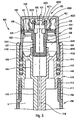
figure 1 est une vue en coupe transversale verticale à travers un organe de distribution selon un premier mode de réalisation à l'état de repos et associé à un réservoir de produit fluide représenté seulement partiellement, - la
figure 2 est une vue similaire à lafigure 1 en position actionnée, - les
figures 3a et 3b sont des vues schématiques de la surface interne de la paroi de distribution formée avec un système de tourbillonnement selon l'invention, respectivement en position de repos et actionnée, - les
figures 4a et 4b sont des vues en coupe transversale verticale à travers des organes de distribution selon deux variantes de réalisation, - la
figure 5 est une vue en coupe transversale verticale similaire à celle desfigures 1 et2 pour un autre mode de réalisation de l'invention en position de repos, - la
figure 6 est une vue similaire à lafigure 5 en position actionnée, et - la
figure 7 est une vue en coupe transversale verticale à travers un organe de distribution selon encore un autre mode de réalisation de l'invention en position de repos. - L'organe de distribution du premier mode de réalisation des
figures 1 et2 est représenté associé à un récipient 150 comprenant un corps 151 définissant intérieurement un réservoir de produit fluide 5. Le corps 151 est pourvu à son extrémité supérieure d'une ouverture sous la forme d'un col 153, qui sert à la fixation de l'organe de distribution de l'invention. - L'organe de distribution comprend trois éléments constitutifs, à savoir un corps 110, un poussoir 120 et un organe de piston 130. L'organe de distribution comprend en outre des moyens de ressort sous la forme d'un ressort à boudin 140. Le corps, le poussoir et l'organe de piston sont de préférence réalisés par moulage de matière plastique. L'organe de distribution a la conception d'une pompe comprenant une chambre de pompe 1.
- Le corps 110 comprend une bague de fixation 111 qui coopère avec le col 153 pour la fixation de l'organe sur le récipient 150. La bague 111 est en prise avec l'extérieur du col 153. D'autre part, le corps forme une lèvre autojointante 112 en prise étanche avec la paroi interne du col 153. Le corps 111 forme également une douille de guidage 114 qui peut s'étendre avantageusement dans le prolongement de la bague 111. L'extrémité supérieure de la douille de guidage 114 est formée avec un rabat rentrant 1141. Le corps 110 forme également une couronne 113 qui s'étend de manière concentrique à l'intérieur de la douille de guidage 114. Ainsi, un annulaire est formé entre la douille 114 et la couronne 113. La couronne 113 forme à son extrémité supérieure un épaulement 1131 qui va servir de surface d'appui pour le ressort 140. La couronne 113 se prolonge vers le haut en formant un fût principal 117 qui définit intérieurement une surface de coulissement étanche, dont la fonction sera donnée ci-après. Le corps forme également un tube plongeur 115 qui s'étend à l'intérieur du récipient 150. Le tube plongeur 115 se prolonge à son extrémité supérieure par un manchon d'entrée 116 qui forme un profil ou siège de clapet d'entrée 1161. Le tube plongeur 115 ainsi que le manchon 116 sont traversés par un conduit d'entrée 118. Le manchon d'entrée 116 s'étend de manière concentrique à l'intérieur du fût principal 117, de sorte qu'un espace annulaire est formé entre eux.
- Le corps 110 présente une symétrie axiale de révolution autour d'un axe X qui s'étend de manière longitudinale au centre axial du conduit d'entrée 118.
- Il s'agit là d'une conception particulière pour un corps particulier d'un organe de distribution selon une première forme de réalisation de l'invention. Bien entendu, le corps peut présenter d'autres caractéristiques que celles qui viennent d'être décrites, sans pour autant sortir du cadre de l'invention.
- Le poussoir 120 forme une tête de distribution de l'organe de distribution. Le poussoir 120 comprend une paroi d'appui 121 et une jupe périphérique 122 qui s'étend vers le bas à partir de la périphérie externe de la paroi d'appui. Ainsi, le poussoir 120 présente une forme générale de godet renversé dont la paroi d'appui forme le fond et la jupe la paroi latérale cylindrique. Toutefois, la jupe n'est pas forcément de forme cylindrique. Elle peut présenter des sections tronconiques ou arrondies.
- La paroi d'appui 121 comprend une surface externe d'appui 1211 sur laquelle on peut appuyer à l'aide d'un ou de plusieurs doigt(s). D'autre part, la paroi d'appui 121 comprend une surface interne 1212 qui forme avantageusement un plot de butée 1213.
- La jupe 122 comprend une paroi supérieure de distribution 123 et une paroi inférieure de guidage 124. La paroi de distribution 123 est raccordée à son extrémité supérieure à la périphérie externe de la paroi d'appui 121. La paroi de distribution 123 comprend une surface externe 1221 et une surface interne 1232. Cette surface interne 1232 est de préférence cylindrique circulaire et définit un fût de coulissement comme on le verra ci-après. D'autre part, la paroi de distribution 123 est formée avec un orifice de distribution traversant 125 qui s'étend de la surface interne jusqu'à la surface externe. L'orifice de distribution 125 peut déboucher au niveau de la surface externe dans une coupelle de diffusion 1251.
- Selon une caractéristique intéressante de l'invention, la paroi interne 1232 de la paroi de distribution 123 est formée avec un système de tourbillonnement 126 qui permet d'entraîner du produit fluide en rotation sous la forme d'un tourbillonnement dont l'oeil est centré sur l'orifice de distribution. Ainsi, la paroi de distribution 123, qui est avantageusement réalisée de manière monobloc avec la paroi d'appui 121 et la paroi de guidage 124, est traversée par un orifice de distribution et comprend une surface interne formée avec un système de tourbillonnement.
- La paroi de guidage 124 comprend un cordon de butée 141 sur sa surface externe destiné à coopérer avec le rabat rentrant 1141 de la douille de guidage 114. La paroi de guidage 124 est disposée dans l'annulaire formé entre la douille de guidage 114 et la couronne 113. Le cordon de butée 1241 permet de solidariser le poussoir au corps, qui ne peut ainsi que se déplacer axialement sur une course maximale déterminée par la distance séparant l'extrémité inférieure de la paroi de guidage 124 et le fond de l'annulaire formé entre la douille 114 et la couronne 113.
- L'organe de piston 130 comprend, dans ce mode de réalisation, un piston principal 136 engagé à coulissement étanche dans le fût principal 117 et un piston différentiel formé par deux lèvres 132 et 133 en contact de coulissement étanche dans le fût formé par la surface interne 1232 de la paroi de distnbution 123. L'organe de piston 130 est avantageusement réalisé de manière monobloc. Les lèvres 132 et 133 s'étendent l'une au-dessus de l'autre avec un écartement supérieur à l'étendue axiale du système de tourbillonnement 126. Dans la position de repos représentée sur la
figure 1 , la lèvre supérieure 132 est en contact de la surface interne 1232 au-dessus du système de tourbillonnement 126, alors que la lèvre inférieure 133 vient en contact de la surface interne 1232 en dessous du système de tourbillonnement 126. Ainsi, le système de tourbillonnement ne peut pas communiquer avec l'intérieur du poussoir hormis au niveau de l'espace formé entre les deux lèvres 132 et 133. Il s'agit de la position de repos dans laquelle l'organe de piston 130 est sollicité contre la paroi d'appui 121 par le ressort 140, qui prend appui d'une part sur l'épaulement 1131 et d'autre part sous un plateau 131 formé par l'organe de piston 130. D'ailleurs, les deux lèvres 132 et 133 sont formées sur la périphérie extérieure du plateau 131. En son centre, le plateau vient en butée contre le plot de butée 1213 formé au niveau de la surface interne 1212 de la paroi d'appui 121. On peut considérer que le piston différentiel est formé par le plateau 131 formant les deux lèvres 132 et 133. L'organe de piston 130 forme également une tige centrale axiale 137 qui s'étend à partir du plateau 131 en éloignement de la paroi d'appui 121. Cette tige axiale 137 est partiellement engagée à l'intérieur du manchon d'entrée 116 formé par le corps 110. La tige 137 forme un profil de clapet 138 destiné à coopérer avec le profil correspondant 1161 formé par le manchon 116. En d'autres termes, la tige 137 en coopération avec le manchon 116 forme un clapet d'entrée pour une chambre de pompe 1, comme on le verra ci-après. D'autre part, l'organe de piston 130 forme une couronne de piston 135 à l'extrémité inférieure de laquelle est formé le piston principal 136. La couronne de piston 135 s'étend de manière concentrique autour de la tige axiale 137, de manière à définir entre elles un conduit annulaire qui s'étend à travers le plateau 131 à travers des trous de passage de produit fluide 134. - Le corps 110, le poussoir 120 et l'organe de piston 130 forment ensemble une chambre de pompe 1 qui s'étend de manière continue entre le fût principal 117 et le manchon 116, entre la couronne de piston 135 et la tige axiale 137, dans les trous de passage 134, et entre le plateau 131 et la surface interne 1212 de la paroi d'appui 121. Ainsi, la surface supérieure du plateau 131 et la surface interne 1212 forment des éléments de paroi de la chambre de pompe 1. Dans la position de repos représentée sur la
figure 1 , le ressort 140 pousse l'organe de piston 130 en butée contre la paroi d'appui 121. Le clapet d'entrée formé en coopération entre la tige axiale 137 et le manchon 116 est ouvert. Les deux lèves 132 et 133 du piston différentiel sont en contact du fût formé par la surface interne 1232 de la paroi d'actionnement 123 comme représenté en traits pointillés sur lafigure 3a . - En exerçant une force sur la surface externe d'appui 1211 de la paroi d'appui 121, le poussoir se déplace axialement par rapport au corps 110. Etant donné que l'organe de piston est en butée contre la paroi d'appui, l'organe de piston est poussé par le poussoir. Dans un premier temps, le déplacement du poussoir a pour effet de fermer le clapet d'entrée : la tige axiale 137 s'engage plus profondément dans le manchon 116 jusqu'à ce qu'un contact étanche coulissant soit créé entre le manchon ou la tige. Ainsi, la chambre de pompe 1 est isolée du réservoir 5. A partir de ce moment, le produit dans la chambre de pompe 1 va être mis sous pression. Du fait que le produit fluide est incompressible, le volume utile total de la chambre de pompe reste obligatoirement constant. Mais-comme le piston principal 136 s'enfonce dans le fût 117 diminuant ainsi le volume de la partie basse de la chambre, un nouveau volume doit être crée. Ceci est possible du fait que le piton différentiel se déplace en éloignement de la paroi d'appui 121. Ceci a pour effet de faire coulisser les lèvres 132 et 133 à l'intérieur de la paroi de distribution 123. Les lèvres se déplacent ainsi jusqu'à ce que la lèvre supérieure 132 arrive au niveau du système de tourbillonnement 126. Ceci est représenté sur la
figure 2 . A ce moment, le produit fluide sous pression dans la chambre de pompe trouve un passage de sortie à travers le système de tourbillonnement et l'orifice de distribution. La position de la lèvre supérieure 132 est représentée en traits pointillés sur lafigure 3b . Le passage reste ainsi ouvert tant que la pression à l'intérieur de la chambre peut surmonter la force du ressort 140. Dès que la pression diminue en dessous d'un certain seuil à l'intérieur de la chambre, le ressort 140 repousse le piston différentiel vers la position de repos représentée sur lafigure 3a . Le système de tourbillonnement et l'orifice de distribution sont alors à nouveau isolés de la chambre de pompe. - On peut noter que la lèvre supérieure 132 est directement contact du produit fluide, alors que la lèvre inférieure n'est pas directement en contact du produit fluide. Ainsi, la lèvre supérieure coulisse dans la partie supérieure du fût défini entre la paroi d'appui et le système de tourbillonnement. Or, cette partie du fût a une meilleure qualité de surface que la partie inférieure qui s'étend en dessous du système de tourbillonnement, qui peut être endommagée par le retrait de la broche de moulage.
- Les
figures 3a et 3b représentent un mode de réalisation particulier non limitatif pour le système de tourbillonnement formé dans la paroi de distribution de l'organe de distribution de l'invention. Ce système de tourbillonnement comprend au moins un canal tangentiel de tourbillonnement 1262. Sur les figures, il y a trois canaux tangentiels disposés de manière équiangulaire. D'autre part, le système de tourbillonnement comprend également une chambre de tourbillonnement centrale 1261 qui est centrée avec précision par rapport à l'orifice de distribution 125. Optionnellement, le système de tourbillonnement peut comprendre un anneau périphérique d'alimentation 163 qui permet d'alimenter tous les canaux de tourbillonnement 1262. Si nécessaire, le système de tourbillonnement peut être réduit à un seul canal de tourbillonnement associé à la chambre de tourbillonnement centrale. - Une caractéristique intéressante de l'invention réside dans le fait que l'organe de piston 140 est sollicité contre la paroi d'appui 121 et se déplace sous l'effet de l'augmentation de pression à l'intérieur de la chambre de pompe en éloignement de cette paroi d'appui. Ceci est notamment rendu possible grâce aux trous de passage de produit fluide 134 qui traversent le plateau 131 formant le piston différentiel. On peut aussi dire que la paroi d'appui définit un élément de paroi de la chambre de pompe.
- Un tel déplacement du piston différentiel en éloignement de la paroi d'appui, en association avec un système de tourbillonnement formé dans la paroi de distribution, est avantageux sur le plan du démoulage étant donné que la lèvre supérieure 132 coulisse de manière étanche sur la partie supérieure du fût de coulissement qui ne pas être détériorée par le retrait de la broche de moulage formant l'empreinte négative qui a servi à mouler le système de tourbillonnement.
- On peut également noter que la position de repos est atteinte lorsque le cordon de butée 1241 formé par la paroi de guidage 124 est en appui sous le rabat rentrant 1141.
- D'autre part, le guidage axial du poussoir est assuré, d'une part par le guidage axial de la paroi de guidage 124 entre la douille 114 et la couronne 113, et d'autre part par l'engagement de la couronne de piston 135 et la tige axiale 137 respectivement dans le fût principal 117 et le manchon d'entrée 116.
- Les
figures 4a et 4b représentent deux variantes de réalisation du mode de réalisation desfigures 1 et2 . - Dans la variante de la
figure 4a , le ressort de rappel et de précompression est formé de manière monobloc par le corps 210 et porte la référence numérique 2171. Le ressort s'étend dans le prolongement du fût principal 217 et vient en appui sous le plateau 231 qui forme le piston différentiel avec ses deux lèvres 232 et 233. Le ressort 2171 s'étend ainsi de manière concentrique autour de la couronne 230 qui forme le piston principal 236. Hormis le ressort de rappel, l'organe de distribution 200 de lafigure 4a peut être identique à celui desfigures 1 et2 . - Dans le mode de réalisation 4b, l'organe de distribution 300 comprend un ressort de rappel 3311 qui est réalisé de manière monobloc par l'organe de piston 330. Plus précisément, le ressort 3311 s'étend à partir de la face inférieure du plateau 331. Il vient en appui à son extrémité inférieure sur l'épaulement 3331 formé par le corps 310. Hormis la forme particulière du ressort, l'organe de distribution 300 peut être identique à celui des
figures 1 et2 . - Dans ces variantes de réalisation des
figures 4a et 4b , l'organe de distribution comprend uniquement trois éléments constitutifs, à savoir un corps, un poussoir et un organe de piston, le ressort de rappel et de précompression étant intégré soit au corps soit à l'organe de piston. - Le mode de réalisation de l'organe de distribution selon l'invention représenté sur les
figures 5 et6 est représenté en association avec un récipient 450 définissant une ouverture sous la forme d'un col 453 qui présente avantageusement au niveau de sa surface externe un profil de fixation. Le récipient 450 définit intérieurement un réservoir de produit fluide 5. - L'organe de distribution référencé dans son ensemble par la référence numérique 400 comprend trois éléments constitutifs, à savoir un corps 410, un poussoir 420 et un organe de piston 430. Ces trois pièces peuvent être réalisées par injection/moulage de matière plastique.
- Le corps 410 comprend une bague de fixation 411 coopérant avec le col 453 du récipient 450. Plus précisément, la bague 411 vient en prise autour du col 453. Le corps 410 peut également comprendre une lèvre autojointante 412 en contact d'étanchéité avec la paroi interne du col 453. Une douille de guidage 414 peut s'étendre dans le prolongement de la bague de fixation 411. La bague 414 comprend au niveau de son extrémité supérieure un rabat rentrant 4141 dont la fonction sera donnée ci-après. Le corps 410 comprend également une couronne 413 qui s'étend de manière concentrique à l'intérieur de la douille de guidage 414. Ainsi, il est créé un espace annulaire entre la douille 414 et la couronne 413. L'extrémité supérieure de la couronne 413 forme un piston principal 4133 sous la forme d'une lèvre d'étanchéité. Le corps 410 comprend également un manchon d'entrée 416 qui s'étend de manière concentrique à l'intérieur de la couronne 413. L'extrémité supérieure du manchon 416 forme un profil ou siège de clapet 4161. D'autre part, le corps 410 forme de manière monobloc un tube plongeur 415 qui s'étend dans le récipient 450. Le tube plongeur définit intérieurement un conduit d'entrée 418 qui s'étend jusque dans le manchon d'entrée 416.
- Le poussoir 420 comprend une paroi d'appui 421 ainsi qu'une jupe périphérique 422. La jupe 422 se raccorde à la paroi d'appui 420 au niveau de sa périphérie extérieure. La paroi d'appui 421 comprend une surface externe d'appui 4211 ainsi qu'une surface interne 4212. La paroi d'appui 421 et la jupe 422 présentent une forme générale de godet retourné avec le fond du godet formé par la paroi d'appui 421 et la paroi latérale cylindrique formée par la jupe 422. La paroi d'appui 421 comprend des moyens de ressort sous la forme de pattes ou de lames élastiquement déformables 427 qui s'étendent à partir de la surface interne 4212. D'autre part, la paroi d'appui 421 comprend un organe de retenue 428 qui s'étend également à partir de la surface interne 4212. L'organe de retenue 428 comprend au moins un profil de retenue 4281 présentant une arête de retenue orientée vers la surface interne 4212. En pratique, l'organe de retenue peut comprendre plusieurs profils de retenue formés à l'extérieur d'une tourette qui s'étend vers le bas à partir de la paroi d'appui 421.
- La jupe 422 comprend une paroi de distribution 423 ainsi qu'une paroi de guidage 424.
- La paroi de distribution 423 est reliée par son extrémité supérieure à la périphérie externe de la paroi d'appui 421. La paroi de guidage 424 se raccorde par son extrémité supérieure à l'extrémité inférieure de la paroi de distribution 423. La paroi de distribution 423 comprend une surface externe ainsi qu'une surface interne 4232. La surface interne est au moins partiellement cylindrique de manière à constituer un fût de coulissement étanche. La paroi interne 4232 est avantageusement formée avec un système de tourbillonnement 426 qui forme un réseau évidé dans la surface cylindrique 4232. Ce système de tourbillonnement peut comprendre un ou plusieurs canaux de tourbillonnement ainsi qu'une chambre de tourbillonnement. D'autre part, la paroi de distribution 423 est formée avec un orifice de distribution qui traverse la paroi de manière à s'étendre de la surface interne jusqu'à la surface externe. L'orifice de distribution 425 est centré par rapport au système de tourbillonnement 426. Le système de tourbillonnement peut être identique à celui représenté sur les
figures 3a et 3b . - La paroi de guidage 424 est engagée dans l'espace annulaire formé entre la douille de guidage 414 et la couronne 413. La paroi de guidage forme un épaulement 4241 destiné à venir en butée sous le rabat rentrant 4141 de la douille 414. Avantageusement, la surface interne 4242 de la paroi de guidage 424 forme un fût principal dans lequel le piston principal 4133 est déplaçable en contact étanche. La paroi de guidage 424 est sollicitée par un ressort 440 qui pousse l'épaulement 4241 contre le rabat rentrant 4141. Le ressort 440 peut avantageusement être réalisé de manière monobloc par le poussoir dans le prolongement de la paroi de guidage 424. Ainsi, le piston principal 4133 peut coulisser à l'intérieur du poussoir, ou plus précisément à l'intérieur de la paroi de guidage 424 qui forme intérieurement le fût principal 4242.
- L'organe de piston 430 forme ici un piston différentiel associé à un organe mobile de clapet d'entrée. L'organe de piston 430 comprend un plateau 431 qui forme au niveau de sa périphérie externe deux lèvres d'étanchéité 432 et 433. Le plateau 431 et ses deux lèvres forment ensemble le piston différentiel. En position de repos représentée sur la
figure 5 , la lèvre supérieure 432 est positionnée au-dessus du système de tourbillonnement, alors que la lèvre inférieure 433 est positionnée en dessous du système de tourbillonnement. Ainsi, le système de tourbillonnement ne peut pas communiquer avec l'intérieur du poussoir. D'autre part, le plateau 431 forme un logement annulaire 4311 destiné à recevoir les extrémités libres des pattes élastiquement déformables 427 formées par la paroi d'appui 421. En outre, l'organe de piston 430 forme un élément d'accrochage 439 qui s'étend à partir du plateau 431 en direction de la paroi d'appui 421. Cet élément d'accrochage 439 comprend des têtes d'accrochage 4392 situées à l'extrémité de pattes 4391. Les têtes d'accrochage 4392 sont en prise entre la paroi interne 4212 et les profils de retenue 4281 formés par l'organe de retenue 428. Ainsi, les têtes peuvent se déplacer sur une course limitée entre les profils de retenue et la surface interne de la paroi d'appui. Cependant, les pattes élastiquement déformables 427 sollicitent l'organe de piston 430 en éloignement de la paroi d'appui 421, de sorte que les têtes d'accrochage 4392 sont poussées en prise avec les profils de retenue 4281. Les têtes d'accrochage 4392 peuvent venir en contact contre la surface interne 4212 en fléchissant les pattes élastiquement déformables 427. Il existe ainsi des moyens de limitation de course constitués par la coopération de l'organe de retenue avec l'élément d'accrochage. - L'organe de piston 430 est ainsi prisonnier à l'intérieur du poussoir tout en étant capable de se déplacer axialement sur une course limitée. Les pattes élastiquement déformables 427 sollicitent cependant l'organe de piston en position de repos, dans laquelle les têtes d'accrochage sont en prises avec les profils de retenue. En outre, les lèvres d'étanchéité 432 et 433 sont positionnées de part et d'autre du système de tourbillonnement de manière à l'isoler. Ceci correspond à la position de repos représentée sur la
figure 5 . - D'autre part, l'organe de piston 430 forme également une tige centrale axiale 437 qui présente au niveau de son extrémité inférieure un profil de clapet d'entrée 438 qui coopère avec le profil correspondant 4161 du manchon 416 pour former ensemble le clapet d'entrée. Dans la position de repos, le clapet d'entrée est ouvert.
- Ainsi, une chambre de pompe 1 est créée entre le corps le poussoir et l'organe de piston. La chambre de pompe 1 est isolée de l'extérieur par la lèvre inférieure 433 mais communique cependant avec le réservoir à travers le clapet d'entrée ouvert.
- A partir de la position de repos de la
figure 5 , on peut exercer une pression sur la surface d'appui externe 4211 de la paroi d'appui 421. Ceci a pour effet de déplacer le poussoir et l'organe de piston par rapport au corps. Dans un premier temps, le clapet d'entrée va être fermé du fait que la tige axiale 437 pénètre plus profondément dans le manchon 416 de manière à créer un contact étanche coulissant. A partir de ce moment, la chambre de pompe 1 est isolée de l'extérieur. Le produit fluide dans la chambre de pompe est alors soumis à une augmentation de pression, ce qui a pour effet de déplacer l'organe de piston 430 en direction de la paroi d'appui 421, à l'encontre de la force de ressort exercée par les pattes élastiques 427. Ainsi, la lèvre inférieure 433 va se déplacer vers le haut jusqu'à arriver au niveau du système de tourbillonnement 426. A partir de ce moment, le produit fluide trouve un passage de sortie à travers le système de tourbillonnement et l'orifice de distribution. Cette position d'actionnement est représentée sur lafigure 6 . Pour atteindre cette position, il faut que la pression à l'intérieur de la chambre de pompe soit supérieure à la raideur des pattes élastiquement déformables 427, qui jouent par conséquence un rôle de ressort de précompression. L'organe de piston 430 peut se déplacer en direction de la paroi d'appui 421 jusqu'à ce que les têtes d'accrochage 4392 arrivent en butée contre la surface interne 4212. Dans cette position, qui est celle de lafigure 6 , la lèvre d'étanchéité inférieure 433 du piston différentiel est positionnée au niveau du système de tourbillonnement. Dès que la pression à l'intérieur de la chambre diminue à nouveau, l'organe de piston 430 peut s'éloigner à nouveau de la paroi d'appui 421 sous l'action des pattes élastiques 427. L'organe de piston 430 revient finalement dans sa position de repos représentée sur lafigure 5 . - L'organe de piston 430 est prisonnier du poussoir tout en lui laissant une liberté de déplacement axial limitée. Il faut aussi noter que le ressort de précompression est formé de manière monobloc par le poussoir. D'autre part, la captivité de l'organe de piston et son déplacement limité sont entièrement assurés par le poussoir et l'organe de piston; sans pièce supplémentaire.
- Dans le mode de réalisation représenté sur la
figure 7 , l'organe de distribution comprend un corps 510, un poussoir 520, un organe de piston 530 et une bague de fixation 570. L'organe de distribution est monté sur un récipient 550 formant intérieurement un réservoir 5 et comprenant une ouverture sous la forme d'un col 553 dépourvu de profils de fixation. - Une différence avec les modes de réalisation des figures précédentes réside dans le fait que le corps ne réalise plus la fixation sur l'ouverture du réservoir. Au contraire, dans ce mode de réalisation, le corps 510 est engagé dans une bague de fixation 570 qui réalise la connexion étanche sur l'ouverture de réservoir. A ce titre, la bague de fixation 570 comprend une lèvre autojointante 572 engagée en force de manière étanche à l'intérieur de l'ouverture 553 du récipient 550. La bague 570 comprend une collerette d'appui 571 en appui sur l'extrémité supérieure de l'ouverture 553. En outre, le corps forme une bride rentrante 575 qui délimite une ouverture de passage pour le tube plongeur 515 du corps 510. La bague 570 comprend également une couronne 573 qui définit intérieurement un logement pour le corps 510. La couronne 573 se prolonge à son extrémité supérieure par une douille de guidage 574. D'autre part, la bague 570 forme également un ressort de rappel et de précompression 576 qui s'étend de manière monobloc à partir de la couronne 573 de manière concentrique à l'intérieur de la douille de guidage 574. La douille de guidage 574 forme également sur sa surface extérieure un profil de butée 5741 qui coopère avec le poussoir 520.
- Le corps 510 est engagé à l'intérieur de la bague 570, ou plus précisément à l'intérieur de la couronne 573 en venant en butée sur la bride rentrante 575. Tout comme dans les autres modes de réalisation précédents, le corps 510 forme un fût de coulissement 517, un tube plongeur 515, un manchon d'entrée 516.
- L'avantage de réaliser le corps et la bague en deux pièces distinctes séparées réside dans le fait qu'il est possible d'utiliser des matériaux différents pour le corps et la bague. Ceci se justifie particulièrement en raison du fait que la bague est souvent un élément décoratif alors que le corps est un élément fonctionnel. Si l'on veut par exemple réaliser la bague en une matière plastique colorée, cela ne doit pas être le cas du tube plongeur qui est visible très souvent à travers le récipient. D'autre part, il est plus facile de réaliser le ressort 576 avec la bague 570 lorsque le corps est réalisé séparément.
- L'organe de piston 530 peut être strictement identique à celui des modes de réalisation précédents des
figures 1 à 4 . On peut cependant remarquer que l'organe de piston 530 est réalisé avec une nervure de guidage 5351 destinée à coulisser de manière non étanche autour du manchon 516. - Tout comme dans les modes de réalisation des
figures 1 à 4 , l'organe de piston forme un piston différentiel ainsi qu'un piston principal. Le piston différentiel coulisse dans le poussoir 520 alors que le piston principal coulisse dans le manchon 517. L'organe de piston 530 est destiné à se déplacer en éloignement de la paroi d'appui du poussoir lorsque la pression augmente. Ceci a pour effet de démasquer un orifice de pulvérisation 525 avantageusement équipé d'un système de tourbillonnement 526 qui est réalisé dans la surface interne de la paroi de guidage 523. On peut également remarquer que l'extrémité inférieure du poussoir vient en prise de butée contre le profil de butée 5741. Le diamètre externe du poussoir est sensiblement identique à celui du récipient. De cette manière, la bague de fixation 570 n'est que très peu visible.
Claims (11)
- Organe de distribution de produit fluide (100 ; 200 ; 300 ; 400) comprenant une paroi de distribution (123 ; 223 ; 323 ; 423) définissant une surface externe et une surface interne, ladite paroi étant traversée par un orifice de distribution (125 ; 225 ; 325 ; 425) reliant la surface interne à la surface externe, la surface interne formant un fût de coulissement étanche pour un piston (131, 132, 133 ; 231, 232, 233 ; 331, 332, 333 ; 431, 432, 433) apte à se déplacer en contact étanche dans ledit fût pour démasquer sélectivement l'orifice de distribution, le piston étant un piston différentiel qui se déplace en réponse à une variation de pression dans une chambre de produit fluide (1), ledit piston différentiel comprenant au moins une lèvre d'étanchéité (132, 133 ; 232, 233 ; 332, 333 ; 432, 433) en contact de coulissement étanche avec le fût de coulissement, ledit piston formant un élément de paroi de la chambre de produit fluide (1) dans laquelle du produit fluide est sélectivement mis sous pression, la surface interne, au niveau du fût de coulissement, formant un système de tourbillonnement de produit fluide (126 ; 226 ; 326 ; 426) immédiatement en amont de l'orifice de distribution,
la paroi de distribution étant formée par une jupe sensiblement cylindrique (122 ; 222 ; 322 ; 422) comprenant en outre une paroi de guidage (124 ; 224 ; 324 ; 424) définissant une surface interne dont le diamètre interne est supérieur à celui du fût de coulissement,
caractérisé en ce que le piston différentiel est solidaire d'un piston principal (136 ; 236 ; 336) en contact de coulissement étanche dans un fût principal. - Organe de distribution de produit fluide selon la revendication 1, dans lequel le fût de coulissement, l'orifice de distribution et le système de tourbillonnement sont formés de manière monobloc par la paroi de distribution.
- Organe de distribution de produit fluide selon l'une quelconque des revendications précédentes, dans lequel la paroi de distribution est formée par un poussoir (120 ; 220 ; 320 ; 420) comprenant en outre une paroi d'appui (121 ; 221 ; 321 ; 421) qui se prolonge sur sa périphérie externe par la paroi de distribution.
- Organe de distribution de produit fluide selon la revendication 3, dans lequel le piston est sollicité élastiquement contre la paroi d'appui et est déplaçable en éloignement de cette paroi d'appui pour démasquer l'orifice de distribution.
- Organe de distribution de produit fluide selon la revendication 2, dans lequel le piston est sollicité élastiquement en éloignement de la paroi de guidage et est déplaçable vers cette paroi de guidage.
- Organe de distribution de produit fluide selon la revendication 3, dans lequel le piston est sollicité élastiquement en éloignement de la paroi d'appui et est déplaçable vers cette paroi d'appui.
- Organe de distribution de produit fluide selon la revendication 4 ou 5, dans lequel la paroi d'appui comprend une surface interne (1212 ; 2212 ; 3212) qui forme un élément de paroi de la chambre.
- Organe de distribution de produit fluide selon l'une quelconque des revendications précédentes, comprenant un corps (110 ; 210 ; 310) destiné à être associé à un réservoir de produit fluide, ledit corps formant un fût principal dans lequel coulisse un piston principal.
- Organe de distribution de produit fluide selon l'une quelconque des revendications précédentes, dans lequel la paroi de distribution est formée par une jupe sensiblement cylindrique (422) qui forme en outre une paroi de guidage (424) définissant une surface interne formant un fût principal pour un piston principal.
- Organe de distribution de produit fluide selon l'une quelconque des revendications précédentes, dans lequel le système de tourbillonnement comprend au moins un canal de tourbillonnement (1262) et une chambre, (1261) de tourbillonnement centrée sur l'orifice de distribution et optionnellement une couronne d'alimentation périphérique (1263).
- Organe de distribution de produit fluide selon l'une quelconque des revendications précédentes, dans lequel le système de tourbillonnement forme un réseau évidé par rapport à la surface interne sensiblement cylindrique de la paroi de distribution.
Applications Claiming Priority (2)
| Application Number | Priority Date | Filing Date | Title |
|---|---|---|---|
| FR0315193A FR2864046B1 (fr) | 2003-12-22 | 2003-12-22 | Organe de distribution de produit fluide. |
| PCT/FR2004/050737 WO2005063402A1 (fr) | 2003-12-22 | 2004-12-20 | Organe de distribution de produit fluide |
Publications (2)
| Publication Number | Publication Date |
|---|---|
| EP1703986A1 EP1703986A1 (fr) | 2006-09-27 |
| EP1703986B1 true EP1703986B1 (fr) | 2010-04-14 |
Family
ID=34630468
Family Applications (1)
| Application Number | Title | Priority Date | Filing Date |
|---|---|---|---|
| EP04817624A Active EP1703986B1 (fr) | 2003-12-22 | 2004-12-20 | Organe de distribution de produit fluide |
Country Status (8)
| Country | Link |
|---|---|
| EP (1) | EP1703986B1 (fr) |
| JP (1) | JP2007515288A (fr) |
| CN (1) | CN100509173C (fr) |
| BR (1) | BRPI0417954A (fr) |
| DE (1) | DE602004026636D1 (fr) |
| ES (1) | ES2342470T3 (fr) |
| FR (1) | FR2864046B1 (fr) |
| WO (1) | WO2005063402A1 (fr) |
Families Citing this family (3)
| Publication number | Priority date | Publication date | Assignee | Title |
|---|---|---|---|---|
| GB0413164D0 (en) * | 2004-06-12 | 2004-07-14 | Ten Cate Plasticum Uk Ltd | Dispensing apparatus |
| FR2914286B1 (fr) * | 2007-03-29 | 2011-09-30 | Valois Sas | Distributeur de produit fluide |
| KR101747920B1 (ko) | 2015-08-24 | 2017-06-15 | (주)연우 | 식별수단이 구비된 화장품 용기 |
Family Cites Families (3)
| Publication number | Priority date | Publication date | Assignee | Title |
|---|---|---|---|---|
| US4050613A (en) * | 1976-08-31 | 1977-09-27 | Corsette Douglas Frank | Manual actuated dispensing pump |
| AU534828B2 (en) * | 1979-05-16 | 1984-02-16 | Yoshino Kogosho Co. Ltd. | Atomizer |
| FR2742812B1 (fr) | 1995-12-22 | 1998-02-20 | Valois | Pompe a precompression formee dans le poussoir |
-
2003
- 2003-12-22 FR FR0315193A patent/FR2864046B1/fr not_active Expired - Fee Related
-
2004
- 2004-12-20 ES ES04817624T patent/ES2342470T3/es active Active
- 2004-12-20 BR BRPI0417954-4A patent/BRPI0417954A/pt not_active Application Discontinuation
- 2004-12-20 EP EP04817624A patent/EP1703986B1/fr active Active
- 2004-12-20 WO PCT/FR2004/050737 patent/WO2005063402A1/fr active Application Filing
- 2004-12-20 DE DE602004026636T patent/DE602004026636D1/de active Active
- 2004-12-20 CN CNB2004800416420A patent/CN100509173C/zh active Active
- 2004-12-20 JP JP2006546282A patent/JP2007515288A/ja not_active Withdrawn
Also Published As
| Publication number | Publication date |
|---|---|
| ES2342470T3 (es) | 2010-07-07 |
| FR2864046A1 (fr) | 2005-06-24 |
| CN1913971A (zh) | 2007-02-14 |
| BRPI0417954A (pt) | 2007-04-17 |
| WO2005063402A1 (fr) | 2005-07-14 |
| CN100509173C (zh) | 2009-07-08 |
| DE602004026636D1 (de) | 2010-05-27 |
| FR2864046B1 (fr) | 2006-12-01 |
| EP1703986A1 (fr) | 2006-09-27 |
| JP2007515288A (ja) | 2007-06-14 |
Similar Documents
| Publication | Publication Date | Title |
|---|---|---|
| EP0623060B1 (fr) | Pompe a precompression perfectionnee | |
| EP1701799B1 (fr) | Organe de distribution de produit fluide et distributeur comprenant un tel organe | |
| EP1344571B1 (fr) | Ensemble pour le conditionnement et la distribution d'un produit, notamment sous forme d'un échantillon | |
| FR2854131A1 (fr) | Procede de remplissage de reservoir de produit fluide, ensemble de remplissage de produit fluide et source de remplissage | |
| WO2008003894A2 (fr) | Distributeur de produit fluide | |
| FR2852302A1 (fr) | Organe de distribution de produit fluide et distributeur de produit fluide comprenant un tel organe | |
| WO2000063095A1 (fr) | Organe de fixation pour distributeur de produit fluide et distributeur comportant un tel organe | |
| EP1472007B1 (fr) | Distributeur de produit liquide a pompe | |
| EP1706212B1 (fr) | Pompe de distribution de produit fluide | |
| EP1722896B1 (fr) | Organe de distribution de produit fluide. | |
| FR2906232A1 (fr) | Dispositif de distribution de produit fluide. | |
| EP2069077B1 (fr) | Dispositif de distribution de produit fluide | |
| EP1703986B1 (fr) | Organe de distribution de produit fluide | |
| FR2864045A1 (fr) | Organe de distribution de produit fluide. | |
| EP2178649B1 (fr) | Organe de distribution de produit fluide | |
| EP3755645B1 (fr) | Distributeur de produit fluide | |
| EP1703985B1 (fr) | Distributeur de produit fluide | |
| FR2855504A1 (fr) | Distributeur de produit fluide | |
| EP3814019A1 (fr) | Distributeur de produit fluide |
Legal Events
| Date | Code | Title | Description |
|---|---|---|---|
| PUAI | Public reference made under article 153(3) epc to a published international application that has entered the european phase |
Free format text: ORIGINAL CODE: 0009012 |
|
| 17P | Request for examination filed |
Effective date: 20060719 |
|
| AK | Designated contracting states |
Kind code of ref document: A1 Designated state(s): DE ES FR GB IT |
|
| DAX | Request for extension of the european patent (deleted) | ||
| RBV | Designated contracting states (corrected) |
Designated state(s): DE ES FR GB IT |
|
| 17Q | First examination report despatched |
Effective date: 20070531 |
|
| GRAP | Despatch of communication of intention to grant a patent |
Free format text: ORIGINAL CODE: EPIDOSNIGR1 |
|
| GRAS | Grant fee paid |
Free format text: ORIGINAL CODE: EPIDOSNIGR3 |
|
| GRAA | (expected) grant |
Free format text: ORIGINAL CODE: 0009210 |
|
| AK | Designated contracting states |
Kind code of ref document: B1 Designated state(s): DE ES FR GB IT |
|
| REG | Reference to a national code |
Ref country code: GB Ref legal event code: FG4D Free format text: NOT ENGLISH |
|
| REF | Corresponds to: |
Ref document number: 602004026636 Country of ref document: DE Date of ref document: 20100527 Kind code of ref document: P |
|
| REG | Reference to a national code |
Ref country code: ES Ref legal event code: FG2A Ref document number: 2342470 Country of ref document: ES Kind code of ref document: T3 |
|
| PLBE | No opposition filed within time limit |
Free format text: ORIGINAL CODE: 0009261 |
|
| STAA | Information on the status of an ep patent application or granted ep patent |
Free format text: STATUS: NO OPPOSITION FILED WITHIN TIME LIMIT |
|
| 26N | No opposition filed |
Effective date: 20110117 |
|
| REG | Reference to a national code |
Ref country code: DE Ref legal event code: R082 Ref document number: 602004026636 Country of ref document: DE Representative=s name: BITTNER & PARTNER, DE |
|
| REG | Reference to a national code |
Ref country code: DE Ref legal event code: R082 Ref document number: 602004026636 Country of ref document: DE Representative=s name: BITTNER & PARTNER, DE |
|
| REG | Reference to a national code |
Ref country code: DE Ref legal event code: R082 Ref document number: 602004026636 Country of ref document: DE Representative=s name: BITTNER & PARTNER, DE Effective date: 20130729 Ref country code: DE Ref legal event code: R082 Ref document number: 602004026636 Country of ref document: DE Representative=s name: BITTNER & PARTNER, DE Effective date: 20130731 Ref country code: DE Ref legal event code: R081 Ref document number: 602004026636 Country of ref document: DE Owner name: APTAR FRANCE SAS, FR Free format text: FORMER OWNER: VALOIS SAS, NEUBOURG, FR Effective date: 20130729 Ref country code: DE Ref legal event code: R082 Ref document number: 602004026636 Country of ref document: DE Representative=s name: BITTNER & PARTNER RECHTS- UND PATENTANWAELTE, DE Effective date: 20130729 Ref country code: DE Ref legal event code: R082 Ref document number: 602004026636 Country of ref document: DE Representative=s name: BITTNER & PARTNER RECHTS- UND PATENTANWAELTE, DE Effective date: 20130731 Ref country code: DE Ref legal event code: R082 Ref document number: 602004026636 Country of ref document: DE Representative=s name: STAUDT IP LAW, DE Effective date: 20130729 Ref country code: DE Ref legal event code: R082 Ref document number: 602004026636 Country of ref document: DE Representative=s name: STAUDT IP LAW, DE Effective date: 20130731 |
|
| REG | Reference to a national code |
Ref country code: ES Ref legal event code: PC2A Owner name: APTAR FRANCE SAS Effective date: 20141121 |
|
| REG | Reference to a national code |
Ref country code: DE Ref legal event code: R082 Ref document number: 602004026636 Country of ref document: DE Representative=s name: STAUDT IP LAW, DE |
|
| REG | Reference to a national code |
Ref country code: FR Ref legal event code: PLFP Year of fee payment: 12 |
|
| REG | Reference to a national code |
Ref country code: FR Ref legal event code: PLFP Year of fee payment: 13 |
|
| REG | Reference to a national code |
Ref country code: FR Ref legal event code: PLFP Year of fee payment: 14 |
|
| PGFP | Annual fee paid to national office [announced via postgrant information from national office to epo] |
Ref country code: DE Payment date: 20211210 Year of fee payment: 18 Ref country code: GB Payment date: 20211220 Year of fee payment: 18 |
|
| PGFP | Annual fee paid to national office [announced via postgrant information from national office to epo] |
Ref country code: ES Payment date: 20230105 Year of fee payment: 19 |
|
| PGFP | Annual fee paid to national office [announced via postgrant information from national office to epo] |
Ref country code: IT Payment date: 20221209 Year of fee payment: 19 |
|
| REG | Reference to a national code |
Ref country code: DE Ref legal event code: R119 Ref document number: 602004026636 Country of ref document: DE |
|
| P01 | Opt-out of the competence of the unified patent court (upc) registered |
Effective date: 20230526 |
|
| GBPC | Gb: european patent ceased through non-payment of renewal fee |
Effective date: 20221220 |
|
| PG25 | Lapsed in a contracting state [announced via postgrant information from national office to epo] |
Ref country code: GB Free format text: LAPSE BECAUSE OF NON-PAYMENT OF DUE FEES Effective date: 20221220 Ref country code: DE Free format text: LAPSE BECAUSE OF NON-PAYMENT OF DUE FEES Effective date: 20230701 |
|
| PGFP | Annual fee paid to national office [announced via postgrant information from national office to epo] |
Ref country code: FR Payment date: 20231227 Year of fee payment: 20 |