EP1433239B1 - Gleichstrom-gleichstromwandler und leistungssteuerungssystem - Google Patents
Gleichstrom-gleichstromwandler und leistungssteuerungssystem Download PDFInfo
- Publication number
- EP1433239B1 EP1433239B1 EP01956002.8A EP01956002A EP1433239B1 EP 1433239 B1 EP1433239 B1 EP 1433239B1 EP 01956002 A EP01956002 A EP 01956002A EP 1433239 B1 EP1433239 B1 EP 1433239B1
- Authority
- EP
- European Patent Office
- Prior art keywords
- power
- bus
- converter
- power sources
- independent
- Prior art date
- Legal status (The legal status is an assumption and is not a legal conclusion. Google has not performed a legal analysis and makes no representation as to the accuracy of the status listed.)
- Expired - Lifetime
Links
Images


Classifications
-
- H—ELECTRICITY
- H02—GENERATION; CONVERSION OR DISTRIBUTION OF ELECTRIC POWER
- H02M—APPARATUS FOR CONVERSION BETWEEN AC AND AC, BETWEEN AC AND DC, OR BETWEEN DC AND DC, AND FOR USE WITH MAINS OR SIMILAR POWER SUPPLY SYSTEMS; CONVERSION OF DC OR AC INPUT POWER INTO SURGE OUTPUT POWER; CONTROL OR REGULATION THEREOF
- H02M1/00—Details of apparatus for conversion
- H02M1/32—Means for protecting converters other than automatic disconnection
- H02M1/34—Snubber circuits
-
- H—ELECTRICITY
- H02—GENERATION; CONVERSION OR DISTRIBUTION OF ELECTRIC POWER
- H02J—ELECTRIC POWER NETWORKS; CIRCUIT ARRANGEMENTS OR SYSTEMS FOR SUPPLYING OR DISTRIBUTING ELECTRIC POWER; SYSTEMS FOR STORING ELECTRIC ENERGY
- H02J7/00—Circuit arrangements for charging or discharging batteries or for supplying loads from batteries
- H02J7/34—Parallel operation in networks using both storage and other DC sources, e.g. providing buffering
-
- H—ELECTRICITY
- H02—GENERATION; CONVERSION OR DISTRIBUTION OF ELECTRIC POWER
- H02M—APPARATUS FOR CONVERSION BETWEEN AC AND AC, BETWEEN AC AND DC, OR BETWEEN DC AND DC, AND FOR USE WITH MAINS OR SIMILAR POWER SUPPLY SYSTEMS; CONVERSION OF DC OR AC INPUT POWER INTO SURGE OUTPUT POWER; CONTROL OR REGULATION THEREOF
- H02M3/00—Conversion of DC power input into DC power output
- H02M3/02—Conversion of DC power input into DC power output without intermediate conversion into AC
- H02M3/04—Conversion of DC power input into DC power output without intermediate conversion into AC by static converters
- H02M3/10—Conversion of DC power input into DC power output without intermediate conversion into AC by static converters using discharge tubes with control electrode or semiconductor devices with control electrode
- H02M3/145—Conversion of DC power input into DC power output without intermediate conversion into AC by static converters using discharge tubes with control electrode or semiconductor devices with control electrode using devices of a triode or transistor type requiring continuous application of a control signal
- H02M3/155—Conversion of DC power input into DC power output without intermediate conversion into AC by static converters using discharge tubes with control electrode or semiconductor devices with control electrode using devices of a triode or transistor type requiring continuous application of a control signal using semiconductor devices only
-
- H—ELECTRICITY
- H02—GENERATION; CONVERSION OR DISTRIBUTION OF ELECTRIC POWER
- H02M—APPARATUS FOR CONVERSION BETWEEN AC AND AC, BETWEEN AC AND DC, OR BETWEEN DC AND DC, AND FOR USE WITH MAINS OR SIMILAR POWER SUPPLY SYSTEMS; CONVERSION OF DC OR AC INPUT POWER INTO SURGE OUTPUT POWER; CONTROL OR REGULATION THEREOF
- H02M3/00—Conversion of DC power input into DC power output
- H02M3/02—Conversion of DC power input into DC power output without intermediate conversion into AC
- H02M3/04—Conversion of DC power input into DC power output without intermediate conversion into AC by static converters
- H02M3/10—Conversion of DC power input into DC power output without intermediate conversion into AC by static converters using discharge tubes with control electrode or semiconductor devices with control electrode
- H02M3/145—Conversion of DC power input into DC power output without intermediate conversion into AC by static converters using discharge tubes with control electrode or semiconductor devices with control electrode using devices of a triode or transistor type requiring continuous application of a control signal
- H02M3/155—Conversion of DC power input into DC power output without intermediate conversion into AC by static converters using discharge tubes with control electrode or semiconductor devices with control electrode using devices of a triode or transistor type requiring continuous application of a control signal using semiconductor devices only
- H02M3/156—Conversion of DC power input into DC power output without intermediate conversion into AC by static converters using discharge tubes with control electrode or semiconductor devices with control electrode using devices of a triode or transistor type requiring continuous application of a control signal using semiconductor devices only with automatic control of output voltage or current, e.g. switching regulators
- H02M3/158—Conversion of DC power input into DC power output without intermediate conversion into AC by static converters using discharge tubes with control electrode or semiconductor devices with control electrode using devices of a triode or transistor type requiring continuous application of a control signal using semiconductor devices only with automatic control of output voltage or current, e.g. switching regulators including plural semiconductor devices as final control devices for a single load
-
- H—ELECTRICITY
- H02—GENERATION; CONVERSION OR DISTRIBUTION OF ELECTRIC POWER
- H02M—APPARATUS FOR CONVERSION BETWEEN AC AND AC, BETWEEN AC AND DC, OR BETWEEN DC AND DC, AND FOR USE WITH MAINS OR SIMILAR POWER SUPPLY SYSTEMS; CONVERSION OF DC OR AC INPUT POWER INTO SURGE OUTPUT POWER; CONTROL OR REGULATION THEREOF
- H02M1/00—Details of apparatus for conversion
- H02M1/32—Means for protecting converters other than automatic disconnection
- H02M1/34—Snubber circuits
- H02M1/342—Active non-dissipative snubbers
-
- Y—GENERAL TAGGING OF NEW TECHNOLOGICAL DEVELOPMENTS; GENERAL TAGGING OF CROSS-SECTIONAL TECHNOLOGIES SPANNING OVER SEVERAL SECTIONS OF THE IPC; TECHNICAL SUBJECTS COVERED BY FORMER USPC CROSS-REFERENCE ART COLLECTIONS [XRACs] AND DIGESTS
- Y02—TECHNOLOGIES OR APPLICATIONS FOR MITIGATION OR ADAPTATION AGAINST CLIMATE CHANGE
- Y02B—CLIMATE CHANGE MITIGATION TECHNOLOGIES RELATED TO BUILDINGS, e.g. HOUSING, HOUSE APPLIANCES OR RELATED END-USER APPLICATIONS
- Y02B40/00—Technologies aiming at improving the efficiency of home appliances, e.g. induction cooking or efficient technologies for refrigerators, freezers or dish washers
-
- Y—GENERAL TAGGING OF NEW TECHNOLOGICAL DEVELOPMENTS; GENERAL TAGGING OF CROSS-SECTIONAL TECHNOLOGIES SPANNING OVER SEVERAL SECTIONS OF THE IPC; TECHNICAL SUBJECTS COVERED BY FORMER USPC CROSS-REFERENCE ART COLLECTIONS [XRACs] AND DIGESTS
- Y02—TECHNOLOGIES OR APPLICATIONS FOR MITIGATION OR ADAPTATION AGAINST CLIMATE CHANGE
- Y02B—CLIMATE CHANGE MITIGATION TECHNOLOGIES RELATED TO BUILDINGS, e.g. HOUSING, HOUSE APPLIANCES OR RELATED END-USER APPLICATIONS
- Y02B70/00—Technologies for an efficient end-user side electric power management and consumption
- Y02B70/10—Technologies improving the efficiency by using switched-mode power supplies [SMPS], i.e. efficient power electronics conversion e.g. power factor correction or reduction of losses in power supplies or efficient standby modes
Definitions
- This invention relates generally to systems and methods for managing direct current (“DC") power. More specifically, this invention relates to DC to DC converters and power management systems and methods.
- DC direct current
- FIG. 1 Today, most hybrid fuel cell/battery power systems, and other systems having multiple DC power sources and batteries, are arranged as shown in FIG. 1 .
- the arrangement shown in FIG. 1 is referred to as the "battery node" approach because the power must pass through the battery output node at the battery voltage.
- This configuration therefore uses battery charge controller and inverter ratings that match the capacity of the fuel cell.
- US4636931 discloses a photovoltaic power control system equipped with at least one inverter for inverting an output of a solar cell array to AC power, and having charge-and discharge control means for charging a surplus portion with respect to the power for expected use of the output of the solar cell array to a storage battery and discharging shortage portion with respect to the power for expected use of the output of the solar cell array from the storage battery by detecting the surplus or shortage produced between the output of the solar cell array and AC power for expected use inverted by the inverter, the improvement comprising weather fluctuation pattern selection means for selecting one weather pattern out of various kinds of weather patterns preset based on weather information at a time point when the weather is forecasted on the day when the power is generated by the solar cell array; and workable pattern selection means for selecting one actuation pattern of the inverter corresponding to the weather pattern selected by the weather fluctuation pattern selection means out of various actuation patterns of the inverter preset corresponding to the weather pattern.
- WO96/18937 discloses a bi-directional converter (i.e., AC- > DC or DC- > AC) for transferring electrical energy between a high voltage AC power grid and a DC energy storage/supply (such as a battery or a series of photovoltaic or fuel cells).
- the converter includes a PWM inverter coupled to the grid, and a DC-DC chopper coupled between the PWM inverter and a DC energy storage/supply.
- the PWM inverter includes a switching circuit having high speed electrical switches arranged in pairs coupled between the AC grid phase voltage rails and DC-DC chopper voltage rails.
- An inverter control unit includes a DC bus voltage regulator to regulate the voltage on the DC side of the PWM inverter, and a reactive power controller.
- a DC control unit includes a real power controller that controls the real power flow by controlling the current flow of the DC energy storage/supply.
- a DC to DC Buck and Boost Converter is provided.
- "Buck” power conversion refers to a reduction in voltage from an input side of the converter to an output side.
- Boost power conversion refers to an increase in voltage from the input side to the output side of the converter.
- the Buck and Boost DC to DC Converter includes an electrical circuit that allows batteries and other electrical energy storage devices to be charged from or to discharge to a variable voltage DC bus. This electrical circuit can also be configured to enable seamless integration with other energy storage devices and/or DC power sources, such as fuel cells, to provide DC power for a Power Management System. Improved Boost DC to DC Converters are also provided which reduce noise and ripple currents in low voltage/high current applications.
- a resonant capacitance is provided by two resonant capacitors which store voltage using switches that permit zero voltage switching.
- An input capacitor is provided to maintain a constant voltage input to a resonant circuit. The addition of the input capacitor reduces voltage stress in a switching circuit.
- a DC to DC Converter is provided in a module of a Power Management System.
- the Power Management System preferably provides both full power source management and power conditioning.
- the Power Management System preferably manages power flow to and from multiple, isolated DC power sources and energy storage devices, while delivering high quality alternating current ("AC") power to a load.
- AC alternating current
- FIGS. 2 and 3 the hybrid power systems 10, 110 of these two embodiments are shown having only a fuel cell 20 and a battery bank 25.
- the fuel cell 20 could easily be replaced by any other DC power source, by a rectified AC source, or by an energy storage unit, as desired.
- the battery bank 25 could be replaced by a flywheel energy storage unit or other energy storage device that is charged with and discharges direct current.
- any number of fuel cells 20 and DC to DC Converters 14 can be arranged in parallel to supply current to the inverter.
- the single battery bank 25 could be replaced by any number of parallel battery banks or strings connecting to the common bus.
- each of the Power Management Systems 10, 110 includes three main modules: the Controller Module 12; the DC to DC Converter Module (including the current control circuit) 14, 114; and the Inverter Module 16. Any number of independent power sources, such as fuel cell 20 and battery bank 25, are also included.
- the independent power sources 20, 25 can operate over different voltage ranges.
- the Controller Module 12 senses and analyzes the operating output of the power sources 20, 25.
- the DC to DC Converter Module 14, 114 in conjunction with the Controller Module 12, manages and consolidates the power from these sources 20, 25 into a DC bus 13 for processing by the Inverter Module 16.
- the system 10, 110 delivers AC electrical power to a load through an output 18 of the Inverter Module 16.
- the system 10, 110 also automatically controls the charging and discharging of the battery bank 25.
- the DC to DC converter 14, 114 operates with its own current control circuit 15. It also communicates with the system controller 12 and receives input signals from the fuel cell controller 22. Therefore, the terms “DC to DC Converter” and “DC to DC Buck and Boost Converter” can be used to refer to not only the actual DC to DC Converter switch related hardware, but also to the current control circuit 15 and the integration of these subsystems with the system controller 12 and the fuel cell (or photovoltaic array, or rectified AC, etc.) controller 22.
- each DC bus 13 can operate at its optimum voltage.
- the converter circuits 14, 114 use power MOSFETs to charge and discharge inductors to transfer power to and from the DC power sources.
- Both the series and parallel power management configurations 10, 110 are preferably configured to operate fully automatically between zero and full power throughput in any of their various operating modes. The transition between these modes can be seamless.
- Various possible modes include a first mode (e.g., Startup/Shutdown Mode) in which the battery 25 is supplying all of the power to the DC bus 13 and inverter 16; a second mode (e.g., Normal Operation Mode) in which the fuel cell 20 is supplying all of the power to the inverter 16; a third mode (e.g., Recharge Mode) in which the fuel cell 20 is supplying all of the power to the inverter 16 and is also charging the battery 25; and a fourth mode (e.g., Transient Mode) in which the fuel cell 20 is supplying less than the total amount of desired power to the inverter 16 and the battery 25 is supplying the balance of the power.
- a first mode e.g., Startup/Shutdown Mode
- a second mode e.g., Normal Operation Mode
- a third mode e.g., Recharge Mode
- Transient Mode e.g., Transient Mode
- the series configured Power Management System 10 shown in FIG 2 , will now be described in more detail.
- the term "series” refers to the fact that the DC to DC Converter 14 is located in series with the Fuel Cell 20 and the Inverter 16.
- the series configuration illustrated in FIG. 1 has an input to the inverter that is at the battery output node voltage.
- the series Power Manager 10 includes a Controller Module 12 in addition to the DC to DC Converter Module 14 and the Inverter Module 16. The combination of these modules can be referred to as a Power Manager or Power Management System 10.
- the Controller Module (or System Controller) 12 manages both the Inverter Module 16 and the Converter Module 14 to provide an integrated control system.
- the primary functions of the Controller Module 12 are to control the current drawn out of the fuel cell and to operate the Inverter Module 16.
- the Controller 12 (in combination with the DC to DC Converter 14) controls the voltage of the variable voltage DC bus.
- the Control Module 12 thereby provides coordinated control of the Power Management System 10. All of the modules, or subsystems, of the Power Management System 10 can be physically integrated together into a single hardware package.
- FIG. 3 shows one possible embodiment of a parallel Power Management System configuration 110.
- the current control circuit 15 detects and controls the DC voltage on the buses for both the battery 25 and the power converter 114.
- the voltage output from the fuel cell 20 goes directly into the inverter 16. Because only a relatively small amount of the power is required to travel through the DC to DC converter (i.e., during battery charging or transient conditions), this configuration significantly reduces losses (such as switching losses) and improves efficiency. This configuration also reduces noise and ripple currents.
- Circuit A shown schematically in FIG. 4 , provides a fully bi-directional buck and boost (and buck-boost) converter 114.
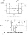
- Circuits B and C illustrated in FIGS. 5A and 5B , respectively, are DC to DC converters 214, 314 with a boost capability only.
- Circuit A consists of an "H" switch bridge having four switch and diode pairs S A and D A , S B and D B , S C and Dc, and S D and D D , coupled to the buck/boost inductor L BB .
- the DC to DC converter 114 circuit allows both buck and boost current in both directions.
- This converter 114 provides a current-controlled type of converter that follows the current demanded from the fuel cell by the inverter (or other load). This circuit provides excellent control of both bucking and boosting voltages with a minimum number of components.
- FIG. 4 shows the DC to DC Converter 114 installed in series with a fuel cell 20 and inverter 16, such as in the Power Management System configuration shown in FIG. 2 , because the converter can transfer power in either direction, the Circuit A converter 114 can also operate in the parallel configuration of FIG. 3 .
- the parallel Power Management System configuration 110 shown in FIG. 3 bi-directional buck and boost capabilities, such as those provided by this converter 114, are required.
- the series configuration 10 illustrated in FIG. 2 however, only a single direction boost capability is required. Of course, many other multi-source power systems are possible which would require the fully bi-directional buck and boost capabilities of the Circuit A converter 114 or a similar converter.
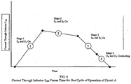
- FIG. 6 is a graph illustrating the current flow over time through the inductor L BB of Circuit A of FIG. 4 .
- Circuit A operates as follows. When switch S A is closed (on) and switch S D is closed (on), current flows from the fuel cell 20 through the inductor L BB to ground. The circuit remains in this state until the inductor L BB is charged to a threshold voltage. This state is shown as stage 1 in FIG. 6 .
- a voltage (or current) monitoring circuit (not shown) monitors the voltage across (or current through) the inductor L BB .
- stage 2 In the boost configuration, the slope of the line in FIG. 6 representing stage 2 is downward and is proportional to the voltage delta across the inductor L BB (i.e., the difference between the input and output voltages), and the current through the inductor L BB is being dissipated.
- the circuit is in the buck configuration (i.e., voltage at the inverter input is reduced below the voltage at the fuel cell output).
- Current and power are still flowing from the fuel cell 20 to the inverter 16 and battery 25, but the slope of the line in FIG. 6 representing stage 2 will be upwards, again in proportion to the voltage delta across the inductor L BB .
- the current through the inductor continues to ramp up until switch S A is opened.
- the converter 114 can be kept in the buck configuration simply by cycling switch S A to allow the current to maintain a steady level.
- switch S A is opened (off) and switches S B and Sc are closed (on). Closing switches S B and S C discharges the remaining energy in the inductor L BB fast without stressing the two diodes D B and Dc. At the same time, however, some current is also flowing through the diodes D B and Dc.
- switches S B and Sc are opened (off), allowing the diodes D B and D C to complete the discharge of the inductor L BB .
- the inductor L BB should be discharged after reaching the end of stage 2 before beginning a new cycle (stage 1). A current from right to left may still be passing through the inductor L BB at the end of stage 2. In other words, a reverse current may still exist in the inductor L BB at this point. If switches S A and S D were simply turned back on and switches Sc and S B turned off, a large forward current would be generated from the fuel cell through the inductor L BB to ground. These two oppositely directed currents could damage the diodes. Accordingly, the inductor L BB is completely discharged before the next boost cycle is started.
- the converter 114 of Circuit A maintains a high current level during stage 2. This high current level increases the RMS current and eliminates the need for generating a large current peak.
- the bi-directional aspect of the converter 114 of Circuit A allows the inductor L BB to be discharged faster (i.e., during stages 3 and 4) between boost cycles (stages 1 and 2).
- Power flow to the fuel cell 20, although not wanted in practice, is also possible using the bi-directional converter 114 of FIG. 4 , and is explained here for illustration. This reverse power flow is potentially desirable for rechargeable DC power sources.
- Power flow to the fuel cell 20 (from right to left) is enabled in the boost configuration by closing switch Sc and cycling S B . It is enabled in the buck configuration by cycling switch Sc.
- a practical application of where power flow from the inverter/battery would be desirable is where the fuel cell is replaced by a second storage device such as a battery.
- a battery bank operating at nominally 24VDC can be used to replace the fuel cell 20.
- the DC to DC converter 114 boosts that voltage to nominally 48VDC, which is the operating voltage of the original battery bank.
- the DC to DC converter 114 bucks the voltage of the original battery bank to 24VDC, for instance, to recharge the battery that replaced the fuel cell.
- a novel method of substantially decreasing the peak to RMS current ratio is also provided.
- This method is enabled, for instance, by using four parallel gate (or switch) and diode pairs.
- the use of four parallel gate and diode pairs allows the converter 114 of Circuit A to reduce the current peak and tailor the shape of the current flowing through the inductor L BB during each cycle. This is accomplished by operating pairs of switches for the first three stages of the cycle. During stage 1, the switches S A and S D are on. During stage 2, the switches S A and S C are on. And, during stage 3, switches S B and Sc are on. During the fourth and final stage (stage 4), current is conducted through diodes D B and Dc only.
- the cycle can be constructed of three stages rather than four, with the first two stages being the same as the first two stages described previously and with the third stage being that of conducting current through diodes D B and Dc only.
- the third stage of the four stage process could be eliminated, if desired, to create a three stage process.
- Boost only DC to DC Converter circuits 214, 314 are shown in FIGS. 5A and 5B , respectively. These converter circuits represent a significant improvement to the conventional converter circuit design described in the technical paper: Duarte, Claudio Manoel da Cunha and Ivo Barbi, "A New Family of ZVS-PSW Active- Clamping DC-to-DC Boost Converters: Analysis, Design, and Experimentation" IEEE Transactions on Power Electronics, Vol. 12, No. 5, September 1997, pp 824-831 (the "Duarte paper”) (see FIG. 5C ).
- Circuit B, shown in FIG. 5A , and Circuit C, shown in FIG. 5B are designed to be zero-voltage switching (ZVS) pulse-width modulation (PWM) active-clamping DC to DC boost converters.
- the circuits are based on the "boost-buck-boost" circuit shown in Figure 1(c) of the Duarte paper.
- the general circuit configuration shown in Figure 1(c) of the Duarte paper is reproduced here as FIG. 5C .
- power is transferred to the load during a boost stage, while the clamping action is performed during a buck-boost stage.
- 5A , 5B, and 5C differ from earlier conventional boost pulse-width modulation (PWM) converters because of the incorporation of an additional auxiliary switch (S 2 ), a resonant inductor (L R ), a resonant capacitor (C R1 ) (which includes the output capacitance of the power switches), and a clamping capacitor Cc.
- switch S 1 is the main switch.
- Voltage V S is the input voltage and voltage V 0 is the output voltage.
- Inductor L R and capacitor C R1 are the resonant circuit inductor and capacitor, respectively.
- Inductor L B is the boost inductor.
- the converters 214, 314 of Circuits B and C each offer an improved design over that of the prior art circuit 414. More specifically, an additional capacitor is included in each of Circuits B and C to achieving soft switching and reliable current control for low voltage (e.g., less than about 100V) and high current (e.g., up to around 150A) applications.
- the circuits developed and described by Duarte and Barbi are primarily aimed at high voltage (i.e., around 300V ⁇ 400V), low current (i.e., around 5A) applications, and because of the low current involved, do not contemplate the need for additional capacitors for satisfactory switching.
- the two converters 214, 314 of FIGS. 5A and 5B are able to offer improved performance over prior art DC to DC converter circuits, such as the one 414 illustrated in FIG. 5C , in low voltage/high current applications.
- the DC to DC converter 214 of Circuit B includes the addition of a capacitor C R2 on the output side of the resonant circuit across the auxilliary switch S 2 .
- the second resonant capacitor C R2 is beneficial in low voltage and high current applications such as fuel cell and battery systems because it substantially reduces output DC current ripple and switching losses and provides better control for combined low voltage/high current applications.
- Circuit B The principle of operation of Circuit B is as follows.
- the inductance in the boost inductor L B is assumed to be large enough for the inductor to act as a current source (Is).
- the clamping capacitor Cc is selected to have a large capacitance so that the voltage Vc across this capacitor can be considered a constant.
- the main and auxiliary switches S 1 and S 2 are switched in a complementary way.
- the main switch S 1 Before time t o , the main switch S 1 is on and the auxiliary switch S 2 is off.
- the resonant capacitor C R1 When S 1 is turned off at time to, the resonant capacitor C R1 is linearly charged, by the boost inductor current Is, to a base voltage V 0 . Due to the presence of the resonant capacitor C R1 , the main switch S 1 is turned off with no switching loss.
- the boost diode D B begins conducting.
- the current through the resonant inductor L R and the resonant capacitor C R1 then evolves in a resonant way, and the resonant capacitor voltage V CR1 rises from the base voltage V 0 up to a increased voltage equal to V Cc + V 0 . At that point, the voltages are clamped. As the capacitor voltage V CR1 becomes equal to V Cc + V 0 , the voltage across the auxiliary switch S 2 is zero, and the switch S 2 turns on with a no loss zero-voltage switching (ZVS). The resonant inductor L R current then ramps down until it reaches zero, when it changes its direction and rises again.
- ZVS no loss zero-voltage switching
- stage 5 the main switch S 1 is turned on without any switching losses (ZVS), because the first resonant capacitor voltage V CR1 became null.
- the current through the resonant inductor L R changes its polarity and ramps up to reach the boost inductor current I S .
- the diode D B becomes reversibly biased and power is not transferred to the load.
- Circuit B offers an improvement over the prior art by splitting its resonant circuit capacitance between two capacitors C R1 and C R2 to allow zero or low voltage switching by both switches S 1 and S 2 .
- the second resonant capacitor C R2 acts as part of the resonant control circuit that includes the resonant inductor L R and the first resonant capacitor C R1 .
- the oscillation that occurs when the main switch S 1 is switched on and off can be neutralized using the second capacitor C R2 by selectively switching the auxiliary switch S 2 .
- the second capacitor C R2 is substantially smaller than the first capacitor C R1 , oscillation control can be provided at low voltage.
- the voltage on switches S 1 and S 2 can be ramped down to allow zero voltage switching. Furthermore, because the capacitors store the voltages with no voltage losses, they provide efficient power transfer between the input and the output nodes of the converter 214.
- the DC to DC converter 314 of Circuit C is another boost converter embodiment capable of use in the Power Management System 10 of FIG. 2 .
- this converter 314 an input capacitor C 1 has been added to the input side of the resonant circuit of the prior art converter 414 of FIG. 5C . Without the capacitor C 1 , the voltage at node A dips in high current applications, and large voltage swings occur at that node. These voltage swings cause a large voltage stress on switch S 1 and result in an inability to achieve reliable control of the current through the resonant inductor L R .
- capacitor C 1 in the circuit, the voltage at node A can be held steady during switching. Because the input capacitor C 1 maintains a constant voltage at node A, the voltage stress on the main switch S 1 is reduced. Specifically, by dampening the voltage swings at node A, the input capacitor C 1 filters out high voltage swings and keeps them from affecting the switch S 1 . This steady voltage at node A helps achieve soft switching and good current control.
Landscapes
- Engineering & Computer Science (AREA)
- Power Engineering (AREA)
- Dc-Dc Converters (AREA)
- Supply And Distribution Of Alternating Current (AREA)
Claims (9)
- Stromüberwachungssystem, umfassend:eine Vielzahl von unabhängigen Gleichstromquellen (20, 25), die an einen Gleichstrombus (13) angeschlossen sind; wobei mindestens eine der unabhängigen Gleichstromquellen eine wiederaufladbare Gleichstromquelle (25) umfasst, um Strom an den Gleichstrombus zu liefern und Strom von diesem zu empfangen, und wobei mindestens eine der unabhängigen Gleichstromquellen eine Brennstoffzelle oder ein Photvoltaik- (PV) Anordnung (20) ist;einen Wechselrichter (16), der in Reihe mit der Brennstoffzelle oder das PV-Modul (20) mit dem Gleichstrombus (13) gekoppelt ist;einen DC/DC-Wandler (114), der zwischen den wiederaufladbaren Gleichstromquellen (25) und dem Gleichstrombus (13) in Reihe und zwischen der Brennstoffzelle oder das PV-Modul (20) und dem Wechselrichter (16) parallel geschaltet ist, wobei der DC/DC-Wandler (114) konfiguriert ist, um anhand von Stromübertragungsverbindungen Strom zwischen dem Gleichstrombus und den wiederaufladbaren Gleichstromquellen bidirektional zu übertragen, undeinen System-Controller (12) zum Überwachen der Stromübertragung zwischen den mehreren unabhängigen Gleichstromquellen und dem Gleichstrombus.
- Stromüberwachungssystem nach Anspruch 1, wobei der DC/DC-Wandler (114) konfiguriert ist, um eine Gleichstrommenge, die der Gleichstrombus (13) aus der Brennstoffzelle oder das PV-Modul (20) an die wiederaufladbaren Gleichstromquellen (25) liefert, zu regeln, und um eine Gleichstrommenge, die der Gleichstrombus (13) von den wiederaufladbaren Gleichstromquellen (25) empfängt und an den Wechselrichter (16) liefert, zu regeln.
- Stromüberwachungssystem nach Anspruch 1, wobei der DC/DC-Wandler (114) einen Auf-/Abwärts-Wandler umfasst.
- Stromüberwachungssystem nach Anspruch 1, wobei:wenn die mindestens eine der unabhängigen Gleichstromquellen die Brennstoffzelle (20) ist, das Stromüberwachungssystem einen Brennstoffzellen-Controller (22) umfasst; oderwenn die mindestens eine der unabhängigen Gleichstromquellen das PV-Modul (20) ist, das Stromüberwachungssystem einen PV-Modul-Controller (22) umfasst.
- Stromüberwachungssystem nach Anspruch 4, wobei der System-Controller (12) konfiguriert ist, um
wenn die mindestens eine der unabhängigen Gleichstromquellen die Brennstoffquelle (20) ist, mit dem Brennstoffzellen-Controller (22) zu kommunizieren, um die Strommenge zu regeln, die von der Brennstoffzelle (20) an den Gleichstrombus (13) geliefert wird; oder
wenn die mindestens eine der unabhängigen Gleichstromquellen das PV-Modul (20) ist, mit dem PV-Modul-Controller (22) zu kommunizieren, um die Strommenge zu regeln, die von dem PV-Modul (20) an den Gleichstrombus (13) geliefert wird. - Stromüberwachungssystem nach Anspruch 1, wobei der DC/DC-Wandler (114) ferner eine Wandler-Steuerschaltung (15) umfasst, die konfiguriert ist, um mit dem System-Controller (12) zu kommunizieren, um eine Strommenge, die zwischen dem DC/DC-Wandler (114) und dem Gleichstrombus (13) übertragen wird, zu regeln.
- Verfahren zum Überwachen mehrerer unabhängiger Gleichstromquellen, umfassend folgende Schritte.
Anordnen einer Vielzahl von unabhängigen Gleichstromquellen, die mit einem Gleichstrombus in Verbindung stehen; wobei mindestens eine der unabhängigen Gleichstromquellen eine wiederaufladbare Gleichstromquelle umfasst, und wobei ferner mindestens eine der unabhängigen Gleichstromquellen eine Brennstoffquelle oder ein PV-Modul umfasst;
Umwandeln einer Spannung von einer oder mehreren der unabhängigen Gleichstromquellen, um sich an eine Spannung des Gleichstrombusses anzupassen; wobei das Umwandeln der Spannung von einer oder mehreren der unabhängigen Gleichstromquellen, um sich an die Spannung des Gleichstrombusses anzupassen, das Anordnen eines DC/DC-Wandlers in Reihe zwischen einer oder mehreren wiederaufladbaren Gleichstromquellen und dem Gleichstrombus und parallel zwischen der Brennstoffzelle oder dem PV-Modul und einem Wechselrichter umfasst; und
Regeln einer Gleichstrommenge, die der Gleichstrombus von der Brennstoffzelle oder dem PV-Modul an eine oder mehrere der wiederaufladbaren Gleichstromquellen liefert, und Regeln einer Gleichstrommenge, die der Gleichstrombus von den wiederaufladbaren Gleichstromquellen empfängt, um sie an den Wechselrichter zu liefern. - Verfahren zum Überwachen mehrerer unabhängiger Gleichstromquellen nach Anspruch 7, wobei das Regeln der Gleichstrommenge, die der Gleichstrombus an eine oder mehrere der unabhängigen Gleichstromquellen liefert oder davon empfängt, das Integrieren zwischen einer Vielzahl von Modi umfasst, wobei jede der Gleichstromquellen entweder einen Teil oder den gesamten Gleichstrom liefert, durch eine oder mehrere der anderen Gleichstromquellen wiederaufgeladen wird, oder von dem Gleichstrombus isoliert ist.
- Verfahren zum Überwachen mehrerer unabhängiger Gleichstromquellen nach Anspruch 7, ferner umfassend das Liefern des Gleichstroms von dem Gleichstrombus an den Wechselrichter zum Umwandeln in Wechselstrom, um eine Bereitstellung von Wechselstrom für einen Verbraucher zu ermöglichen.
Applications Claiming Priority (3)
| Application Number | Priority Date | Filing Date | Title |
|---|---|---|---|
| US22159600P | 2000-07-28 | 2000-07-28 | |
| US221596P | 2000-07-28 | ||
| PCT/US2001/023681 WO2002011267A2 (en) | 2000-07-28 | 2001-07-27 | Dc to dc converter and power management system |
Publications (2)
| Publication Number | Publication Date |
|---|---|
| EP1433239A2 EP1433239A2 (de) | 2004-06-30 |
| EP1433239B1 true EP1433239B1 (de) | 2016-03-30 |
Family
ID=22828458
Family Applications (1)
| Application Number | Title | Priority Date | Filing Date |
|---|---|---|---|
| EP01956002.8A Expired - Lifetime EP1433239B1 (de) | 2000-07-28 | 2001-07-27 | Gleichstrom-gleichstromwandler und leistungssteuerungssystem |
Country Status (4)
| Country | Link |
|---|---|
| US (2) | US6628011B2 (de) |
| EP (1) | EP1433239B1 (de) |
| AU (1) | AU2001278046A1 (de) |
| WO (1) | WO2002011267A2 (de) |
Families Citing this family (348)
| Publication number | Priority date | Publication date | Assignee | Title |
|---|---|---|---|---|
| US7003410B2 (en) | 1996-07-29 | 2006-02-21 | Midtronics, Inc. | Electronic battery tester with relative test output |
| US7246015B2 (en) | 1996-07-29 | 2007-07-17 | Midtronics, Inc. | Alternator tester |
| US8872517B2 (en) | 1996-07-29 | 2014-10-28 | Midtronics, Inc. | Electronic battery tester with battery age input |
| US7706991B2 (en) | 1996-07-29 | 2010-04-27 | Midtronics, Inc. | Alternator tester |
| US6850037B2 (en) | 1997-11-03 | 2005-02-01 | Midtronics, Inc. | In-vehicle battery monitor |
| US6566883B1 (en) | 1999-11-01 | 2003-05-20 | Midtronics, Inc. | Electronic battery tester |
| US6885195B2 (en) | 1996-07-29 | 2005-04-26 | Midtronics, Inc. | Method and apparatus for auditing a battery test |
| US8198900B2 (en) | 1996-07-29 | 2012-06-12 | Midtronics, Inc. | Automotive battery charging system tester |
| US6914413B2 (en) | 1996-07-29 | 2005-07-05 | Midtronics, Inc. | Alternator tester with encoded output |
| US6331762B1 (en) * | 1997-11-03 | 2001-12-18 | Midtronics, Inc. | Energy management system for automotive vehicle |
| US7126341B2 (en) | 1997-11-03 | 2006-10-24 | Midtronics, Inc. | Automotive vehicle electrical system diagnostic device |
| US7688074B2 (en) | 1997-11-03 | 2010-03-30 | Midtronics, Inc. | Energy management system for automotive vehicle |
| US7774151B2 (en) | 1997-11-03 | 2010-08-10 | Midtronics, Inc. | Wireless battery monitor |
| US7705602B2 (en) | 1997-11-03 | 2010-04-27 | Midtronics, Inc. | Automotive vehicle electrical system diagnostic device |
| US6871151B2 (en) | 1997-11-03 | 2005-03-22 | Midtronics, Inc. | Electronic battery tester with network communication |
| US8958998B2 (en) | 1997-11-03 | 2015-02-17 | Midtronics, Inc. | Electronic battery tester with network communication |
| US6323650B1 (en) | 1999-04-08 | 2001-11-27 | Midtronics, Inc. | Electronic battery tester |
| US7505856B2 (en) | 1999-04-08 | 2009-03-17 | Midtronics, Inc. | Battery test module |
| US6737831B2 (en) * | 1999-09-01 | 2004-05-18 | Keith S. Champlin | Method and apparatus using a circuit model to evaluate cell/battery parameters |
| US7598744B2 (en) | 2000-03-27 | 2009-10-06 | Midtronics, Inc. | Scan tool for electronic battery tester |
| US8513949B2 (en) | 2000-03-27 | 2013-08-20 | Midtronics, Inc. | Electronic battery tester or charger with databus connection |
| US7598743B2 (en) | 2000-03-27 | 2009-10-06 | Midtronics, Inc. | Battery maintenance device having databus connection |
| US6967484B2 (en) | 2000-03-27 | 2005-11-22 | Midtronics, Inc. | Electronic battery tester with automotive scan tool communication |
| US7398176B2 (en) | 2000-03-27 | 2008-07-08 | Midtronics, Inc. | Battery testers with secondary functionality |
| US6759849B2 (en) | 2000-03-27 | 2004-07-06 | Kevin I. Bertness | Battery tester configured to receive a removable digital module |
| US7446536B2 (en) | 2000-03-27 | 2008-11-04 | Midtronics, Inc. | Scan tool for electronic battery tester |
| US6906523B2 (en) | 2000-09-14 | 2005-06-14 | Midtronics, Inc. | Method and apparatus for testing cells and batteries embedded in series/parallel systems |
| JP4218202B2 (ja) * | 2000-10-04 | 2009-02-04 | トヨタ自動車株式会社 | 燃料電池を有する直流電源 |
| US7479763B2 (en) | 2001-06-22 | 2009-01-20 | Midtronics, Inc. | Apparatus and method for counteracting self discharge in a storage battery |
| US7501795B2 (en) | 2001-06-22 | 2009-03-10 | Midtronics Inc. | Battery charger with booster pack |
| US6794844B2 (en) * | 2001-08-31 | 2004-09-21 | Visteon Global Technologies, Inc. | Method and system for fuel cell control |
| WO2003032429A2 (en) * | 2001-10-12 | 2003-04-17 | Proton Energy Systems, Inc. | Method and system for bridging short duration power interruptions |
| US6941234B2 (en) | 2001-10-17 | 2005-09-06 | Midtronics, Inc. | Query based electronic battery tester |
| US6737762B2 (en) | 2001-10-26 | 2004-05-18 | Onan Corporation | Generator with DC boost for uninterruptible power supply system or for enhanced load pickup |
| US6989651B1 (en) | 2002-03-05 | 2006-01-24 | Jadoo Power Systems, Inc. | Fuel cell power module and system including same |
| US6864669B1 (en) * | 2002-05-02 | 2005-03-08 | O2Micro International Limited | Power supply block with simplified switch configuration |
| US20030227785A1 (en) * | 2002-06-06 | 2003-12-11 | Johnson Robert W. | On-line uninterruptible power supplies with two-relay bypass circuit and methods of operation thereof |
| US20040012368A1 (en) * | 2002-07-17 | 2004-01-22 | Massey Paul G. | Method and apparatus for charging a rechargeable cell |
| JP4058439B2 (ja) * | 2002-09-13 | 2008-03-12 | プロトン エネルギー システムズ,インク. | 電力システム |
| US6590370B1 (en) * | 2002-10-01 | 2003-07-08 | Mti Microfuel Cells Inc. | Switching DC-DC power converter and battery charger for use with direct oxidation fuel cell power source |
| US7170194B2 (en) * | 2002-10-15 | 2007-01-30 | Powerdsine, Ltd. | Configurable multiple power source system |
| WO2004036399A2 (en) * | 2002-10-15 | 2004-04-29 | Powerdsine Ltd. | Direct current power pooling |
| JP3946623B2 (ja) * | 2002-11-29 | 2007-07-18 | 本田技研工業株式会社 | 燃料電池車両の制御装置 |
| US8027759B2 (en) | 2002-11-29 | 2011-09-27 | Honda Motor Co., Ltd. | Fuel cell vehicle system |
| DE10394007T5 (de) | 2002-12-31 | 2006-02-02 | Midtronics, Inc., Willowbrook | Vorrichtung und Verfahren zum Vorhersagen der verbleibenden Entladezeit einer Batterie |
| US7786616B2 (en) * | 2003-02-07 | 2010-08-31 | Cummins Power Generation Inc. | Generator with DC boost and split bus bidirectional DC-to-DC converter for uninterruptible power supply system or for enhanced load pickup |
| US6891378B2 (en) | 2003-03-25 | 2005-05-10 | Midtronics, Inc. | Electronic battery tester |
| DE10318172B4 (de) * | 2003-04-22 | 2005-12-08 | Webasto Ag | Elektrisches Bordnetz mit Brennstoffzelle und Verfahren zum Betreiben eines elektrischen Verbrauchers in einem solchen Bordnetz |
| EP1620937A1 (de) * | 2003-04-29 | 2006-02-01 | NuCellSys GmbH | Stromwandlerarchitektur und verfahren für integrierte stromversorgungen auf brennstoffzellenbasis |
| US20040217732A1 (en) * | 2003-04-29 | 2004-11-04 | Ballard Power Systems Inc. | Power converter architecture and method for integrated fuel cell based power supplies |
| WO2004107543A2 (en) | 2003-05-28 | 2004-12-09 | Beacon Power Corporation | Power converter for a solar panel |
| US7408358B2 (en) | 2003-06-16 | 2008-08-05 | Midtronics, Inc. | Electronic battery tester having a user interface to configure a printer |
| US6913483B2 (en) | 2003-06-23 | 2005-07-05 | Midtronics, Inc. | Cable for electronic battery tester |
| US7482091B2 (en) * | 2003-07-09 | 2009-01-27 | The Gillette Company | Fuel cartridge interconnect for portable fuel cells |
| US7319304B2 (en) | 2003-07-25 | 2008-01-15 | Midtronics, Inc. | Shunt connection to a PCB of an energy management system employed in an automotive vehicle |
| JP2005078925A (ja) * | 2003-08-29 | 2005-03-24 | Toshiba Corp | 電池ユニットおよび給電制御方法 |
| US9018958B2 (en) | 2003-09-05 | 2015-04-28 | Midtronics, Inc. | Method and apparatus for measuring a parameter of a vehicle electrical system |
| US9255955B2 (en) | 2003-09-05 | 2016-02-09 | Midtronics, Inc. | Method and apparatus for measuring a parameter of a vehicle electrical system |
| US7154276B2 (en) | 2003-09-05 | 2006-12-26 | Midtronics, Inc. | Method and apparatus for measuring a parameter of a vehicle electrical system |
| US8164343B2 (en) | 2003-09-05 | 2012-04-24 | Midtronics, Inc. | Method and apparatus for measuring a parameter of a vehicle electrical system |
| US7977914B2 (en) | 2003-10-08 | 2011-07-12 | Midtronics, Inc. | Battery maintenance tool with probe light |
| US7299368B2 (en) * | 2003-10-16 | 2007-11-20 | Microsemi Corp.-Analog Mixed Signal Group Ltd. | High power architecture for power over Ethernet |
| US7492059B2 (en) * | 2003-10-16 | 2009-02-17 | Microsemi Corp.—Analog Mixed Signal Group Ltd. | High power architecture for power over ethernet |
| US7460889B2 (en) * | 2003-10-16 | 2008-12-02 | Microsemi Corp.—Analog Mixed Signal Group Ltd. | High power classification for power over Ethernet |
| US7595643B2 (en) | 2003-11-11 | 2009-09-29 | Midtronics, Inc. | Apparatus and method for simulating a battery tester with a fixed resistance load |
| US7087329B2 (en) * | 2003-11-19 | 2006-08-08 | Utc Fuel Cells, Llc | Electric storage augmentation of fuel cell system transient response |
| US20050136317A1 (en) * | 2003-12-19 | 2005-06-23 | 3M Innovative Properties Company | Molded multi-part flow field structure |
| US7509114B2 (en) * | 2004-01-22 | 2009-03-24 | Microsemi Corp. - Analog Mixed Signal Group Ltd. | Redundant powered device circuit |
| US7316242B2 (en) | 2004-02-12 | 2008-01-08 | Proton Energy Systems, Inc | Hydrogen storage system and method of operation thereof |
| US20050181244A1 (en) * | 2004-02-12 | 2005-08-18 | Proton Energy Systems, Inc. | Regenerative fuel cell system and method of operation thereof |
| US7598699B2 (en) | 2004-02-20 | 2009-10-06 | Midtronics, Inc. | Replaceable clamp for electronic battery tester |
| US7339353B1 (en) | 2004-03-10 | 2008-03-04 | Quallion Llc | Power system for managing power from multiple power sources |
| US20050218199A1 (en) * | 2004-03-31 | 2005-10-06 | Crevier Robert W | Video Postcard |
| US7777612B2 (en) | 2004-04-13 | 2010-08-17 | Midtronics, Inc. | Theft prevention device for automotive vehicle service centers |
| US7119686B2 (en) | 2004-04-13 | 2006-10-10 | Midtronics, Inc. | Theft prevention device for automotive vehicle service centers |
| US7642786B2 (en) | 2004-06-01 | 2010-01-05 | Midtronics, Inc. | Battery tester capable of identifying faulty battery post adapters |
| US20050286191A1 (en) * | 2004-06-28 | 2005-12-29 | Pieter Vorenkamp | Power supply integrated circuit with multiple independent outputs |
| US9192772B1 (en) | 2004-06-29 | 2015-11-24 | Quallion Llc | Portable medical power system |
| US7772850B2 (en) | 2004-07-12 | 2010-08-10 | Midtronics, Inc. | Wireless battery tester with information encryption means |
| US7106070B2 (en) | 2004-07-22 | 2006-09-12 | Midtronics, Inc. | Broad-band low-inductance cables for making Kelvin connections to electrochemical cells and batteries |
| US7432687B2 (en) * | 2004-08-02 | 2008-10-07 | Electrovaya Inc. | High efficiency switching power supply |
| US8436619B2 (en) | 2004-08-20 | 2013-05-07 | Midtronics, Inc. | Integrated tag reader and environment sensor |
| US8344685B2 (en) | 2004-08-20 | 2013-01-01 | Midtronics, Inc. | System for automatically gathering battery information |
| US9496720B2 (en) | 2004-08-20 | 2016-11-15 | Midtronics, Inc. | System for automatically gathering battery information |
| US8442877B2 (en) | 2004-08-20 | 2013-05-14 | Midtronics, Inc. | Simplification of inventory management |
| US20060071630A1 (en) * | 2004-09-27 | 2006-04-06 | Lockheed Martin Corporation | Hybrid power system |
| US20060068239A1 (en) * | 2004-09-30 | 2006-03-30 | Yasuaki Norimatsu | Electric power source apparatus using fuel cell and method of controlling the same |
| JP4855743B2 (ja) * | 2004-09-30 | 2012-01-18 | 株式会社日立製作所 | 燃料電池を用いた電源装置およびその制御方法 |
| US7663267B2 (en) | 2004-10-05 | 2010-02-16 | Lg Electronics Inc. | Voltage controller for use in electronic appliance using a plurality of power sources and method thereof |
| WO2006061894A1 (ja) * | 2004-12-08 | 2006-06-15 | Mitsubishi Denki Kabushiki Kaisha | 電源装置 |
| US7710119B2 (en) | 2004-12-09 | 2010-05-04 | Midtronics, Inc. | Battery tester that calculates its own reference values |
| US7545146B2 (en) | 2004-12-09 | 2009-06-09 | Midtronics, Inc. | Apparatus and method for predicting battery capacity and fitness for service from a battery dynamic parameter and a recovery voltage differential |
| US7498767B2 (en) | 2005-02-16 | 2009-03-03 | Midtronics, Inc. | Centralized data storage of condition of a storage battery at its point of sale |
| US7873340B2 (en) * | 2005-03-10 | 2011-01-18 | Qualcomm Incorporated | Method to track analog gain step magnitudes online during operation of wireless mobile devices |
| JP4783580B2 (ja) * | 2005-03-31 | 2011-09-28 | 本田技研工業株式会社 | 燃料電池の電気システム、燃料電池車両及び電力供給方法 |
| JP4514143B2 (ja) * | 2005-03-31 | 2010-07-28 | 本田技研工業株式会社 | 電源装置およびその制御方法 |
| JP4555136B2 (ja) * | 2005-03-31 | 2010-09-29 | 本田技研工業株式会社 | 燃料電池の電気システム、燃料電池車両及び電力供給方法 |
| KR100630933B1 (ko) * | 2005-04-15 | 2006-10-02 | 삼성전자주식회사 | 외부전원의 공급 여부에 따라 디스플레이부로의 전원 공급경로가 변하는 전자장치 |
| KR100823921B1 (ko) * | 2005-09-30 | 2008-04-22 | 엘지전자 주식회사 | 연료전지의 전력변환장치 |
| US7522841B2 (en) * | 2005-10-21 | 2009-04-21 | Nortel Networks Limited | Efficient data transmission and training of data processing functions |
| WO2007050577A2 (en) * | 2005-10-24 | 2007-05-03 | The Board Of Trustees Of The University Of Illinois | Fuel-cell based power generating system having power conditioning apparatus |
| JP2007137299A (ja) * | 2005-11-21 | 2007-06-07 | Toyota Motor Corp | 電源供給制御装置 |
| US11881814B2 (en) | 2005-12-05 | 2024-01-23 | Solaredge Technologies Ltd. | Testing of a photovoltaic panel |
| US10693415B2 (en) | 2007-12-05 | 2020-06-23 | Solaredge Technologies Ltd. | Testing of a photovoltaic panel |
| US8103892B2 (en) * | 2006-04-26 | 2012-01-24 | Adaptive Materials, Inc. | Power management apparatus with buck boost converter module |
| US20070273214A1 (en) * | 2006-05-23 | 2007-11-29 | Wang Kon-King M | System and method for connecting power sources to a power system |
| US7588847B2 (en) * | 2006-06-09 | 2009-09-15 | Gm Global Technology Operations, Inc. | Advanced controls concept for hybrid fuel cell systems |
| US7808125B1 (en) | 2006-07-31 | 2010-10-05 | Sustainable Energy Technologies | Scheme for operation of step wave power converter |
| GB0615562D0 (en) * | 2006-08-04 | 2006-09-13 | Ceres Power Ltd | Power supply control for power |
| US7829229B1 (en) * | 2006-08-15 | 2010-11-09 | Gm Global Technology Operations, Inc. | Power control for hybrid fuel cell systems |
| US20080085430A1 (en) * | 2006-10-10 | 2008-04-10 | Macbain John A | Battery integration and control in an auxiliary power unit powered by a solid oxide fuel cell system |
| US7701082B2 (en) * | 2006-10-30 | 2010-04-20 | Honeywell International Inc. | Aerospace electrical power DC subsystem configuration using multi-functional DC/DC converter |
| WO2008063461A1 (en) * | 2006-11-13 | 2008-05-29 | Battelle Memorial Institute | Fuel cell power management module |
| KR100805591B1 (ko) * | 2006-11-16 | 2008-02-20 | 삼성에스디아이 주식회사 | 연료 전지 시스템 및 그 구동 제어 방법 |
| US8013472B2 (en) | 2006-12-06 | 2011-09-06 | Solaredge, Ltd. | Method for distributed power harvesting using DC power sources |
| US11569659B2 (en) | 2006-12-06 | 2023-01-31 | Solaredge Technologies Ltd. | Distributed power harvesting systems using DC power sources |
| US8473250B2 (en) | 2006-12-06 | 2013-06-25 | Solaredge, Ltd. | Monitoring of distributed power harvesting systems using DC power sources |
| US8618692B2 (en) | 2007-12-04 | 2013-12-31 | Solaredge Technologies Ltd. | Distributed power system using direct current power sources |
| US12316274B2 (en) | 2006-12-06 | 2025-05-27 | Solaredge Technologies Ltd. | Pairing of components in a direct current distributed power generation system |
| US11888387B2 (en) | 2006-12-06 | 2024-01-30 | Solaredge Technologies Ltd. | Safety mechanisms, wake up and shutdown methods in distributed power installations |
| US9112379B2 (en) | 2006-12-06 | 2015-08-18 | Solaredge Technologies Ltd. | Pairing of components in a direct current distributed power generation system |
| US8816535B2 (en) | 2007-10-10 | 2014-08-26 | Solaredge Technologies, Ltd. | System and method for protection during inverter shutdown in distributed power installations |
| US11296650B2 (en) | 2006-12-06 | 2022-04-05 | Solaredge Technologies Ltd. | System and method for protection during inverter shutdown in distributed power installations |
| US9088178B2 (en) | 2006-12-06 | 2015-07-21 | Solaredge Technologies Ltd | Distributed power harvesting systems using DC power sources |
| US8384243B2 (en) | 2007-12-04 | 2013-02-26 | Solaredge Technologies Ltd. | Distributed power harvesting systems using DC power sources |
| US11855231B2 (en) | 2006-12-06 | 2023-12-26 | Solaredge Technologies Ltd. | Distributed power harvesting systems using DC power sources |
| US8319471B2 (en) | 2006-12-06 | 2012-11-27 | Solaredge, Ltd. | Battery power delivery module |
| US11309832B2 (en) | 2006-12-06 | 2022-04-19 | Solaredge Technologies Ltd. | Distributed power harvesting systems using DC power sources |
| US9130401B2 (en) | 2006-12-06 | 2015-09-08 | Solaredge Technologies Ltd. | Distributed power harvesting systems using DC power sources |
| US8947194B2 (en) | 2009-05-26 | 2015-02-03 | Solaredge Technologies Ltd. | Theft detection and prevention in a power generation system |
| US8319483B2 (en) | 2007-08-06 | 2012-11-27 | Solaredge Technologies Ltd. | Digital average input current control in power converter |
| US8963369B2 (en) | 2007-12-04 | 2015-02-24 | Solaredge Technologies Ltd. | Distributed power harvesting systems using DC power sources |
| US11735910B2 (en) | 2006-12-06 | 2023-08-22 | Solaredge Technologies Ltd. | Distributed power system using direct current power sources |
| US11687112B2 (en) | 2006-12-06 | 2023-06-27 | Solaredge Technologies Ltd. | Distributed power harvesting systems using DC power sources |
| EP2102961A2 (de) * | 2006-12-20 | 2009-09-23 | Techtium Ltd. | Batteriebetriebenes ladegerät |
| US7994657B2 (en) * | 2006-12-22 | 2011-08-09 | Solarbridge Technologies, Inc. | Modular system for unattended energy generation and storage |
| DE102007017820A1 (de) * | 2007-01-16 | 2008-08-07 | Liebherr-Aerospace Lindenberg Gmbh | Energieversorgungssystem eines Luftfahrzeuges |
| US7663342B2 (en) * | 2007-01-26 | 2010-02-16 | Solarbridge Technologies, Inc. | Apparatus, system, and method for controlling multiple power supplies |
| JP5167645B2 (ja) * | 2007-01-30 | 2013-03-21 | 富士通株式会社 | 電子機器および直流電圧変換システム |
| US7791348B2 (en) | 2007-02-27 | 2010-09-07 | Midtronics, Inc. | Battery tester with promotion feature to promote use of the battery tester by providing the user with codes having redeemable value |
| KR20080084372A (ko) * | 2007-03-16 | 2008-09-19 | 삼성전자주식회사 | 계통 연계형 연료 전지 시스템 및 이를 이용하는 부하 |
| US7808375B2 (en) | 2007-04-16 | 2010-10-05 | Midtronics, Inc. | Battery run down indicator |
| US8031495B2 (en) * | 2007-06-04 | 2011-10-04 | Sustainable Energy Technologies | Prediction scheme for step wave power converter and inductive inverter topology |
| TWI407724B (zh) * | 2007-07-17 | 2013-09-01 | Chunghwa Telecom Co Ltd | Telecommunication Machine Room DC Power Resource Management System |
| GB2491304B (en) | 2007-07-17 | 2013-01-09 | Midtronics Inc | Battery tester and electric vehicle |
| US9274157B2 (en) | 2007-07-17 | 2016-03-01 | Midtronics, Inc. | Battery tester for electric vehicle |
| US7755916B2 (en) | 2007-10-11 | 2010-07-13 | Solarbridge Technologies, Inc. | Methods for minimizing double-frequency ripple power in single-phase power conditioners |
| FR2924481B1 (fr) * | 2007-11-29 | 2013-04-26 | Johnson Controls Neige | Distributeur securise d'eau et/ou d'air pour systeme d'enneigement, equipe d'une vanne pilotee par un actionneur electrique |
| US8294451B2 (en) * | 2007-12-03 | 2012-10-23 | Texas Instruments Incorporated | Smart sensors for solar panels |
| US8049523B2 (en) | 2007-12-05 | 2011-11-01 | Solaredge Technologies Ltd. | Current sensing on a MOSFET |
| WO2009073841A1 (en) * | 2007-12-05 | 2009-06-11 | Sunpower, Inc. | Hybrid electrical power source |
| US11264947B2 (en) | 2007-12-05 | 2022-03-01 | Solaredge Technologies Ltd. | Testing of a photovoltaic panel |
| EP2232690B1 (de) | 2007-12-05 | 2016-08-31 | Solaredge Technologies Ltd. | Parallel geschaltete umrichter |
| EP3561881A1 (de) | 2007-12-05 | 2019-10-30 | Solaredge Technologies Ltd. | Prüfung eines fotovoltaikplanels |
| WO2009072075A2 (en) | 2007-12-05 | 2009-06-11 | Solaredge Technologies Ltd. | Photovoltaic system power tracking method |
| EP3496258B1 (de) | 2007-12-05 | 2025-02-05 | Solaredge Technologies Ltd. | Sicherheitsmechanismus in verteilten strominstallationen |
| US8203345B2 (en) | 2007-12-06 | 2012-06-19 | Midtronics, Inc. | Storage battery and battery tester |
| JP4852028B2 (ja) * | 2007-12-21 | 2012-01-11 | 本田技研工業株式会社 | ハイブリッド直流電源システム及び燃料電池車両 |
| US20100283242A1 (en) * | 2007-12-26 | 2010-11-11 | Dooley Kevin A | High Voltage Start of an Engine from a Low Voltage Battery |
| US8748727B2 (en) * | 2008-01-18 | 2014-06-10 | Tenksolar, Inc. | Flat-plate photovoltaic module |
| US8212139B2 (en) * | 2008-01-18 | 2012-07-03 | Tenksolar, Inc. | Thin-film photovoltaic module |
| US8933320B2 (en) | 2008-01-18 | 2015-01-13 | Tenksolar, Inc. | Redundant electrical architecture for photovoltaic modules |
| EP4145691A1 (de) | 2008-03-24 | 2023-03-08 | Solaredge Technologies Ltd. | Schaltwandler mit einem hilfskommutierungsschaltkreis zur nullstromschaltung |
| US8289183B1 (en) | 2008-04-25 | 2012-10-16 | Texas Instruments Incorporated | System and method for solar panel array analysis |
| EP3121922B1 (de) | 2008-05-05 | 2020-03-04 | Solaredge Technologies Ltd. | Gleichstromleistungskombinierer |
| US8279644B2 (en) * | 2008-05-14 | 2012-10-02 | National Semiconductor Corporation | Method and system for providing maximum power point tracking in an energy generating system |
| US9077206B2 (en) | 2008-05-14 | 2015-07-07 | National Semiconductor Corporation | Method and system for activating and deactivating an energy generating system |
| US20090283129A1 (en) * | 2008-05-14 | 2009-11-19 | National Semiconductor Corporation | System and method for an array of intelligent inverters |
| US8139382B2 (en) * | 2008-05-14 | 2012-03-20 | National Semiconductor Corporation | System and method for integrating local maximum power point tracking into an energy generating system having centralized maximum power point tracking |
| US20090295230A1 (en) * | 2008-05-30 | 2009-12-03 | Nokia Corporation | Selective coupling of a powered component |
| US9048353B2 (en) | 2008-07-01 | 2015-06-02 | Perfect Galaxy International Limited | Photovoltaic DC/DC micro-converter |
| WO2010002960A1 (en) * | 2008-07-01 | 2010-01-07 | Satcon Technology Corporation | Photovoltaic dc/dc micro-converter |
| US8854019B1 (en) | 2008-09-25 | 2014-10-07 | Rf Micro Devices, Inc. | Hybrid DC/DC power converter with charge-pump and buck converter |
| US10153383B2 (en) * | 2008-11-21 | 2018-12-11 | National Semiconductor Corporation | Solar string power point optimization |
| US8203294B2 (en) * | 2008-11-25 | 2012-06-19 | GE Aviations Systems LLC | Electric energy storage integrated within or proximate to electrically driven flight control actuators |
| US9166471B1 (en) | 2009-03-13 | 2015-10-20 | Rf Micro Devices, Inc. | 3D frequency dithering for DC-to-DC converters used in multi-mode cellular transmitters |
| US20100232093A1 (en) * | 2009-03-16 | 2010-09-16 | Lockheed Martin Corporation | Mobile Power Supply |
| US20100244573A1 (en) * | 2009-03-31 | 2010-09-30 | Tanay Karnick | Hybrid power delivery system and method |
| WO2010121181A2 (en) * | 2009-04-17 | 2010-10-21 | National Semiconductor Corporation | System and method for over-voltage protection in a photovoltaic system |
| JP5783614B2 (ja) * | 2009-04-17 | 2015-09-24 | ナショナル セミコンダクター コーポレーションNational Semiconductor Corporation | 分散型最大パワーポイントトラッキングを具備する光起電力システムの過剰電圧保護システム及び方法 |
| US8315576B2 (en) | 2009-05-05 | 2012-11-20 | Rf Micro Devices, Inc. | Capacitive compensation of cascaded directional couplers |
| US20100288327A1 (en) * | 2009-05-13 | 2010-11-18 | National Semiconductor Corporation | System and method for over-Voltage protection of a photovoltaic string with distributed maximum power point tracking |
| JP2012527767A (ja) | 2009-05-22 | 2012-11-08 | ソラレッジ テクノロジーズ リミテッド | 電気絶縁された熱放散接続箱 |
| CN102460799B (zh) * | 2009-06-09 | 2014-12-10 | 丰田自动车株式会社 | 燃料电池系统 |
| IN2012DN00387A (de) * | 2009-06-15 | 2015-08-21 | Tenksolar Inc | |
| US8638011B2 (en) | 2009-07-10 | 2014-01-28 | Protonex Technology Corporation | Portable power manager operating methods |
| US8279642B2 (en) | 2009-07-31 | 2012-10-02 | Solarbridge Technologies, Inc. | Apparatus for converting direct current to alternating current using an active filter to reduce double-frequency ripple power of bus waveform |
| US8462518B2 (en) | 2009-10-12 | 2013-06-11 | Solarbridge Technologies, Inc. | Power inverter docking system for photovoltaic modules |
| US20110084646A1 (en) * | 2009-10-14 | 2011-04-14 | National Semiconductor Corporation | Off-grid led street lighting system with multiple panel-storage matching |
| US12418177B2 (en) | 2009-10-24 | 2025-09-16 | Solaredge Technologies Ltd. | Distributed power system using direct current power sources |
| US8421400B1 (en) | 2009-10-30 | 2013-04-16 | National Semiconductor Corporation | Solar-powered battery charger and related system and method |
| US8710699B2 (en) | 2009-12-01 | 2014-04-29 | Solaredge Technologies Ltd. | Dual use photovoltaic system |
| US8824178B1 (en) | 2009-12-31 | 2014-09-02 | Solarbridge Technologies, Inc. | Parallel power converter topology |
| WO2011090096A1 (ja) * | 2010-01-20 | 2011-07-28 | 三洋電機株式会社 | 充放電システムおよび充放電制御装置 |
| US8766696B2 (en) | 2010-01-27 | 2014-07-01 | Solaredge Technologies Ltd. | Fast voltage level shifter circuit |
| US8548398B2 (en) | 2010-02-01 | 2013-10-01 | Rf Micro Devices, Inc. | Envelope power supply calibration of a multi-mode radio frequency power amplifier |
| US9773933B2 (en) | 2010-02-23 | 2017-09-26 | Tenksolar, Inc. | Space and energy efficient photovoltaic array |
| JP4958052B2 (ja) * | 2010-02-24 | 2012-06-20 | ジーイー・メディカル・システムズ・グローバル・テクノロジー・カンパニー・エルエルシー | 系統電力平準化装置および画像診断システム |
| US9588185B2 (en) | 2010-02-25 | 2017-03-07 | Keith S. Champlin | Method and apparatus for detecting cell deterioration in an electrochemical cell or battery |
| US9425487B2 (en) | 2010-03-03 | 2016-08-23 | Midtronics, Inc. | Monitor for front terminal batteries |
| CN101771294B (zh) * | 2010-03-05 | 2012-08-15 | 矽力杰半导体技术(杭州)有限公司 | 集合驱动控制电路及其控制方法 |
| US8324863B2 (en) * | 2010-04-19 | 2012-12-04 | Tesla Motors, Inc. | Trickle charger for high-energy storage systems |
| US8538355B2 (en) | 2010-04-19 | 2013-09-17 | Rf Micro Devices, Inc. | Quadrature power amplifier architecture |
| US8706063B2 (en) | 2010-04-20 | 2014-04-22 | Rf Micro Devices, Inc. | PA envelope power supply undershoot compensation |
| US8542061B2 (en) | 2010-04-20 | 2013-09-24 | Rf Micro Devices, Inc. | Charge pump based power amplifier envelope power supply and bias power supply |
| US9008597B2 (en) | 2010-04-20 | 2015-04-14 | Rf Micro Devices, Inc. | Direct current (DC)-DC converter having a multi-stage output filter |
| US9077405B2 (en) | 2010-04-20 | 2015-07-07 | Rf Micro Devices, Inc. | High efficiency path based power amplifier circuitry |
| US8989685B2 (en) | 2010-04-20 | 2015-03-24 | Rf Micro Devices, Inc. | Look-up table based configuration of multi-mode multi-band radio frequency power amplifier circuitry |
| US8831544B2 (en) | 2010-04-20 | 2014-09-09 | Rf Micro Devices, Inc. | Dynamic device switching (DDS) of an in-phase RF PA stage and a quadrature-phase RF PA stage |
| US8811921B2 (en) | 2010-04-20 | 2014-08-19 | Rf Micro Devices, Inc. | Independent PA biasing of a driver stage and a final stage |
| US9048787B2 (en) | 2010-04-20 | 2015-06-02 | Rf Micro Devices, Inc. | Combined RF detector and RF attenuator with concurrent outputs |
| US8983407B2 (en) | 2010-04-20 | 2015-03-17 | Rf Micro Devices, Inc. | Selectable PA bias temperature compensation circuitry |
| US9553550B2 (en) | 2010-04-20 | 2017-01-24 | Qorvo Us, Inc. | Multiband RF switch ground isolation |
| US8913967B2 (en) * | 2010-04-20 | 2014-12-16 | Rf Micro Devices, Inc. | Feedback based buck timing of a direct current (DC)-DC converter |
| US8983410B2 (en) | 2010-04-20 | 2015-03-17 | Rf Micro Devices, Inc. | Configurable 2-wire/3-wire serial communications interface |
| US8842399B2 (en) | 2010-04-20 | 2014-09-23 | Rf Micro Devices, Inc. | ESD protection of an RF PA semiconductor die using a PA controller semiconductor die |
| US8958763B2 (en) | 2010-04-20 | 2015-02-17 | Rf Micro Devices, Inc. | PA bias power supply undershoot compensation |
| US8699973B2 (en) | 2010-04-20 | 2014-04-15 | Rf Micro Devices, Inc. | PA bias power supply efficiency optimization |
| US8712349B2 (en) | 2010-04-20 | 2014-04-29 | Rf Micro Devices, Inc. | Selecting a converter operating mode of a PA envelope power supply |
| US8559898B2 (en) | 2010-04-20 | 2013-10-15 | Rf Micro Devices, Inc. | Embedded RF PA temperature compensating bias transistor |
| US9900204B2 (en) | 2010-04-20 | 2018-02-20 | Qorvo Us, Inc. | Multiple functional equivalence digital communications interface |
| US9214900B2 (en) | 2010-04-20 | 2015-12-15 | Rf Micro Devices, Inc. | Interference reduction between RF communications bands |
| US9030256B2 (en) | 2010-04-20 | 2015-05-12 | Rf Micro Devices, Inc. | Overlay class F choke |
| US8565694B2 (en) | 2010-04-20 | 2013-10-22 | Rf Micro Devices, Inc. | Split current current digital-to-analog converter (IDAC) for dynamic device switching (DDS) of an RF PA stage |
| US8892063B2 (en) | 2010-04-20 | 2014-11-18 | Rf Micro Devices, Inc. | Linear mode and non-linear mode quadrature PA circuitry |
| US8942650B2 (en) | 2010-04-20 | 2015-01-27 | Rf Micro Devices, Inc. | RF PA linearity requirements based converter operating mode selection |
| US8515361B2 (en) | 2010-04-20 | 2013-08-20 | Rf Micro Devices, Inc. | Frequency correction of a programmable frequency oscillator by propagation delay compensation |
| US9184701B2 (en) | 2010-04-20 | 2015-11-10 | Rf Micro Devices, Inc. | Snubber for a direct current (DC)-DC converter |
| US8913971B2 (en) | 2010-04-20 | 2014-12-16 | Rf Micro Devices, Inc. | Selecting PA bias levels of RF PA circuitry during a multislot burst |
| US8731498B2 (en) | 2010-04-20 | 2014-05-20 | Rf Micro Devices, Inc. | Temperature correcting an envelope power supply signal for RF PA circuitry |
| US8947157B2 (en) | 2010-04-20 | 2015-02-03 | Rf Micro Devices, Inc. | Voltage multiplier charge pump buck |
| US8942651B2 (en) | 2010-04-20 | 2015-01-27 | Rf Micro Devices, Inc. | Cascaded converged power amplifier |
| US9214865B2 (en) | 2010-04-20 | 2015-12-15 | Rf Micro Devices, Inc. | Voltage compatible charge pump buck and buck power supplies |
| US8571492B2 (en) | 2010-04-20 | 2013-10-29 | Rf Micro Devices, Inc. | DC-DC converter current sensing |
| US8811920B2 (en) | 2010-04-20 | 2014-08-19 | Rf Micro Devices, Inc. | DC-DC converter semiconductor die structure |
| US9362825B2 (en) | 2010-04-20 | 2016-06-07 | Rf Micro Devices, Inc. | Look-up table based configuration of a DC-DC converter |
| US9577590B2 (en) | 2010-04-20 | 2017-02-21 | Qorvo Us, Inc. | Dual inductive element charge pump buck and buck power supplies |
| US9229062B2 (en) | 2010-05-27 | 2016-01-05 | Midtronics, Inc. | Electronic storage battery diagnostic system |
| US10046649B2 (en) | 2012-06-28 | 2018-08-14 | Midtronics, Inc. | Hybrid and electric vehicle battery pack maintenance device |
| US8738309B2 (en) | 2010-09-30 | 2014-05-27 | Midtronics, Inc. | Battery pack maintenance for electric vehicles |
| US11740294B2 (en) | 2010-06-03 | 2023-08-29 | Midtronics, Inc. | High use battery pack maintenance |
| JP5829681B2 (ja) | 2010-06-03 | 2015-12-09 | ミッドトロニクス インコーポレイテッド | 電気自動車用バッテリパックのメンテナンス |
| US9299861B2 (en) | 2010-06-15 | 2016-03-29 | Tenksolar, Inc. | Cell-to-grid redundandt photovoltaic system |
| US9419311B2 (en) | 2010-06-18 | 2016-08-16 | Midtronics, Inc. | Battery maintenance device with thermal buffer |
| KR101425136B1 (ko) | 2010-08-10 | 2014-08-04 | 텐케이솔라 인코포레이티드 | 고효율 태양전지판 |
| US9201120B2 (en) | 2010-08-12 | 2015-12-01 | Midtronics, Inc. | Electronic battery tester for testing storage battery |
| US8742722B2 (en) | 2010-08-27 | 2014-06-03 | International Rectifier Corporation | Dynamic power management system and method |
| US8279649B2 (en) | 2010-10-11 | 2012-10-02 | Solarbridge Technologies, Inc. | Apparatus and method for controlling a power inverter |
| US9160408B2 (en) | 2010-10-11 | 2015-10-13 | Sunpower Corporation | System and method for establishing communication with an array of inverters |
| US8503200B2 (en) | 2010-10-11 | 2013-08-06 | Solarbridge Technologies, Inc. | Quadrature-corrected feedforward control apparatus and method for DC-AC power conversion |
| US10673222B2 (en) | 2010-11-09 | 2020-06-02 | Solaredge Technologies Ltd. | Arc detection and prevention in a power generation system |
| US10673229B2 (en) | 2010-11-09 | 2020-06-02 | Solaredge Technologies Ltd. | Arc detection and prevention in a power generation system |
| GB2485527B (en) | 2010-11-09 | 2012-12-19 | Solaredge Technologies Ltd | Arc detection and prevention in a power generation system |
| US10230310B2 (en) | 2016-04-05 | 2019-03-12 | Solaredge Technologies Ltd | Safety switch for photovoltaic systems |
| US9467063B2 (en) | 2010-11-29 | 2016-10-11 | Sunpower Corporation | Technologies for interleaved control of an inverter array |
| US8842454B2 (en) | 2010-11-29 | 2014-09-23 | Solarbridge Technologies, Inc. | Inverter array with localized inverter control |
| GB2486408A (en) | 2010-12-09 | 2012-06-20 | Solaredge Technologies Ltd | Disconnection of a string carrying direct current |
| GB2483317B (en) | 2011-01-12 | 2012-08-22 | Solaredge Technologies Ltd | Serially connected inverters |
| US8599587B2 (en) | 2011-04-27 | 2013-12-03 | Solarbridge Technologies, Inc. | Modular photovoltaic power supply assembly |
| US8611107B2 (en) | 2011-04-27 | 2013-12-17 | Solarbridge Technologies, Inc. | Method and system for controlling a multi-stage power inverter |
| US9065354B2 (en) | 2011-04-27 | 2015-06-23 | Sunpower Corporation | Multi-stage power inverter for power bus communication |
| US20120326516A1 (en) * | 2011-06-27 | 2012-12-27 | Bloom Energy Corporation | Fuel Cell Power Generation System with Isolated and Non-Isolated Buses |
| US8922185B2 (en) | 2011-07-11 | 2014-12-30 | Solarbridge Technologies, Inc. | Device and method for global maximum power point tracking |
| US8570005B2 (en) | 2011-09-12 | 2013-10-29 | Solaredge Technologies Ltd. | Direct current link circuit |
| US8284574B2 (en) | 2011-10-17 | 2012-10-09 | Solarbridge Technologies, Inc. | Method and apparatus for controlling an inverter using pulse mode control |
| JP5887841B2 (ja) * | 2011-11-02 | 2016-03-16 | ソニー株式会社 | 制御システム |
| US10429449B2 (en) | 2011-11-10 | 2019-10-01 | Midtronics, Inc. | Battery pack tester |
| GB2498365A (en) | 2012-01-11 | 2013-07-17 | Solaredge Technologies Ltd | Photovoltaic module |
| GB2498791A (en) | 2012-01-30 | 2013-07-31 | Solaredge Technologies Ltd | Photovoltaic panel circuitry |
| US9853565B2 (en) | 2012-01-30 | 2017-12-26 | Solaredge Technologies Ltd. | Maximized power in a photovoltaic distributed power system |
| GB2498790A (en) | 2012-01-30 | 2013-07-31 | Solaredge Technologies Ltd | Maximising power in a photovoltaic distributed power system |
| US9065505B2 (en) | 2012-01-31 | 2015-06-23 | Rf Micro Devices, Inc. | Optimal switching frequency for envelope tracking power supply |
| DE102012002599B4 (de) * | 2012-02-13 | 2016-03-03 | Refusol Gmbh | Energieerzeugungsanlage mit Wechselrichter und Energiespeichersystem |
| GB2499991A (en) | 2012-03-05 | 2013-09-11 | Solaredge Technologies Ltd | DC link circuit for photovoltaic array |
| EP3499695B1 (de) | 2012-05-25 | 2024-09-18 | Solaredge Technologies Ltd. | Schaltung für verbundene gleichstromquellen |
| US10115841B2 (en) | 2012-06-04 | 2018-10-30 | Solaredge Technologies Ltd. | Integrated photovoltaic panel circuitry |
| US11325479B2 (en) | 2012-06-28 | 2022-05-10 | Midtronics, Inc. | Hybrid and electric vehicle battery maintenance device |
| US9851411B2 (en) | 2012-06-28 | 2017-12-26 | Keith S. Champlin | Suppressing HF cable oscillations during dynamic measurements of cells and batteries |
| US9276635B2 (en) | 2012-06-29 | 2016-03-01 | Sunpower Corporation | Device, system, and method for communicating with a power inverter using power line communications |
| KR20140052525A (ko) * | 2012-10-24 | 2014-05-07 | 삼성전자주식회사 | 배터리를 충전하고 배터리의 전압을 승압하는 회로 및 배터리를 충전하는 방법 |
| US20140278709A1 (en) | 2013-03-14 | 2014-09-18 | Combined Energies LLC | Intelligent CCHP System |
| US9548619B2 (en) | 2013-03-14 | 2017-01-17 | Solaredge Technologies Ltd. | Method and apparatus for storing and depleting energy |
| US9941813B2 (en) | 2013-03-14 | 2018-04-10 | Solaredge Technologies Ltd. | High frequency multi-level inverter |
| US9906039B2 (en) | 2013-03-14 | 2018-02-27 | Combind Energies, LLC | Power system for multiple power sources |
| US9413271B2 (en) | 2013-03-14 | 2016-08-09 | Combined Energies, Llc | Power conversion system with a DC to DC boost converter |
| US9584044B2 (en) | 2013-03-15 | 2017-02-28 | Sunpower Corporation | Technologies for converter topologies |
| EP2779251B1 (de) | 2013-03-15 | 2019-02-27 | Solaredge Technologies Ltd. | Umgehungsmechanismus |
| US9244100B2 (en) | 2013-03-15 | 2016-01-26 | Midtronics, Inc. | Current clamp with jaw closure detection |
| US9564835B2 (en) | 2013-03-15 | 2017-02-07 | Sunpower Corporation | Inverter communications using output signal |
| JP6158562B2 (ja) * | 2013-04-01 | 2017-07-05 | 京セラ株式会社 | 電力変換装置、制御システム、及び制御方法 |
| US10250134B2 (en) | 2013-04-01 | 2019-04-02 | Revision Military Ltd. | Power manager |
| US9312575B2 (en) | 2013-05-16 | 2016-04-12 | Midtronics, Inc. | Battery testing system and method |
| US10843574B2 (en) | 2013-12-12 | 2020-11-24 | Midtronics, Inc. | Calibration and programming of in-vehicle battery sensors |
| US9923289B2 (en) | 2014-01-16 | 2018-03-20 | Midtronics, Inc. | Battery clamp with endoskeleton design |
| US9318974B2 (en) | 2014-03-26 | 2016-04-19 | Solaredge Technologies Ltd. | Multi-level inverter with flying capacitor topology |
| KR101551086B1 (ko) * | 2014-05-02 | 2015-09-08 | 현대자동차주식회사 | 연료전지 비상전원 공급시스템 |
| US10473555B2 (en) | 2014-07-14 | 2019-11-12 | Midtronics, Inc. | Automotive maintenance system |
| US10222397B2 (en) | 2014-09-26 | 2019-03-05 | Midtronics, Inc. | Cable connector for electronic battery tester |
| CA2965364C (en) | 2014-11-11 | 2021-06-08 | Protonex Technology Corporation | Control module for dc power network |
| US10317468B2 (en) | 2015-01-26 | 2019-06-11 | Midtronics, Inc. | Alternator tester |
| US9966676B2 (en) | 2015-09-28 | 2018-05-08 | Midtronics, Inc. | Kelvin connector adapter for storage battery |
| CN105186672A (zh) * | 2015-10-21 | 2015-12-23 | 上海正泰电源系统有限公司 | 一种混合式的电路拓扑结构 |
| US10848067B2 (en) | 2015-11-20 | 2020-11-24 | Galvion Soldier Power, Llc | Power manager with reconfigurable power converting circuits |
| US11258366B2 (en) | 2015-11-20 | 2022-02-22 | Galvion Soldier Power, Llc | Power manager with reconfigurable power converting circuits |
| AU2016355125A1 (en) | 2015-11-20 | 2018-07-05 | David Long | Power manager with reconfigurable power converting circuits |
| US10305321B2 (en) | 2016-02-10 | 2019-05-28 | Eguana Technologies | Automatic recovery control |
| US11139654B2 (en) | 2016-02-10 | 2021-10-05 | Eguana Technologies | Output control and compensation for AC coupled systems |
| US10599113B2 (en) | 2016-03-03 | 2020-03-24 | Solaredge Technologies Ltd. | Apparatus and method for determining an order of power devices in power generation systems |
| CN107153212B (zh) | 2016-03-03 | 2023-07-28 | 太阳能安吉科技有限公司 | 用于映射发电设施的方法 |
| US11081608B2 (en) | 2016-03-03 | 2021-08-03 | Solaredge Technologies Ltd. | Apparatus and method for determining an order of power devices in power generation systems |
| NL2016525B1 (en) * | 2016-03-31 | 2017-11-02 | Bredenoord B V | Mobile ground power unit and method of use. |
| US11018623B2 (en) | 2016-04-05 | 2021-05-25 | Solaredge Technologies Ltd. | Safety switch for photovoltaic systems |
| US12057807B2 (en) | 2016-04-05 | 2024-08-06 | Solaredge Technologies Ltd. | Chain of power devices |
| US11177663B2 (en) | 2016-04-05 | 2021-11-16 | Solaredge Technologies Ltd. | Chain of power devices |
| US10608353B2 (en) | 2016-06-28 | 2020-03-31 | Midtronics, Inc. | Battery clamp |
| US20180056808A1 (en) * | 2016-08-29 | 2018-03-01 | Ten-D Energies, Inc. | Energy management system |
| US11054480B2 (en) | 2016-10-25 | 2021-07-06 | Midtronics, Inc. | Electrical load for electronic battery tester and electronic battery tester including such electrical load |
| US12320857B2 (en) | 2016-10-25 | 2025-06-03 | Midtronics, Inc. | Electrical load for electronic battery tester and electronic battery tester including such electrical load |
| US10551894B2 (en) | 2016-11-03 | 2020-02-04 | Microsoft Technology Licensing, Llc | Dynamic power management in a hybrid dual battery system |
| US20170201170A1 (en) * | 2017-03-26 | 2017-07-13 | Ahmed Fayez Abu-Hajar | Method for generating highly efficient harmonics free dc to ac inverters |
| DE102017115000A1 (de) * | 2017-07-05 | 2019-01-10 | Hochschule Osnabrück | Photovoltaikeinheit, Photovoltaiksystem, Verfahren zum Betrieb einer Photovoltaikeinheit sowie Verfahren zum Betrieb eines Photovoltaiksystems |
| DE102017214445B4 (de) * | 2017-08-18 | 2025-03-20 | Audi Ag | Verfahren zum Betreiben einer Brennstoffzellenanordnung sowie entsprechende Brennstoffzellenanordnung |
| DE102017214440A1 (de) | 2017-08-18 | 2019-02-21 | Audi Ag | Verfahren zum Betreiben einer Brennstoffzellenanordnung sowie entsprechende Brennstoffzellenanordnung |
| AT521314A1 (de) * | 2018-08-23 | 2019-12-15 | Avl List Gmbh | Brennstoffzellenanlage und Verfahren zur Spannungsregelung in der Brennstoffzellenanlage |
| EP4477487A3 (de) | 2018-09-28 | 2025-03-12 | Carrier Corporation | Elektrische architektur zur versorgung einer transportkühleinheit |
| US11513160B2 (en) | 2018-11-29 | 2022-11-29 | Midtronics, Inc. | Vehicle battery maintenance device |
| US11566972B2 (en) | 2019-07-31 | 2023-01-31 | Midtronics, Inc. | Tire tread gauge using visual indicator |
| US11545839B2 (en) | 2019-11-05 | 2023-01-03 | Midtronics, Inc. | System for charging a series of connected batteries |
| US11668779B2 (en) | 2019-11-11 | 2023-06-06 | Midtronics, Inc. | Hybrid and electric vehicle battery pack maintenance device |
| US11474153B2 (en) | 2019-11-12 | 2022-10-18 | Midtronics, Inc. | Battery pack maintenance system |
| US11973202B2 (en) | 2019-12-31 | 2024-04-30 | Midtronics, Inc. | Intelligent module interface for battery maintenance device |
| DE102020216599A1 (de) | 2019-12-31 | 2021-07-01 | Midtronics, Inc. | Intelligente Modulschnittstelle für eine Batteriewartungsvorrichtung |
| US11486930B2 (en) | 2020-01-23 | 2022-11-01 | Midtronics, Inc. | Electronic battery tester with battery clamp storage holsters |
| WO2021188222A2 (en) | 2020-02-06 | 2021-09-23 | Galvion Ltd. | Rugged integrated helmet vision system |
| DE102021112275A1 (de) * | 2021-05-11 | 2022-11-17 | Enertools GmbH | Verfahren und Vorrichtung zur netzunabhängigen Versorgung mit elektrischer Energie |
| US12517178B2 (en) | 2021-05-27 | 2026-01-06 | Midtronics, Inc. | Battery monitoring system |
| US20230029473A1 (en) * | 2021-07-27 | 2023-02-02 | HyFlyer Powertrain, LLC | Reconfigurable series-parallel fuel cell power system enabling optimization of vehicle/aircraft systems |
| US12155263B2 (en) | 2021-08-06 | 2024-11-26 | Galvion Ltd. | Helmet-mounted power system |
| US12555965B2 (en) | 2021-08-24 | 2026-02-17 | Midtronics, Inc. | Power adapter for automotive vehicle maintenance device |
| USD1062615S1 (en) | 2021-12-21 | 2025-02-18 | Galvion Soldier Power, Llc | Power pack |
| US12330513B2 (en) | 2022-02-14 | 2025-06-17 | Midtronics, Inc. | Battery maintenance device with high voltage connector |
| US12392833B2 (en) | 2022-05-09 | 2025-08-19 | Midtronics, Inc. | Electronic battery tester |
| US12326707B2 (en) | 2022-05-16 | 2025-06-10 | Galvion Ltd. | Method and system of providing a uniform messaging platform in a heterogeneous environment |
| EP4391276A1 (de) | 2022-12-20 | 2024-06-26 | Abb Schweiz Ag | Stromverteilungsanordnung |
| US20250033481A1 (en) * | 2023-07-24 | 2025-01-30 | Bae Systems Controls Inc. | Exportable power for fuel cell buses |
| US20250083572A1 (en) * | 2023-09-13 | 2025-03-13 | General Electric Deutschland Holding Gmbh | Power source assembly for an aeronautical vehicle |
| WO2025106350A1 (en) * | 2023-11-15 | 2025-05-22 | Hanneman Jr Raymond J | Electrical power generator system employing at least one linear harmonic resonance oscillator and at least one flywheel |
| US20260031724A1 (en) * | 2024-07-24 | 2026-01-29 | General Electric Deutschland Holding Gmbh | Power source assembly for aeronautical vehicle |
Citations (4)
| Publication number | Priority date | Publication date | Assignee | Title |
|---|---|---|---|---|
| US4636931A (en) * | 1985-06-28 | 1987-01-13 | Shikoku Denryoku Kabushiki Kaisha | Photovoltaic power control system |
| WO1996018937A1 (en) * | 1994-12-14 | 1996-06-20 | Kenetech Windpower, Inc. | Grid connected bi-directional converter including a pwm, dc-dc chopper, and energy storage/supply device |
| EP0734111A2 (de) * | 1995-03-24 | 1996-09-25 | France Telecom | Photovoltaische Hochspannungsanlage mit individuellen Speichermitteln |
| WO1998034314A1 (en) * | 1997-01-31 | 1998-08-06 | Silverline Power Conversion, Llc | Uninterruptible power supply |
Family Cites Families (15)
| Publication number | Priority date | Publication date | Assignee | Title |
|---|---|---|---|---|
| US3793578A (en) | 1972-03-13 | 1974-02-19 | Allis Louis Co | Regenerative chopper circuitry |
| US3847941A (en) * | 1973-06-11 | 1974-11-12 | Made Labor Sa | 5-hydroxytryptophan alpha-keto-glutarate and its derivatives |
| US4000003A (en) * | 1976-01-02 | 1976-12-28 | The United States Of America As Represented By The Secretary Of The Army | Fuel cell-secondary cell combination |
| JP2989353B2 (ja) * | 1991-11-29 | 1999-12-13 | 三洋電機株式会社 | ハイブリッド燃料電池システム |
| FR2709873B1 (fr) * | 1993-09-06 | 1995-10-20 | Imra Europe Sa | Générateur de tension à pile à combustible. |
| JP3512540B2 (ja) | 1995-11-22 | 2004-03-29 | オリジン電気株式会社 | スイッチング電源及びその制御方法 |
| US5734258A (en) * | 1996-06-03 | 1998-03-31 | General Electric Company | Bidirectional buck boost converter |
| DE19639279C2 (de) | 1996-09-25 | 2002-01-17 | Daimlerchrysler Rail Systems | Stromrichterschaltung |
| US6096449A (en) * | 1997-11-20 | 2000-08-01 | Avista Labs | Fuel cell and method for controlling same |
| DE19810468A1 (de) * | 1998-03-11 | 1999-09-16 | Daimler Chrysler Ag | Schaltungsanordnung zur elektrischen Energieversorgung eines Netzes, das eine Brennstoffzelle sowie eine Akkumulatoranordnung aufweist |
| JP2000036308A (ja) * | 1998-07-16 | 2000-02-02 | Toyota Motor Corp | 燃料電池システム |
| US6072710A (en) | 1998-12-28 | 2000-06-06 | Philips Electronics North America Corporation | Regulated self-oscillating resonant converter with current feedback |
| US6184593B1 (en) * | 1999-07-29 | 2001-02-06 | Abb Power T&D Company Inc. | Uninterruptible power supply |
| US6188199B1 (en) * | 2000-03-31 | 2001-02-13 | Eldec Corporation | Battery charge optimizing system |
| US6243277B1 (en) * | 2000-05-05 | 2001-06-05 | Rockwell Collins, Inc. | Bi-directional dc to dc converter for energy storage applications |
-
2001
- 2001-07-27 EP EP01956002.8A patent/EP1433239B1/de not_active Expired - Lifetime
- 2001-07-27 US US09/917,256 patent/US6628011B2/en not_active Expired - Lifetime
- 2001-07-27 AU AU2001278046A patent/AU2001278046A1/en not_active Abandoned
- 2001-07-27 WO PCT/US2001/023681 patent/WO2002011267A2/en not_active Ceased
-
2003
- 2003-05-27 US US10/447,168 patent/US6882063B2/en not_active Expired - Lifetime
Patent Citations (4)
| Publication number | Priority date | Publication date | Assignee | Title |
|---|---|---|---|---|
| US4636931A (en) * | 1985-06-28 | 1987-01-13 | Shikoku Denryoku Kabushiki Kaisha | Photovoltaic power control system |
| WO1996018937A1 (en) * | 1994-12-14 | 1996-06-20 | Kenetech Windpower, Inc. | Grid connected bi-directional converter including a pwm, dc-dc chopper, and energy storage/supply device |
| EP0734111A2 (de) * | 1995-03-24 | 1996-09-25 | France Telecom | Photovoltaische Hochspannungsanlage mit individuellen Speichermitteln |
| WO1998034314A1 (en) * | 1997-01-31 | 1998-08-06 | Silverline Power Conversion, Llc | Uninterruptible power supply |
Also Published As
| Publication number | Publication date |
|---|---|
| US20020047309A1 (en) | 2002-04-25 |
| US20030201674A1 (en) | 2003-10-30 |
| WO2002011267A2 (en) | 2002-02-07 |
| WO2002011267A3 (en) | 2004-05-06 |
| EP1433239A2 (de) | 2004-06-30 |
| US6882063B2 (en) | 2005-04-19 |
| AU2001278046A1 (en) | 2002-02-13 |
| US6628011B2 (en) | 2003-09-30 |
Similar Documents
| Publication | Publication Date | Title |
|---|---|---|
| EP1433239B1 (de) | Gleichstrom-gleichstromwandler und leistungssteuerungssystem | |
| Sato et al. | Nonisolated multiport converters based on integration of PWM converter and phase-shift-switched capacitor converter | |
| Chen et al. | A cascaded high step-up DC–DC converter with single switch for microsource applications | |
| Tao et al. | Multi-input bidirectional DC-DC converter combining DC-link and magnetic-coupling for fuel cell systems | |
| Sadeghpour et al. | Integrated three-port converter for solar-charged electric vehicle applications | |
| Sato et al. | Non-isolated multi-port converter integrating PWM and phase-shift converters | |
| Babu et al. | Renewable Energy Applications and a Multi-Input DC-DC Converter for Hybrid Electric Vehicle Applications using Matlab/Simulink | |
| Gokul et al. | Design and control of non-isolated bidirectional DC-DC converter for energy storage application | |
| An et al. | Single-stage boost-integrated full-bridge converter with simultaneous mppt, wide dc motor speed range, and current ripple reduction | |
| Li et al. | Series-connected current-source-mode multiple-output converters with high step-down ratio and simple control | |
| Zhao et al. | A design of single-switch two-stage DC-DC converters with PWM and PFM for off-grid solar power system | |
| Pacheco et al. | A DC-DC converter adequate for alternative supply system applications | |
| Chandran et al. | A high voltage gain multiport zeta-zeta converter for renewable energy systems | |
| Govind et al. | A Review of High-Gain Bidirectional DC-DC converter with reduced ripple current | |
| Kumar et al. | Implementation of Bi-directional DC-DC converter for PV energy system | |
| Jung et al. | A multiple-input SEPIC with a bi-directional input for modular distributed generation and energy storage integration | |
| Mohsenzadeh et al. | A review of step-up DC-DC multiport converters, topologies, techniques, features, and applications part I: non-isolated structures | |
| Kanhav et al. | A reliable multiple input DC-DC converter for hybrid power system | |
| Suresh et al. | EV Battery Charging Using Bi-Directional Converter With Buck Mode | |
| Mahobiya et al. | Comparative Analysis of Multiport Boost Converter and Z-Source Multiport Converter for EV Charging | |
| Elshora et al. | Modular Bidirectional Converter with Multiple Power Sources for Fast Charging of Electric Vehicles | |
| CN117175941B (zh) | Buck-Boost直流变换器及复合电源系统 | |
| Ali et al. | A high gain variable boost DC-DC converter for low-voltage hybrid direct methanol fuel cell batteries | |
| Alhani | Design and implementation of multi-port DC-DC converters for electrical power systems | |
| Cheng | Topology Derivation and Development of Non-Isolated Three-port Converters for DC Microgrids |
Legal Events
| Date | Code | Title | Description |
|---|---|---|---|
| PUAI | Public reference made under article 153(3) epc to a published international application that has entered the european phase |
Free format text: ORIGINAL CODE: 0009012 |
|
| 17P | Request for examination filed |
Effective date: 20030227 |
|
| AK | Designated contracting states |
Kind code of ref document: A2 Designated state(s): AT BE CH CY DE DK ES FI FR GB GR IE IT LI LU MC NL PT SE TR |
|
| RIC1 | Information provided on ipc code assigned before grant |
Ipc: 7H 02J 7/34 A Ipc: 7H 02M 3/158 B |
|
| 17Q | First examination report despatched |
Effective date: 20110715 |
|
| RIC1 | Information provided on ipc code assigned before grant |
Ipc: H02M 3/155 20060101ALI20150827BHEP Ipc: H02M 3/158 20060101ALI20150827BHEP Ipc: H02M 1/34 20070101ALI20150827BHEP Ipc: H02J 7/34 20060101AFI20150827BHEP |
|
| GRAP | Despatch of communication of intention to grant a patent |
Free format text: ORIGINAL CODE: EPIDOSNIGR1 |
|
| INTG | Intention to grant announced |
Effective date: 20151005 |
|
| GRAS | Grant fee paid |
Free format text: ORIGINAL CODE: EPIDOSNIGR3 |
|
| GRAA | (expected) grant |
Free format text: ORIGINAL CODE: 0009210 |
|
| AK | Designated contracting states |
Kind code of ref document: B1 Designated state(s): AT BE CH CY DE DK ES FI FR GB GR IE IT LI LU MC NL PT SE TR |
|
| REG | Reference to a national code |
Ref country code: GB Ref legal event code: FG4D |
|
| REG | Reference to a national code |
Ref country code: CH Ref legal event code: EP |
|
| REG | Reference to a national code |
Ref country code: AT Ref legal event code: REF Ref document number: 786334 Country of ref document: AT Kind code of ref document: T Effective date: 20160415 |
|
| REG | Reference to a national code |
Ref country code: IE Ref legal event code: FG4D |
|
| REG | Reference to a national code |
Ref country code: DE Ref legal event code: R096 Ref document number: 60149839 Country of ref document: DE |
|
| REG | Reference to a national code |
Ref country code: FR Ref legal event code: PLFP Year of fee payment: 16 |
|
| PG25 | Lapsed in a contracting state [announced via postgrant information from national office to epo] |
Ref country code: FI Free format text: LAPSE BECAUSE OF FAILURE TO SUBMIT A TRANSLATION OF THE DESCRIPTION OR TO PAY THE FEE WITHIN THE PRESCRIBED TIME-LIMIT Effective date: 20160330 Ref country code: GR Free format text: LAPSE BECAUSE OF FAILURE TO SUBMIT A TRANSLATION OF THE DESCRIPTION OR TO PAY THE FEE WITHIN THE PRESCRIBED TIME-LIMIT Effective date: 20160701 |
|
| REG | Reference to a national code |
Ref country code: NL Ref legal event code: MP Effective date: 20160330 |
|
| REG | Reference to a national code |
Ref country code: AT Ref legal event code: MK05 Ref document number: 786334 Country of ref document: AT Kind code of ref document: T Effective date: 20160330 |
|
| PG25 | Lapsed in a contracting state [announced via postgrant information from national office to epo] |
Ref country code: SE Free format text: LAPSE BECAUSE OF FAILURE TO SUBMIT A TRANSLATION OF THE DESCRIPTION OR TO PAY THE FEE WITHIN THE PRESCRIBED TIME-LIMIT Effective date: 20160330 |
|
| PG25 | Lapsed in a contracting state [announced via postgrant information from national office to epo] |
Ref country code: NL Free format text: LAPSE BECAUSE OF FAILURE TO SUBMIT A TRANSLATION OF THE DESCRIPTION OR TO PAY THE FEE WITHIN THE PRESCRIBED TIME-LIMIT Effective date: 20160330 |
|
| PGFP | Annual fee paid to national office [announced via postgrant information from national office to epo] |
Ref country code: DE Payment date: 20160720 Year of fee payment: 16 Ref country code: GB Payment date: 20160727 Year of fee payment: 16 |
|
| PG25 | Lapsed in a contracting state [announced via postgrant information from national office to epo] |
Ref country code: ES Free format text: LAPSE BECAUSE OF FAILURE TO SUBMIT A TRANSLATION OF THE DESCRIPTION OR TO PAY THE FEE WITHIN THE PRESCRIBED TIME-LIMIT Effective date: 20160330 Ref country code: PT Free format text: LAPSE BECAUSE OF FAILURE TO SUBMIT A TRANSLATION OF THE DESCRIPTION OR TO PAY THE FEE WITHIN THE PRESCRIBED TIME-LIMIT Effective date: 20160801 Ref country code: AT Free format text: LAPSE BECAUSE OF FAILURE TO SUBMIT A TRANSLATION OF THE DESCRIPTION OR TO PAY THE FEE WITHIN THE PRESCRIBED TIME-LIMIT Effective date: 20160330 |
|
| PG25 | Lapsed in a contracting state [announced via postgrant information from national office to epo] |
Ref country code: BE Free format text: LAPSE BECAUSE OF FAILURE TO SUBMIT A TRANSLATION OF THE DESCRIPTION OR TO PAY THE FEE WITHIN THE PRESCRIBED TIME-LIMIT Effective date: 20160330 |
|
| REG | Reference to a national code |
Ref country code: DE Ref legal event code: R097 Ref document number: 60149839 Country of ref document: DE |
|
| PG25 | Lapsed in a contracting state [announced via postgrant information from national office to epo] |
Ref country code: DK Free format text: LAPSE BECAUSE OF FAILURE TO SUBMIT A TRANSLATION OF THE DESCRIPTION OR TO PAY THE FEE WITHIN THE PRESCRIBED TIME-LIMIT Effective date: 20160330 |
|
| PLBE | No opposition filed within time limit |
Free format text: ORIGINAL CODE: 0009261 |
|
| STAA | Information on the status of an ep patent application or granted ep patent |
Free format text: STATUS: NO OPPOSITION FILED WITHIN TIME LIMIT |
|
| REG | Reference to a national code |
Ref country code: CH Ref legal event code: PL |
|
| 26N | No opposition filed |
Effective date: 20170103 |
|
| PG25 | Lapsed in a contracting state [announced via postgrant information from national office to epo] |
Ref country code: MC Free format text: LAPSE BECAUSE OF FAILURE TO SUBMIT A TRANSLATION OF THE DESCRIPTION OR TO PAY THE FEE WITHIN THE PRESCRIBED TIME-LIMIT Effective date: 20160330 |
|
| PG25 | Lapsed in a contracting state [announced via postgrant information from national office to epo] |
Ref country code: LI Free format text: LAPSE BECAUSE OF NON-PAYMENT OF DUE FEES Effective date: 20160731 Ref country code: CH Free format text: LAPSE BECAUSE OF NON-PAYMENT OF DUE FEES Effective date: 20160731 |
|
| REG | Reference to a national code |
Ref country code: IE Ref legal event code: MM4A |
|
| REG | Reference to a national code |
Ref country code: FR Ref legal event code: PLFP Year of fee payment: 17 |
|
| PG25 | Lapsed in a contracting state [announced via postgrant information from national office to epo] |
Ref country code: IE Free format text: LAPSE BECAUSE OF NON-PAYMENT OF DUE FEES Effective date: 20160727 |
|
| PGFP | Annual fee paid to national office [announced via postgrant information from national office to epo] |
Ref country code: FR Payment date: 20170613 Year of fee payment: 17 |
|
| PG25 | Lapsed in a contracting state [announced via postgrant information from national office to epo] |
Ref country code: LU Free format text: LAPSE BECAUSE OF NON-PAYMENT OF DUE FEES Effective date: 20160727 |
|
| PGFP | Annual fee paid to national office [announced via postgrant information from national office to epo] |
Ref country code: IT Payment date: 20170720 Year of fee payment: 17 |
|
| REG | Reference to a national code |
Ref country code: DE Ref legal event code: R119 Ref document number: 60149839 Country of ref document: DE |
|
| GBPC | Gb: european patent ceased through non-payment of renewal fee |
Effective date: 20170727 |
|
| PG25 | Lapsed in a contracting state [announced via postgrant information from national office to epo] |
Ref country code: GB Free format text: LAPSE BECAUSE OF NON-PAYMENT OF DUE FEES Effective date: 20170727 Ref country code: DE Free format text: LAPSE BECAUSE OF NON-PAYMENT OF DUE FEES Effective date: 20180201 |
|
| PG25 | Lapsed in a contracting state [announced via postgrant information from national office to epo] |
Ref country code: CY Free format text: LAPSE BECAUSE OF FAILURE TO SUBMIT A TRANSLATION OF THE DESCRIPTION OR TO PAY THE FEE WITHIN THE PRESCRIBED TIME-LIMIT Effective date: 20160330 |
|
| PG25 | Lapsed in a contracting state [announced via postgrant information from national office to epo] |
Ref country code: TR Free format text: LAPSE BECAUSE OF FAILURE TO SUBMIT A TRANSLATION OF THE DESCRIPTION OR TO PAY THE FEE WITHIN THE PRESCRIBED TIME-LIMIT Effective date: 20160330 |
|
| PG25 | Lapsed in a contracting state [announced via postgrant information from national office to epo] |
Ref country code: FR Free format text: LAPSE BECAUSE OF NON-PAYMENT OF DUE FEES Effective date: 20180731 |
|
| PG25 | Lapsed in a contracting state [announced via postgrant information from national office to epo] |
Ref country code: IT Free format text: LAPSE BECAUSE OF NON-PAYMENT OF DUE FEES Effective date: 20180727 |