US11258366B2 - Power manager with reconfigurable power converting circuits - Google Patents
Power manager with reconfigurable power converting circuits Download PDFInfo
- Publication number
- US11258366B2 US11258366B2 US17/081,716 US202017081716A US11258366B2 US 11258366 B2 US11258366 B2 US 11258366B2 US 202017081716 A US202017081716 A US 202017081716A US 11258366 B2 US11258366 B2 US 11258366B2
- Authority
- US
- United States
- Prior art keywords
- power
- external
- converter
- voltage
- energy management
- Prior art date
- Legal status (The legal status is an assumption and is not a legal conclusion. Google has not performed a legal analysis and makes no representation as to the accuracy of the status listed.)
- Active
Links
Images


Classifications
-
- H—ELECTRICITY
- H02—GENERATION; CONVERSION OR DISTRIBUTION OF ELECTRIC POWER
- H02J—ELECTRIC POWER NETWORKS; CIRCUIT ARRANGEMENTS OR SYSTEMS FOR SUPPLYING OR DISTRIBUTING ELECTRIC POWER; SYSTEMS FOR STORING ELECTRIC ENERGY
- H02J1/00—Circuit arrangements for DC mains or DC distribution networks
- H02J1/10—Parallel operation of DC sources
- H02J1/102—Parallel operation of DC sources being switching converters
-
- G—PHYSICS
- G06—COMPUTING OR CALCULATING; COUNTING
- G06F—ELECTRIC DIGITAL DATA PROCESSING
- G06F1/00—Details not covered by groups G06F3/00 - G06F13/00 and G06F21/00
- G06F1/26—Power supply means, e.g. regulation thereof
- G06F1/263—Arrangements for using multiple switchable power supplies, e.g. battery and AC
-
- G—PHYSICS
- G06—COMPUTING OR CALCULATING; COUNTING
- G06F—ELECTRIC DIGITAL DATA PROCESSING
- G06F1/00—Details not covered by groups G06F3/00 - G06F13/00 and G06F21/00
- G06F1/26—Power supply means, e.g. regulation thereof
- G06F1/266—Arrangements to supply power to external peripherals either directly from the computer or under computer control, e.g. supply of power through the communication port, computer controlled power-strips
-
- G—PHYSICS
- G06—COMPUTING OR CALCULATING; COUNTING
- G06F—ELECTRIC DIGITAL DATA PROCESSING
- G06F13/00—Interconnection of, or transfer of information or other signals between, memories, input/output devices or central processing units
- G06F13/38—Information transfer, e.g. on bus
- G06F13/40—Bus structure
- G06F13/4004—Coupling between buses
- G06F13/4022—Coupling between buses using switching circuits, e.g. switching matrix, connection or expansion network
-
- H—ELECTRICITY
- H02—GENERATION; CONVERSION OR DISTRIBUTION OF ELECTRIC POWER
- H02J—ELECTRIC POWER NETWORKS; CIRCUIT ARRANGEMENTS OR SYSTEMS FOR SUPPLYING OR DISTRIBUTING ELECTRIC POWER; SYSTEMS FOR STORING ELECTRIC ENERGY
- H02J1/00—Circuit arrangements for DC mains or DC distribution networks
- H02J1/08—Three-wire DC power distribution systems; Systems having more than three wires
-
- H—ELECTRICITY
- H02—GENERATION; CONVERSION OR DISTRIBUTION OF ELECTRIC POWER
- H02J—ELECTRIC POWER NETWORKS; CIRCUIT ARRANGEMENTS OR SYSTEMS FOR SUPPLYING OR DISTRIBUTING ELECTRIC POWER; SYSTEMS FOR STORING ELECTRIC ENERGY
- H02J7/00—Circuit arrangements for charging or discharging batteries or for supplying loads from batteries
- H02J7/34—Parallel operation in networks using both storage and other DC sources, e.g. providing buffering
-
- H—ELECTRICITY
- H02—GENERATION; CONVERSION OR DISTRIBUTION OF ELECTRIC POWER
- H02J—ELECTRIC POWER NETWORKS; CIRCUIT ARRANGEMENTS OR SYSTEMS FOR SUPPLYING OR DISTRIBUTING ELECTRIC POWER; SYSTEMS FOR STORING ELECTRIC ENERGY
- H02J7/00—Circuit arrangements for charging or discharging batteries or for supplying loads from batteries
- H02J7/50—Circuit arrangements for charging or discharging batteries or for supplying loads from batteries acting upon multiple batteries simultaneously or sequentially
- H02J7/52—Circuit arrangements for charging or discharging batteries or for supplying loads from batteries acting upon multiple batteries simultaneously or sequentially for charge balancing, e.g. equalisation of charge between batteries
- H02J7/56—Active balancing, e.g. using capacitor-based, inductor-based or DC-DC converters
-
- H—ELECTRICITY
- H02—GENERATION; CONVERSION OR DISTRIBUTION OF ELECTRIC POWER
- H02J—ELECTRIC POWER NETWORKS; CIRCUIT ARRANGEMENTS OR SYSTEMS FOR SUPPLYING OR DISTRIBUTING ELECTRIC POWER; SYSTEMS FOR STORING ELECTRIC ENERGY
- H02J7/00—Circuit arrangements for charging or discharging batteries or for supplying loads from batteries
- H02J7/865—Battery or charger load switching, e.g. concurrent charging and load supply
-
- H—ELECTRICITY
- H02—GENERATION; CONVERSION OR DISTRIBUTION OF ELECTRIC POWER
- H02M—APPARATUS FOR CONVERSION BETWEEN AC AND AC, BETWEEN AC AND DC, OR BETWEEN DC AND DC, AND FOR USE WITH MAINS OR SIMILAR POWER SUPPLY SYSTEMS; CONVERSION OF DC OR AC INPUT POWER INTO SURGE OUTPUT POWER; CONTROL OR REGULATION THEREOF
- H02M3/00—Conversion of DC power input into DC power output
- H02M3/02—Conversion of DC power input into DC power output without intermediate conversion into AC
- H02M3/04—Conversion of DC power input into DC power output without intermediate conversion into AC by static converters
-
- H—ELECTRICITY
- H02—GENERATION; CONVERSION OR DISTRIBUTION OF ELECTRIC POWER
- H02M—APPARATUS FOR CONVERSION BETWEEN AC AND AC, BETWEEN AC AND DC, OR BETWEEN DC AND DC, AND FOR USE WITH MAINS OR SIMILAR POWER SUPPLY SYSTEMS; CONVERSION OF DC OR AC INPUT POWER INTO SURGE OUTPUT POWER; CONTROL OR REGULATION THEREOF
- H02M3/00—Conversion of DC power input into DC power output
- H02M3/22—Conversion of DC power input into DC power output with intermediate conversion into AC
- H02M3/24—Conversion of DC power input into DC power output with intermediate conversion into AC by static converters
- H02M3/28—Conversion of DC power input into DC power output with intermediate conversion into AC by static converters using discharge tubes with control electrode or semiconductor devices with control electrode to produce the intermediate AC
- H02M3/285—Single converters with a plurality of output stages connected in parallel
-
- H—ELECTRICITY
- H02—GENERATION; CONVERSION OR DISTRIBUTION OF ELECTRIC POWER
- H02J—ELECTRIC POWER NETWORKS; CIRCUIT ARRANGEMENTS OR SYSTEMS FOR SUPPLYING OR DISTRIBUTING ELECTRIC POWER; SYSTEMS FOR STORING ELECTRIC ENERGY
- H02J1/00—Circuit arrangements for DC mains or DC distribution networks
- H02J1/08—Three-wire DC power distribution systems; Systems having more than three wires
- H02J1/082—DC supplies with two or more different DC voltage levels
-
- H—ELECTRICITY
- H02—GENERATION; CONVERSION OR DISTRIBUTION OF ELECTRIC POWER
- H02M—APPARATUS FOR CONVERSION BETWEEN AC AND AC, BETWEEN AC AND DC, OR BETWEEN DC AND DC, AND FOR USE WITH MAINS OR SIMILAR POWER SUPPLY SYSTEMS; CONVERSION OF DC OR AC INPUT POWER INTO SURGE OUTPUT POWER; CONTROL OR REGULATION THEREOF
- H02M1/00—Details of apparatus for conversion
- H02M1/10—Arrangements incorporating converting means for enabling loads to be operated at will from different kinds of power supplies, e.g. from AC or DC
-
- Y—GENERAL TAGGING OF NEW TECHNOLOGICAL DEVELOPMENTS; GENERAL TAGGING OF CROSS-SECTIONAL TECHNOLOGIES SPANNING OVER SEVERAL SECTIONS OF THE IPC; TECHNICAL SUBJECTS COVERED BY FORMER USPC CROSS-REFERENCE ART COLLECTIONS [XRACs] AND DIGESTS
- Y02—TECHNOLOGIES OR APPLICATIONS FOR MITIGATION OR ADAPTATION AGAINST CLIMATE CHANGE
- Y02D—CLIMATE CHANGE MITIGATION TECHNOLOGIES IN INFORMATION AND COMMUNICATION TECHNOLOGIES [ICT], I.E. INFORMATION AND COMMUNICATION TECHNOLOGIES AIMING AT THE REDUCTION OF THEIR OWN ENERGY USE
- Y02D10/00—Energy efficient computing, e.g. low power processors, power management or thermal management
Definitions
- the exemplary, illustrative, technology herein relates to a reconfigurable converter power circuit.
- the reconfigurable converter power circuit includes a single one-way DC to DC power converter, multiple converter channel legs, and multiple switches.
- the reconfigurable converter power circuit can be configured as one of an input power converting channel, and output power converting channel, or a bi-directional bus-compatible power channel by configuring sets of the multiple switches as either open or closed.
- a power manager includes at least one reconfigurable power circuit connected to a device port and connected to a power bus.
- the reconfigurable converter power circuit can be configured to connect the device port to the power bus.
- the reconfigurable converter power circuit can be reconfigured for three different functions: input power signal voltage conversion, output power signal voltage conversion, and input or output power signal with no voltage conversion.
- a power node includes a first power device port and second power device port and a reconfigurable converter power circuit connected to the first power device port and to the second power device port.
- the reconfigurable converter power circuit can be configured to connect the first and second power device ports.
- the reconfigurable converter power circuit can be reconfigured for three different functions: first power device port to second power device port signal voltage conversion, second power device port to first power device port signal voltage conversion, and no voltage conversion between first power device port and second power device port.
- Portable power manager devices are used to scavenge DC power from external power devices, i.e. DC power sources and energy storage devices such as rechargeable DC batteries.
- the scavenged power received from external DC power and energy sources is used to power a power bus operating on the portable power manager.
- External power devices that need power i.e. DC power loads and or energy storage devices such as rechargeable DC batteries are interfaced to the power bus to draw power from the power bus.
- Conventional power managers include a plurality of device ports connected to an internal DC power bus. An external DC power device is connected to a device port. Typically each device port includes a direct connect power channel usable to directly connect an external power device connected to a device port to the power bus without voltage conversion.
- direct connect power channels include a switch, operable by a digital processor operating on the power manager, to directly connect an external DC power device to the power bus or to disconnect the external power device from the power bus.
- each device port includes a direct connect power channel which is bidirectional and can be used to receive input power from an external power device or to deliver output power to an external power device as long as the external power device is compatible with the bus voltage.
- each device port also may be associated with a power converting power channel that includes either an input DC to DC power converter or an output DC to DC power converter and at least one switch operable by the digital processor operating on the power manager to connect an external DC power device to the power bus over the power converter channel or to disconnect the external DC power device from the power bus or to prevent the connection as needed.
- an external DC power device is a non-bus compatible DC power or energy source usable to scavenge input power
- the external device is connected to the power bus over a power converting channel that includes an input power converter.
- an external DC power device is a non-bus compatible DC power load or rechargeable energy storage device that needs to be powered
- the external device is connected to the power bus over an output power DC to DC converter.
- the power manager devices include six device ports that can each be connected to a power bus or disconnected from the power bus by operating switches under the control or a digital process or CPU.
- the power bus operates at a fixed bus voltage which can vary slightly over a range. All six device ports include a direct connect bidirectional power channel that extends from the power bus to the device port.
- Each direct connect power channel includes a switch operable by the digital processor.
- any one of the six device ports can be connected to the power bus over a direct connect power channel when an external power device connected to the device port is a bus voltage compatible device and this includes any DC power source, DC power load, or rechargeable battery that can be operated at the bus compatible voltage.
- the device disclosed by Robinson et al. includes a total of three DC to DC power converters with one power converter arranged as an input power converter and two power converters arranged as output power converters. More specifically the input power converter is shared by two input ports and each of the two output power converters is shared by two output ports.
- One problem with this configuration is that while there are six device ports only three of the six device ports can use one of the three DC to DC power converters at the same time. More specifically only one input device port can be connected to the power bus over an input power converting channel and only two output device ports can be connected to the power bus over an output power converting channel at the same time. In practice this can result in situations where only three device ports or at least less than all six device ports can be utilized.
- This problem can be solved by providing an input power converting channel and an output power converting channel between each device port and the power bus; however, such a device is more costly and increases the weight and device package size. Meanwhile there is a need in the art to decrease the cost weight and package size of conventional portable power managers.
- a reconfigurable power circuit ( 400 ) includes a first electrical connection interface ( 271 ) and a second electrical connection interface ( 272 ).
- a one-way DC to DC power converter ( 220 ) includes an input terminal ( 222 ) for receiving input power at a first power amplitude and an output terminal ( 224 ) for delivering output power at a second power amplitude.
- a plurality of converter channel legs ( 243 , 245 , 247 , and 249 ) is arranged as three different conductive pathways including a first bidirectional current flow path ( 234 , 400 a ) that extends from the first electrical connection interface to the second electrical connection interface.
- the first bidirectional current flow path ( 234 ) does not pass through the DC to DC power converter and does not charge input and output bulk capacitors ( 225 , 226 ).
- the first bidirectional current flow path ( 400 a ) passes through the one-way DC to DC power converter from the input terminal thereof to the output terminal thereof while the DC to DC power converter is configured with a zero-voltage conversion set point.
- the first bidirectional current flow path ( 400 a ) also charges input and output bilk capacitors.
- a second, one-way current flow path ( 232 ) extends from the first electrical connection interface to the input terminal ( 222 ) through the one-way DC to DC power converter ( 220 ) to the output terminal ( 224 ) and from the output terminal to the second electrical connection interface.
- a third one-way current flow path ( 230 ) extending from the second electrical connection interface to the input terminal ( 222 ) through the one-way DC to DC power converter ( 220 ) to the output terminal ( 224 ) and from the output terminal to the first electrical connection interface.
- At least one configurable switch disposed along each one of the plurality of converter channel legs. Closing one or more of the configurable switches and opening one or more others of the configurable switches enables exclusive current flow along one of the first bidirectional current flow path ( 234 , 400 a ), the second, one-way current flow path ( 232 ), and the third one-way current flow path ( 230 )
- the reconfigurable power circuit includes four channel legs ( 243 , 245 , 247 , and 249 ) with one configurable switch ( 253 , 255 , 257 , and 259 ) disposed along each channel leg.
- Exclusive current flow any one of the first bidirectional current flow path ( 234 ), the second, one-way current flow path ( 232 ) or the third one-way current flow path ( 230 ) can be established by closing at two or three of the four configurable switches and by opening two or one other of the four configurable switches.
- the reconfigurable power circuit includes one or more input current sensors ( 262 ) and or one or more input voltage sensors ( 264 ) for measuring input current or voltage amplitude at either side or the input interface ( 222 ) or the output interface ( 224 ) or at either one of the first electrical and second electrical connection interface points.
- the reconfigurable power circuit includes one or more output current sensors ( 265 ) and or one or more output voltage sensors ( 267 ) for measuring input voltage amplitude or output voltage amplitude at either side or the input interface ( 222 ) or the output interface ( 224 ) or at either one of the first electrical and second electrical connection interface points.
- the reconfigurable power circuit can be included in a power manager device ( 500 , 1000 ) configured with one or both of first electrical connection interface ( 271 ) and the second electrical connection interface ( 272 ) as a device port and operated to exchange power between two external DC power devices each connected to a different one of the device ports.
- the first electrical connection interface ( 271 ) is configured as a device port and the second electrical connection interface ( 272 ) electrically interfaced with a DC power bus ( 110 ).
- a plurality of reconfigurable power circuits is interfaced with a DC power bus at second electrical interface and the first electrical interface of each of the plurality of reconfigurable power circuits is configured as a device port.
- a primary device channel ( 153 ) is electrically interfaced with the DC power bus.
- the primary device channel is a bidirectional non power converting channel.
- a primary device port ( 143 ) electrically interfaced with the primary device channel.
- the one-way DC to DC power converter ( 220 ) is operable by an electronic controller to receive input power at a first input power voltage amplitude at the input terminal ( 222 ) and deliver output power from the output terminal ( 224 ) at second output voltage amplitude, different from the first input voltage amplitude.
- the one-way DC to DC power converter is operable by the electronic controller to receive input power at a first input current amplitude at the input terminal ( 222 ) and deliver output power from the output terminal ( 224 ) at second output current amplitude, wherein the second output current amplitude is less than the first input current amplitude.
- a power distribution system ( 1000 ) includes a DC power bus ( 110 ) and a plurality of the reconfigurable power circuits ( 400 a , 400 a ).
- the first electrical connection interface ( 271 ) of each of the plurality of reconfigurable power circuits is configured as a first device port ( 141 , 142 ) and the second electrical connection interface ( 272 ) of each of the plurality of the reconfigurable power circuits is interfaced with a DC power bus ( 110 ).
- a primary device channel ( 153 ) has a first end thereof terminated by a primary device port ( 143 ) and a second end thereof electrically interfaced with the DC power bus with a configurable switch ( 261 ) disposed along the primary device channel.
- a digital data processor ( 120 ) is electrically interfaced with a memory module, with each of the device ports ( 141 , 142 , 143 ) and with all of the controllable switches corresponding with all of the reconfigurable power circuits.
- the digital data processor is also electrically interfaced with the one-way DC to DC power converter of each of the plurality of reconfigurable power circuits.
- At least one sensor is electrically interfaced with the digital data processor and is positioned to measure one of an instantaneous input power amplitude and an instantaneous output power amplitude either at the DC power bus or corresponding with measurement points corresponding with any of the plurality of reconfigurable circuits.
- An energy management schema program is operated on the digital data processor. The system operates to autonomously exchange power between at least two external DC power devices electrically interfaced with any one of the first device port ( 141 , 142 ) and the primary device port ( 143 ).
- a Maximum Power Point Tracking (MPPT) module ( 512 ) can be operated by the digital data processor to manage input power from a time variable voltage source such as a solar or wind power generation device.
- the MPPT module operates to provide current attenuation and voltage conversion set points to the one what DC to DC power converter to converts variable voltage input power to substantially non-variable voltage output power.
- An operating method for the reconfigurable circuit for a single reconfigurable circuit that include a device port at each electrical interface point includes evaluating, by the energy management schema, DC power characteristics at each of the electrical interface points.
- the method may include measuring a power condition by one or more sensors or receiving power characteristics data from one or more of the two external DC power devices.
- the method includes selecting, by the energy management schema, based on the DC power characteristic evaluation, one external DC power device as a power source and another external DC power device as a power load.
- the energy management schema determines, based on the DC power characteristic evaluation, a DC to DC voltage conversion setting for operating the one-way DC to DC power converter and selects a configuration of the reconfigurable power circuit that corresponds with the DC to DC voltage conversion setting.
- the configuration of the reconfigurable power circuit includes any one of the first bidirectional current flow path between the device ports, the second, one-way current flow path extending from the first device port to an input terminal of the one-way DC to DC power converter through the one-way DC to DC power converter to an output terminal of the one-way DC to DC power converter to the second device port or the third one-way current flow path extending from the second device port to the input terminal through the one-way DC to DC power converter to the output terminal and from the output terminal to the first device port.
- FIG. 1 depicts an exemplary schematic diagram of a non-limiting exemplary power manager according to one aspect of the present invention.
- FIG. 2 depicts a perspective view of a non-limiting exemplary power manager according to one aspect of the present invention.
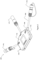
- FIG. 3 depicts a perspective view of a non-limiting exemplary cable assembly according to one aspect of the present invention.
- FIG. 4 depicts an exemplary schematic diagram of a non-limiting exemplary power manager according to one aspect of the present invention.
- FIG. 5 depicts an exemplary schematic diagram of a non-limiting exemplary power manager according to one aspect of the present invention.
- FIG. 6 depicts an exemplary schematic diagram of a non-limiting exemplary power manager according to one aspect of the present invention.
- FIG. 7 depicts an exemplary schematic diagram of a non-limiting exemplary power manager according to one aspect of the present invention.
- FIG. 8 depicts an exemplary flow diagram depicting a non-limiting exemplary power manager operating mode according to one aspect of the present invention.
- FIG. 9 a depicts an exemplary schematic diagram of a non-limiting exemplary reconfigurable power converter circuit according to one aspect of the present invention.
- FIG. 9 b depicts an alternative exemplary schematic diagram of a non-limiting exemplary reconfigurable power converter circuit according to one aspect of the present invention.
- FIG. 10 depicts an exemplary schematic diagram of a non-limiting exemplary power manager that includes two reconfigurable power converting circuits according to the present invention.
- FIG. 11 depicts an exemplary schematic diagram of a non-limiting exemplary power node according to one aspect of the present invention.
- TERM DEFINITION External Power A DC power load, a DC power source, or a Device re-chargeable DC battery.
- Energy An energy management schema includes Management various programs, firmware algorithms, Schema and policy elements operating on a digital data processor to receive input power into a power manager from one or more device ports and to distribute output to external power devices connected to one or more device ports.
- the power manager ( 100 ) includes a digital data processor ( 120 ) and an associated memory module ( 122 ).
- the digital data processor ( 120 ) includes a programmable logic device operating an energy management schema program and carrying out logical operations such as communicating with external DC power devices ( 161 , 162 , 163 ), connected to device ports ( 141 , 142 , 143 ), managing the memory module ( 122 ) to store and recall data, reading sensor signals from power sensors, altering an operating voltage of a DC power bus ( 110 ), and operating one or more reconfigurable power circuits and related power channel control devices to establish a power network operable to exchange power from one external DC power device to another.
- Power manager ( 100 ) includes a variable voltage DC power bus ( 110 ).
- An operating voltage of the DC power bus ( 110 ) can be set by the digital data processor ( 120 ).
- the operating voltage of the DC power bus ( 110 ) is matched to an operating voltage of an external DC power device ( 163 ) interfaced with a primary device port ( 143 ).
- the primary device port ( 143 ) is connected to the power bus ( 110 ) over a primary power channel that does not include a power converter. Accordingly the operating voltage of the primary external DC power device ( 163 ) is always used to establish the operating voltage of the DC power bus ( 110 ).
- Power manager ( 100 ) includes a bus power sensor module ( 112 ) in electrical communication with DC power bus ( 110 ) and in communication digital data processor ( 120 ) and operable to measure and report instantaneous DC voltage at the DC power bus ( 110 ) to the digital data processor ( 120 ).
- Bus power sensor module ( 112 ) may determine one or more of instantaneous power, instantaneous voltage, and/or instantaneous current amplitude at the DC power bus ( 110 ).
- the power manager ( 100 ) described below includes three device ports; however, any practical implementation that includes two or more device ports is within the scope of the present invention.
- the power manager includes a single primary device port ( 143 ) and one or more secondary device ports ( 141 , 142 ).
- Each device port provides a wired electrical connection interface over which an external DC power device ( 161 , 162 , and 163 ) can be electrically interfaced to the power manager by a wire connection that at least includes a power channel.
- Each device port ( 141 , 142 , 143 ) also includes a communication channel or interface such as SMBus or the like operable to provide a digital communication link between the digital data processor ( 120 ), and an external DC power device electrically interfaced with each device port.
- Each device port ( 141 , 142 , and 143 ) includes a power channel operable to exchange a power signal between the DC power bus ( 110 ) and an external DC power device electrically interfaced to the device port.
- the communication channel can be a wired communication channel or a wireless communication channel.
- the power channel may include an inductive portion for power exchange from the device port to an external DC power device across a non-wire medium.
- power manager ( 200 ) includes a sealed and substantially weather and dust tight power manager device enclosure ( 170 ) including a plurality of enclosure side walls ( 172 ) an enclosure top wall ( 174 ) and an opposing enclosure bottom wall opposed to the top wall ( 174 ).
- the enclosure ( 170 ) encloses components of the power manager ( 100 ) including the digital data processor ( 120 ), the DC power bus ( 110 ), and the power circuits and channels ( 151 , 152 , and 153 ).
- the device ports ( 141 , 142 , and 143 ) are connected to distal ends ( 181 ) of wire cables ( 180 ) that pass through the enclosure side walls ( 172 ) at a proximal end.
- each device port comprises a first physical connector or plug ( 176 , 177 , and 178 ) suitable for connecting to an external power device connected to the distal end ( 181 ) of wire or cable ( 180 ).
- Each first physical connector or plug is suitable for mating with any external DC power device having a comparable second physical connector or plug.
- external DC power devices are easily connected to or disconnected from any one of the first physical connectors to electrically interface with the power manager.
- each device port includes a cable gland ( 184 ) passing through one of the enclosure side walls ( 172 ).
- the wire cables ( 180 ) each preferably comprise a shielded cable wherein a proximal end ( 183 ) of each wire cable passes through a different cable gland ( 184 ) and a distal end ( 181 ) of each the wire cables is terminated by a first physical connector ( 176 , 177 , and 178 ).
- Each cable gland ( 184 ) passes through an aperture passing through an enclosure side wall ( 172 ) and is attached to and mechanically supported by the enclosure side wall ( 172 ).
- Each wire cable ( 180 ) includes conductive elements ( 186 ) enclosed by a cable shielding layer which is further enclosed by an electrically insulating cable outer covering. Some of the conductive elements ( 186 ) at the proximate end of each wire cable are electrically interfaced with one of the power channels ( 151 , 152 , and 153 ) which provide a conductive path to the DC power bus ( 110 ). Some of the conductive elements ( 186 ) at the proximal end of each wire cable may be electrically interfaced with one of the communication channels ( 130 ).
- each wire cable is electrically interfaced with a different first physical connector ( 141 , 142 , and 143 ) which includes one or more power channels and may include one or more wired communication channels.
- a different first physical connector 141 , 142 , and 143
- Each cable ( 180 ) enters the cable gland ( 183 ) from outside the enclosure side wall ( 172 ) and the cable shielding layer and the electrically insulating cable outer covering the shielding layer are gripped by the cable gland ( 184 ) in a manner that electrically grounds the cable shielding layer to a corresponding enclosure sidewall ( 172 ) and secures the distal end to the cable gland.
- a similar cable gland ( 184 ), cable and enclosure wall interface is disclosed in commonly owned U.S.
- the power manager ( 100 ) includes a communication network ( 130 ).
- the communication channel ( 130 ) includes one or more network or similar communication interface devices ( 114 ) and a plurality of communication channels interconnecting various internal devices and modules to the digital data processor ( 120 ) for digital communication.
- the communication channel ( 130 ) optionally includes additional network communication interface devices ( 114 ) operable to communicate with other power managers, e.g. over a peer-to-peer network, as well as to gain access to a Wide Area Network (WAN), e.g. over a cellular network interface device, and or to communicate with WAN based devices such a policy server, authentication module or the like, operating on one or more WAN based servers.
- WAN Wide Area Network
- Each wireless network interface device ( 114 ) is configured to receive communication signals configured in a first communication protocol structure and to translate the first communication protocol signals to a second communication protocol structure as needed to facilitate communication between devices configured to use different communication protocols.
- the communication channels also may extend between internal modules of the power manager ( 100 ) without passing over the digital data processor ( 120 ) and may include analog channels for exchanging analog signals including power signals.
- Each device port ( 141 , 142 , and 143 ) is connected with the digital data processor ( 120 ) over at least one communication network channel. Accordingly when an external power device is connected with any one of the device ports the external DC power device joins the communication network established by the communication interface device ( 114 ) for communication with the digital data processor ( 120 ).
- the communication channel ( 130 ) optionally includes a variety of communication channel types, e.g. using different network protocols, suitable for digital data communications.
- the communication channel types may include analog signal conductors or the like for exchanging analog signals between electronic modules operating on the power manager ( 100 ).
- the communication channel ( 130 ) is primarily a wired communication network housed inside the enclosure ( 170 ).
- Wireless communication channels are optionally provided such that in some embodiment's wireless communication channels are usable to communicate with external DC power devices or with other power managers and with network devices reachable on a Wide Area Network (WAN).
- WAN Wide Area Network
- the various communication channel types may include one or more of a wired network using a wire network communication protocol, e.g. the IEEE 802.3 wired Local Area Networks (LAN) protocols which include Ethernet and Power over Ethernet (PoE), System Management Bus (SMBus), Universal Serial Bus (USB), Recommended Standard 232 (RS232), or the like.
- the various communication channel types may include wireless networks based on any one of the IEEE 802.11 Wireless Local Area Network (WLAN) protocols which include Wi-Fi, Bluetooth, or any one of the IEEE 802.11 WLAN protocols, and one or more cellular network protocols e.g. 3G, 4G, LTE, etc.
- the communication channel ( 130 ) may include conductive paths, wires or the like, for exchanging analog or digital signals between electronic components of the power manager such as various switches, sensors, and power converters and the digital data processor ( 120 ).
- the communication channel ( 130 ) extends from the digital data processor ( 120 ) to each controllable element of the power manager ( 100 ) including switching elements ( 253 , 255 , 257 , 259 , 261 ), the DC power bus sensor ( 112 ), other power sensors ( 210 , 211 , and 212 ) and power converters ( 220 , 221 ) to deliver control signals thereto and to receive sensor signals, or the like, therefrom.
- the control signals include configuration and setting instructions for operating each controllable element to receive and distribute power according to the energy management schema.
- the communication channels extending to device ports may comprise a one-wire identification interface configured to enable the digital data processor ( 120 ) to query a connected external power device ( 161 , 162 , and 163 ) for power characteristics information.
- the power manager ( 100 ) includes an optional internal rechargeable battery ( 116 ). If present, the internal battery ( 116 ) provides power to the digital data processor ( 120 ).
- the internal battery is a rechargeable battery ( 116 ) that can be charged when the power manager ( 100 ) is operably connected to a power source or external battery capable of providing charge.
- the internal battery ( 116 ) provides power to digital data processor ( 120 ), enabling the functioning of the power manager ( 100 ), when power sufficient for operation of the power manager is not available from a power source or rechargeable battery connected to a device port ( 161 , 162 , 163 ).
- power sensors ( 210 , 212 ) are operable to detect an operating voltage and or input power available from a connected external power source or rechargeable DC battery without any communication with the external device and to use the available input power to operate the digital data processor ( 120 ) or recharge the internal battery ( 116 ).
- power manager ( 100 ) includes a primary device port ( 143 ) which is electrically connectable to a primary external DC power device ( 163 ) and a DC power bus ( 110 ).
- the primary external DC power device ( 163 ) is any external DC power device that can be connected to any one of the primary device port ( 143 ) or the secondary device ports ( 141 ) or ( 142 ).
- the primary power channel ( 153 ) includes only one power channel extending from the primary device port ( 143 ) to the DC power bus ( 110 ) and is configurable a as bi-directional power channel operable as an input power channel or as an output power channel without voltage or power conversion and without current attenuation.
- Primary power channel ( 153 ) includes a bidirectional conductor or primary leg ( 251 ) that extends between primary device port ( 143 ) and DC power bus ( 110 ) and allows current flow either from the primary external DC power device ( 163 ) to the DC power bus ( 110 ) or from the DC power bus ( 110 ) to the primary external DC power device ( 163 ).
- a primary configurable switch ( 261 ) is disposed along primary leg ( 251 ) between the primary device port ( 143 ) and DC power bus ( 110 ).
- Digital data processor ( 120 ) is in communication with primary configurable switch ( 261 ) over the communication channel ( 130 ) and is operable to send control signals to the primary configurable switch ( 261 ).
- Digital data processor ( 120 ) can set primary configurable switch ( 261 ) in an open position to block flow of current over the primary leg ( 251 ) or in a closed position to allow an input power signal to pass from primary device port ( 143 ) to DC power bus ( 110 ) or to allow an output power signal to pass from power bus ( 110 ) to the primary external DC power device ( 163 ) over the primary device port ( 110 ), thereby connecting primary external DC power device ( 163 ) to DC power bus ( 110 ).
- Primary power channel ( 153 ) optionally includes a primary channel power sensor module ( 212 ) associated with primary device port ( 143 ) and in communication with digital data processor ( 120 ) over the communication channel ( 130 ).
- the primary channel power sensor module ( 212 ) is configured to measure power characteristics of power signals passing over the primary power channel ( 153 ) including one or more of instantaneous power amplitude, instantaneous voltage amplitude, and instantaneous current amplitude and to report amplitude measurement results to digital data processor ( 120 ).
- the power manager ( 100 ) further includes at least one and in the present embodiment two converter or secondary device ports ( 141 , 142 ) each of which is electrically connectable to a secondary external DC power device ( 161 , 162 ).
- Each secondary external DC power device ( 161 , 162 ) is any external DC power device that can be connected to any one of the primary device port ( 143 ) or the secondary device ports ( 141 ) or ( 142 ).
- Each reconfigurable power circuit ( 151 , 152 ) extends between a different converter or device port ( 141 , 142 ) and the DC power bus ( 110 ).
- Each reconfigurable power circuit ( 151 , 152 ) is independently operated by the digital data processor ( 120 ) as needed to transfer power between a connected secondary external DC power device ( 161 , 162 ) and the DC power bus ( 110 ) or to transfer power from the DC power bus ( 110 ) to the connected secondary external DC power device ( 161 , 162 ).
- Each converter device port ( 141 , 142 ) includes a communication channel, operably connectable to an external secondary DC power device ( 161 , 162 ) interfaced therewith. The communication channel is part of the communication channel ( 130 ), which enables communications between the digital data processor ( 120 ) and each of the secondary external DC power device ( 161 , 162 ) interfaced with a converter device port ( 141 , 142 ).
- the reconfigurable converter power circuits ( 151 , 152 ) each include one or more secondary power channels or conductors that extends from a different converter or secondary device port ( 141 , 142 ) to the DC power bus ( 110 ). Each secondary power channel includes a different one-way DC to DC power converter ( 220 , 221 ) disposed between a corresponding device port and the DC power bus.
- Each reconfigurable converter power circuit ( 151 , 152 ) includes power channel circuitry that is configurable to provide any one of a one-way power converting input power channel ( 232 ), shown in FIG. 6 , a one-way power converting output power channel ( 230 ), shown in FIG. 5 , and a bidirectional power channel ( 234 ), shown in FIG. 7 wherein the bidirectional power channel ( 234 ) is usable as an input power channel or an output power channel without voltage conversion.
- Each reconfigurable converter power channel ( 151 , 152 ) includes a different converter circuit power sensor module ( 210 , 211 ).
- Each converter circuit power sensor module is disposed proximate to a corresponding converter device port ( 141 , 142 ) in order to sense power characteristic of power signals either entering or exiting the converter device port ( 141 , 142 ).
- Each converter circuit power sensor module is in communication with the digital data processor ( 120 ) and is operable to measure power characteristics of a bidirectional power signal including one or more of instantaneous power, instantaneous voltage, and instantaneous current and to report measurement results to the digital data processor ( 120 ).
- Each controllable one-way DC to DC voltage or power converter ( 220 , 221 ) includes an input terminal ( 222 ) and an output terminal ( 224 ).
- Each DC to DC power converter ( 220 , 221 ) is one-way because a power signal can only be power converted or current modulated when the power signal is directed from the input terminal ( 222 ) to the output terminal ( 224 ).
- a power signal entering through the input terminal ( 222 ) is power converted and or current modulated according to power conversion and amplitude modulation settings received from the digital data processor ( 120 ).
- the power converted output signal exiting output terminal ( 224 ) has one of a different voltage or a different current amplitude, or both and may have a different total power amplitude as compared to the input power signal.
- the DC to DC power converter ( 220 ) can be configured to convert in input signal voltage to a different output signal voltage by either stepping the input voltage up or stepping the input voltage down as required to adjust the output signal voltage exiting from the output terminal ( 224 ) to a desired voltage amplitude.
- the DC to DC power converter is further configured to modulate the current amplitude of the input power signal as required to adjust the output signal current amplitude exiting from the output terminal ( 224 ) to a desired current amplitude.
- the power converter operates to modulate current amplitude passing over the power converter between substantially zero and a maximum available current amplitude, i.e. the entire instantaneous current amplitude of the input signal is passed through the power converter without modulation.
- the digital data processor ( 120 ) determines if an external DC power device connected to a converter or secondary device port ( 161 , 162 ) is a DC power source, a rechargeable DC battery, or a DC power load, either by communicating with the external DC power device to determine a device type and other information such as the operating voltage range, state of charge, or the like, or by determining an instantaneous voltage based on a sensor signal received from the converter circuit power sensor module ( 210 ).
- the energy management schema operating on the digital data processor makes a determination about whether to connect the external power device to the DC power bus or not and further makes a determination about how to configure the relevant reconfigurable circuit ( 151 , 152 ) to make the connection.
- Each reconfigurable converter power circuit ( 151 , 152 ) includes four configurable switches ( 253 ), ( 255 ), ( 257 ), and ( 259 ). Each configurable switch is operable to direct a power signal over a desired conductive flow path or to prevent the power signal from flowing over the conductive flow path.
- Digital data processor ( 120 ) is in communication with each of the four configurable switches via the communication channel ( 130 ) and is operable to send an independent control signal to each switch.
- Each configurable switch ( 253 , 255 , 257 , and 259 ) can be toggled to an open (off) position, to prevent current flow across the switch or toggled to a closed (on) position to allow current flow across the switch.
- the configurable switch ( 261 ) used in the primary power channel ( 153 ) can be toggled to an open (off) position, to prevent current flow across the switch or toggled to a closed (on) position to allow current flow across the switch.
- configurable switches ( 253 , 255 , 257 , and 259 ) of the reconfigurable power circuits ( 251 , 253 ) and the configurable switch ( 261 ) of the primary power channel ( 153 ) are single pole single throw type switches.
- the switches can be implemented with multiple throws, multiple poles.
- the switches can include Field Effect Transistors (FETs), e.g. MOSFETs, Power FETs, e-MOSFETs, etc.
- each reconfigurable converter power circuit ( 151 , 152 ) includes multiple power channels ( 230 , 232 , and 234 ) each comprising multiple converter channel legs ( 243 , 245 , 247 , and 249 ).
- bidirectional current flow over each leg is indicated by solid double-headed arrows, e.g. as shown on the primary power channel ( 153 ) and one-way current flow over each leg is indicated by solid single headed arrows, e.g. as shown on converter power circuit ( 230 ).
- Converter device port ( 141 , 142 ), DC power bus ( 110 ), switches ( 253 , 255 , 257 , and 259 ) and one-way DC to DC power converter ( 220 ) are interconnected by the converter channel legs ( 243 , 245 , 247 , and 249 ) to provide various current flow paths or circuit configurations as may be required to distribute power to or receive power from an external converter power device connected to a secondary device port.
- Reconfigurable converter power circuits ( 151 , 152 ) are configurable to transfer power signals between converter or secondary device ports ( 141 , 142 ) and the DC power bus ( 110 ) in either direction i.e., from converter device port ( 141 , 142 ) to DC power bus ( 110 ) or from DC power bus ( 110 ) to converter device port ( 141 , 142 ) with or without power conversion by configuring the state of each of the configurable switches ( 253 , 255 , 257 , and 259 ) in patterns of open and closed positions and by configuring the state of each DC to DC power converter ( 120 ) for power converting or non-power converting modes. Patterns of open and closed positions and of on and off configurations are set forth in Table 1.
- FIGS. 5, 6, and 7 patterns of configurable switch open and closed positions, power converter on and off configurations, and corresponding electrical current flow paths are shown for each of the multiple power channels ( 230 , 232 , and 234 ).
- Blackened circles represent closed switches
- bolded power converter ( 220 ) outlines represent “on” state of the power converter
- bolded arrows represent active converter channel legs, i.e. channel legs over which electrical current can flow given the specified patterns of open and closed switch positions and power converter setting.
- Primary power channel ( 153 ) is configured as an input/output power channel by closing primary configurable switch ( 261 ). In this case an input power signal received from a primary external DC power source or rechargeable battery connected to the primary device port ( 143 ) is directed to the DC power bus ( 110 ) without power conversion. Likewise when a primary external power load or rechargeable DC battery to be charged is connected to primary device port ( 143 ) an output power signal received from the DC power bus ( 110 ) is directed to primary device port ( 143 ) without power conversion.
- each reconfigurable converter power circuit ( 151 , 152 ) can be configured as a power converting output power channel ( 230 ) comprising power converting output conductive pathway ( 231 ) by opening switches ( 255 ) and ( 257 ), closing switches ( 253 ) and ( 259 ), and configuring the one-way DC to DC power converter ( 220 ) for the required power conversion.
- an output power signal received from the DC power bus ( 110 ) is directed to the input terminal ( 222 ) of DC to DC power converter ( 220 ).
- the DC to DC power converter is configured to perform whatever voltage conversion is required to convert the output power signal to a voltage that is compatible with powering whatever secondary external DC power device is connected to the corresponding secondary device port ( 141 , 142 ). Additionally if needed, the DC to DC power converter ( 220 ) can be operated to modulate current amplitude of the output power signal being voltage converted. The power converted output power signal is directed from the output terminal ( 224 ) of the DC to DC power converter ( 220 ) to converter device port ( 141 , 142 ). In this configuration, power characteristics of the output power signal are monitored by the converter circuit power sensor module ( 210 ) and the power characteristics at the DC power bus ( 110 ) are monitored by the power bus sensor module ( 112 ).
- each reconfigurable converter power circuit ( 151 , 152 ) can be configured as a power converting input power channel ( 232 ), comprising power converting input conductive pathway ( 233 ), by closing switches ( 255 ) and ( 257 ), opening switches ( 253 ) and ( 259 ), and configuring the DC to DC power converter ( 220 ) to make the necessary voltage conversion.
- an input power signal received from a secondary external DC power source or rechargeable battery connected to one of the device port ( 141 , 142 ) is directed to the input terminal ( 222 ) of the DC to DC power converter ( 220 ).
- the DC to DC power converter is configured to perform whatever voltage conversion is required to convert the input power signal to a bus compatible voltage and the converted input power signal is passed to the DC power bus ( 110 ). Additionally, if needed, the DC to DC power converter ( 220 ) can be operated to modulate the current amplitude of the input power signal being voltage converted. The power converted input power signal is delivered from the output terminal ( 224 ) to DC power bus ( 110 ). In this configuration, power characteristics of the input power signal are monitored by the converter circuit power sensor module ( 210 ) and the power characteristics at the DC power bus ( 110 ) are monitored by the power bus sensor module ( 112 ).
- each reconfigurable converter power circuit ( 151 , 152 ) can be configured to a bus-compatible power channel ( 234 ), comprising bus-compatible conductive pathway ( 235 ), by opening switches ( 257 ) and ( 259 ), closing switches ( 253 ) and ( 255 ), and turning off one-way DC to DC power converter ( 220 ).
- the power channel ( 234 ) is bi-directional such that any external power device that has a bus compatible operating voltage can be connected to the DC power bus ( 110 ) without power conversion.
- an input power signal can be directed to the DC power bus ( 110 ) without power conversion.
- an output power signal can be directed from the DC power bus ( 110 ) to the connected external power device without power conversion.
- Table 1 includes configuration of the configurable switches and of DC to DC power converter ( 220 ) corresponding with the three configurations of the reconfigurable converter power circuits ( 151 , 152 ) described above.
- External DC power devices can be connected to any one of the device ports described above.
- An external DC power device includes a primary external DC power device ( 163 ) interfaced with primary device port ( 143 ) and one or more secondary external DC power devices ( 161 , 162 ), each interfaced with a different converter device port ( 141 , 142 ).
- External power devices include DC power loads, DC power sources and rechargeable DC batteries.
- Rechargeable DC batteries can be used as a DC power source during discharge or as a DC power load or charging load during charging.
- a DC power load has minimum power amplitude or minimum power load required to operate the power load.
- the DC power load characteristics may include a peak power load required during some operating states.
- the energy management schema is configured to at least allocate the minimum power and if the instantaneous power available from the DC power bus does not provide at least the required minimum power load the DC power load is not connected to the power bus. Otherwise each power load connected to a device port is connected to the power bus and allocated at least the minimum power load.
- a DC power load includes a rechargeable battery installed therein and it is the rechargeable battery that is interfaced to a device port and not the power load.
- the energy management schema classifies the connected power device as a rechargeable battery and manages power allocation to the rechargeable battery and not to the power load.
- the energy management schema is configured to select the best available power source or rechargeable DC batteries to power the DC power bus and to connect at least one power source to the DC power bus, however two or more power sources can be connected to the power bus at the same time. In a particular configuration, two or more power sources are connected to the power bus at the same time and a current of the power bus is an aggregate of a current of each of the connected power sources.
- rechargeable DC batteries that have an unfavorable state of charge these devices are treated as charging loads and the energy management schema is operable to direct any unallocated power, e.g. not allocated to a DC power load, to one or more rechargeable DC batteries that have an unfavorable state of charge. However in this case there is no minimum power allocation for a charging load.
- the digital data processor and energy management schema operating thereon are operable to select which external power devices to connect to the DC power bus or to disconnect from the DC power bus e.g. after communicating with the external power device or in response to changes in the power network. Additionally the digital data processor and energy management schema are operable to deliver power to or receive power from any one of the external DC power devices connected to any one of the device ports as warranted by instantaneous characteristics of the power network.
- the power manager and all the connected external DC power devices comprise a power network for exchanging power from one external power device to another while also consuming power to operate the components of the power manager and due to power losses due to power conversions being performed by the DC to DC power converters.
- the power network can be changed when a user disconnects one external DC power device and replaces it with another. Additionally as charging power is delivered to connected rechargeable DC batteries and or removed from connected rechargeable DC batteries the state of charge of each connected DC battery is changed thereby changing instantaneous power conditions of the entire power network.
- External DC power sources can include any source of DC power, for example: a solar blanket or fuel cell; a vehicle battery or the like; a wind, water, or mechanical driven power generator; an AC power grid source connected to a device port over an external AC to DC power convertor; a DC power source connected to a device port over an external DC to DC power convertor; or the like, as long as the input DC power voltage is either compatible with the instantaneous DC voltage of the DC power bus or can be converted to a bus compatible voltage by one of power converters of the reconfigurable converter power circuits ( 151 , 152 ).
- a solar blanket or fuel cell for example: a solar blanket or fuel cell; a vehicle battery or the like; a wind, water, or mechanical driven power generator; an AC power grid source connected to a device port over an external AC to DC power convertor; a DC power source connected to a device port over an external DC to DC power convertor; or the like, as long as the input DC power voltage is either compatible with the instantaneous DC voltage of the
- Power loads can be connected to the DC power bus ( 110 ) to receive power therefrom as long as the power load is either compatible with the instantaneous DC voltage of the DC power bus or can be converted to a bus compatible voltage by one of power converters of the reconfigurable converter power circuits ( 151 , 152 ).
- Typical power loads include a DC power device such as most battery operated or DC powered portable devices, such as computers, audio systems including hand held radios, telephones or smart phones, other telecommunications equipment, instruments including navigation systems, weapons, systems, night vision and other photo sensing devices, medical devices, power tools, DC lighting, vehicle power loads, or the like.
- Rechargeable DC batteries can be connected to the DC power bus ( 110 ) to receive power therefrom or deliver power thereto as long as rechargeable battery voltage is either compatible with the instantaneous DC voltage of the DC power bus or can be converted to a bus compatible voltage by one of power converters of the reconfigurable converter power circuits ( 151 , 152 ).
- a rechargeable DC battery can be discharged to the DC power bus as a power source or charged by the DC power bus ( 110 ) when unallocated power is available therefrom.
- the DC voltage of the DC power bus is matched to the operating voltage of whatever external DC power device is connected to the primary device port ( 143 ).
- a user can connect a DC power source to the primary device port to receive all the source input power without power conversion in order to avoid power converting an input power source and therefore avoiding power conversion losses due to power converting the input power source.
- At least two external DC power devices ( 161 , 162 , 163 ) are connected to device ports of a power manager ( 100 ) but the device ports are not yet connected to the power bus ( 110 ) over a corresponding power circuit ( 151 , 152 , 153 ).
- the digital processor ( 120 ) polls each device port using communication channels ( 130 ) to determine if an external power device is connected to the device port.
- a step ( 810 ) the digital data processor determines a device type for each external DC power device connected to a device port.
- a step ( 815 ) the digital data processor determines an operating voltage range and other operating and or power characteristics of each external DC power device connected to a device port.
- each external DC power device 161 , 162 , 163
- the device type and the other power characteristics of each external DC power device are read from digital data stored on the external DC power device or stored on a smart cable or other digital data processor or data storage device reachable by the digital processor ( 120 ).
- the device type and the other power characteristics are determined at least in part from information obtainable from one or more device port sensors ( 210 , 211 , 212 ) and/or from information stored on the memory module ( 122 ).
- the device type and other power characteristics are based on device port sensor information such as signal voltage, current amplitude, and/or power amplitude measurements which can be measured without connecting the device port to the power bus.
- the energy management schema is operable to compare the device port sensor information with power characteristics of various external DC power device types that are stored in a look-up table, or the like, on the memory module ( 122 ). As a result of the comparison of the sensor information and look-up table data the energy management schema can determine a device type and the power characteristics of the external DC power device without reading digital data from the connected external power device.
- the digital data processor ( 120 ) uses the energy management schema to select an operating voltage of the DC power bus ( 110 ).
- the operating voltage of the DC power bus ( 110 ) is matched to the operating voltage of the primary external DC power device ( 163 ).
- a power network is still established as long as the power network includes at least two secondary external DC power devices ( 161 , 162 ) with each DC power device connected to a different secondary converter device port ( 141 ) or ( 142 ).
- an error message may be generated by the digital data processor to instruct a user to connect at least one external DC power device to the primary device port.
- the digital data processor ( 120 ) uses the energy management schema, determines a device priority, if any, for each external DC power device.
- the device priority may be read from the external power device or may be assigned by the energy management schema according one or more default priority settings and/or instantaneous network conditions.
- a step ( 830 ) the digital data processor ( 120 ) determines the instantaneous input power amplitude and the instantaneous output power load demand of the present power network.
- a step ( 835 ) the digital data processor ( 120 ) allocates available input power to one or more power loads connected to a device port and allocates any unallocated power to charge one or more rechargeable DC batteries connected to a device port.
- a step ( 840 ) the digital data processor ( 120 ) determines how each external DC power device will be connected to the DC power bus, e.g. over the primary power channel, or over one leg of one of the reconfigurable power channels ( 151 , 153 ).
- a step ( 845 ) the digital data processor ( 120 ) determines any voltage conversions that need to be made in order to connect each secondary power device ( 161 , 162 ) to the DC power bus ( 110 ) and sets appropriate voltage conversion settings for each of the DC to DC power converters ( 220 , 221 ).
- the digital data processor ( 120 ) operates one or more of the configurable switches ( 261 ) on the primary power channel ( 153 ) and or ( 253 , 255 , 257 , and 259 ) on the reconfigurable power channels ( 151 , 151 ) as required to connect appropriate external DC power devices to the power bus over one or more selected circuit legs and or to disconnect appropriate external DC power devices from the power bus as required to allocate power according to the power allocation plan established by the energy management schema.
- a step ( 855 ) the above described steps are repeated at a configurable refresh rate, for example a refresh rate of 20 to 100 msec with the exception that during the initial state prior to repeating step ( 805 ) some or all of the device ports are already connected to the DC power bus ( 110 ), the type and power characteristics of each external power device and the operating voltage of the DC power bus ( 110 ) already may be known and some or all of the switch positions and DC to DC power conversion settings can be maintained if warranted by the present state of the power network.
- a configurable refresh rate for example a refresh rate of 20 to 100 msec with the exception that during the initial state prior to repeating step ( 805 ) some or all of the device ports are already connected to the DC power bus ( 110 ), the type and power characteristics of each external power device and the operating voltage of the DC power bus ( 110 ) already may be known and some or all of the switch positions and DC to DC power conversion settings can be maintained if warranted by the present state of the power network.
- a step ( 860 ) the above described steps are repeated whenever there is a change in the network configuration, e.g. when a user physically connects an external DC power device to or disconnects an external DC power device from the power manager ( 100 ) or if the power bus sensor module ( 112 ) detects a low bus voltage condition that is below a threshold operating DC power bus voltage.
- an external DC power load is allocated the full power load demanded thereby unless the full power load allotment is not available.
- the external DC power load is disconnected from the DC power bus if it was already connected, or the external DC power load is not connected to the power bus if it had not been previously connected.
- each external rechargeable DC battery is characterized either as a power source, from which stored energy is drawn to power the DC power bus ( 110 ), or as an energy storage device, to which energy is delivered to increase the state of charge of the rechargeable DC battery.
- rechargeable DC batteries can be charged without allocating full charging power, e.g. they can be trickle charged. In other words rechargeable batteries can be charged with whatever level of unallocated power amplitude is available, as long as the available power amplitude does not exceed the batteries' maximum charging rate.
- the energy management schema operates to determine instantaneously available input power amplitude from all external DC power sources and/or rechargeable DC batteries that are connected to a device port and to determine an instantaneous output power demand or load required to meet the full power load of all DC power loads connected to a device port. Thereafter the energy management schema operates to allocate a full power load to as many DC power loads as can be powered by the instantaneously available power. Once all or as many of the power DC loads that can be powered have been allocated full power, all external DC power loads that did not receive a power allocation are disconnected from the power bus ( 110 ). Thereafter if there is any unallocated power left over, the unallocated power is distributed to one or more rechargeable batteries, if any, that are connected to device ports.
- the energy management schema is operable to discharge one or more rechargeable DC batteries connected to device ports in order to power the high priority power loads.
- rechargeable DC batteries are used as a DC power source by discharging one or more rechargeable DC batteries to the DC power bus in order to power DC power loads connected to device ports.
- the energy management schema is operable to discharge one or more rechargeable DC batteries connected to device ports in order to charge other rechargeable batteries connected to device ports, e.g. to level the state of charge of all the rechargeable batteries connected to device ports.
- the digital data processor ( 120 ) polls the primary device port ( 143 ) to gather power characteristics of a connected primary power device ( 163 ). The digital data processor then sets an operating voltage of the DC power bus ( 110 ) to match the operating voltage of the primary external DC power device ( 163 ). In one example embodiment, the digital data processor ( 120 ) queries a look up table or the like stored in the associated memory module ( 122 ). The look-up table lists a plurality of discreet DC bus voltage operating voltages, including a default bus voltage operating voltage. The digital data processor then selects an operating voltage of the DC bus from the list of discreet operating voltages with the selected discreet operating voltage most closely matched to the operating voltage of the primary external DC power device ( 163 ).
- the preselected list of bus voltage operating points is chosen to match the operating voltage ranges of standard primary external DC power devices ( 163 ) that are commonly used with the power manager.
- the power manager is designed for military use and includes operating voltage ranges typical of hand held or man-portable military devices and portable military batteries.
- man-portable devices may include radios, computers, navigation systems, and instruments each having an operating voltage range centered on any one of 6, 12, 24, 30, and 42 VDC.
- the operating voltage ranges of the DC to DC power converters ( 220 , 221 ) are selected to provide voltage conversion over the operating voltage ranges of the standard primary external DC power devices ( 163 ) that are commonly used with the power manager which in the present non-limiting example embodiment is a voltage range of between 5 and 50 VDC; however different voltage ranges, including larger ranges, are usable without deviating from the present invention.
- any external DC power device having an operating voltage range with its mid-point that falls between 5 and 50 volts DC can be connected to the DC power bus over any of the device ports ( 141 , 142 , and 143 ).
- the power converters ( 220 , 221 ) are configured for making power conversions over a voltage range of 5 to 50 VDC.
- the power converters are capable of converting the 5 VDC bus voltage to any voltage in the range of 5 to 50 VDC at each secondary device port.
- the power converters are capable of converting the 50 VDC bus voltages to any voltage in the range of 5 to 50 VDC at each secondary device port.
- the power manager ( 100 ) can be constructed to operate at other bus voltage ranges depending on the application and the availability of appropriate DC to DC power converters.
- the digital data processor ( 120 ) determines that a primary external DC power device ( 163 ) interfaced with a primary device port ( 143 ) is a DC power source with an operating voltage approximately centered on 24 VDC, that a secondary external DC power device ( 161 ) connected to converter device port ( 141 ) is a rechargeable DC battery with an operating voltage approximately centered on 12 VDC, and that a secondary external DC power device ( 162 ) connected to converter device port ( 142 ) is a DC power load having an operating voltage approximately centered around 32 VDC.
- the energy management schema sets the power bus DC operating voltage at 24 VDC and determines that the DC power source connected to the primary device port ( 143 ) has the highest source priority and that the DC power load connected to device port ( 142 ) has the highest load priority.
- the energy management schema determines the instantaneous input power available from the DC power source connected to device port ( 143 ) as well as the instantaneous input power available from the rechargeable DC battery connected to the device port ( 141 ).
- the energy management schema determines the instantaneous power load being demanded by the DC power load connected to the device port ( 142 ) and based on the State of Charge (SoC) and energy storage capacity of the rechargeable DC battery connected to the device port ( 141 ) determines an instantaneous power load associated with the rechargeable DC battery.
- SoC State of Charge
- the instantaneous input power is allocated first to the DC power load connected to device port ( 142 ) because the DC power loads has the highest load priority, and second to recharge the rechargeable DC battery connected to device port ( 141 ). If the instantaneous input power amplitude meets or exceeds the instantaneous power load being demanded by the DC power load, the full instantaneous power load being demanded by the DC power load is allocated. If not, no power is allocated to by the DC power load connected to the device port ( 142 ). If the instantaneous input power amplitude exceeds the instantaneous power load being demanded by the DC power load, the excess unallocated power is allocated to recharge the rechargeable DC battery connected to the device port ( 141 ).
- the instantaneous input power amplitude is less than the instantaneous power load being demanded by the DC power load, no power is allocated to the DC power load and the instantaneous input power amplitude is fully allocated to recharge the rechargeable DC battery connected to the device port ( 141 ).
- the instantaneous input power is rejected and a new solution is attempted, e.g. to use the rechargeable DC battery connected to the device port ( 141 ) to power the DC power load connected to the device port ( 142 ).
- the energy management schema determines a connection scheme for connecting each device to the DC power bus ( 110 ) according to the power allocation scheme.
- the switch ( 261 ) is closed to connect the primary device port ( 143 ) and the connected DC power source to the power bus.
- This step powers the DC power bus at 24 VDC as provided by the 24 VDC power source connected to the primary device port ( 143 ).
- the reconfigurable power channel ( 152 ) is configured as shown in FIG. 5 by opening switches ( 257 ) and ( 255 ) and closing switches ( 253 ) and ( 259 ).
- the DC to DC power converter ( 220 ) is set to receive an input power signal from the DC power bus at 24 VDC and to step the input power signal up to 32 VDC in order to power the 32 VDC power load connected to the device port ( 142 ).
- the reconfigurable power channel ( 151 ) is also configured as shown in FIG. 5 by opening switches ( 257 ) and ( 255 ) and closing switches ( 253 ) and ( 259 ).
- the DC to DC power converter ( 221 ) is set to receive an input power signal from the DC power bus at 24 VDC and to step the input power signal down to 12 VDC in order to recharge the 12 VDC rechargeable battery connected to the device port ( 141 ).
- the reconfigurable power channel ( 152 ) is reconfigured as shown in FIG. 6 by opening switches ( 253 ) and ( 259 ) and closing switches ( 255 ) and ( 257 ).
- the DC to DC power converter ( 221 ) is set to receive an input power signal from the rechargeable DC battery connected to the device port ( 141 ) at 12 VDC and to step the input power signal up to 24 VDC in order to deliver input power to the power bus ( 110 ).
- each of the DC to DC power converters is operable to modulate current amplitude of a power signal passing through the DC to DC power converter.
- the current amplitude of a power signal entering the power converter input terminal ( 222 ) may be passed through the DC to DC power converter substantially unmodulated, i.e. at full current amplitude, of substantially fully modulated, i.e. substantially zero current amplitude.
- the digital data processor ( 120 ) determines that a primary external DC power device ( 163 ) interfaced with a primary device port ( 143 ) is a DC power source with an operating voltage approximately centered on 24VDC, that a secondary external DC power device ( 161 ) connected to converter device port ( 141 ) is a rechargeable DC battery with an operating voltage approximately centered on 24 VDC, and that a secondary external DC power device ( 162 ) connected to converter device port ( 142 ) is a rechargeable DC battery with an operating voltage approximately centered on 24 VDC.
- the energy management schema sets the power bus DC operating voltage at 24 VDC and determines that the DC power source connected to the primary device port ( 143 ) has the highest source priority and that each of rechargeable DC batteries connected to device ports ( 141 , 142 ) have an equal load priority.
- the energy management schema determines the instantaneous input power available from the DC power source connected to device port ( 143 ) as well as the instantaneous input power available from each of the rechargeable DC batteries connected to the device ports ( 141 , 142 ).
- the energy management schema determines the instantaneous power load being demanded by each of the rechargeable DC batteries connected to the device ports ( 141 , 142 ), e.g. based on the State of Charge (SoC) and energy storage capacity of each rechargeable DC battery connected to the device port ( 141 , 142 ).
- SoC State of Charge
- the instantaneous input power may be equally divided between the two rechargeable DC batteries, may be fully allocated to one or the other of the two rechargeable DC batteries, or may be partially allocated to each of the two rechargeable DC batteries in unequal portions.
- the energy management schema determines a connection scheme for connecting each device to the DC power bus ( 110 ) according to the power allocation scheme.
- the switch ( 261 ) is closed to connect the primary device port ( 143 ) and the connected DC power source to the power bus.
- This step powers the DC power bus at 24 VDC as provided by the 24 VDC power source connected to the primary device port ( 143 ).
- the reconfigurable power channels ( 151 , 152 ) are both configured as shown in FIG. 7 by opening switches ( 257 ) and ( 259 ) and closing switches ( 253 ) and ( 255 ).
- the DC to DC power converter ( 220 ) of each circuit ( 151 , 152 ) is not in use so may be powered down.
- the reconfigurable power channels ( 151 , 152 ) are both configured as shown in FIG. 5 by opening switches ( 255 ) and ( 257 ) and closing switches ( 253 ) and ( 259 ).
- the DC to DC power converter ( 220 ) is set for no voltage change and is still usable to attenuate current without a DC to DC voltage conversion. If at any time, one or both of the 24 VDC rechargeable DC batteries connected to the device port ( 141 , 142 ) is used as a power source to allocate input power to the power bus, the reconfigurable power channels ( 151 , 152 ) do not require reconfiguration as long as the DC power bus operating voltage is 24 VDC.
- the digital data processor ( 120 ) determines that a primary external DC power device ( 163 ) interfaced with a primary device port ( 143 ) is a DC power load with an operating voltage approximately centered on 12 VDC, that a secondary external DC power device ( 161 ) connected to converter device port ( 141 ) is a rechargeable DC battery with an operating voltage approximately centered on 24 VDC, and that a secondary external DC power device ( 162 ) connected to converter device port ( 142 ) is a rechargeable DC battery with an operating voltage approximately centered on 32 VDC.
- the energy management schema sets the power bus DC operating voltage at 12 VDC and determines that the DC power load connected to the primary device port ( 143 ) has the highest load priority and that each of the rechargeable DC batteries connected to device ports ( 141 , 142 ) have an equal load and an equal source priority.
- the energy management schema determines the instantaneous input power available from each of the rechargeable DC batteries connected to device ports ( 141 ) and ( 142 ).
- the energy management schema determines the instantaneous power load being demanded by each of the rechargeable DC batteries connected to the device ports ( 141 , 142 ), e.g. based on the State of Charge (SoC) and energy storage capacity of each rechargeable DC battery connected to the device port ( 141 , 142 ).
- SoC State of Charge
- the instantaneous input power available from one or both of the rechargeable DC batteries connected to the device ports ( 141 , 142 ) is allocated to the power the DC power load connected to the primary device port ( 143 ).
- the energy management schema determines a connection scheme for connecting each external power device to the DC power bus ( 110 ) according to the power allocation scheme.
- the switch ( 261 ) is closed to connect the primary device port ( 143 ) and the connected DC power load to the power bus.
- the reconfigurable power channels ( 151 , 152 ) are both configured as shown in FIG. 6 by opening switches ( 253 ) and ( 259 ) and closing switches ( 255 ) and ( 257 ).
- the DC to DC power converter ( 221 ) associated with reconfigurable power circuit ( 151 ) is set to receive an input power signal at 24 VDC from the rechargeable DC battery connected to the device port ( 141 ) and to step the input power signal down to 12 VDC in order to deliver input power to the power bus ( 110 ).
- the DC to DC power converter ( 220 ) associated with reconfigurable power circuit ( 152 ) is set to receive an input power signal at 32 VDC from the rechargeable DC battery connected to the device port ( 142 ) and to step the input power signal down to 12 VDC in order to deliver input power to the power bus ( 110 ).
- either one of the rechargeable DC batteries connected to secondary device ports ( 141 ) and ( 142 ) can be used exclusively by connecting one or the other to the DC power bus.
- both of the rechargeable DC batteries connected to secondary device ports ( 141 ) and ( 142 ) can be connected to the DC power bus at the same time.
- any unallocated power is directed to the other rechargeable DC batteries by reconfiguring the associated reconfigurable circuit to receive DC power from the power bus, e.g. as is shown in FIG. 5 .
- this action is controlled by the energy management schema by configuring reconfigurable power channels to distribute unallocated instantaneous input power to selected rechargeable DC batteries based on the state of charge and charge capacity of the connected rechargeable DC batteries.
- one or both of the DC to DC power converters is set to modulate current amplitude as a means of modulating instantaneous input power being delivered to the DC power bus ( 110 ).
- DC power is only drawn from the rechargeable DC battery having the highest instantaneous input power available.
- DC power is only drawn from the rechargeable DC battery having the lowest instantaneous input power available.
- a DC power load or rechargeable DC battery having a low state of charge is connected to the primary device port ( 143 ).
- a first high priority power source such as a renewable energy source, e.g., a solar blanket or wind turbine, or the like, that tends to have a continuously fluctuating voltage and therefore continuously variable power amplitude is connected to secondary converter device port ( 141 ).
- a second high-priority power source such as a renewable energy source, e.g., a solar blanket or wind turbine, or the like, that tends to have a continuously fluctuating voltage and therefore continuously variable power amplitude is connected to a secondary converter device port ( 142 ).
- the energy management schema sets the DC bus voltage to match the operating voltage of the DC power load or of the low state of charge rechargeable DC battery and connects all of the external power device to the DC power bus using appropriate power conversion settings as described above.
- the digital data processor ( 120 ) is operable to run Maximum Power Point Tracking (MPPT) algorithms to modulate input power from one or both of the high priority DC power sources connected to the converter device ports ( 141 , 142 ).
- MPPT Maximum Power Point Tracking
- the MPPT algorithms are usable to convert input power from the variable voltage secondary power sources (e.g. having time varying input power amplitude) to usable power having substantially constant voltage that is compatible with the operating voltage of the DC power bus ( 110 ).
- the operating voltage range of the input power source can be determined either by communicating with the input power source or may be inferred from sensor signal feedback.
- the digital data processor ( 120 ) configures the reconfigurable converter power circuit ( 151 , 152 ) corresponding to the converter device port ( 141 , 142 ) as a power converting input power channel ( 232 ), as shown in FIG. 6 , and provides set points to the DC to DC power converter ( 220 , 221 ) to match the incoming voltage to the bus compatible operating voltage. Additionally, each DC to DC power converter ( 220 , 221 ) is operable to modulate input current amplitude between substantially zero throughput and full throughput.
- the digital data processor ( 120 ) is operable to monitor input power amplitude at the power sensor ( 210 , 211 ) and to modulate power output amplitude exiting the DC to DC power converters by varying current amplitude at the DC to DC power converter ( 220 , 221 ).
- Reconfigurable power circuit ( 400 , 401 ) is similar to first and second reconfigurable converter power circuits ( 151 , 152 ), shown in FIG. 4 , and like components are numbered with like numbers.
- the reconfigurable power circuit ( 400 , 401 ) includes a one-way DC to DC power converter ( 220 ), a plurality of converter channel legs ( 243 , 245 , 247 , and 249 ) a plurality of configurable switches ( 253 , 255 , 257 , and 259 ), a first electrical connection interface ( 271 ) and a second electrical connection interface ( 272 ).
- a first electrical connection interface 271
- a second electrical connection interface 272
- either or both of the first and second electrical connecting interfaces described herein may be implemented as a device port or interfaced with a device port or a DC power bus.
- a device port is a wired connecter interface; however, a wireless power interface such as by induction is usable without deviating from the present invention.
- An external DC power device is connected to a device port with a wire interface that includes a terminal connector that can be plugged into the device port.
- a device port connection is temporary and can be changed by a sued such as by connecting one external DC power device to the device port, e.g. to be charged, or otherwise powered, and then removing by the user and possibly be replaced by another external DC power device.
- FIGS. 2 and 3 A non-limiting exemplary device port embodiment is shown in FIGS. 2 and 3 and another is shown schematically in FIG. 11 .
- the second electrical connection interfaces ( 272 a , 272 b ) each connect with a common DC power bus ( 110 ) such as by hard-wiring, or the like.
- either one of the first or the second electrical connection interfaces ( 271 , 272 ) is hardwired to a DC power device, e.g. a DC power source or rechargeable DC battery or a DC power load.
- the one-way DC to DC power converter ( 220 ) includes an input terminal ( 222 ) and an output terminal ( 224 ).
- Current flow through the one-way DC to DC power converter ( 220 ) is directed to the input terminal by the reconfigurable power circuit and exits from the output terminal.
- DC to DC power conversions when required, can be carried out by establishing an appropriate configuration of the reconfigurable power circuit ( 400 , 401 ) to direct current flow to the input terminal ( 222 , 222 a , 222 b ).
- the reconfigurable circuit can be configured as a first power converting circuit ( 230 ), shown in FIG. 5 , as a second power converting circuit ( 232 ), shown in FIG. 6 , or as a non-power converting circuit ( 234 ), shown in FIGS. 7 and 10 .
- FIG. 10 depicts an alternate configuration of a non-power converting circuit ( 400 a ) which is an alternate configuration of the non-power converting circuit ( 234 ) shown in FIG. 7 .
- the non-power converting circuit ( 234 ) is configured with the configurable switches ( 257 , 259 ) both open to prevent current flow over the corresponding circuit legs ( 247 ) and ( 249 ) and with the configurable switches ( 253 , 255 ) both closed to allow current flow over the corresponding circuit legs ( 243 ) and ( 245 ).
- the non-power converting circuit ( 400 a ) is configured with the with only one configurable switch ( 225 a ) open to prevent current flow over the circuit leg ( 245 a ) and thereby forcing current flow to the input terminal ( 222 a ). Otherwise the non-power converting circuit ( 400 a ) is configured with three of the configurable switches ( 253 a , 257 a , 259 a ) all closed to allow current flow over the circuit leg ( 243 a ) to the input terminal ( 222 a ), to the output terminal ( 224 a ) to the circuit leg ( 249 a ) and to the device port ( 141 ).
- the DC to DC power converter ( 220 ) is set with a zero-voltage conversion set point which allows current to flow through the DC to DC power converter ( 220 ) without a voltage conversion.
- the energy management schema is operable to attenuate current amplitude by providing a stream of instantaneous current attenuation set points to the DC to DC power converter ( 220 ) which cause the DC to DC power converter to vary current amplitude between substantially zero current amplitude and maximum current amplitude available.
- the non-power converting circuit ( 400 a ) of FIG. 10 provides three advantages over the non-power converting circuit ( 234 ) shown in FIG. 7 .
- the first advantage is provided by the ability to attenuate current amplitude which allows the energy management schema to attenuate power amplitude without voltage variation. Additionally, the output current amplitude is measured by the output current sensor ( 265 a ) and an output current amplitude signal generated by the output current sensor is usable by the energy management schema to track output current and power amplitude.
- a second advantage over the non-power converting circuit ( 234 ) shown in FIG. 7 is the ability to operate the MPPT module ( 512 ), shown in FIG. 11 , without voltage conversion.
- the non-power converting circuit ( 400 a ) is usable with MPPT control in situations where the input power voltage is time varying over a small range and current attenuation control is used to maintain a substantially constant output power amplitude with less voltage variation than the input voltage variability.
- a third advantage over the non-power converting circuit ( 234 ) shown in FIG. 7 is the ability to charge both an input bulk capacitor ( 222 a ) and an output bulk capacitor ( 224 a ) which are each described in detail below. In particular, as will be described below, charging the bulk capacitors ( 222 a , 224 a ) delays voltage drops that occurring while the configuration of the reconfigurable power circuit is being changed or due to sudden voltage drops e.g. when an external DC power load is connected to the DC power bus over one of the reconfigurable circuits ( 400 a , 400 a ), or the like.
- one-way DC to DC power converter ( 220 ) includes input bulk capacitor ( 225 ) disposed along the first converter channel leg ( 245 ) between the input terminal ( 222 ) and each of the first configurable switch ( 253 ) and the second configurable switch ( 255 ).
- input bulk capacitor ( 225 ) can be positioned inside the DC to DC power converter ( 220 ).
- An output bulk capacitor ( 227 ) is also disposed along the third converter channel leg ( 247 ) between the output terminal ( 224 ) and each of the third configurable switch ( 257 ) and the fourth configurable switch ( 259 ).
- output bulk capacitor ( 225 ) can be positioned inside the DC to DC power converter ( 220 ).
- any bulk capacitance device or circuit that includes a bulk capacitance device that is interfaced with any one of the input terminal ( 222 ), the output terminal ( 224 ) or is incorporated inside the one-way DC to DC power converter ( 220 ), or associated with one of the configurable switches ( 255 a , 257 a , 255 b , 257 b ) is usable without deviating from the present invention.
- the bulk capacitance devices are provided to prevent a sudden short-term voltage drops from disrupting power distribution.
- Such short-term voltage drops may occur when the reconfigurable power circuit is being reconfigured, e.g. while switching from a primary power source to a secondary power source, when an external DC power device is unplugged from a device port, when an energy power source becomes depleted, or when the charge capacity of a rechargeable DC battery falls below a threshold value.
- the capacitance of each bulk capacitor is chosen to prevent a sudden voltage drop for a short time duration. In an example, it is desirable to limit a sudden voltage drop to less than 50% of the operating voltage amplitude for a period of 10 to 100 msec. The bulk capacitors therefore delay a low power situation for long enough to prevent external power loads from failing in some manner. Mainly, the bulk capacitors are provided to prevent more than 50% voltage amplitude drops for at least long enough for the reconfigurable power circuit to reconfigure itself to bring a secondary power source on line to replace the primary power source.
- the capacitance of the bulk capacitors is selected to correspond with providing less than a 50% voltage drop for 10-20 msec after an abrupt but temporary power loss such as may occur while switching any of the configurable switches to change the configuration of the reconfigurable circuit. In other embodiments, the capacitance of the bulk capacitors is selected to correspond with providing less than a 50% voltage drop for up to 100 msec.
- Other advantages of including the bulk capacitors relate to limiting power amplitude peak to valley spreads at device ports and at other electrical connection interface points associated with external power devices and or internal power devices e.g. the digital data processor, various power sensors, or the like.
- the capacitance of the input and output bulk capacitors is selected to diminish voltage amplitude ripple and noise in the reconfigurable power circuit ( 400 , 401 ).
- the reconfigurable power circuit ( 400 , 401 ) includes an input current sensor module ( 262 ) disposed along converter channel leg ( 245 ) between configurable switch ( 255 ) and power converter input terminal ( 222 ).
- the reconfigurable power circuit ( 400 ) also includes an output current sensor module ( 265 ) disposed along, converter channel leg ( 249 ) between configurable switches ( 257 ) and ( 259 ) and power converter output terminal ( 224 ).
- the output current sensor module ( 265 ) is disposed along converter channel leg ( 247 ) between configurable switch ( 257 ) and power converter output terminal ( 224 ).
- Each of the input current sensor module and the output current sensor module is in communication with a digital data processor ( 120 ) shown in FIG. 10 .
- the input current sensor module measures and reports an instantaneous DC current amplitude along converter channel leg ( 245 ) when the reconfigurable power circuit is configured as the one-way input power converting circuit ( 232 ) shown in FIG. 6 , for converting a voltage amplitude of power input received from the first electrical connection interface ( 271 ) when configurable switches ( 255 and 257 ) are both closed and configurable switches ( 253 and 259 ) are both open.
- the input current sensor module also measures and reports an instantaneous DC current amplitude along channel leg ( 243 , 245 ) when the reconfigurable power circuit is configured as the bidirectional non-power converting channel ( 234 ), shown in FIG. 7 , for a direct exchange of power between the first interface ( 271 ) and the second interface ( 272 ) when configurable switches ( 257 and 259 ) are both open and configurable switches ( 253 and 255 ) are both closed.
- the output current sensor module measures and reports an instantaneous DC current amplitude along converter channel leg ( 247 ) and/or ( 249 ), depending on location, when the reconfigurable power circuit is configured as a one-way output power converting channel ( 230 ), shown in FIG. 5 , with configurable switches ( 253 and 259 ) both closed and configurable switches ( 255 and 257 ) both open.
- the output current sensor module also measures and reports an instantaneous DC current amplitude along converter channel leg ( 247 ) when the reconfigurable power circuit is configured as the one-way power channel ( 232 ), shown in FIG. 6 , when controllable switches ( 253 ) and ( 257 ) are both open and controllable switches ( 255 ) and ( 259 ) are both closed.
- the reconfigurable power circuit ( 400 , 401 ) optionally includes input voltage sensor module ( 264 ) and output voltage sensor module ( 267 ).
- the input voltage sensor module is disposed along the converter channel leg ( 245 ) between each of the controllable switches ( 253 ) and ( 255 ) and input terminal ( 222 ) and measures and reports instantaneous DC voltage proximate to power converter input terminal ( 222 ).
- the output voltage sensor module is disposed along power converter channel ( 247 ) between output terminal ( 224 ) and each of the switches ( 257 ) and ( 259 ) and measures and reports instantaneous DC voltage proximate to the power converter output terminal ( 224 ).
- reconfigurable power circuit 400 , 401
- input and output current and voltage sensor modules can be implemented as a single power sensor module that measures and reports power amplitude.
- each current sensor ( 262 , 265 ), voltage sensor ( 264 , 267 ), power sensor generates a power, current or voltage amplitude signal that is received by a digital data processor ( 120 ).
- a mitigation action is triggered.
- the mitigation action may include the digital data processor reconfiguring the reconfigurable power circuit to select a different input power source or to disconnect a power load, or the like.
- the exemplary embodiment of power manager ( 1000 ) includes first reconfigurable power circuit ( 400 a ) and second reconfigurable power circuit ( 400 a ) each interfaced with a DC power bus ( 110 ).
- the power manager ( 1000 ) also includes a primary power channel ( 153 ) also interfaced with the DC power bus ( 110 ).
- the DC power manager ( 1000 ) optionally includes a bus power sensor ( 112 ) that monitors a DC voltage amplitude, a DC current amplitude or a DC power amplitude at the DC bus ( 110 ).
- the DC power manager ( 1000 ) further includes a digital data processor ( 120 ) and associated memory module ( 122 ).
- a first device port ( 141 ) provides a first electrical connection interface ( 271 a ) to the first reconfigurable power circuit ( 400 a ).
- a second device port ( 142 ) provides a second electrical connection interface ( 271 b ) of second reconfigurable power circuit ( 400 a ).
- a second electrical connection interface ( 272 a ) of first reconfigurable power circuit ( 200 a ) and a second electrical connection interface ( 272 b ) of second reconfigurable power circuit ( 200 a ) are each electrically coupled to the DC power bus ( 110 ).
- the digital data processor ( 120 ) is in communication with control elements of each of the first and second reconfigurable power circuits ( 400 a , 400 a ) including current sensor modules ( 262 a , 262 b , 265 a , and 265 b ), voltage sensor modules ( 264 a , 264 b , 267 a , and 267 b ), one way DC to DC power converters ( 220 , 221 ) and configurable switches ( 253 a , 253 b , 255 a , 255 b , 257 a , 257 b , 259 a , and 259 b ).
- Digital data processor ( 120 ) is operable to receive communication signals including measurement values from current sensor modules ( 262 a , 262 b , 265 a , and 265 b ) and from voltage sensor modules ( 264 a , 264 b , 267 a , and 267 b ) and to communicate command signals, e.g. instantaneous voltage conversion set points to each of the one way DC to DC power converters ( 220 , 221 ) and configuration settings to each of configurable switches ( 253 a , 253 b , 255 a , 255 b , 257 a , 257 b , 259 a , and 259 b ).
- command signals e.g. instantaneous voltage conversion set points to each of the one way DC to DC power converters ( 220 , 221 ) and configuration settings to each of configurable switches ( 253 a , 253 b , 255 a , 255 b , 257 a
- the digital data processor ( 120 ) is further operable to independently configure each of the first and second reconfigurable power circuits ( 400 a , 400 a ) as any one of the three different reconfigurable power circuits ( 230 ), shown in FIG. 5 ; ( 232 ), shown in FIG. 6 ; and ( 234 ), shown in FIG. 7 , each of which is each described above.
- each input current sensor modules ( 262 a , 262 b ) measures instantaneous DC current amplitude on converter channel leg ( 245 a , 245 b ) and reports DC input current amplitude measurement values to controller ( 120 ).
- each output current sensor module ( 265 a , 265 b ) measures instantaneous DC current amplitude on converter channel legs ( 247 a , 247 b , 249 a , 249 b ), depending on location, and reports DC output current amplitude measurement values to controller ( 120 ).
- Each input voltage sensor module ( 264 a , 264 b ) measures instantaneous DC voltage amplitude at input terminal ( 222 ) and each output voltage sensor module ( 267 a , 267 b ) measures instantaneous DC voltage amplitude at output terminal ( 224 ) and reports DC input current amplitude measurement values to controller ( 120 ).
- the voltage of power bus ( 110 ) is configured by the energy management schema to match an operating voltage of a primary power device ( 163 ) that is electrically interfaced with primary device port ( 143 ).
- the primary power source such as the most reliable power source
- the primary device port ( 143 ) is interfaced with the primary device port ( 143 ) in order to match the DC bus voltage with the voltage of the primary power source.
- This configuration is preferred because it is desirable to avoid a voltage conversion of the input power source because this can lead to larger than necessary power conversion losses.
- a user will be advised to use the primary device port ( 143 ) as an input power port corresponding with the most reliable power source, e.g. a DC power supply or fully charged DC energy storage device.
- the primary device port ( 143 ) can be interfaced with any external DC power device type without deviating from the present invention.
- the energy management schema polls each device port to determine if an external DC power device is connected to the device port.
- the energy management schema determines a device type, e.g. whether the connected device is a power load, a power source, a rechargeable battery or other energy source.
- the energy management schema determines the power characteristics of each external DC power device. For a power load, its operating voltage range in volts and its average and peak power load requirements in watts is determined. For a rechargeable battery, its state of charge, e.g. percentage full or empty, and its charge capacity, e.g.
- step ( 820 ) the step of selecting the operating voltage for the system ( 1000 ) has a default selection which is to set the DC bus voltage to match the operating voltage of the primary device ( 163 ) connected to the primary device port ( 143 ).
- Step ( 825 ) the energy management schema determines device priorities which may be included in step ( 815 ) by reading device priorities from each connected external DC power devices. Otherwise, device priorities may be dictated by the energy management schema according to one or more predetermined device priority rules or policies and or situation-based rule configuration settings.
- step ( 830 ) the energy management schema determines an available input power amplitude, e.g.
- the allocation step ( 835 ) preferably allocates full power demand to connected DC power loads and allocates any unallocated power to rechargeable DC batteries.
- the energy management schema will, under some circumstances, use the rechargeable DC battery as a power source to supplement available power or will simply not deliver power to one or more power loads.
- step ( 840 ) the energy management schema determines how power devices will be connected to the power bus ( 110 ). In various configurations step ( 840 ) includes connecting one two or all three power devices ports to the power bus ( 110 ). In step ( 845 ) the energy management schema determines voltage conversion settings corresponding with each one-way DC to DC power converter ( 220 , 221 ), and in some instances, current attenuation settings for each one-way DC to DC power converter ( 220 , 221 ).
- step ( 850 ) the energy management schema establishes the configuration of each of the reconfigurable power circuits ( 400 a , 400 a ) by operating appropriated configurable switches and selecting voltage set points as required to provide voltage conversions at either of the one-way DC to DC power converters ( 220 , 221 ). As soon as the voltage set points are enforced and the configurable switches are configured, power is routed through the power manager according to the configuration selected by the energy management schema. As shown in Steps ( 855 ) and ( 860 ) the process ( 800 ) is either periodically repeated or repeated in response to a change in the power network configuration or status.
- the reconfigurable power circuits ( 400 a , 400 a ) provide an advantage over conventional reconfigurable power circuits because the input current sensor ( 262 a , 262 b ) and/or the input voltage sensors ( 264 a , 264 b ) sense actual instantaneous input power conditions and feed this information to the energy management schema. Similarly, the output current sensor ( 265 a , 265 b ) and/or the output voltage sensors ( 267 a , 267 b ) sense actual instantaneous input power conditions and actual instantaneous output power conditions and feed this information back to the energy management schema.
- the energy management schema is thus further configured to monitor instantaneous input power conditions and instantaneous output power conditions and to implement finer grained control over power conditions than was previously achievable.
- the energy management schema is operable to maintain a substantially constant output voltage amplitude at each of the output terminals ( 224 a , 224 b ) by altering the voltage conversion setting at corresponding one-way DC to DC power converters ( 220 , 221 ).
- the energy management schema is operable to maintain a substantially constant output current amplitude at each of the output terminals ( 224 a , 224 b ) by altering a current attenuation setting at corresponding one-way DC to DC power converters ( 220 , 221 ).
- the energy management schema is operable to maintain a substantially constant output power amplitude at each of the output terminals ( 224 a , 224 b ) by altering one or both of the voltage conversion setting and the current attenuation settings at corresponding one-way DC to DC power converters ( 220 , 221 ).
- the exemplary power node ( 500 ) includes reconfigurable power circuit ( 400 ) disposed within a power node housing ( 570 ) between a first power device port ( 530 ) and a second power device port ( 532 ).
- First electrical connection interface ( 271 ) is electrically coupled to the first power device port and second electrical connection interface ( 272 ) is electrically coupled to the second power device port.
- Each power device port ( 530 , 532 ) is electrically connectable to an external power device ( 540 , 542 ) by a wired interface, such as by a connector end-point shown in FIGS. 2 and 3 .
- Each external power device ( 540 , 542 ) is an external DC power device that can be connected to either the first power device port ( 530 ) or the second power device port ( 532 ). In further embodiments, one or both of the external power device ports ( 530 , 532 ) are electrically connectable to a power bus architecture.
- the power node ( 500 ) includes an electronic controller ( 510 ) that includes a power node digital data processor and associated power node power node memory module, therein.
- the power node digital data processor includes a programmable logic device operating an energy management schema program thereon and carrying out logical operations such as communicating with external DC power devices ( 540 , 542 ), managing the memory module to store and recall data, reading sensor signals from voltage, current, and power sensors, and operating configurable switches and the DC to DC power converters to configure the reconfigurable power circuit according to one of the three power circuits ( 230 , 232 , 234 ) shown in FIGS. 5-7 of the power node.
- the power node ( 500 ) includes a power node communication network ( 560 ).
- the power node communication network ( 560 ) is substantially similar to the previously discussed communication channel ( 130 ) of power manager ( 100 ).
- the power node communication network ( 560 ) includes one or more network or similar communication interface devices ( 514 ) interconnecting various internal devices and modules to the electronic controller ( 510 ) and specifically to the power node digital data processor for digital communication and or analog signal exchange.
- the communication network ( 560 ) optionally includes additional network communication interface devices ( 514 ) operable to communicate with other power nodes and or with remote power managers, or otherwise to gain access to various devices and services over intermediate networks, such as a wired local area network (LAN), a wireless local area network (WLAN), a peer-to-peer network, a Wireless Wide Area Network (WWAN), such as a cellular or medium range radio network, or the like.
- intermediate networks provide access to a Wide Area Network (WAN) so that individual power nodes ( 500 ) can reach WAN based network devices such a policy server, an authentication or authorization server, an Identity Provider, (IdP), a Domain Name Server (DNS), or the like.
- Each wireless network interface device ( 514 ) is configured to receive communication signals configured in a first communication protocol structure and to translate the first communication protocol signals to a second communication protocol structure as needed to facilitate communication between devices configured to use different communication protocols.
- the communication channels also may extend between internal modules of the power node ( 500 ) without interface with the power node digital data processor and may include analog channels for exchanging analog signals including sensor signals generated by various current voltage or power sensors.
- Each device port ( 530 , 532 ) is connected with the power node electronic controller ( 510 ) e.g. with the digital data processor over at least one communication network channel. Accordingly, when an external power device is connected with any one of the device ports, the external DC power device joins the communication network established by the communication interface device ( 114 ) for communication with the power node digital data processor.
- the power node communication network ( 560 ) may include conductive paths, wires or the like, for exchanging analog or digital signals between electronic components of the reconfigurable power circuit such as various switches, sensors, and power converters and the electronic controller ( 510 ).
- the power node communication network ( 560 ) extends from the power node digital data processor to each controllable element of the power node ( 500 ) including configurable switches ( 253 , 255 , 257 , 259 ), current sensor modules ( 262 , 265 ), voltage sensor modules ( 264 , 267 ), other power sensors ( 550 , 552 ) and power converters ( 220 ) to deliver control signals thereto and to receive sensor signals, or the like, therefrom.
- the control signals include configuration and setting instructions for operating each controllable element to reconfigure the spinning convert circuit and establish voltage conversion and current attenuation settings at the one-way DC to DC power converter ( 220 ) as dictated by the energy management schema.
- the communication channels may further include a one-wire identification interface extending between the power node data processor ( 560 ) and each device port configured to enable the power node digital data processor ( 560 ) to query a connected external power device ( 540 , 542 ) for power characteristics information.
- Power node digital data processor is configured to communicate control signals to the one-way DC to DC power converter ( 220 ) and to the configurable switches ( 253 , 255 , 257 , and 259 ).
- the power node digital data processor is configured to receive measurement signals such as a stream of instantaneous current amplitude signals from current sensor modules ( 262 and 269 ) and a stream of instantaneous voltage amplitude signals from voltage sensor modules ( 264 and 267 ).
- power node ( 500 ) includes optional first device port power sensor module ( 550 ) operable to measure power characteristics of a power signal at first power device port ( 530 ) and an optional second device port power sensor module ( 552 ), operable to measure power characteristics of a power signal at second device port ( 532 ).
- the first and second device port power sensor modules are operable to report power characteristics measurement values, e.g., values of current and/or voltage, to the power node digital data processor.
- the power node can include an optional internal battery ( 520 ).
- the internal battery is a rechargeable battery that can be charged when the power node is operably connected to a power source, to an external rechargeable battery, or to an external power bus architecture capable of providing charging power to the internal battery ( 520 ).
- the internal battery provides power to the power node digital data processor, for example when a power source or rechargeable battery is not connected to either of first device port ( 530 ) and second device port ( 532 ) or when external DC power devices connected to the device ports are incapable of providing power or when the power node is connected to a power bus architecture that does not provide charging power to the power node.
- first external power device ( 540 ) is electrically coupled to first device port ( 530 ) and a second external power device ( 542 ) is electrically coupled to second power device port ( 532 ).
- the power node digital data processor determines device type and power characteristics of each electrically coupled external power device, for example by establishing a communication session with each external power device to determine the characteristics.
- the power node digital data processor can also determine power characteristics of one or both power devices based on power measurement signals communicated to the power node digital data processor by the first power sensor module ( 550 ) and the second power sensor module ( 552 ).
- the power node digital data processor controls the one way DC to DC power converter and configurable switches of the reconfigurable power circuit ( 400 ) to configure the reconfigurable power circuit ( 400 ) to exchange power between the power devices connected to the external device ports.
- first power device ( 540 ) is a power source operating at a first DC voltage
- second power device ( 542 ) is a power load operating at a second DC voltage that is different from the first DC voltage.
- the power node digital data processor configures the reconfigurable power circuit ( 400 ) as one of the three reconfigurable power configurations ( 230 , 232 , 234 ) shown in FIGS. 5-7 .
- the reconfigurable power configuration ( 232 ), shown in FIG. 6 is established by the power node data processor by operating the configurable switches and setting voltage conversion and optionally current attenuation settings for the power converting input power channel to receive input power from the first external DC power device ( 540 ) at a first voltage and to deliver output power to the second external DC power device ( 542 ) at a second voltage.
- the power node digital data processor configures the reconfigurable power circuit as the power converting output power channel ( 230 ) shown in FIG. 5 to receive input power from the second external DC power device ( 542 ) at the second voltage and to deliver output power to the first external DC power device ( 540 ) at the first voltage.
- each of the first external DC power device ( 540 ) and the second external DC power device ( 542 ) configures the reconfigurable power circuit as the bidirectional non-power converting circuit ( 234 ), shown in FIG. 7 .
- one or both of the external DC power devices can be a rechargeable DC battery that is used as a source e.g. by discharging to power a DC power load, or as a DC power load e.g. by charging the DC battery from a DC power source.
- the first power device ( 540 ) includes a variable voltage power source such as, for example, a solar blanket, a wind turbine, or other fluid driven device, e.g. a water wheel and the second power device ( 542 ) includes a rechargeable DC battery or a DC power load.
- the power node digital data processor configures the reconfigurable power circuit as the one-way input power converting circuit ( 232 ) shown in FIG. 6 and operates the Maximum Power Point Tracking (MPPT) module ( 512 ), shown in FIG. 11 , to implement a maximum power point tracking method while converting input power received from the variable voltage power source ( 540 ) (e.g.
- MPPT Maximum Power Point Tracking
- the instantaneous operating voltage or power amplitude of the variable voltage input power source ( 540 ) is provided to the electronic controller ( 510 ) as a stream of voltage amplitude signals generated by the input power sensor ( 550 ).
- the instantaneous voltage at the output terminal ( 224 ) is provided to the electronic controller ( 510 ) as a stream of voltage amplitude signals generated by the output power sensor ( 550 ).
- the controller ( 515 ) implements a perturb and observe (P&O) PPT process for tracking an input power amplitude as a function of an output current set point of one of the one-way DC to DC power converter ( 220 ).
- P&O perturb and observe
- To find an output current set point that results in peak input power the (P&O) PPT process monitors the input power sensor ( 550 ) while incrementally varying the output current amplitude of at the DC to DC power converter ( 220 ).
- the DC to DC power converter ( 220 ) is operated to incrementally modulate current amplitude through a range of current amplitude values while monitoring input power at the input power sensor ( 530 ).
- a peak power operating point is selected and the selected DC to DC power converter is set to a current amplitude operating point corresponding with the peak input power level. If the input power source delivers substantially non-varying or narrowly varying input power amplitude, the DC to DC power converter may be set to the same current set point associated with maximizing input current amplitude. If the input power amplitude is temporally variable the (P&O) PPT process may be repeated, e.g. at a refresh rate. In either case the DC to DC power converter current amplitude operating point may be refreshed at the refresh rate, such as every 20 to 100 msec.
- the power device ports ( 530 , 532 ) of power node ( 500 ) are connectable to a power bus architecture.
- the DC bus architecture is operated at a DC bus voltage or voltage range which is preselected.
- either the first or second power device port ( 530 or 532 ) is connected to a power bus architecture e.g. power bus ( 110 ) shown in FIG. 10 , while the other of the first and second power device ports is connected to an external DC power device, for example a power source or power load.
- either the first or second power device port is connected to a variable voltage power source such as a solar blanket while the other device port is connected to a DC bus architecture.
- the power node digital data processor configures the reconfigurable power circuit to convert a voltage of a power signal received from the variable voltage source to bus compatible voltage and operates the MPPT module to control the one way DC to DC converter to modulate the amplitude of input current to maintain the power output of the variable voltage power source at an optimized range.
- Multiple power nodes, each substantially similar to power node ( 500 ) can be simultaneously connected to a single external power bus architecture as shown in FIG. 10 , and can each receive power from the DC power bus infrastructure or deliver power to the DC power bus architecture.
- the first power device port ( 530 ) is electrically connected to a first power bus architecture operating a first power bus DC voltage and the second power device port ( 532 ) is electrically connected to a second power bus architecture operating at a second power bus DC voltage and the reconfigurable power circuit ( 400 ) is operable to convert the first power bus voltage to the second power bus voltage, or the convert the second power bus voltage to the first power bus voltage to autonomously interconnect the two power bus architectures and to autonomously exchange power bidirectionally between the two bus architectures as the power demand and power availability of the two bus architectures are varied.
Landscapes
- Engineering & Computer Science (AREA)
- Power Engineering (AREA)
- Theoretical Computer Science (AREA)
- General Engineering & Computer Science (AREA)
- Physics & Mathematics (AREA)
- General Physics & Mathematics (AREA)
- Computer Hardware Design (AREA)
- Mathematical Physics (AREA)
- Direct Current Feeding And Distribution (AREA)
- Dc-Dc Converters (AREA)
- Charge And Discharge Circuits For Batteries Or The Like (AREA)
Abstract
Description
| TERM | DEFINITION | ||
| External Power | A DC power load, a DC power source, or a | ||
| Device | re-chargeable DC battery. | ||
| Energy | An energy management schema includes | ||
| Management | various programs, firmware algorithms, | ||
| Schema | and policy elements operating on a | ||
| digital data processor to receive input | |||
| power into a power manager from one or | |||
| more device ports and to distribute output | |||
| to external power devices connected to one | |||
| or more device ports. | |||
| # | DESCRIPTION | ||
| 100 | Power manager | ||
| 110 | DC power bus | ||
| 112 | Power bus power sensor module | ||
| 114 | Network communication interface device | ||
| 116 | Internal battery | ||
| 120 | Digital data processor | ||
| 122 | Memory module | ||
| 130 | Communication channel | ||
| 141 | First converter device port | ||
| 142 | Second converter device port | ||
| 143 | Primary device port | ||
| 151 | First reconfigurable converter power circuit | ||
| 152 | Second reconfigurable converter power circuit | ||
| 153 | Primary power channel | ||
| 161 | Secondary external DC power device | ||
| 162 | Secondary external DC power device | ||
| 163 | Primary external DC power device | ||
| 170 | Power manger enclosure | ||
| 172 | Enclosure side wall | ||
| 174 | Enclosure top wall | ||
| 176 | Physical connector | ||
| 177 | Physical connector | ||
| 178 | Physical connector | ||
| 180 | Shielded cable | ||
| 181 | Distal end of cable | ||
| 183 | Proximal end of cable | ||
| 184 | Cable gland | ||
| 186 | Cable conductive elements | ||
| 200 | Power manager enclosure | ||
| 210 | Converter circuit power sensor module | ||
| 211 | Converter circuit power sensor module | ||
| 212 | Primary channel power sensing module | ||
| 220, 221 | One-way DC to DC power converter | ||
| 222 | Power converter input terminal | ||
| 222a | Power converter input terminal | ||
| 222b | Power converter input terminal | ||
| 224 | Power converter output terminal | ||
| 224a | Power converter output terminal | ||
| 224b | Power converter output terminal | ||
| 225 | Input bulk capacitor | ||
| 225a | Input bulk capacitor | ||
| 225b | Input bulk capacitor | ||
| 227 | Output bulk capacitor | ||
| 227a | Output bulk capacitor | ||
| 227b | Output bulk capacitor | ||
| 230 | Power converting output power channel | ||
| 231 | Power converting output conductive pathway | ||
| 232 | Power converting input power channel | ||
| 233 | Power converting input conductive pathway | ||
| 234 | Bus compatible power channel | ||
| 235 | Bus compatible conductive pathway | ||
| 243 | Converter channel leg | ||
| 243a | Converter channel leg | ||
| 243b | Converter channel leg | ||
| 245 | Converter channel leg | ||
| 245a | Converter channel leg | ||
| 245b | Converter channel leg | ||
| 247 | Converter channel leg | ||
| 247a | Converter channel leg | ||
| 247b | Converter channel leg | ||
| 249 | Converter channel leg | ||
| 249a | Converter channel leg | ||
| 249b | Converter channel leg | ||
| 251 | Primary leg | ||
| 253 | First configurable switch | ||
| 253a | First configurable switch | ||
| 253b | First configurable switch | ||
| 255 | Second configurable switch | ||
| 255a | Second configurable switch | ||
| 255b | Second configurable switch | ||
| 257 | Third configurable switch | ||
| 257a | Third configurable switch | ||
| 257b | Third configurable switch | ||
| 259 | Fourth configurable switch | ||
| 259a | Fourth configurable switch | ||
| 259b | Fourth configurable switch | ||
| 261 | Primary configurable switch | ||
| 262 | Input current sensor module | ||
| 262a | Input current sensor module | ||
| 262b | Input current sensor module | ||
| 264 | Input voltage sensor module | ||
| 264a | Input voltage sensor module | ||
| 264b | Input voltage sensor module | ||
| 265 | Output current sensor module | ||
| 265a | Output current sensor module | ||
| 265b | Output current sensor module | ||
| 267 | Output voltage sensor module | ||
| 267a | Output voltage sensor module | ||
| 267b | Output voltage sensor module | ||
| 271 | First electrical connection interface | ||
| 271a | First electrical connection interface | ||
| 271b | First electrical connection interface | ||
| 272 | Second electrical connection interface | ||
| 272a | Second electrical connection interface | ||
| 272b | Second electrical connection interface | ||
| 300 | Wire assembly | ||
| 400 | Reconfigurable power circuit | ||
| 400a | Reconfigurable power circuit | ||
| 400b | Reconfigurable power circuit | ||
| 401 | Reconfigurable power circuit | ||
| 500 | Power node | ||
| 510 | Electronic controller | ||
| 512 | (MPPT) module | ||
| 514 | Communication interface device | ||
| 520 | Battery | ||
| 530 | First power device port | ||
| 532 | Second power device port | ||
| 540 | First power device | ||
| 542 | Second power device | ||
| 550 | First device port power sensor module | ||
| 552 | Second device port power sensor module | ||
| 560 | Power node communication channel | ||
| 570 | Power node enclosure | ||
| TABLE 1 | ||
| Reconfigurable converter | ||
| power circuit (151, 152) | Power control | |
| power channel configuration | element | Configuration |
| Power converting output | Switch 1 (255) | Open |
| power channel (230) (FIG. 5) | Switch 2 (253) | Closed |
| Switch 3 (259) | Closed | |
| Switch 4 (257) | Open | |
| Power converter | On | |
| (220) | ||
| Power converting input | Switch 1 (255) | Closed |
| power channel (232) (FIG. 6) | Switch 2 (253) | Open |
| Switch 3 (259) | Open | |
| Switch 4 (257) | Closed | |
| Power converter | On | |
| (220) | ||
| Bus compatible power | Switch 1 (255) | Closed |
| channel (234) FIG. (7) | Switch 2 (253) | Closed |
| Switch 3 (259) | Open | |
| Switch 4 (257) | Open | |
| Power converter | Off | |
| (220) | ||
| Initial State | Switch 1 (255) | Open |
| Switch 2 (253) | Open | |
| Switch 3 (259) | Open | |
| Switch 4 (257) | Open | |
| Power converter | Off | |
| (220) | ||
Claims (28)
Priority Applications (3)
| Application Number | Priority Date | Filing Date | Title |
|---|---|---|---|
| US17/081,716 US11258366B2 (en) | 2015-11-20 | 2020-10-27 | Power manager with reconfigurable power converting circuits |
| US17/559,771 US12068600B2 (en) | 2015-11-20 | 2021-12-22 | Power manager with reconfigurable power converting circuits |
| US18/777,205 US20240372361A1 (en) | 2015-11-20 | 2024-07-18 | Power manager with reconfigurable power converting circuits |
Applications Claiming Priority (4)
| Application Number | Priority Date | Filing Date | Title |
|---|---|---|---|
| US201562257995P | 2015-11-20 | 2015-11-20 | |
| US201815774380A | 2018-05-08 | 2018-05-08 | |
| US16/415,336 US10848067B2 (en) | 2015-11-20 | 2019-05-17 | Power manager with reconfigurable power converting circuits |
| US17/081,716 US11258366B2 (en) | 2015-11-20 | 2020-10-27 | Power manager with reconfigurable power converting circuits |
Related Parent Applications (1)
| Application Number | Title | Priority Date | Filing Date |
|---|---|---|---|
| US16/415,336 Continuation US10848067B2 (en) | 2015-11-20 | 2019-05-17 | Power manager with reconfigurable power converting circuits |
Related Child Applications (1)
| Application Number | Title | Priority Date | Filing Date |
|---|---|---|---|
| US17/559,771 Continuation US12068600B2 (en) | 2015-11-20 | 2021-12-22 | Power manager with reconfigurable power converting circuits |
Publications (2)
| Publication Number | Publication Date |
|---|---|
| US20210075326A1 US20210075326A1 (en) | 2021-03-11 |
| US11258366B2 true US11258366B2 (en) | 2022-02-22 |
Family
ID=80249336
Family Applications (3)
| Application Number | Title | Priority Date | Filing Date |
|---|---|---|---|
| US17/081,716 Active US11258366B2 (en) | 2015-11-20 | 2020-10-27 | Power manager with reconfigurable power converting circuits |
| US17/559,771 Active 2036-11-29 US12068600B2 (en) | 2015-11-20 | 2021-12-22 | Power manager with reconfigurable power converting circuits |
| US18/777,205 Pending US20240372361A1 (en) | 2015-11-20 | 2024-07-18 | Power manager with reconfigurable power converting circuits |
Family Applications After (2)
| Application Number | Title | Priority Date | Filing Date |
|---|---|---|---|
| US17/559,771 Active 2036-11-29 US12068600B2 (en) | 2015-11-20 | 2021-12-22 | Power manager with reconfigurable power converting circuits |
| US18/777,205 Pending US20240372361A1 (en) | 2015-11-20 | 2024-07-18 | Power manager with reconfigurable power converting circuits |
Country Status (1)
| Country | Link |
|---|---|
| US (3) | US11258366B2 (en) |
Cited By (20)
| Publication number | Priority date | Publication date | Assignee | Title |
|---|---|---|---|---|
| US11391776B2 (en) * | 2020-12-17 | 2022-07-19 | Nxp Usa, Inc. | Apparatus and method for determining electrical characteristics of an electric motor |
| US12237701B2 (en) | 2014-10-16 | 2025-02-25 | Lat Enterprises, Inc. | Portable power case with lithium iron phosphate battery |
| US12249953B2 (en) | 2014-01-15 | 2025-03-11 | Lat Enterprises, Inc. | Foldable solar panel |
| US12289004B2 (en) | 2018-11-16 | 2025-04-29 | Lat Enterprises, Inc. | Systems, methods, and devices for powering a mesh network using a portable power case |
| US12287372B2 (en) | 2014-01-15 | 2025-04-29 | Lat Enterprises, Inc. | State-of-charge indicator |
| US12294200B2 (en) | 2014-01-15 | 2025-05-06 | Lat Enterprises, Inc. | Wearable and replaceable pouch or skin for holding a portable battery pack |
| US12290160B2 (en) | 2014-01-15 | 2025-05-06 | Lat Enterprises, Inc. | Wearable and replaceable pouch or skin for holding a portable battery pack |
| US12294231B2 (en) | 2014-10-16 | 2025-05-06 | Lat Enterprises, Inc. | Portable power case with heat-resistant material |
| US12302039B2 (en) | 2014-10-16 | 2025-05-13 | Lat Enterprises, Inc. | Personal tactical system including garment, camera, and power distribution and data hub |
| US20250185146A1 (en) * | 2023-07-07 | 2025-06-05 | Amatis Controls Llc | Resistor Mapping for Device Profiles |
| US12347885B1 (en) | 2022-01-11 | 2025-07-01 | Lat Enterprises, Inc. | Radio battery lid |
| US12355217B2 (en) | 2014-01-15 | 2025-07-08 | Lat Enterprises, Inc. | Portable battery pack |
| US12355091B2 (en) | 2014-10-16 | 2025-07-08 | Lat Enterprises, Inc. | Material for dissipating heat from and/or reducing heat signature of electronic devices and clothing |
| US12355094B2 (en) | 2014-01-15 | 2025-07-08 | Lat Enterprises, Inc. | System for supplying power to a portable battery using at least one solar panel |
| US12368409B1 (en) | 2014-01-15 | 2025-07-22 | Lat Enterprises, Inc. | Foldable solar panel |
| US12407175B2 (en) | 2014-10-16 | 2025-09-02 | Lat Enterprises, Inc. | Wearable and lightweight portable power case |
| US12414257B2 (en) | 2014-10-16 | 2025-09-09 | Lat Enterprises, Inc. | System for supplying power to at least one power distribution and data hub using a portable battery pack |
| US12418056B2 (en) | 2014-01-15 | 2025-09-16 | Lat Enterprises, Inc. | System for supplying power to a portable battery using at least one solar panel |
| US12549128B2 (en) | 2014-01-15 | 2026-02-10 | Lat Enterprises, Inc. | Dual voltage solar panel |
| US12597788B2 (en) | 2025-09-11 | 2026-04-07 | Lat Enterprises, Inc. | Portable power case with lithium iron phosphate battery |
Families Citing this family (8)
| Publication number | Priority date | Publication date | Assignee | Title |
|---|---|---|---|---|
| US11258366B2 (en) | 2015-11-20 | 2022-02-22 | Galvion Soldier Power, Llc | Power manager with reconfigurable power converting circuits |
| WO2017087130A1 (en) * | 2015-11-20 | 2017-05-26 | Protonex Technology Corporation | Power manager with reconfigurable power converting circuits |
| US12155263B2 (en) | 2021-08-06 | 2024-11-26 | Galvion Ltd. | Helmet-mounted power system |
| USD1062615S1 (en) | 2021-12-21 | 2025-02-18 | Galvion Soldier Power, Llc | Power pack |
| EP4511943A1 (en) * | 2022-04-22 | 2025-02-26 | Form Energy, Inc. | Battery string configuration |
| US12326707B2 (en) | 2022-05-16 | 2025-06-10 | Galvion Ltd. | Method and system of providing a uniform messaging platform in a heterogeneous environment |
| TWI859559B (en) * | 2022-07-22 | 2024-10-21 | 宏正自動科技股份有限公司 | Power supply device and method for charging |
| IL320334A (en) * | 2022-11-07 | 2025-06-01 | Fronius Int Gmbh | Inverter system and method for operating this inverter system |
Citations (189)
| Publication number | Priority date | Publication date | Assignee | Title |
|---|---|---|---|---|
| US4044268A (en) | 1976-01-05 | 1977-08-23 | The Gates Rubber Company | Multiple power source automatic switching circuitry |
| US4589075A (en) | 1983-02-23 | 1986-05-13 | Buennagel James A | Remote load data acquisition and control system for a power network |
| US4910100A (en) | 1989-07-21 | 1990-03-20 | Fuji Electric Co., Ltd. | Solid electrolyte fuel cell |
| US4931947A (en) | 1983-09-29 | 1990-06-05 | Engelhard Corporation | Fuel cell/battery hybrid system having battery charge-level control |
| US5153496A (en) | 1990-09-27 | 1992-10-06 | Baxtrer International Inc. | Cell monitor and control unit for multicell battery |
| US5258244A (en) | 1991-12-09 | 1993-11-02 | Hughes Aircraft Company | Reversible automatic cell bypass circuit |
| US5321349A (en) | 1992-12-08 | 1994-06-14 | Iwei Technology Co., Ltd. | Rechargeable/portable multi-voltage dc power supply |
| US5570002A (en) | 1994-02-18 | 1996-10-29 | Ergo Mechanical Systems, Incorporated | Universal power-supply connection system for multiple electronic devices |
| US5650240A (en) | 1995-08-21 | 1997-07-22 | Hughes Aircraft Company | Multicell battery system with individually controllable cell bypasses |
| US5675754A (en) | 1994-09-30 | 1997-10-07 | Siemens Energy & Automation, Inc. | Graphical display for an energy management device |
| US5754445A (en) | 1995-12-20 | 1998-05-19 | Primex Technologies, Inc. | Load distribution and management system |
| US5831198A (en) | 1996-01-22 | 1998-11-03 | Raytheon Company | Modular integrated wire harness for manportable applications |
| US5898291A (en) | 1998-01-26 | 1999-04-27 | Space Systems/Loral, Inc. | Battery cell bypass topology |
| US5903764A (en) | 1997-05-02 | 1999-05-11 | Micro International, Ltd. | Smart battery selector offering power conversion internally within a portable device |
| US5914585A (en) | 1996-02-20 | 1999-06-22 | Norand Corporation | Power sharing in computing systems with a plurality of electronic devices |
| US5945806A (en) | 1997-08-29 | 1999-08-31 | Compaq Computer Corporation | Variable-voltage programmable battery module |
| US5977656A (en) | 1998-07-01 | 1999-11-02 | Lucent Technologies Inc. | Switching network for circuit with multiple power sources |
| US5986437A (en) | 1996-12-17 | 1999-11-16 | Samsung Electronics Co., Ltd. | Power supply system for portable electronic devices |
| US6014013A (en) | 1998-12-16 | 2000-01-11 | Space Systems/Loral, Inc. | Battery charge management architecture |
| US6025696A (en) | 1998-03-27 | 2000-02-15 | Space Systems/Loral, Inc. | Battery cell bypass module |
| US6046514A (en) | 1997-07-25 | 2000-04-04 | 3M Innovative Properties Company | Bypass apparatus and method for series connected energy storage devices |
| US6087035A (en) | 1998-10-19 | 2000-07-11 | Hughes Electronics Corporation | Low-voltage-drop diode bypass of failed battery cell |
| US6137280A (en) | 1999-01-22 | 2000-10-24 | Science Applications International Corporation | Universal power manager with variable buck/boost converter |
| US6198642B1 (en) | 1999-10-19 | 2001-03-06 | Tracewell Power, Inc. | Compact multiple output power supply |
| US6221522B1 (en) | 1999-09-10 | 2001-04-24 | Siemens Westinghouse Power Corporation | Open end protection for solid oxide fuel cells |
| US6246215B1 (en) | 1999-03-08 | 2001-06-12 | O2 Micro International Limited | Buffer battery power supply system |
| US6265846B1 (en) | 2000-10-03 | 2001-07-24 | International Business Machines Corporation | Active bypass circuit for extending energy capacity and operational life of a multi-cell battery |
| US6271646B1 (en) | 2000-07-05 | 2001-08-07 | The United States Of America As Represented By The Administrator Of The National Aeronautics And Space Administration | Battery cell by-pass circuit |
| US6366333B1 (en) | 1999-02-25 | 2002-04-02 | Sharp Kabushiki Kaisha | Method of forming a conductive and reflective thin metal film suitable for a reflective LCD device and a device produced by the method |
| US6366061B1 (en) | 1999-01-13 | 2002-04-02 | Carnegie Mellon University | Multiple power supply circuit architecture |
| US6370050B1 (en) | 1999-09-20 | 2002-04-09 | Ut-Batelle, Llc | Isolated and soft-switched power converter |
| US6376938B1 (en) | 2000-06-02 | 2002-04-23 | Alonzo Williams | Power supply interface device |
| US6396391B1 (en) | 1998-08-27 | 2002-05-28 | Serconet Ltd. | Communications and control network having multiple power supplies |
| US20020135492A1 (en) | 2001-03-22 | 2002-09-26 | Michael Reagan | Ultrasonic control and monitoring bus and method |
| US6459175B1 (en) | 1997-11-17 | 2002-10-01 | Patrick H. Potega | Universal power supply |
| US6476581B2 (en) | 1998-05-18 | 2002-11-05 | The Johns Hopkins University | Methods for making apparel and sensor covering with energy converting, storing and supplying capabilities and other electrical components integrated therein |
| US6485852B1 (en) | 2000-01-07 | 2002-11-26 | Delphi Technologies, Inc. | Integrated fuel reformation and thermal management system for solid oxide fuel cell systems |
| US6492050B1 (en) | 1997-10-01 | 2002-12-10 | Acumentrics Corporation | Integrated solid oxide fuel cell and reformer |
| US20030006905A1 (en) | 2001-07-09 | 2003-01-09 | Jay Shieh | Blue tooth power switch apparatus |
| US6530026B1 (en) | 1997-10-17 | 2003-03-04 | Intel Corporation | Circuit and method for power distribution management |
| US20030054215A1 (en) | 2001-09-20 | 2003-03-20 | Honeywell International, Inc. | Compact integrated solid oxide fuel cell system |
| US6541879B1 (en) | 2001-03-23 | 2003-04-01 | Cypress Semiconductor Corp. | USB hub power management |
| US6608463B1 (en) | 2002-06-24 | 2003-08-19 | Delphi Technologies, Inc. | Solid-oxide fuel cell system having an integrated air supply system |
| US6627339B2 (en) | 2000-04-19 | 2003-09-30 | Delphi Technologies, Inc. | Fuel cell stack integrated with a waste energy recovery system |
| US6628011B2 (en) | 2000-07-28 | 2003-09-30 | International Power System, Inc. | DC to DC converter and power management system |
| US6633823B2 (en) | 2000-07-13 | 2003-10-14 | Nxegen, Inc. | System and method for monitoring and controlling energy usage |
| US20030234729A1 (en) | 2002-06-20 | 2003-12-25 | Wu-Cheng Shen | Power extension cable with loading indication and warning |
| US6690585B2 (en) | 2001-08-29 | 2004-02-10 | Oqo, Inc. | Bi-directional DC power conversion system |
| US6694270B2 (en) | 1994-12-30 | 2004-02-17 | Power Measurement Ltd. | Phasor transducer apparatus and system for protection, control, and management of electricity distribution systems |
| US6703722B2 (en) | 2001-12-14 | 2004-03-09 | Avista Laboratories, Inc. | Reconfigurable plural DC power source power system responsive to changes in the load or the plural DC power sources |
| US6707284B2 (en) | 1994-04-26 | 2004-03-16 | Comarco Wireless Technologies, Inc. | Programmable power supply |
| US20040061380A1 (en) | 2002-09-26 | 2004-04-01 | Hann Raymond E. | Power management system for variable load applications |
| US20040125618A1 (en) | 2002-12-26 | 2004-07-01 | Michael De Rooij | Multiple energy-source power converter system |
| US6828695B1 (en) | 2001-04-09 | 2004-12-07 | Rick L. Hansen | System, apparatus and method for energy distribution monitoring and control and information transmission |
| US6831848B2 (en) | 1994-04-26 | 2004-12-14 | Comarco Wireless Technologies, Inc. | Programmable power supply to simultaneously power a plurality of electronic devices |
| US20050037241A1 (en) | 2003-08-15 | 2005-02-17 | Intersil Americas Inc. | Power source selector and controller for multiple battery power supply |
| US6925361B1 (en) | 1999-11-30 | 2005-08-02 | Orion Engineering Corp. | Distributed energy neural network integration system |
| US20050275372A1 (en) | 2004-06-14 | 2005-12-15 | Crowell Jonathan C | Power controller for managing arrays of smart battery packs |
| US6985799B2 (en) | 2003-05-13 | 2006-01-10 | Bae Systems Controls, Inc. | Energy storage modules and management system |
| US7001682B2 (en) | 2002-06-24 | 2006-02-21 | Delphi Technologies, Inc. | Solid-oxide fuel cell system having means for controlling tail gas combustion temperature |
| US7036028B2 (en) | 2003-05-13 | 2006-04-25 | Bae Systems Controls, Inc. | Power management system including a variable voltage link |
| US20060127725A9 (en) | 2002-05-23 | 2006-06-15 | Partho Sarkar | Solid oxide fuel cell system |
| US7071660B2 (en) | 2004-02-20 | 2006-07-04 | Virginia Tech Intellectual Properties, Inc. | Two-stage voltage regulators with adjustable intermediate bus voltage, adjustable switching frequency, and adjustable number of active phases |
| US7076592B1 (en) | 1998-12-17 | 2006-07-11 | Spd Technologies Inc. | Power node control center |
| US7105946B2 (en) | 2001-03-27 | 2006-09-12 | Sanyo Electric Co., Ltd. | Distributed power generation system, and power supply system and power supply method utilizing the same |
| WO2006126023A1 (en) | 2005-05-26 | 2006-11-30 | Absl Power Solutions Limited | Battery power management |
| US7166937B2 (en) | 2003-12-15 | 2007-01-23 | Radio Shack Corporation | Power supply, and associated method, exhibiting selectable electrical characteristics |
| WO2007012785A1 (en) | 2005-07-28 | 2007-02-01 | Xbybus | Sealing device with metal joint |
| US7188003B2 (en) | 1994-12-30 | 2007-03-06 | Power Measurement Ltd. | System and method for securing energy management systems |
| US20070078230A1 (en) | 2005-10-05 | 2007-04-05 | Yuan-Ho Lai | Impedance type humidity sensing copolymer and method of producing the same |
| US7203849B2 (en) | 2003-12-12 | 2007-04-10 | Hewlett-Packard Development Company, L.P. | Method and system for distributing power to networked devices |
| US7212407B2 (en) | 2002-01-16 | 2007-05-01 | Rockwell Automation Technologies, Inc. | Electrical power converter method and system employing multiple output converters |
| WO2007048837A1 (en) | 2005-10-27 | 2007-05-03 | Airbus France | Device for controlling power transfer between two cores of a direct current network |
| US7226681B2 (en) | 2002-06-21 | 2007-06-05 | Versa Power Systems, Ltd. | Fuel cell insulating heat exchanger |
| US20070141424A1 (en) | 2005-12-21 | 2007-06-21 | Armstrong Timothy R | Solid oxide fuel cell and stack configuration |
| US7243243B2 (en) | 2002-08-29 | 2007-07-10 | Intel Corporatio | Apparatus and method for measuring and controlling power consumption of a computer system |
| US7256516B2 (en) | 2000-06-14 | 2007-08-14 | Aerovironment Inc. | Battery charging system and method |
| US7274175B2 (en) | 2005-08-03 | 2007-09-25 | Mihai-Costin Manolescu | Multiple output power supply that configures itself to multiple loads |
| US20070222301A1 (en) | 2001-10-22 | 2007-09-27 | Apple Inc. | Methods and apparatus for charging a battery in a peripheral device |
| US20080024007A1 (en) | 2006-07-10 | 2008-01-31 | Honeywell International Inc. | Multiple load hybrid power supply |
| US7385373B2 (en) | 2003-06-30 | 2008-06-10 | Gaia Power Technologies, Inc. | Intelligent distributed energy storage system for demand side power management |
| US7388349B2 (en) | 2003-08-11 | 2008-06-17 | Reserve Power Cell, Llc | Multiple battery switching method and apparatus |
| WO2008072014A1 (en) | 2006-12-14 | 2008-06-19 | Absl Power Solutions Limited | Battery charger |
| WO2008072015A1 (en) | 2006-12-14 | 2008-06-19 | Absl Power Solutions Limited | Battery life monitor |
| WO2008090378A1 (en) | 2007-01-26 | 2008-07-31 | Absl Power Solutions Limited | Battery connection unit |
| US7408794B2 (en) | 2006-02-21 | 2008-08-05 | Ut-Battele Llc | Triple voltage dc-to-dc converter and method |
| US7436687B2 (en) | 2005-03-23 | 2008-10-14 | International Business Machines Corporation | Intelligent direct current power supplies |
| US7444445B2 (en) | 2006-07-30 | 2008-10-28 | International Business Machines Corporation | Selectively adjusting signal compensation parameters and data rate for transmission of data through a smart cable |
| US20080269953A1 (en) | 2007-04-25 | 2008-10-30 | Sony France S.A. | Peer-to-peer transaction-based power supply methods and systems |
| US20080305839A1 (en) | 2002-08-12 | 2008-12-11 | Broadcom Corporation | Selective power management for a hand held host |
| US7506179B2 (en) | 2003-04-11 | 2009-03-17 | Zilker Labs, Inc. | Method and apparatus for improved DC power delivery management and configuration |
| US20090079263A1 (en) | 2006-04-26 | 2009-03-26 | Adaptive Materials, Inc. | Hybrid energy conversion system with realtime hybrid power display |
| US7531915B2 (en) | 2006-05-23 | 2009-05-12 | Continental Automotive Systems Us, Inc. | System and method for controlling power flow in a power system |
| US7541693B2 (en) | 2005-06-13 | 2009-06-02 | Intel Corporation | Power distribution network for computer systems and other low-power applications |
| US7618260B2 (en) | 2004-02-27 | 2009-11-17 | Daniel Simon R | Wearable modular interface strap |
| US20100001689A1 (en) | 2008-07-02 | 2010-01-07 | Anton/Bauer, Inc. | Modular charger |
| US7646107B2 (en) | 2004-09-30 | 2010-01-12 | Targus Group Internatnional, Inc. | Programmable power adaptor |
| US7674543B2 (en) | 2005-11-08 | 2010-03-09 | Institute Of Nuclear Energy Research Atomic Energy Council | Solid oxide fuel cell of multiple tubular electrodes |
| US7675758B2 (en) | 2006-12-01 | 2010-03-09 | Flextronics International Usa, Inc. | Power converter with an adaptive controller and method of operating the same |
| US7683575B2 (en) | 2007-07-18 | 2010-03-23 | Tesla Motors, Inc. | Method and apparatus for identifying and disconnecting short-circuited battery cells within a battery pack |
| US7701082B2 (en) | 2006-10-30 | 2010-04-20 | Honeywell International Inc. | Aerospace electrical power DC subsystem configuration using multi-functional DC/DC converter |
| US7778940B2 (en) | 2001-07-11 | 2010-08-17 | Mazzarella Joseph R | System and method for creating and operating an enhanced distributed energy network or virtual power plant |
| EP2230743A2 (en) | 2009-03-16 | 2010-09-22 | GE Aviation Systems Limited | Electrical Power Distribution |
| US7808122B2 (en) | 2003-11-07 | 2010-10-05 | Menas Gregory W | Automatic sensing power systems and methods |
| US7814348B2 (en) | 2006-04-26 | 2010-10-12 | Adaptive Materials, Inc. | Power management apparatus |
| US20100280676A1 (en) | 2009-04-30 | 2010-11-04 | Pabon Gus Charles | Multi-functional Bi-directional Communication and Bias Power Architecture for Power Supply Control |
| US7834479B2 (en) | 2005-03-01 | 2010-11-16 | Beacon Power Corporation | Methods and systems for intentionally isolating distributed power generation sources |
| US7838142B2 (en) | 2006-02-09 | 2010-11-23 | Scheucher Karl F | Scalable intelligent power supply system and method |
| US7844370B2 (en) | 2006-08-10 | 2010-11-30 | Gridpoint, Inc. | Scheduling and control in a power aggregation system for distributed electric resources |
| US7847532B2 (en) | 2007-01-19 | 2010-12-07 | Astec International Limited | Centralized controller and power manager for on-board power systems |
| US7849341B2 (en) | 2006-04-12 | 2010-12-07 | Canon Kabushiki Kaisha | Information processing apparatus, information processing method, program, and storage medium |
| US7855528B2 (en) | 2007-04-18 | 2010-12-21 | Powertech Industrial Co., Ltd. | Power supply for portable apparatuses |
| US20110007491A1 (en) | 2009-07-10 | 2011-01-13 | Protonex Technology Corporation | Portable power manager enclosure |
| WO2011023678A2 (en) | 2009-08-25 | 2011-03-03 | Thales | Power grid for an aircraft, and method for operating the power grid |
| US7928720B2 (en) | 2009-08-07 | 2011-04-19 | Hon Hai Precision Industry Co., Ltd. | Power conversion efficiency measurement system and method |
| WO2011046645A1 (en) | 2009-07-10 | 2011-04-21 | Protonex Technology Corporation | Power managers, methods for operating a power manager, and methods for operating a power network |
| USD640192S1 (en) | 2010-06-15 | 2011-06-21 | Protonex Technology Corporation | Portable power manager enclosure |
| US20110184585A1 (en) | 2010-01-25 | 2011-07-28 | Seiichi Matsuda | Power management apparatus, electronic appliance, and method of registering electronic appliances |
| WO2011113280A1 (en) | 2010-03-17 | 2011-09-22 | 北汽福田汽车股份有限公司 | Equalizing charge device and equalizing charge method |
| US20110278957A1 (en) | 2010-05-11 | 2011-11-17 | Searete Llc, A Limited Liability Corporation Of The State Of Delaware | Wearable power source |
| US8073554B2 (en) | 2006-12-20 | 2011-12-06 | Nortel Networks Limited | System and method for providing power management in a sensor network |
| US8086281B2 (en) | 2007-01-06 | 2011-12-27 | Apple Inc. | Apparatuses and methods that facilitate the transfer of power and information among electrical devices |
| US8103892B2 (en) | 2006-04-26 | 2012-01-24 | Adaptive Materials, Inc. | Power management apparatus with buck boost converter module |
| US8106537B2 (en) | 2008-07-01 | 2012-01-31 | Satcon Technology Corporation | Photovoltaic DC/DC micro-converter |
| US8140194B2 (en) | 2009-01-28 | 2012-03-20 | Kabushiki Kaisha Toshiba | Supply-and-demand control system of distributed and coordinated type, for use in power systems |
| US8138631B2 (en) | 2007-12-21 | 2012-03-20 | Eiq Energy, Inc. | Advanced renewable energy harvesting |
| US8164217B1 (en) | 2010-04-15 | 2012-04-24 | Science Applications International Corporation | System and method for management of a DC and AC bus microgrid |
| US8178999B2 (en) | 2007-10-12 | 2012-05-15 | Fraunhofer-Gesellschaft Zur Foerderung Der Angewandten Forschung E.V. | Controllable change-over apparatus for a solar module |
| US8193661B2 (en) | 2009-02-17 | 2012-06-05 | Lineage Power Corporation | DC plant controller and method for selecting among multiple power sources and DC plant employing the same |
| US20120205976A1 (en) | 2011-02-10 | 2012-08-16 | Tsun-Te Shih | Redundant power system regulating operation according to loads |
| US8255090B2 (en) | 2008-02-01 | 2012-08-28 | Energyhub | System and method for home energy monitor and control |
| WO2012122315A1 (en) | 2011-03-07 | 2012-09-13 | Green Plug, Inc. | Microcontroller of a power adapter |
| US8279642B2 (en) | 2009-07-31 | 2012-10-02 | Solarbridge Technologies, Inc. | Apparatus for converting direct current to alternating current using an active filter to reduce double-frequency ripple power of bus waveform |
| US8294307B2 (en) | 2007-08-10 | 2012-10-23 | Mstar Semiconductor Inc. | Apparatus and method for voltage controlling used in a portable electronic device |
| US8304122B2 (en) | 2009-02-06 | 2012-11-06 | Protonex Technology Corporation | Solid oxide fuel cell systems with hot zones having improved reactant distribution |
| US8312299B2 (en) | 2008-03-28 | 2012-11-13 | Packet Digital | Method and apparatus for dynamic power management control using serial bus management protocols |
| US8315745B2 (en) | 2009-04-24 | 2012-11-20 | Hunter Defense Technologies, Inc. | Mobile micro-grid power system controller and method |
| US8333619B2 (en) | 2009-02-09 | 2012-12-18 | Hosiden Corporation | Connector |
| US8352758B2 (en) | 2010-03-22 | 2013-01-08 | International Business Machines Corporation | Power bus current bounding using local current-limiting soft-switches and device requirements information |
| US8375229B2 (en) | 2008-09-09 | 2013-02-12 | Fujitsu Limited | Apparatus for controlling supply of electric power and apparatus for controlling electric power |
| US8401709B2 (en) | 2009-11-03 | 2013-03-19 | Spirae, Inc. | Dynamic distributed power grid control system |
| US8447435B1 (en) | 2010-04-15 | 2013-05-21 | Science Applications International Corporation | System and method for routing power across multiple microgrids having DC and AC buses |
| US8455794B2 (en) | 2009-06-03 | 2013-06-04 | Illinois Tool Works Inc. | Welding power supply with digital control of duty cycle |
| WO2013083296A2 (en) | 2011-12-09 | 2013-06-13 | Telefonaktiebolaget L M Ericsson (Publ) | Dc-dc converter with multiple outputs |
| US8466662B2 (en) | 2010-10-19 | 2013-06-18 | Power Integrations, Inc. | Power transfer between independent power ports utilizing a single transformer |
| US8476581B2 (en) | 2003-08-04 | 2013-07-02 | Cadent Ltd. | Speckle reduction method and apparatus |
| US8494479B2 (en) | 2006-04-27 | 2013-07-23 | Honeywell International Inc. | System and method for optimizing power supplies in a wireless transceiver |
| US8508166B2 (en) | 2009-08-10 | 2013-08-13 | Emerson Climate Technologies, Inc. | Power factor correction with variable bus voltage |
| US8548607B1 (en) | 2008-11-03 | 2013-10-01 | Autani Corp. | Automation system network management, architectures, and methods and applications thereof |
| US8599588B2 (en) | 2007-12-05 | 2013-12-03 | Solaredge Ltd. | Parallel connected inverters |
| US8611107B2 (en) | 2011-04-27 | 2013-12-17 | Solarbridge Technologies, Inc. | Method and system for controlling a multi-stage power inverter |
| US8643326B2 (en) | 2008-09-27 | 2014-02-04 | Witricity Corporation | Tunable wireless energy transfer systems |
| US8648492B2 (en) | 2009-07-15 | 2014-02-11 | Inscope Energy, Llc | System and method of controlling a plurality of energy loads and energy supplies in a coordinated manner |
| US8682496B2 (en) | 2009-08-10 | 2014-03-25 | Schweitzer Engineering Laboratories Inc | Electric power system automation using time coordinated instructions |
| US20140091623A1 (en) | 2012-09-28 | 2014-04-03 | Keith Shippy | Power share controller |
| US20140095915A1 (en) | 2012-09-28 | 2014-04-03 | Protonex Technology Corporation | Portable electronic device carrier with electronic interface for recharging device battery |
| US20140097685A1 (en) | 2012-09-27 | 2014-04-10 | Electronics And Telecommunications Research Institute | A serial loading constant power supply system |
| USD706711S1 (en) | 2010-06-15 | 2014-06-10 | Protonex Technology Corporation | Portable power manager enclosure |
| US8781640B1 (en) | 2010-04-15 | 2014-07-15 | Science Applications International Corporation | System and method for controlling states of a DC and AC bus microgrid |
| US8796888B2 (en) | 2010-07-07 | 2014-08-05 | Adaptive Materials, Inc. | Wearable power management system |
| US8829713B2 (en) | 2010-02-17 | 2014-09-09 | Kabushiki Kaisha Toyota Chuo Kenkyusho | Power conversion circuit and power conversion circuit system |
| US8849471B2 (en) | 2008-09-13 | 2014-09-30 | Moixa Energy Holdings Limited | Systems, devices and methods for electricity provision, usage monitoring, analysis, and enabling improvements in efficiency |
| US20140292081A1 (en) | 2013-04-01 | 2014-10-02 | Protonex Technology Corporation | Power manager |
| US8853891B2 (en) | 2010-09-03 | 2014-10-07 | Cynetic Design Ltd. | Inductive body armor |
| US8854389B2 (en) | 2004-09-22 | 2014-10-07 | Intel Corporation | Apparatus and method for hardware-based video/image post-processing |
| US8890474B2 (en) | 2010-04-20 | 2014-11-18 | Hanwha Techm Co., Ltd. | Universal charging device |
| US8901774B2 (en) | 2010-03-23 | 2014-12-02 | Bel Fuse (Macao Commercial Offshore) Limited | Distributed power supply system with digital power manager providing digital closed-loop power control |
| US8913406B2 (en) | 2011-06-24 | 2014-12-16 | General Electric Company | Paralleled power converters with auto-stagger start-up |
| US8970176B2 (en) | 2010-11-15 | 2015-03-03 | Bloom Energy Corporation | DC micro-grid |
| US20150137606A1 (en) | 2012-05-25 | 2015-05-21 | Solaredge Technologies Ltd. | Circuit for interconnected direct current power sources |
| US9043617B2 (en) | 2008-01-30 | 2015-05-26 | Kyocera Corporation | Device incorporating data communication function |
| US9041349B2 (en) | 2011-03-08 | 2015-05-26 | Trilliant Networks, Inc. | System and method for managing load distribution across a power grid |
| US9093862B2 (en) | 2009-01-16 | 2015-07-28 | Zbb Energy Corporation | Method and apparatus for controlling a hybrid power system |
| US9142957B2 (en) | 2011-04-20 | 2015-09-22 | Telefonaktiebolaget Lm Ericsson (Publ) | Control of dynamic bus voltage in an intermediate bus architecture power system |
| US9158294B2 (en) | 2010-10-21 | 2015-10-13 | The Boeing Company | Microgrid control system |
| US9190673B2 (en) | 2010-09-01 | 2015-11-17 | Bloom Energy Corporation | SOFC hot box components |
| US9203302B2 (en) | 2009-05-14 | 2015-12-01 | Powervation Limited | Method of determining DC-DC converter losses and a DC-DC converter employing same |
| US9207735B2 (en) | 2011-08-02 | 2015-12-08 | Gram Power, Inc. | Power management device and system |
| US20160094071A1 (en) | 2014-09-25 | 2016-03-31 | Chee Lim Nge | Controlling power in a multi-port usb power delivery system |
| US9337943B2 (en) | 2011-12-28 | 2016-05-10 | Lutron Electronics Co., Inc. | Load control system having a broadcast controller with a diverse wireless communication system |
| US9356173B2 (en) | 2012-08-31 | 2016-05-31 | Sandia Corporation | Dynamically reconfigurable photovoltaic system |
| US9450274B2 (en) | 2013-03-15 | 2016-09-20 | Design Flux Technologies, Llc | Method and apparatus for creating a dynamically reconfigurable energy storage device |
| US9452475B2 (en) | 2012-03-01 | 2016-09-27 | Bloom Energy Corporation | Coatings for SOFC metallic interconnects |
| US20160329811A1 (en) * | 2014-01-15 | 2016-11-10 | Abb Inc. | Interleaved multi-channel, multi-level, multi-quadrant dc-dc converters |
| US9502894B2 (en) | 2009-06-23 | 2016-11-22 | Telefonaktiebolaget Lm Ericsson (Publ) | Intermediate bus architecture power supply controller |
| WO2017087130A1 (en) | 2015-11-20 | 2017-05-26 | Protonex Technology Corporation | Power manager with reconfigurable power converting circuits |
| US9698596B2 (en) | 2012-07-13 | 2017-07-04 | Robert Bosch Gmbh | Power converter module, photovoltaic system having a power converter module, and method for operating a photovoltaic system |
| US9722435B2 (en) | 2012-03-29 | 2017-08-01 | Soongsil University Research Conscortum Techno-Park | Battery charge balancing device and battery charge balancing system |
| US20170338665A1 (en) | 2014-11-11 | 2017-11-23 | Protonex Technology Corporation | Control module for dc power network |
Family Cites Families (129)
| Publication number | Priority date | Publication date | Assignee | Title |
|---|---|---|---|---|
| DE630473C (en) | 1934-08-31 | 1936-05-28 | Fritz Isler | PROTECTIVE HELMET |
| US2468697A (en) | 1944-06-01 | 1949-04-26 | Plax Corp | Method of deep drawing organic plastic sheets |
| US2814043A (en) | 1954-11-16 | 1957-11-26 | Anthony L Alesi | Nape strap |
| US3264392A (en) | 1962-10-26 | 1966-08-02 | John F Taplin | Method of making rolling seal diaphragms |
| US3154788A (en) | 1963-01-14 | 1964-11-03 | Electric Storage Battery Co | Safety hat adjustable suspension |
| US3280246A (en) | 1965-02-02 | 1966-10-18 | Thomas & Betts Corp | Ground sheath connector |
| GB1114214A (en) | 1965-05-28 | 1968-05-22 | German Vogliano | Improvements in or relating to protective helmets |
| US3383705A (en) | 1965-11-26 | 1968-05-21 | Bullard Co | Safety hat suspension system |
| US3758889A (en) | 1972-12-08 | 1973-09-18 | Erb Plastics Inc | Shock absorbing safety helmet |
| JPS5433352Y2 (en) | 1974-07-04 | 1979-10-15 | ||
| US4263679A (en) | 1979-01-25 | 1981-04-28 | Erlendson Ronald R | Head band with nape strap |
| US4449787A (en) | 1980-07-22 | 1984-05-22 | International Telephone And Telegraph Corporation | Night vision imaging system adapted for helmet mounting |
| DE8138228U1 (en) | 1981-12-31 | 1983-06-09 | Allit-Plastikwerk Kimnach & Co, 6550 Bad Kreuznach | Hard hat |
| DE3633208A1 (en) | 1986-09-30 | 1988-04-07 | Spinner Gmbh Elektrotech | SEALED CABLE CONNECTOR |
| DE68922776T2 (en) | 1988-03-30 | 1995-10-05 | Toshiba Kawasaki Kk | Battery selection control device. |
| US4888831A (en) | 1988-06-10 | 1989-12-26 | E. D. Bullard Company | Adjustable head band suspension system for use with hard hat shell |
| FR2638070B1 (en) | 1988-10-21 | 1991-07-12 | Parinter Sa | ADJUSTABLE HAIRDRESSER AND HAIRDRESSER EQUIPPED WITH THIS HAIRDRESSER |
| US4943222A (en) | 1989-04-17 | 1990-07-24 | Shell Oil Company | Apparatus for forming preformed material |
| US4942628A (en) | 1989-09-20 | 1990-07-24 | Mine Safety Appliances Company | Helmet suspension having ratchet adjustment |
| US5315718A (en) | 1992-04-30 | 1994-05-31 | The United States Of America As Represented By The Secretary Of The Army | Protective helmet and retention system therefor |
| US5439635A (en) | 1993-02-18 | 1995-08-08 | Scrimp Systems, Llc | Unitary vacuum bag for forming fiber reinforced composite articles and process for making same |
| US5551094A (en) | 1994-05-20 | 1996-09-03 | Michael V. Navone | Helmet retention system with adjustable headband |
| US5572749A (en) | 1994-06-28 | 1996-11-12 | The Walt Disney Company | Helmet mounting device and system |
| US5794272A (en) | 1995-07-14 | 1998-08-18 | Specialized Bicycle Components, Inc. | Protective helmet with improved retention system having a rear stabilizer |
| US5581819A (en) | 1995-10-18 | 1996-12-10 | Garneau; Louis | Protective headgear and abutment plate thereof |
| US5683831A (en) | 1996-03-29 | 1997-11-04 | Itt Defense, Inc. | Compact battery pack for a helmet mounted night vision device |
| JP3563236B2 (en) | 1996-09-26 | 2004-09-08 | 触媒化成工業株式会社 | Coating liquid for forming transparent conductive film, substrate with transparent conductive film, method for producing the same, and display device |
| US5898949A (en) | 1997-07-01 | 1999-05-04 | Cairns & Brother Inc. | Head-protective helmet mounting member for mounting helmet components together and head band |
| US6032297A (en) | 1997-07-01 | 2000-03-07 | Cairns & Brother Inc. | Head-protective helmet and assemblies thereof |
| US6539484B1 (en) | 1997-12-18 | 2003-03-25 | Intel Corporation | Configurable power distribution circuit |
| US6223077B1 (en) | 1998-01-26 | 2001-04-24 | Physio-Control Manufacturing Corporation | Automatic power switching in a defibrillator |
| US6081931A (en) | 1998-03-10 | 2000-07-04 | 3M Innovative Properties Company | Protective helmet suspension system |
| US6292952B1 (en) | 1998-09-25 | 2001-09-25 | Sportscope, Inc. | Insert-molded helmet |
| US6682676B1 (en) | 2000-03-15 | 2004-01-27 | Patent Holding Company | Method for molding a thermoplastic sandwich material |
| US6549616B1 (en) | 2000-03-20 | 2003-04-15 | Serconet Ltd. | Telephone outlet for implementing a local area network over telephone lines and a local area network using such outlets |
| US7508163B2 (en) | 2001-05-17 | 2009-03-24 | Carolyn Batts-Gowins | Portable AC power supply with multiple uses |
| US7590684B2 (en) | 2001-07-06 | 2009-09-15 | Check Point Software Technologies, Inc. | System providing methodology for access control with cooperative enforcement |
| JP4479161B2 (en) | 2002-03-25 | 2010-06-09 | 住友金属鉱山株式会社 | Transparent conductive film, coating liquid for forming transparent conductive film, transparent conductive laminated structure, and display device |
| CN1181332C (en) | 2003-03-07 | 2004-12-22 | 江苏大学 | Thin plate forming method and device with variable blank holder force and variable stamping speed |
| CA2437626C (en) | 2003-08-15 | 2009-04-14 | Bauer Nike Hockey Inc. | Hockey helmet comprising an occipital adjustment mechanism |
| US7219370B1 (en) | 2003-10-06 | 2007-05-22 | Wilcox Industries Corp. | Helmet mounting systems |
| BRPI0415741B1 (en) | 2003-11-07 | 2013-07-23 | tobacco compositions and methods of manufacturing a tobacco composition | |
| US7178175B2 (en) | 2004-03-26 | 2007-02-20 | Artisent, Inc. | Retention system for safety helmet |
| US7124449B2 (en) | 2004-03-30 | 2006-10-24 | Gentex Corporation | Protective helmet assembly having lightweight suspension system |
| US7296305B2 (en) | 2004-11-12 | 2007-11-20 | Mine Safety Appliances Company | Adjustable headband |
| US20080263752A1 (en) | 2004-12-17 | 2008-10-30 | Insight Technology, Inc. | Method and Apparatus for Mounting a Vision System |
| US8353066B2 (en) | 2006-02-04 | 2013-01-15 | Artisent, Llc | Easily adjusted retention system for helmets |
| DE102006019395A1 (en) | 2006-04-24 | 2007-10-25 | Thyssenkrupp Steel Ag | Apparatus and method for forming blanks of higher and highest strength steels |
| US7873844B2 (en) | 2006-06-28 | 2011-01-18 | Broadcom Corporation | Physical separation and recognition mechanism for a switch and a power supply for power over Ethernet (PoE) in enterprise environments |
| US7940447B2 (en) | 2006-12-04 | 2011-05-10 | 3M Innovative Properties Company | Electrochromic device |
| US7595815B2 (en) | 2007-05-08 | 2009-09-29 | Kd Secure, Llc | Apparatus, methods, and systems for intelligent security and safety |
| US8438619B2 (en) | 2007-09-21 | 2013-05-07 | Netmotion Wireless Holdings, Inc. | Network access control |
| US20090091310A1 (en) | 2007-10-03 | 2009-04-09 | At&T Bls Intellectual Property, Inc. | Apparatus and Methods for Powering Remote Devices Under Dynamic Source and Load Conditions |
| US9066552B2 (en) | 2007-10-10 | 2015-06-30 | 3M Innovative Properties Company | Head suspension having transition arms and rear support |
| US8775828B2 (en) | 2008-02-25 | 2014-07-08 | Gary Coonan | Power control system for mobile workstation and method |
| US20090222978A1 (en) | 2008-03-07 | 2009-09-10 | Kenneth Fang | Buckle strap adjustment assembly for safety helmets |
| US7770239B1 (en) | 2008-03-25 | 2010-08-10 | Blackhawk Industries Product Group Unlimited Llc | Suspension system and chin strap assembly for a helmet |
| JP2009232665A (en) | 2008-03-25 | 2009-10-08 | Toshiba Corp | Power supply device and power supply control method |
| US8261102B2 (en) | 2008-04-28 | 2012-09-04 | Delta Electronics, Inc. | Power management system capable of saving power and optimizing operating efficiency of power supplies for providing power with back-up or redundancy to plural loads |
| US9560049B2 (en) | 2008-05-28 | 2017-01-31 | Arris Enterprises, Inc. | Method and system for optimizing network access control |
| CA2776408A1 (en) | 2008-10-02 | 2010-04-08 | Eye Tactical Inc. | Adaptor platform for helmet |
| US8020220B2 (en) | 2008-10-06 | 2011-09-20 | Bae Systems Land & Armaments | Customizable military helmet system |
| CN101488192B (en) | 2009-02-24 | 2012-06-13 | 诚迈科技(南京)有限公司 | Large-scale network deployment collocation method of RFID reading device and its system |
| KR101538806B1 (en) | 2009-03-16 | 2015-07-22 | 타이코에이엠피(유) | Shielded braided shell cover |
| US9843743B2 (en) | 2009-06-03 | 2017-12-12 | Flir Systems, Inc. | Infant monitoring systems and methods using thermal imaging |
| GB2476655B (en) | 2009-12-30 | 2014-03-19 | Jdr Cable Systems Ltd | Cable termination system |
| US8984665B2 (en) | 2010-02-02 | 2015-03-24 | Wilcox Industries Corp. | Helmet mounting system and mounting shoe interface |
| US8438668B2 (en) | 2010-05-17 | 2013-05-14 | Louis Garneau Sports Inc. | Occipital stabilization strap for helmets |
| PL3756868T3 (en) | 2010-06-23 | 2024-11-18 | Gentex Corporation | Process and apparatus for shaping or forming articles |
| US20120002046A1 (en) | 2010-06-30 | 2012-01-05 | Raytheon Company | Flip-Up Hands-Free Display Mount |
| US8739318B2 (en) | 2010-09-03 | 2014-06-03 | Bauer Hockey, Inc. | Helmet comprising an occipital adjustment mechanism |
| KR101253075B1 (en) | 2010-12-13 | 2013-04-10 | 주식회사 오토스윙 | Head band |
| KR101236728B1 (en) | 2010-12-13 | 2013-02-25 | 주식회사 오토스윙 | A hinge structure |
| US8959723B2 (en) | 2010-12-30 | 2015-02-24 | Trek Bicycle Corporation | Adjustable and vented apparel closure assembly |
| US8549671B2 (en) | 2011-01-06 | 2013-10-08 | Bell Sports, Inc. | Helmet having magnetically coupled cheek pads |
| US20130000016A1 (en) | 2011-06-20 | 2013-01-03 | Edward Robert Hall | Helmet Retention System |
| US20120326516A1 (en) | 2011-06-27 | 2012-12-27 | Bloom Energy Corporation | Fuel Cell Power Generation System with Isolated and Non-Isolated Buses |
| GB201117029D0 (en) | 2011-10-04 | 2011-11-16 | Bae Systems Plc | Optical waveguide and display device |
| US8763077B2 (en) | 2011-10-07 | 2014-06-24 | Duo Security, Inc. | System and method for enforcing a policy for an authenticator device |
| US8872480B2 (en) * | 2011-12-01 | 2014-10-28 | Siemens Industry, Inc. | Current monitoring and limiting apparatus, system and method for electric vehicle supply equipment |
| WO2013095685A1 (en) | 2011-12-23 | 2013-06-27 | North Carolina State University | Switched-capacitor dc-dc converter |
| US9071074B2 (en) * | 2012-02-20 | 2015-06-30 | Eaton Corporation | Multi-standard, alternating current or direct current compatible electric vehicle supply equipment |
| US9179729B2 (en) | 2012-03-13 | 2015-11-10 | Boa Technology, Inc. | Tightening systems |
| US9231440B2 (en) | 2012-04-18 | 2016-01-05 | Samsung Sdi Co., Ltd. | Power supply apparatus and controlling method of the same |
| US9164560B2 (en) | 2012-05-01 | 2015-10-20 | Maxim Integrated Products, Inc. | Daisy chain configuration for power converters |
| WO2013186424A1 (en) | 2012-06-13 | 2013-12-19 | Savox Communications Oy Ab (Ltd) | A chassis for a helmet |
| US10165817B2 (en) | 2012-06-28 | 2019-01-01 | Revision Military S.A.R.L. | Battery pack and helmet mounting arrangement |
| US9101175B2 (en) | 2012-06-28 | 2015-08-11 | Revision Military S.A.R.L. | Helmet configured for electronics |
| US9364975B2 (en) | 2012-09-07 | 2016-06-14 | Global Ip Holdings, Llc | Method of molding composite plastic sheet material to form a compression molded, deep-drawn article |
| US9247779B1 (en) | 2012-11-08 | 2016-02-02 | Peter Aloumanis | Enhanced global positioning system (GPS) based functionality for helmets |
| US9913507B2 (en) | 2012-11-10 | 2018-03-13 | Intel Corporation | Retractable displays for helmets |
| JP6086381B2 (en) | 2013-01-28 | 2017-03-01 | 矢崎総業株式会社 | Connector structure |
| US9307803B1 (en) | 2013-03-15 | 2016-04-12 | INTER Materials, LLC | Ballistic helmets and method of manufacture thereof |
| JP2014230301A (en) * | 2013-05-17 | 2014-12-08 | 株式会社エネルギー応用技術研究所 | Power supply system for quick charging |
| US9826792B2 (en) | 2013-10-28 | 2017-11-28 | Creative Engineering, Llc | Headwear support device |
| US9510491B2 (en) | 2014-02-17 | 2016-11-29 | Lear Corporation | Electromagnetic shield termination device |
| US20190157885A1 (en) | 2014-04-08 | 2019-05-23 | Whisper Energy Systems, Inc. | Portable electrical energy storage and power processing device |
| US9746861B2 (en) * | 2014-05-12 | 2017-08-29 | Stmicroelectronics International N.V. | Stand-alone DC power system for networks not connected to the grid |
| FR3024335B1 (en) | 2014-07-31 | 2018-11-30 | Eyelights | HEAD PROJECTION DEVICE HIGH FOR MOTORCYCLE HELMET. |
| DE102014218577A1 (en) | 2014-09-16 | 2016-03-17 | Robert Bosch Gmbh | Safety device for motorcyclists, Method of operating a safety device for motorcyclists |
| US9861151B2 (en) | 2014-12-05 | 2018-01-09 | SaPHIBeat Technologies, Inc. | Activity monitoring systems and methods for accident detection and response |
| US10063594B2 (en) | 2014-12-16 | 2018-08-28 | OPSWAT, Inc. | Network access control with compliance policy check |
| WO2016105273A1 (en) | 2014-12-23 | 2016-06-30 | Razer (Asia-Pacific) Pte. Ltd. | Energy monitoring methods and battery devices |
| US20160286156A1 (en) | 2015-02-12 | 2016-09-29 | Creative Law Enforcement Resources, Inc. | System for managing information related to recordings from video/audio recording devices |
| US10079488B2 (en) | 2015-02-20 | 2018-09-18 | William M. Challancin | Power supply apparatus |
| US9791902B2 (en) | 2015-05-19 | 2017-10-17 | Dell Products, Lp | System and method for providing multi-dimensional power supply efficiency profiles |
| WO2017044970A1 (en) | 2015-09-13 | 2017-03-16 | Alpha Technologies Inc. | Power control systems and methods |
| GB2556793B (en) | 2015-09-30 | 2021-06-30 | Halliburton Energy Services Inc | Downhole fluid flow control system and method having autonomous flow control |
| US11258366B2 (en) | 2015-11-20 | 2022-02-22 | Galvion Soldier Power, Llc | Power manager with reconfigurable power converting circuits |
| US10324290B2 (en) | 2015-12-17 | 2019-06-18 | New Skully, Inc. | Situational awareness systems and methods |
| JP6500793B2 (en) | 2016-01-28 | 2019-04-17 | ブラザー工業株式会社 | Mounting tool, display system, and mounting system |
| EP3220036B1 (en) | 2016-03-15 | 2018-06-06 | Axis AB | A ball joint |
| AU2017299712B2 (en) | 2016-07-21 | 2022-05-12 | Jpmorgan Chase Bank, N.A. | Method and system for implementing a data center operating system |
| CA3034644A1 (en) | 2016-08-22 | 2018-03-01 | Magic Leap, Inc. | Augmented reality display device with deep learning sensors |
| US10343552B2 (en) | 2017-02-08 | 2019-07-09 | Samsung Electronics Co., Ltd. | Heterogeneous electrical energy storage system |
| US11347054B2 (en) | 2017-02-16 | 2022-05-31 | Magic Leap, Inc. | Systems and methods for augmented reality |
| EP3363312B1 (en) | 2017-02-17 | 2020-10-28 | Savox Communications Oy AB (LTD) | Adaptable mounting system for mounting one or more accessory devices to a helmet |
| JP6458821B2 (en) | 2017-03-23 | 2019-01-30 | ブラザー工業株式会社 | Head mounted display |
| US10928163B2 (en) | 2017-10-04 | 2021-02-23 | Trent Zimmer | Ballistic helmet |
| US10545573B1 (en) | 2018-07-13 | 2020-01-28 | Realwear, Inc. | Automatically adjusting head-mounted display |
| IT201800010591A1 (en) | 2018-11-26 | 2020-05-26 | Basicnet S P A | Integrated active safety system for individuals at risk of a road accident |
| US10933458B2 (en) | 2018-12-19 | 2021-03-02 | Fca Us Llc | Stretch forming die |
| WO2020217089A1 (en) | 2019-04-25 | 2020-10-29 | Venkata Jagannadha Rao Anirudha Surabhi | Integrated smart helmet and methods and systems of controlling smart helmet |
| CA3239867A1 (en) | 2019-05-22 | 2020-11-26 | Gentex Corporation | Helmet accessory mounting system |
| US11733528B2 (en) | 2020-02-06 | 2023-08-22 | Galvion Ltd. | Rugged integrated helmet vision system |
| US11415301B2 (en) | 2020-02-07 | 2022-08-16 | Briggs & Stratton, Llc | Electronically-controlled portable lighting tower |
| USD900407S1 (en) | 2020-05-22 | 2020-10-27 | Gentex Corporation | Helmet accessory mounting system |
| US11698661B2 (en) | 2020-09-18 | 2023-07-11 | United States Of America As Represented By The Secretary Of The Air Force | Tactical assault kit box |
| US20240008581A1 (en) | 2020-11-25 | 2024-01-11 | Gentex Corporation | Helmet Accessory Mounting System |
-
2020
- 2020-10-27 US US17/081,716 patent/US11258366B2/en active Active
-
2021
- 2021-12-22 US US17/559,771 patent/US12068600B2/en active Active
-
2024
- 2024-07-18 US US18/777,205 patent/US20240372361A1/en active Pending
Patent Citations (203)
| Publication number | Priority date | Publication date | Assignee | Title |
|---|---|---|---|---|
| US4044268A (en) | 1976-01-05 | 1977-08-23 | The Gates Rubber Company | Multiple power source automatic switching circuitry |
| US4589075A (en) | 1983-02-23 | 1986-05-13 | Buennagel James A | Remote load data acquisition and control system for a power network |
| US4931947A (en) | 1983-09-29 | 1990-06-05 | Engelhard Corporation | Fuel cell/battery hybrid system having battery charge-level control |
| US4910100A (en) | 1989-07-21 | 1990-03-20 | Fuji Electric Co., Ltd. | Solid electrolyte fuel cell |
| US5153496A (en) | 1990-09-27 | 1992-10-06 | Baxtrer International Inc. | Cell monitor and control unit for multicell battery |
| US5258244A (en) | 1991-12-09 | 1993-11-02 | Hughes Aircraft Company | Reversible automatic cell bypass circuit |
| US5321349A (en) | 1992-12-08 | 1994-06-14 | Iwei Technology Co., Ltd. | Rechargeable/portable multi-voltage dc power supply |
| US5570002A (en) | 1994-02-18 | 1996-10-29 | Ergo Mechanical Systems, Incorporated | Universal power-supply connection system for multiple electronic devices |
| US6707284B2 (en) | 1994-04-26 | 2004-03-16 | Comarco Wireless Technologies, Inc. | Programmable power supply |
| US6831848B2 (en) | 1994-04-26 | 2004-12-14 | Comarco Wireless Technologies, Inc. | Programmable power supply to simultaneously power a plurality of electronic devices |
| US5675754A (en) | 1994-09-30 | 1997-10-07 | Siemens Energy & Automation, Inc. | Graphical display for an energy management device |
| US7188003B2 (en) | 1994-12-30 | 2007-03-06 | Power Measurement Ltd. | System and method for securing energy management systems |
| US6694270B2 (en) | 1994-12-30 | 2004-02-17 | Power Measurement Ltd. | Phasor transducer apparatus and system for protection, control, and management of electricity distribution systems |
| US5650240A (en) | 1995-08-21 | 1997-07-22 | Hughes Aircraft Company | Multicell battery system with individually controllable cell bypasses |
| US5754445A (en) | 1995-12-20 | 1998-05-19 | Primex Technologies, Inc. | Load distribution and management system |
| US5831198A (en) | 1996-01-22 | 1998-11-03 | Raytheon Company | Modular integrated wire harness for manportable applications |
| US5914585A (en) | 1996-02-20 | 1999-06-22 | Norand Corporation | Power sharing in computing systems with a plurality of electronic devices |
| US5986437A (en) | 1996-12-17 | 1999-11-16 | Samsung Electronics Co., Ltd. | Power supply system for portable electronic devices |
| US5903764A (en) | 1997-05-02 | 1999-05-11 | Micro International, Ltd. | Smart battery selector offering power conversion internally within a portable device |
| US6046514A (en) | 1997-07-25 | 2000-04-04 | 3M Innovative Properties Company | Bypass apparatus and method for series connected energy storage devices |
| US5945806A (en) | 1997-08-29 | 1999-08-31 | Compaq Computer Corporation | Variable-voltage programmable battery module |
| US6492050B1 (en) | 1997-10-01 | 2002-12-10 | Acumentrics Corporation | Integrated solid oxide fuel cell and reformer |
| US6530026B1 (en) | 1997-10-17 | 2003-03-04 | Intel Corporation | Circuit and method for power distribution management |
| US7002265B2 (en) | 1997-11-17 | 2006-02-21 | Patrick Henry Potega | Power supply methods and configurations |
| US6459175B1 (en) | 1997-11-17 | 2002-10-01 | Patrick H. Potega | Universal power supply |
| US5898291A (en) | 1998-01-26 | 1999-04-27 | Space Systems/Loral, Inc. | Battery cell bypass topology |
| US6025696A (en) | 1998-03-27 | 2000-02-15 | Space Systems/Loral, Inc. | Battery cell bypass module |
| US6476581B2 (en) | 1998-05-18 | 2002-11-05 | The Johns Hopkins University | Methods for making apparel and sensor covering with energy converting, storing and supplying capabilities and other electrical components integrated therein |
| US5977656A (en) | 1998-07-01 | 1999-11-02 | Lucent Technologies Inc. | Switching network for circuit with multiple power sources |
| US6396391B1 (en) | 1998-08-27 | 2002-05-28 | Serconet Ltd. | Communications and control network having multiple power supplies |
| US6087035A (en) | 1998-10-19 | 2000-07-11 | Hughes Electronics Corporation | Low-voltage-drop diode bypass of failed battery cell |
| US6014013A (en) | 1998-12-16 | 2000-01-11 | Space Systems/Loral, Inc. | Battery charge management architecture |
| US7076592B1 (en) | 1998-12-17 | 2006-07-11 | Spd Technologies Inc. | Power node control center |
| US6366061B1 (en) | 1999-01-13 | 2002-04-02 | Carnegie Mellon University | Multiple power supply circuit architecture |
| US6137280A (en) | 1999-01-22 | 2000-10-24 | Science Applications International Corporation | Universal power manager with variable buck/boost converter |
| US6366333B1 (en) | 1999-02-25 | 2002-04-02 | Sharp Kabushiki Kaisha | Method of forming a conductive and reflective thin metal film suitable for a reflective LCD device and a device produced by the method |
| US6246215B1 (en) | 1999-03-08 | 2001-06-12 | O2 Micro International Limited | Buffer battery power supply system |
| US6221522B1 (en) | 1999-09-10 | 2001-04-24 | Siemens Westinghouse Power Corporation | Open end protection for solid oxide fuel cells |
| US6370050B1 (en) | 1999-09-20 | 2002-04-09 | Ut-Batelle, Llc | Isolated and soft-switched power converter |
| US6198642B1 (en) | 1999-10-19 | 2001-03-06 | Tracewell Power, Inc. | Compact multiple output power supply |
| US6925361B1 (en) | 1999-11-30 | 2005-08-02 | Orion Engineering Corp. | Distributed energy neural network integration system |
| US6485852B1 (en) | 2000-01-07 | 2002-11-26 | Delphi Technologies, Inc. | Integrated fuel reformation and thermal management system for solid oxide fuel cell systems |
| US6627339B2 (en) | 2000-04-19 | 2003-09-30 | Delphi Technologies, Inc. | Fuel cell stack integrated with a waste energy recovery system |
| US6376938B1 (en) | 2000-06-02 | 2002-04-23 | Alonzo Williams | Power supply interface device |
| US7256516B2 (en) | 2000-06-14 | 2007-08-14 | Aerovironment Inc. | Battery charging system and method |
| US6271646B1 (en) | 2000-07-05 | 2001-08-07 | The United States Of America As Represented By The Administrator Of The National Aeronautics And Space Administration | Battery cell by-pass circuit |
| US6633823B2 (en) | 2000-07-13 | 2003-10-14 | Nxegen, Inc. | System and method for monitoring and controlling energy usage |
| US6628011B2 (en) | 2000-07-28 | 2003-09-30 | International Power System, Inc. | DC to DC converter and power management system |
| US6265846B1 (en) | 2000-10-03 | 2001-07-24 | International Business Machines Corporation | Active bypass circuit for extending energy capacity and operational life of a multi-cell battery |
| US20020135492A1 (en) | 2001-03-22 | 2002-09-26 | Michael Reagan | Ultrasonic control and monitoring bus and method |
| US6541879B1 (en) | 2001-03-23 | 2003-04-01 | Cypress Semiconductor Corp. | USB hub power management |
| US7105946B2 (en) | 2001-03-27 | 2006-09-12 | Sanyo Electric Co., Ltd. | Distributed power generation system, and power supply system and power supply method utilizing the same |
| US6828695B1 (en) | 2001-04-09 | 2004-12-07 | Rick L. Hansen | System, apparatus and method for energy distribution monitoring and control and information transmission |
| US20030006905A1 (en) | 2001-07-09 | 2003-01-09 | Jay Shieh | Blue tooth power switch apparatus |
| US7778940B2 (en) | 2001-07-11 | 2010-08-17 | Mazzarella Joseph R | System and method for creating and operating an enhanced distributed energy network or virtual power plant |
| US6690585B2 (en) | 2001-08-29 | 2004-02-10 | Oqo, Inc. | Bi-directional DC power conversion system |
| US20030054215A1 (en) | 2001-09-20 | 2003-03-20 | Honeywell International, Inc. | Compact integrated solid oxide fuel cell system |
| US20070222301A1 (en) | 2001-10-22 | 2007-09-27 | Apple Inc. | Methods and apparatus for charging a battery in a peripheral device |
| US6703722B2 (en) | 2001-12-14 | 2004-03-09 | Avista Laboratories, Inc. | Reconfigurable plural DC power source power system responsive to changes in the load or the plural DC power sources |
| US7212407B2 (en) | 2002-01-16 | 2007-05-01 | Rockwell Automation Technologies, Inc. | Electrical power converter method and system employing multiple output converters |
| US7235321B2 (en) | 2002-05-23 | 2007-06-26 | Alberta Research Council, Inc. | Solid oxide fuel cell system |
| US20060127725A9 (en) | 2002-05-23 | 2006-06-15 | Partho Sarkar | Solid oxide fuel cell system |
| US20030234729A1 (en) | 2002-06-20 | 2003-12-25 | Wu-Cheng Shen | Power extension cable with loading indication and warning |
| US7226681B2 (en) | 2002-06-21 | 2007-06-05 | Versa Power Systems, Ltd. | Fuel cell insulating heat exchanger |
| US7001682B2 (en) | 2002-06-24 | 2006-02-21 | Delphi Technologies, Inc. | Solid-oxide fuel cell system having means for controlling tail gas combustion temperature |
| US6608463B1 (en) | 2002-06-24 | 2003-08-19 | Delphi Technologies, Inc. | Solid-oxide fuel cell system having an integrated air supply system |
| US20080305839A1 (en) | 2002-08-12 | 2008-12-11 | Broadcom Corporation | Selective power management for a hand held host |
| US7243243B2 (en) | 2002-08-29 | 2007-07-10 | Intel Corporatio | Apparatus and method for measuring and controlling power consumption of a computer system |
| US20040061380A1 (en) | 2002-09-26 | 2004-04-01 | Hann Raymond E. | Power management system for variable load applications |
| US20040125618A1 (en) | 2002-12-26 | 2004-07-01 | Michael De Rooij | Multiple energy-source power converter system |
| US7506179B2 (en) | 2003-04-11 | 2009-03-17 | Zilker Labs, Inc. | Method and apparatus for improved DC power delivery management and configuration |
| US6985799B2 (en) | 2003-05-13 | 2006-01-10 | Bae Systems Controls, Inc. | Energy storage modules and management system |
| US7036028B2 (en) | 2003-05-13 | 2006-04-25 | Bae Systems Controls, Inc. | Power management system including a variable voltage link |
| US7385373B2 (en) | 2003-06-30 | 2008-06-10 | Gaia Power Technologies, Inc. | Intelligent distributed energy storage system for demand side power management |
| US8476581B2 (en) | 2003-08-04 | 2013-07-02 | Cadent Ltd. | Speckle reduction method and apparatus |
| US7388349B2 (en) | 2003-08-11 | 2008-06-17 | Reserve Power Cell, Llc | Multiple battery switching method and apparatus |
| US20050037241A1 (en) | 2003-08-15 | 2005-02-17 | Intersil Americas Inc. | Power source selector and controller for multiple battery power supply |
| US7808122B2 (en) | 2003-11-07 | 2010-10-05 | Menas Gregory W | Automatic sensing power systems and methods |
| US7203849B2 (en) | 2003-12-12 | 2007-04-10 | Hewlett-Packard Development Company, L.P. | Method and system for distributing power to networked devices |
| US7166937B2 (en) | 2003-12-15 | 2007-01-23 | Radio Shack Corporation | Power supply, and associated method, exhibiting selectable electrical characteristics |
| US7071660B2 (en) | 2004-02-20 | 2006-07-04 | Virginia Tech Intellectual Properties, Inc. | Two-stage voltage regulators with adjustable intermediate bus voltage, adjustable switching frequency, and adjustable number of active phases |
| US7618260B2 (en) | 2004-02-27 | 2009-11-17 | Daniel Simon R | Wearable modular interface strap |
| US20050275372A1 (en) | 2004-06-14 | 2005-12-15 | Crowell Jonathan C | Power controller for managing arrays of smart battery packs |
| US8854389B2 (en) | 2004-09-22 | 2014-10-07 | Intel Corporation | Apparatus and method for hardware-based video/image post-processing |
| US7646107B2 (en) | 2004-09-30 | 2010-01-12 | Targus Group Internatnional, Inc. | Programmable power adaptor |
| US7834479B2 (en) | 2005-03-01 | 2010-11-16 | Beacon Power Corporation | Methods and systems for intentionally isolating distributed power generation sources |
| US7436687B2 (en) | 2005-03-23 | 2008-10-14 | International Business Machines Corporation | Intelligent direct current power supplies |
| WO2006126023A1 (en) | 2005-05-26 | 2006-11-30 | Absl Power Solutions Limited | Battery power management |
| US7541693B2 (en) | 2005-06-13 | 2009-06-02 | Intel Corporation | Power distribution network for computer systems and other low-power applications |
| WO2007012785A1 (en) | 2005-07-28 | 2007-02-01 | Xbybus | Sealing device with metal joint |
| US7274175B2 (en) | 2005-08-03 | 2007-09-25 | Mihai-Costin Manolescu | Multiple output power supply that configures itself to multiple loads |
| US20070078230A1 (en) | 2005-10-05 | 2007-04-05 | Yuan-Ho Lai | Impedance type humidity sensing copolymer and method of producing the same |
| WO2007048837A1 (en) | 2005-10-27 | 2007-05-03 | Airbus France | Device for controlling power transfer between two cores of a direct current network |
| US7674543B2 (en) | 2005-11-08 | 2010-03-09 | Institute Of Nuclear Energy Research Atomic Energy Council | Solid oxide fuel cell of multiple tubular electrodes |
| US20070141424A1 (en) | 2005-12-21 | 2007-06-21 | Armstrong Timothy R | Solid oxide fuel cell and stack configuration |
| WO2007076440A2 (en) | 2005-12-21 | 2007-07-05 | Ut-Battelle, Llc | Solid oxide fuel cell and stack configuration |
| EP1966850A2 (en) | 2005-12-21 | 2008-09-10 | UT-Battelle, LLC | Solid oxide fuel cell and stack configuration |
| US7838142B2 (en) | 2006-02-09 | 2010-11-23 | Scheucher Karl F | Scalable intelligent power supply system and method |
| US7408794B2 (en) | 2006-02-21 | 2008-08-05 | Ut-Battele Llc | Triple voltage dc-to-dc converter and method |
| US7849341B2 (en) | 2006-04-12 | 2010-12-07 | Canon Kabushiki Kaisha | Information processing apparatus, information processing method, program, and storage medium |
| US8103892B2 (en) | 2006-04-26 | 2012-01-24 | Adaptive Materials, Inc. | Power management apparatus with buck boost converter module |
| US7814348B2 (en) | 2006-04-26 | 2010-10-12 | Adaptive Materials, Inc. | Power management apparatus |
| US20090079263A1 (en) | 2006-04-26 | 2009-03-26 | Adaptive Materials, Inc. | Hybrid energy conversion system with realtime hybrid power display |
| US8494479B2 (en) | 2006-04-27 | 2013-07-23 | Honeywell International Inc. | System and method for optimizing power supplies in a wireless transceiver |
| US7531915B2 (en) | 2006-05-23 | 2009-05-12 | Continental Automotive Systems Us, Inc. | System and method for controlling power flow in a power system |
| US20080024007A1 (en) | 2006-07-10 | 2008-01-31 | Honeywell International Inc. | Multiple load hybrid power supply |
| US7444445B2 (en) | 2006-07-30 | 2008-10-28 | International Business Machines Corporation | Selectively adjusting signal compensation parameters and data rate for transmission of data through a smart cable |
| US7844370B2 (en) | 2006-08-10 | 2010-11-30 | Gridpoint, Inc. | Scheduling and control in a power aggregation system for distributed electric resources |
| US7701082B2 (en) | 2006-10-30 | 2010-04-20 | Honeywell International Inc. | Aerospace electrical power DC subsystem configuration using multi-functional DC/DC converter |
| US7675758B2 (en) | 2006-12-01 | 2010-03-09 | Flextronics International Usa, Inc. | Power converter with an adaptive controller and method of operating the same |
| WO2008072014A1 (en) | 2006-12-14 | 2008-06-19 | Absl Power Solutions Limited | Battery charger |
| WO2008072015A1 (en) | 2006-12-14 | 2008-06-19 | Absl Power Solutions Limited | Battery life monitor |
| US8073554B2 (en) | 2006-12-20 | 2011-12-06 | Nortel Networks Limited | System and method for providing power management in a sensor network |
| US8086281B2 (en) | 2007-01-06 | 2011-12-27 | Apple Inc. | Apparatuses and methods that facilitate the transfer of power and information among electrical devices |
| US7847532B2 (en) | 2007-01-19 | 2010-12-07 | Astec International Limited | Centralized controller and power manager for on-board power systems |
| WO2008090378A1 (en) | 2007-01-26 | 2008-07-31 | Absl Power Solutions Limited | Battery connection unit |
| US7855528B2 (en) | 2007-04-18 | 2010-12-21 | Powertech Industrial Co., Ltd. | Power supply for portable apparatuses |
| US20080269953A1 (en) | 2007-04-25 | 2008-10-30 | Sony France S.A. | Peer-to-peer transaction-based power supply methods and systems |
| US7683575B2 (en) | 2007-07-18 | 2010-03-23 | Tesla Motors, Inc. | Method and apparatus for identifying and disconnecting short-circuited battery cells within a battery pack |
| US8294307B2 (en) | 2007-08-10 | 2012-10-23 | Mstar Semiconductor Inc. | Apparatus and method for voltage controlling used in a portable electronic device |
| US8178999B2 (en) | 2007-10-12 | 2012-05-15 | Fraunhofer-Gesellschaft Zur Foerderung Der Angewandten Forschung E.V. | Controllable change-over apparatus for a solar module |
| US8599588B2 (en) | 2007-12-05 | 2013-12-03 | Solaredge Ltd. | Parallel connected inverters |
| US8138631B2 (en) | 2007-12-21 | 2012-03-20 | Eiq Energy, Inc. | Advanced renewable energy harvesting |
| US9043617B2 (en) | 2008-01-30 | 2015-05-26 | Kyocera Corporation | Device incorporating data communication function |
| US8255090B2 (en) | 2008-02-01 | 2012-08-28 | Energyhub | System and method for home energy monitor and control |
| US8312299B2 (en) | 2008-03-28 | 2012-11-13 | Packet Digital | Method and apparatus for dynamic power management control using serial bus management protocols |
| US8106537B2 (en) | 2008-07-01 | 2012-01-31 | Satcon Technology Corporation | Photovoltaic DC/DC micro-converter |
| US20100001689A1 (en) | 2008-07-02 | 2010-01-07 | Anton/Bauer, Inc. | Modular charger |
| US8375229B2 (en) | 2008-09-09 | 2013-02-12 | Fujitsu Limited | Apparatus for controlling supply of electric power and apparatus for controlling electric power |
| US8849471B2 (en) | 2008-09-13 | 2014-09-30 | Moixa Energy Holdings Limited | Systems, devices and methods for electricity provision, usage monitoring, analysis, and enabling improvements in efficiency |
| US8643326B2 (en) | 2008-09-27 | 2014-02-04 | Witricity Corporation | Tunable wireless energy transfer systems |
| US8548607B1 (en) | 2008-11-03 | 2013-10-01 | Autani Corp. | Automation system network management, architectures, and methods and applications thereof |
| US9093862B2 (en) | 2009-01-16 | 2015-07-28 | Zbb Energy Corporation | Method and apparatus for controlling a hybrid power system |
| US8140194B2 (en) | 2009-01-28 | 2012-03-20 | Kabushiki Kaisha Toshiba | Supply-and-demand control system of distributed and coordinated type, for use in power systems |
| US9343758B2 (en) | 2009-02-06 | 2016-05-17 | Protonex Technology Corporation | Solid oxide fuel cell systems with hot zones having improved reactant distribution |
| US8304122B2 (en) | 2009-02-06 | 2012-11-06 | Protonex Technology Corporation | Solid oxide fuel cell systems with hot zones having improved reactant distribution |
| US8614023B2 (en) | 2009-02-06 | 2013-12-24 | Protonex Technology Corporation | Solid oxide fuel cell systems with hot zones having improved reactant distribution |
| US8333619B2 (en) | 2009-02-09 | 2012-12-18 | Hosiden Corporation | Connector |
| US8193661B2 (en) | 2009-02-17 | 2012-06-05 | Lineage Power Corporation | DC plant controller and method for selecting among multiple power sources and DC plant employing the same |
| EP2230743A2 (en) | 2009-03-16 | 2010-09-22 | GE Aviation Systems Limited | Electrical Power Distribution |
| US8315745B2 (en) | 2009-04-24 | 2012-11-20 | Hunter Defense Technologies, Inc. | Mobile micro-grid power system controller and method |
| US20100280676A1 (en) | 2009-04-30 | 2010-11-04 | Pabon Gus Charles | Multi-functional Bi-directional Communication and Bias Power Architecture for Power Supply Control |
| US9203302B2 (en) | 2009-05-14 | 2015-12-01 | Powervation Limited | Method of determining DC-DC converter losses and a DC-DC converter employing same |
| US8455794B2 (en) | 2009-06-03 | 2013-06-04 | Illinois Tool Works Inc. | Welding power supply with digital control of duty cycle |
| US9502894B2 (en) | 2009-06-23 | 2016-11-22 | Telefonaktiebolaget Lm Ericsson (Publ) | Intermediate bus architecture power supply controller |
| US8633619B2 (en) | 2009-07-10 | 2014-01-21 | Protonex Technology Corporation | Power managers and methods for operating power managers |
| US8638011B2 (en) | 2009-07-10 | 2014-01-28 | Protonex Technology Corporation | Portable power manager operating methods |
| US8775846B2 (en) | 2009-07-10 | 2014-07-08 | Protonex Technology Corporation | Portable power manager having one or more device ports for connecting with external power loads |
| US20110007491A1 (en) | 2009-07-10 | 2011-01-13 | Protonex Technology Corporation | Portable power manager enclosure |
| US20110006603A1 (en) | 2009-07-10 | 2011-01-13 | Protonex Technology Corporation | Portable power manager operating methods |
| US9634491B2 (en) | 2009-07-10 | 2017-04-25 | Protonex Technology Corporation | Power managers and methods for operating power managers |
| WO2011046645A1 (en) | 2009-07-10 | 2011-04-21 | Protonex Technology Corporation | Power managers, methods for operating a power manager, and methods for operating a power network |
| US8648492B2 (en) | 2009-07-15 | 2014-02-11 | Inscope Energy, Llc | System and method of controlling a plurality of energy loads and energy supplies in a coordinated manner |
| US8279642B2 (en) | 2009-07-31 | 2012-10-02 | Solarbridge Technologies, Inc. | Apparatus for converting direct current to alternating current using an active filter to reduce double-frequency ripple power of bus waveform |
| US7928720B2 (en) | 2009-08-07 | 2011-04-19 | Hon Hai Precision Industry Co., Ltd. | Power conversion efficiency measurement system and method |
| US8682496B2 (en) | 2009-08-10 | 2014-03-25 | Schweitzer Engineering Laboratories Inc | Electric power system automation using time coordinated instructions |
| US8508166B2 (en) | 2009-08-10 | 2013-08-13 | Emerson Climate Technologies, Inc. | Power factor correction with variable bus voltage |
| WO2011023678A2 (en) | 2009-08-25 | 2011-03-03 | Thales | Power grid for an aircraft, and method for operating the power grid |
| US8401709B2 (en) | 2009-11-03 | 2013-03-19 | Spirae, Inc. | Dynamic distributed power grid control system |
| US20110184585A1 (en) | 2010-01-25 | 2011-07-28 | Seiichi Matsuda | Power management apparatus, electronic appliance, and method of registering electronic appliances |
| US8829713B2 (en) | 2010-02-17 | 2014-09-09 | Kabushiki Kaisha Toyota Chuo Kenkyusho | Power conversion circuit and power conversion circuit system |
| WO2011113280A1 (en) | 2010-03-17 | 2011-09-22 | 北汽福田汽车股份有限公司 | Equalizing charge device and equalizing charge method |
| US8352758B2 (en) | 2010-03-22 | 2013-01-08 | International Business Machines Corporation | Power bus current bounding using local current-limiting soft-switches and device requirements information |
| US8901774B2 (en) | 2010-03-23 | 2014-12-02 | Bel Fuse (Macao Commercial Offshore) Limited | Distributed power supply system with digital power manager providing digital closed-loop power control |
| US8649914B2 (en) | 2010-04-15 | 2014-02-11 | Science Applications International Corporation | Method for routing power across multiple microgrids having DC and AC buses |
| US8447435B1 (en) | 2010-04-15 | 2013-05-21 | Science Applications International Corporation | System and method for routing power across multiple microgrids having DC and AC buses |
| US8781640B1 (en) | 2010-04-15 | 2014-07-15 | Science Applications International Corporation | System and method for controlling states of a DC and AC bus microgrid |
| US8164217B1 (en) | 2010-04-15 | 2012-04-24 | Science Applications International Corporation | System and method for management of a DC and AC bus microgrid |
| US8890474B2 (en) | 2010-04-20 | 2014-11-18 | Hanwha Techm Co., Ltd. | Universal charging device |
| US20110278957A1 (en) | 2010-05-11 | 2011-11-17 | Searete Llc, A Limited Liability Corporation Of The State Of Delaware | Wearable power source |
| USD706711S1 (en) | 2010-06-15 | 2014-06-10 | Protonex Technology Corporation | Portable power manager enclosure |
| USD640192S1 (en) | 2010-06-15 | 2011-06-21 | Protonex Technology Corporation | Portable power manager enclosure |
| US8796888B2 (en) | 2010-07-07 | 2014-08-05 | Adaptive Materials, Inc. | Wearable power management system |
| US9190673B2 (en) | 2010-09-01 | 2015-11-17 | Bloom Energy Corporation | SOFC hot box components |
| US8853891B2 (en) | 2010-09-03 | 2014-10-07 | Cynetic Design Ltd. | Inductive body armor |
| US8466662B2 (en) | 2010-10-19 | 2013-06-18 | Power Integrations, Inc. | Power transfer between independent power ports utilizing a single transformer |
| US9158294B2 (en) | 2010-10-21 | 2015-10-13 | The Boeing Company | Microgrid control system |
| US8970176B2 (en) | 2010-11-15 | 2015-03-03 | Bloom Energy Corporation | DC micro-grid |
| US20120205976A1 (en) | 2011-02-10 | 2012-08-16 | Tsun-Te Shih | Redundant power system regulating operation according to loads |
| WO2012122315A1 (en) | 2011-03-07 | 2012-09-13 | Green Plug, Inc. | Microcontroller of a power adapter |
| US9041349B2 (en) | 2011-03-08 | 2015-05-26 | Trilliant Networks, Inc. | System and method for managing load distribution across a power grid |
| US9142957B2 (en) | 2011-04-20 | 2015-09-22 | Telefonaktiebolaget Lm Ericsson (Publ) | Control of dynamic bus voltage in an intermediate bus architecture power system |
| US8611107B2 (en) | 2011-04-27 | 2013-12-17 | Solarbridge Technologies, Inc. | Method and system for controlling a multi-stage power inverter |
| US8913406B2 (en) | 2011-06-24 | 2014-12-16 | General Electric Company | Paralleled power converters with auto-stagger start-up |
| US9207735B2 (en) | 2011-08-02 | 2015-12-08 | Gram Power, Inc. | Power management device and system |
| WO2013083296A2 (en) | 2011-12-09 | 2013-06-13 | Telefonaktiebolaget L M Ericsson (Publ) | Dc-dc converter with multiple outputs |
| US9337943B2 (en) | 2011-12-28 | 2016-05-10 | Lutron Electronics Co., Inc. | Load control system having a broadcast controller with a diverse wireless communication system |
| US9452475B2 (en) | 2012-03-01 | 2016-09-27 | Bloom Energy Corporation | Coatings for SOFC metallic interconnects |
| US9722435B2 (en) | 2012-03-29 | 2017-08-01 | Soongsil University Research Conscortum Techno-Park | Battery charge balancing device and battery charge balancing system |
| US20150137606A1 (en) | 2012-05-25 | 2015-05-21 | Solaredge Technologies Ltd. | Circuit for interconnected direct current power sources |
| US9698596B2 (en) | 2012-07-13 | 2017-07-04 | Robert Bosch Gmbh | Power converter module, photovoltaic system having a power converter module, and method for operating a photovoltaic system |
| US9356173B2 (en) | 2012-08-31 | 2016-05-31 | Sandia Corporation | Dynamically reconfigurable photovoltaic system |
| US20140097685A1 (en) | 2012-09-27 | 2014-04-10 | Electronics And Telecommunications Research Institute | A serial loading constant power supply system |
| US20140091623A1 (en) | 2012-09-28 | 2014-04-03 | Keith Shippy | Power share controller |
| US20140095915A1 (en) | 2012-09-28 | 2014-04-03 | Protonex Technology Corporation | Portable electronic device carrier with electronic interface for recharging device battery |
| US9450274B2 (en) | 2013-03-15 | 2016-09-20 | Design Flux Technologies, Llc | Method and apparatus for creating a dynamically reconfigurable energy storage device |
| US20140292081A1 (en) | 2013-04-01 | 2014-10-02 | Protonex Technology Corporation | Power manager |
| WO2014165469A1 (en) | 2013-04-01 | 2014-10-09 | Protonex Technology Corporation | Power manager |
| US10250134B2 (en) | 2013-04-01 | 2019-04-02 | Revision Military Ltd. | Power manager |
| US20160329811A1 (en) * | 2014-01-15 | 2016-11-10 | Abb Inc. | Interleaved multi-channel, multi-level, multi-quadrant dc-dc converters |
| US20160094071A1 (en) | 2014-09-25 | 2016-03-31 | Chee Lim Nge | Controlling power in a multi-port usb power delivery system |
| US20170338665A1 (en) | 2014-11-11 | 2017-11-23 | Protonex Technology Corporation | Control module for dc power network |
| WO2017087130A1 (en) | 2015-11-20 | 2017-05-26 | Protonex Technology Corporation | Power manager with reconfigurable power converting circuits |
Non-Patent Citations (42)
| Title |
|---|
| Alibaba.com, 5KW charger controller for wind power supply and solar cell, 2009, 3 pages. |
| Amazon.com: Morningstar TriStar-45 Solar Charge Controller for solar/wind generator/Wind Turbine—45 amps, 2009, 6 pages. |
| Bruce et al.,www.rfdesign.com, Defense Electronics, Military takes aim at high battery costs, Apr. 2005, pp. 20-25. |
| European Search Report for European Patent Application No. 16866830.9 dated Mar. 1, 2019, 9 pages. |
| F.H. Khan et al., ww.ietdl.org, IET Power Electronics, Bi-directional power manager management and fault tolerant feature in a −5kW multivlevel dc-dc converter with modular architecture, 2009, pp. 595-604, vol. 2, No. 5, 10 pages. |
| Fran Hoffart, New charger topology maximizes battery charging speed, 1998, 2 pages. |
| Green Plug, www.greenplug.us, One plug one planet, 2009, 7 pages. |
| greentmcnet.com/topics/green/articles/57729-green-plug-partners-with-wipower-advanced-wireless-power.htm, Gren plug partners with wipower for advanced wireless power systems, 2009, 3 pages. |
| Greg Cipriano et al., Protonex, Joint Service Power Expo, 2009, 38 pages. |
| http://defense-update.com/products/b/ba5590.htm, BA 5590 Lithium Battery, Jul. 26, 2006, 1 page. |
| http://fuelcellsworks.com/news/2009/06/04/sfc-smart-fuel-cell-launches-joint-power-manager, SFC smart fuel cell launches joint power manager, Jun. 2009, 4 pages. |
| Ian C. Evans et al., IEEE electric ship technologies symposium, High power clean dc bus generation using ac-link ac to dc power voltage conversion, dc regulation, and galvanic isolation, 2009, 12 pages. |
| Inki Hong et al., IEEE Transactions on computer-aided design of integrated circuits and systems, Power Optimization of variable-voltage core-based systems, Dec. 1999, vol. 18, No. 12, 13 pages. |
| International Search Report and Written Opinion for International Application No. PCT/US2016/058922, dated Feb. 9, 2017, 6 pages. |
| International Search Report and Written Opinion for International Application No. PCT/US2020/033207, dated Jul. 30, 2020. |
| International Search Report and Written Opinion for International Application PCT/US2016/062863 dated Mar. 30, 2017, 6 pages. |
| Jaber A. Abu et al., Twenty-Fourth Annual IEEE Applied Power Electronics Conference and Exposition, Control Scheme for high-efficiency high-performance two-stage power converters, 2009, 7 pages. |
| Jorge L. Duarte et al., IEEE Transactions on Power Electronics, Three-Port Bidirectional converter for hybrid fuel cell systems, 2007, vol. 22, No. 2, 8 pages. |
| Julio Garcia, 2009 Barcelona Forum on Ph.D. Reseach in Electronic Engineering, Efficiency improvements in autonomous electric vehicles using dynamic commutation of energy resources, 2009, 2 pages. |
| Karlsson et al., IEEE Transactions on power electronics, DC bus voltage control for a distributed power system, Nov. 2003, pp. 1405-1412, v: 18, n:6, 8 pages. |
| Leonid Fursin et al., Development of compact variable-voltage, bi-directional 100kw dc-dc converter, 2007, 9 pages. |
| M. Becherif et al., Vehicle power and propulsion conference (VPPC), 2010 IEEE, IEEE Power and Propulsion Conference (VPPC), Advantages of variable DC bus voltage for hybrid electrical vehicle, 201, pp. 1-6. |
| M. Conti et al., SystemC modeling of a dynamic power management architecture, 6 pages. |
| Mat Dirjish, http://electronicdesign.com/Articles/Index.cfm?AD=1&ArticlesID-19515; Enginner seeks cure for common wall warts, Aug. 2008, 3 pages. |
| Matthew Alan Merkle, Thesis submitted to the faculty of Virginia Polytechnic Institute and State UniversityVariable bus voltage modeling for series hybrid electric vehicle simulation, Dec. 1997, 33 pages. |
| Ocean Server Technology, Inc., Intelligent Battery and Power System, May 2008, 4 pages. |
| Ocean Server Technology, Inc., Smart Li-ion packs, integrated chargers, ultra high efficiency dc-dc converters, integrate battery power or backup, fully engineered (plug and run) and 95 to 25,000+ watt-hour clusters, 2007, 4 pages. |
| Peter Podesser, www.mil-embedded.com/articles/id/?3966, Portable power management for soldiers; Fuel cell hybrid system is lighter, safer, May 2009. |
| replay.waybackmachine.org/20090122152343/http://ww.sfc.com/en/about-sfc.html, About SFC Smart Fuel Cell, 1 page. |
| replay.waybackmachine.org/20090312005238/http://ww.sfc.com/en/man-portable-technology-power-manager.html, The SFC Power Manager—The Technology, 2009, 2 pages. |
| Reyneri et al., IAC-09.C3.2.8, A redundant power bus for distributed power management for a modular satellite, 2009, 8 pages. |
| Richter Wolfgang, Chip for saving power, Aug. 2007, 2 pages. |
| Robert M. Button, Nasa/TM-2002-211370, Intelligent Systems for Power Management and Distribution, Feb. 2002, 12 pages. |
| Singh et al., Conference Record of the Twenty-Eighth IEEE Photovoltaic Specialists Conference, Fuzzy Logic-based Solar Charge Controller for Microbatteries, 2000, pp. 172-1729. |
| Wilson Rothman, gizmodo.com/295076/new-Honeywell-hdmi-cable-heals-self-but-at-what-cost, New Honeywell HDMI Cables Heals Self, But At What Cost?, Aug. 2007, 3 pages. |
| ww.sfc.com/index2.php option=com_pressreleasees&Itemid=467&id=1050&lang=en&pop-1&page=0, SFC receives commercial order for portable fuel cells, 2008 1 page. |
| www.energyharvestingjournal.com/articles/soldier-worn-portable-power-management-system-00001375.asp?sessionid=1, Energy Harvesting Journal: Soldier-worn portable power management system, 2009, 2 pages. |
| www.mpoweruk.com/bms.htm,Battery Management Systems (BMS), 2009, 12 pages. |
| www.nkusa.com/prod-monitor-smart-cable.htm, Nihon Kohden: Products-Monitoring, Smart Cable Technology, 1 page. |
| www.paneltronics.com/ip.asp?op=Multiplex%20Distributions%20Systems, Paneltronics, What is Power Sign?, 2006, 2 pages. |
| www.reuters.com/article/pressRelease/idUS159777+17-Feb-2009+BW20090217, Reuters, Protonex to Launch Soldier-Worn Portable Power Management Systems, Feb. 2009, 3 pages. |
| www.sfc.com, About SFC Smart Fuel Cell, 2009, 1 page. |
Cited By (35)
| Publication number | Priority date | Publication date | Assignee | Title |
|---|---|---|---|---|
| US12368409B1 (en) | 2014-01-15 | 2025-07-22 | Lat Enterprises, Inc. | Foldable solar panel |
| US12549128B2 (en) | 2014-01-15 | 2026-02-10 | Lat Enterprises, Inc. | Dual voltage solar panel |
| US12249953B2 (en) | 2014-01-15 | 2025-03-11 | Lat Enterprises, Inc. | Foldable solar panel |
| US12537237B2 (en) | 2014-01-15 | 2026-01-27 | Lat Enterprises, Inc. | System for supplying power to a portable battery using at least one solar panel |
| US12287372B2 (en) | 2014-01-15 | 2025-04-29 | Lat Enterprises, Inc. | State-of-charge indicator |
| US12294200B2 (en) | 2014-01-15 | 2025-05-06 | Lat Enterprises, Inc. | Wearable and replaceable pouch or skin for holding a portable battery pack |
| US12290160B2 (en) | 2014-01-15 | 2025-05-06 | Lat Enterprises, Inc. | Wearable and replaceable pouch or skin for holding a portable battery pack |
| US12431693B2 (en) | 2014-01-15 | 2025-09-30 | Lat Enterprises, Inc. | Wearable and replaceable pouch or skin for holding a portable battery pack |
| US12431838B1 (en) | 2014-01-15 | 2025-09-30 | Lat Enterprises, Inc. | Foldable solar panel |
| US12431574B1 (en) | 2014-01-15 | 2025-09-30 | Lat Enterprises, Inc. | System for supplying power to a portable battery using at least one solar panel |
| US12418056B2 (en) | 2014-01-15 | 2025-09-16 | Lat Enterprises, Inc. | System for supplying power to a portable battery using at least one solar panel |
| US12355217B2 (en) | 2014-01-15 | 2025-07-08 | Lat Enterprises, Inc. | Portable battery pack |
| US12413182B2 (en) | 2014-01-15 | 2025-09-09 | Lat Enterprises, Inc. | Foldable solar panel |
| US12389999B1 (en) | 2014-01-15 | 2025-08-19 | Lat Enterprises, Inc. | Wearable and replaceable pouch or skin for holding a portable battery pack |
| US12355094B2 (en) | 2014-01-15 | 2025-07-08 | Lat Enterprises, Inc. | System for supplying power to a portable battery using at least one solar panel |
| US12302039B2 (en) | 2014-10-16 | 2025-05-13 | Lat Enterprises, Inc. | Personal tactical system including garment, camera, and power distribution and data hub |
| US12456773B2 (en) | 2014-10-16 | 2025-10-28 | Lat Enterprises, Inc. | Material for dissipating heat from and/or reducing heat signature of electronic devices and clothing |
| US12355286B2 (en) | 2014-10-16 | 2025-07-08 | Lat Enterprises, Inc. | Portable power case with lithium iron phosphate battery |
| US12407175B2 (en) | 2014-10-16 | 2025-09-02 | Lat Enterprises, Inc. | Wearable and lightweight portable power case |
| US12355091B2 (en) | 2014-10-16 | 2025-07-08 | Lat Enterprises, Inc. | Material for dissipating heat from and/or reducing heat signature of electronic devices and clothing |
| US12414257B2 (en) | 2014-10-16 | 2025-09-09 | Lat Enterprises, Inc. | System for supplying power to at least one power distribution and data hub using a portable battery pack |
| US12237701B2 (en) | 2014-10-16 | 2025-02-25 | Lat Enterprises, Inc. | Portable power case with lithium iron phosphate battery |
| US12425549B2 (en) | 2014-10-16 | 2025-09-23 | Lat Enterprises, Inc. | Personal tactical system including garment, camera, and power distribution and data hub |
| US12431723B2 (en) | 2014-10-16 | 2025-09-30 | Lat Enterprises, Inc. | Portable power case with lithium iron phosphate battery |
| US12388276B1 (en) | 2014-10-16 | 2025-08-12 | Lat Enterprises, Inc. | Portable power case with heat-resistant material |
| US12444958B1 (en) | 2014-10-16 | 2025-10-14 | Lat Enterprises, Inc. | Portable power case with lithium iron phosphate battery |
| US12294231B2 (en) | 2014-10-16 | 2025-05-06 | Lat Enterprises, Inc. | Portable power case with heat-resistant material |
| US12483049B2 (en) | 2018-11-16 | 2025-11-25 | Lat Enterprises, Inc. | Systems, methods, and devices for powering a mesh network using a portable power case |
| US12289004B2 (en) | 2018-11-16 | 2025-04-29 | Lat Enterprises, Inc. | Systems, methods, and devices for powering a mesh network using a portable power case |
| US11391776B2 (en) * | 2020-12-17 | 2022-07-19 | Nxp Usa, Inc. | Apparatus and method for determining electrical characteristics of an electric motor |
| US12347885B1 (en) | 2022-01-11 | 2025-07-01 | Lat Enterprises, Inc. | Radio battery lid |
| US12555858B1 (en) | 2022-01-11 | 2026-02-17 | Lat Enterprises, Inc. | Radio battery lid |
| US20250185146A1 (en) * | 2023-07-07 | 2025-06-05 | Amatis Controls Llc | Resistor Mapping for Device Profiles |
| US12532395B2 (en) * | 2023-07-07 | 2026-01-20 | Amatis Controls Llc | Resistor mapping for device profiles |
| US12597788B2 (en) | 2025-09-11 | 2026-04-07 | Lat Enterprises, Inc. | Portable power case with lithium iron phosphate battery |
Also Published As
| Publication number | Publication date |
|---|---|
| US20240372361A1 (en) | 2024-11-07 |
| US20220181978A1 (en) | 2022-06-09 |
| US12068600B2 (en) | 2024-08-20 |
| US20210075326A1 (en) | 2021-03-11 |
Similar Documents
| Publication | Publication Date | Title |
|---|---|---|
| US12068600B2 (en) | Power manager with reconfigurable power converting circuits | |
| CA3138704C (en) | Power manager with reconfigurable power converting circuits | |
| US10848067B2 (en) | Power manager with reconfigurable power converting circuits | |
| US11569667B2 (en) | Power managers and methods for operating power managers | |
| CA2908309C (en) | Power manager | |
| CA2767716A1 (en) | Power managers, methods for operating a power manager, and methods for operating a power network |
Legal Events
| Date | Code | Title | Description |
|---|---|---|---|
| FEPP | Fee payment procedure |
Free format text: ENTITY STATUS SET TO UNDISCOUNTED (ORIGINAL EVENT CODE: BIG.); ENTITY STATUS OF PATENT OWNER: SMALL ENTITY |
|
| FEPP | Fee payment procedure |
Free format text: ENTITY STATUS SET TO SMALL (ORIGINAL EVENT CODE: SMAL); ENTITY STATUS OF PATENT OWNER: SMALL ENTITY |
|
| AS | Assignment |
Owner name: THE TORONTO-DOMINION BANK, CANADA Free format text: CONFIRMATION OF GRANT OF SECURITY INTEREST;ASSIGNOR:GALVION SOLDIER POWER, LLC;REEL/FRAME:056769/0845 Effective date: 20210611 |
|
| STPP | Information on status: patent application and granting procedure in general |
Free format text: DOCKETED NEW CASE - READY FOR EXAMINATION |
|
| STPP | Information on status: patent application and granting procedure in general |
Free format text: NOTICE OF ALLOWANCE MAILED -- APPLICATION RECEIVED IN OFFICE OF PUBLICATIONS |
|
| STPP | Information on status: patent application and granting procedure in general |
Free format text: NOTICE OF ALLOWANCE MAILED -- APPLICATION RECEIVED IN OFFICE OF PUBLICATIONS |
|
| AS | Assignment |
Owner name: GALVION SOLDIER POWER, LLC, MASSACHUSETTS Free format text: CHANGE OF NAME;ASSIGNOR:REVISION MILITARY SOLDIER POWER, LLC;REEL/FRAME:058547/0377 Effective date: 20191104 Owner name: REVISION MILITARY SOLDIER POWER, LLC, MASSACHUSETTS Free format text: CHANGE OF NAME;ASSIGNOR:REVISION MILITARY LTD.;REEL/FRAME:058416/0377 Effective date: 20200615 Owner name: REVISION MILITARY LTD., VERMONT Free format text: ASSIGNMENT OF ASSIGNORS INTEREST;ASSIGNORS:LONG, DAVID N.;PIELA, NICHOLAS J.;BUTLER, DAVID J.;SIGNING DATES FROM 20190524 TO 20190529;REEL/FRAME:058416/0156 |
|
| STPP | Information on status: patent application and granting procedure in general |
Free format text: PUBLICATIONS -- ISSUE FEE PAYMENT RECEIVED |
|
| STPP | Information on status: patent application and granting procedure in general |
Free format text: PUBLICATIONS -- ISSUE FEE PAYMENT VERIFIED |
|
| STCF | Information on status: patent grant |
Free format text: PATENTED CASE |
|
| AS | Assignment |
Owner name: THE TORONTO-DOMINION BANK, VERMONT Free format text: RELEASE BY SECURED PARTY;ASSIGNOR:GALVION SOLIDER POWER, LLC;REEL/FRAME:063951/0070 Effective date: 20230613 |
|
| AS | Assignment |
Owner name: GALVION SOLIDER POWER, LLC, CANADA Free format text: CORRECTIVE ASSIGNMENT TO CORRECT THE ASSIGNEE PREVIOUSLY RECORDED ON REEL 063951 FRAME 0070. ASSIGNOR(S) HEREBY CONFIRMS THE GALVION SOLIDER POWER, LLC;ASSIGNOR:THE TORONTO-DOMINION BANK AKA TD BANK;REEL/FRAME:065271/0253 Effective date: 20230613 |
|
| MAFP | Maintenance fee payment |
Free format text: PAYMENT OF MAINTENANCE FEE, 4TH YR, SMALL ENTITY (ORIGINAL EVENT CODE: M2551); ENTITY STATUS OF PATENT OWNER: SMALL ENTITY Year of fee payment: 4 |
|
| AS | Assignment |
Owner name: GALVION LTD., NEW HAMPSHIRE Free format text: ASSIGNMENT OF ASSIGNORS INTEREST;ASSIGNOR:GALVION SOLDIER POWER, LLC;REEL/FRAME:072888/0099 Effective date: 20251105 |