US9791902B2 - System and method for providing multi-dimensional power supply efficiency profiles - Google Patents
System and method for providing multi-dimensional power supply efficiency profiles Download PDFInfo
- Publication number
- US9791902B2 US9791902B2 US14/716,332 US201514716332A US9791902B2 US 9791902 B2 US9791902 B2 US 9791902B2 US 201514716332 A US201514716332 A US 201514716332A US 9791902 B2 US9791902 B2 US 9791902B2
- Authority
- US
- United States
- Prior art keywords
- psu
- conversion efficiency
- power conversion
- operating condition
- time
- Prior art date
- Legal status (The legal status is an assumption and is not a legal conclusion. Google has not performed a legal analysis and makes no representation as to the accuracy of the status listed.)
- Active, expires
Links
Images


Classifications
-
- G—PHYSICS
- G06—COMPUTING; CALCULATING OR COUNTING
- G06F—ELECTRIC DIGITAL DATA PROCESSING
- G06F1/00—Details not covered by groups G06F3/00 - G06F13/00 and G06F21/00
- G06F1/16—Constructional details or arrangements
- G06F1/18—Packaging or power distribution
- G06F1/189—Power distribution
-
- G—PHYSICS
- G06—COMPUTING; CALCULATING OR COUNTING
- G06F—ELECTRIC DIGITAL DATA PROCESSING
- G06F1/00—Details not covered by groups G06F3/00 - G06F13/00 and G06F21/00
- G06F1/26—Power supply means, e.g. regulation thereof
-
- G—PHYSICS
- G06—COMPUTING; CALCULATING OR COUNTING
- G06F—ELECTRIC DIGITAL DATA PROCESSING
- G06F1/00—Details not covered by groups G06F3/00 - G06F13/00 and G06F21/00
- G06F1/26—Power supply means, e.g. regulation thereof
- G06F1/28—Supervision thereof, e.g. detecting power-supply failure by out of limits supervision
-
- G—PHYSICS
- G06—COMPUTING; CALCULATING OR COUNTING
- G06F—ELECTRIC DIGITAL DATA PROCESSING
- G06F1/00—Details not covered by groups G06F3/00 - G06F13/00 and G06F21/00
- G06F1/26—Power supply means, e.g. regulation thereof
- G06F1/32—Means for saving power
Definitions
- This disclosure relates generally to information handling systems, and more particularly relates to providing multi-dimensional power supply efficiency profiles.
- An information handling system generally processes, compiles, stores, and/or communicates information or data for business, personal, or other purposes. Because technology and information handling needs and requirements can vary between different applications, information handling systems can also vary regarding what information is handled, how the information is handled, how much information is processed, stored, or communicated, and how quickly and efficiently the information can be processed, stored, or communicated. The variations in information handling systems allow for information handling systems to be general or configured for a specific user or specific use such as financial transaction processing, airline reservations, enterprise data storage, or global communications. In addition, information handling systems can include a variety of hardware and software components that can be configured to process, store, and communicate information and can include one or more computer systems, data storage systems, networking systems, and power supplies.
- FIG. 1 is a block diagram illustrating an information handling system having a power management control module to control a plurality of power supply units (PSUs) in accordance with a specific embodiment of the present disclosure
- FIG. 2 is a block diagram illustrating the power management control module of FIG. 1 in accordance with a specific embodiment of the present disclosure
- FIG. 3 is a graph illustrating a power conversion efficiency profile associated with a PSU included at the information handling system of FIG. 1 in accordance with a specific embodiment of the present disclosure
- FIG. 4 is a graph illustrating another power conversion efficiency profile associated with a PSU included at the information handling system of FIG. 1 in accordance with another embodiment of the present disclosure
- FIG. 5 is a graph illustrating a multi-dimensional power conversion efficiency profile associated with a PSU included at the information handling system of FIG. 1 in accordance with a specific embodiment of the present disclosure
- FIG. 6 is a flow diagram illustrating a method for generating data points at the graph of FIG. 5 according to a specific embodiment of the present disclosure
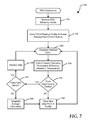
- FIG. 7 is a flow diagram illustrating a method for generating data points at the graph of FIG. 5 according to another embodiment of the present disclosure.
- FIG. 8 is a block diagram illustrating an information handling system in accordance with a specific embodiment of the present disclosure.
- FIGS. 1-8 illustrate techniques for compiling multi-dimensional power conversion efficiency profiles for power supply units (PSUs) at an information handling system.
- a multi-dimensional power conversion efficiency profile provides a mapping between power conversion efficiency of a PSU and two or more operating parameters. For example, PSU efficiency can be affected by a combination of PSU utilization and PSU temperature, or another combination of operating or environmental parameters.
- the compiled multi-dimensional power conversion efficiency profile can be stored and utilized to dynamically regulate engagement of PSUs, and thereby improve power conversion efficiency at the information handling system.
- FIG. 1 shows an information handling system 100 in accordance with at least one embodiment of the present disclosure.
- an information handling system may include any instrumentality or aggregate of instrumentalities operable to compute, classify, process, transmit, receive, retrieve, originate, switch, store, display, manifest, detect, record, reproduce, handle, or utilize any form of information, intelligence, or data for business, scientific, control, entertainment, or other purposes.
- an information handling system may be a personal computer, a PDA, a consumer electronic device, a network server or storage device, a switch router or other network communication device, or any other suitable device and may vary in size, shape, performance, functionality, and price.
- the information handling system may include memory, one or more processing resources such as a central processing unit (CPU) or hardware or software control logic. Additional components of the information handling system may include one or more storage devices, one or more communications ports for communicating with external devices as well as various input and output (I/O) devices, such as a keyboard, a mouse, and a video display. The information handling system may also include one or more buses operable to transmit communications between the various hardware components.
- processing resources such as a central processing unit (CPU) or hardware or software control logic.
- Additional components of the information handling system may include one or more storage devices, one or more communications ports for communicating with external devices as well as various input and output (I/O) devices, such as a keyboard, a mouse, and a video display.
- I/O input and output
- the information handling system may also include one or more buses operable to transmit communications between the various hardware components.
- information handling system 100 is described in an example context of a server chassis with multiple server blades.
- the techniques described herein can be applied in other information handling system contexts that utilize one or multiple power supply units (PSUs) without departing from the scope of the present disclosure.
- PSUs power supply units
- Information handling system 100 includes a plurality of power supply units (PSUs), such as PSUs 10 , 11 , 12 , 13 , 14 , and 15 , server nodes 20 , 21 , 22 , and 23 , and a chassis management control module 30 .
- CMC 30 is configured to monitor and control components of information handling system 100 .
- chassis management control module can activate and deactivate server nodes in response to a power conservation policy, computational requirements, and the like.
- CMC 30 includes a power management control module 40 , which is configured to control operation of PSUs 10 - 15 , and selectively engage and disengage PSUs based on current operating characteristics of information handling system 100 and in accordance with efficiency profiles associated with PSUs 10 - 15 , described in greater detail below.
- CMC 30 includes an input for receiving information from sensors included at a system 100 chassis.
- Power management controller 40 is configured to monitor and engage operation of PSUs 10 - 15 .
- a PSU is engaged when it is actively providing power to a load, such as information handling system 100 .
- a PSU is disengaged when it is not providing power to a load of the information handling system, such as in response to a failure of the PSU, or in response to an action by chassis management control module 30 .
- Information handling system 100 may include other components in addition to those illustrated that also receive power from power delivery module 10 .
- Each PSU of PSUs 10 - 15 has an input to receive electric power via a node labeled “MAINS POWER,” a bidirectional control interface terminal connected to a node labeled “SMBus,” and an output connected to a node labeled “POWER PLANE.”
- Each server node of server nodes 20 - 23 has an input to receive power from node POWER PLANE and a bidirectional control interface terminal connected to node SMBus.
- Chassis management control module 30 is connected to node SMBus. Node SMBus facilitates communication of information between components of information handling system 100 in accordance with an industry-standard SMBus serial interface protocol. For the purpose of example, six PSUs are illustrated at FIG. 1 , however a greater or fewer number of PSUs can be included at information handling system 100 .
- each PSU of PSUs 10 - 15 is compliant with a standard power-management protocol known as PMBus.
- the PMBus protocol is implemented over the SMBus protocol, and enables chassis management control module 30 to program, control, and conduct real-time monitoring of each PSU of PSUs 10 - 15 .
- power management control module 40 is configured to query each PSU of PSUs 10 - 15 to determine an amount of mains power received at the input of a selected PSU via node MAINS POWER (power input), and to determine an amount of power provided to node POWER PLANE at the output of the selected PSU (power output). Based on this information, power management control module 40 can determine a power conversion efficiency of each PSU.
- Module 40 can also determine how much power each PSU is providing in relation to the rated power delivery capability of the PSU, referred to herein as PSU utilization. In addition, module 40 can determine one or more operating parameters, such as a PSU device temperature, PSU cooling-fan exhaust temperature, ambient air temperature, and the like. While the PMBus protocol is used in this example, another standard or proprietary protocol can be used to implement communication between power management control module 40 and each PSU of PSUs 10 - 15 .
- Each server node of server nodes 20 - 23 can include one or more data processing devices, such as a microprocessor or microcomputer, and each data processing device can include one or more processor cores.
- Each server node of server nodes 20 - 23 is operable to access computer-readable medium such as a memory device, which is capable of storing a software program that includes a set of instructions to manipulate at least one processor to perform desired tasks.
- a server node further can include memory devices, other information storage devices, peripheral interface devices, and the like.
- a server node can include one or more interfaces (not shown) to support communications and information transfer with another server node, or with other components of information handling system 100 such as shared information storage devices, peripheral interface devices, and the like (not shown at FIG. 1 ).
- the SMBus interface is an example of one such interface.
- information handling system 100 may include a server rack, and server nodes 20 - 23 may each represent blade servers.
- the amount of power consumed by a respective server node can vary in response to how the corresponding server node is configured, the selection and utilization of associated hardware components, and the type of computations being performed at the server node, amongst other factors.
- chassis management control module 30 can place one or more server nodes into a power-conservation mode when demand for computational resources does not require the operation of all server nodes.
- power management control module 40 can respond to current power demand of information handling system 100 and dynamically shift a peak operating efficiency of selected PSUs, or engage a selected number of PSUs based on information included at PSU efficiency profiles to improve the power conversion efficiency of power delivery module 10 in accordance with one or more embodiments of the present disclosure.
- FIG. 2 is a block diagram illustrating power management control module 40 of FIG. 1 in accordance with a specific embodiment of the present disclosure.
- Power management control module 40 can be implemented using dedicated logic devices, by one or more processors configured to execute a software program, or a combination thereof.
- power management control module 40 is implemented as one or more processors that execute instructions included in one or more software programs.
- power management control module 40 includes a storage component 210 , one or more processors 220 or other data processing devices, and a memory device 230 .
- Storage component 210 is configured to store a power conversion efficiency profile 212 in a data structure such as a file, a table, a linked list, or the like.
- Memory device 230 is configured to store software program and associated process data to implement an efficiency computation software module 232 , interrupt/snapshot module 234 , and multi-dimensional efficiency map module 236 .
- Processor 220 includes a bidirectional control interface connected to node SMBus that is coupled to one or more PSUs 240 , a bidirectional data interface connected to storage component 210 , and a bidirectional data interface connected to memory device 230 .
- Processor 220 is operable to execute software program 232 , 234 , and 236 .
- processor 220 includes an input to receive information from environmental sensors, such a temperature sensors associated with PSUs 10 - 15 .
- Processor 220 may be a device that is dedicated to performing only tasks associated with power management control module 40 , or it may perform additional processing tasks of information handling system 100 .
- PSU 240 includes a data storage device 242 for storing an efficiency profile 244 .
- efficiency profile 244 can provide a three dimensional characterization of operating efficiency of PSU 240 .
- Storage component 210 can include one or more registers included at data processing device 220 , a non-volatile or volatile memory device, or another device operable to store one or more power conversion efficiency profiles, such as power conversion efficiency profile 212 .
- Memory device 230 may include one or more of a hard-disk drive, a random access memory (RAM), a read only memory (ROM), another type of data memory device, or a combination thereof.
- storage component 210 can be implemented using storage resources provided by memory device 230 .
- Power management control module 40 is configured to determine a respective power conversion efficiency profile representing power conversion efficiency characteristics of each corresponding PSU of PSUs 10 - 15 over a range of operating loads and conditions. During operation of information handling system 100 , power management control module 40 can periodically request information from each PSU using the PMBus protocol conducted by node SMBus. For example, management control module 40 can issue a request to PSU 11 inquiring as to an amount of power currently being received by PSU 11 , and a corresponding output power currently being provided by PSU 11 . Based on this information, management control module 40 can calculate a power conversion efficiency of PSU 11 for the current operating load using the equation:
- Power management control module 40 can issue similar requests to each PSU of PSUs 10 - 15 and do so over a range of operating conditions (and an associated range of loads) to compile a power conversion efficiency profile corresponding to each PSU as described in greater detail below.
- a power conversion efficiency profile of a PSU includes a set of data-pairs representative of the power conversion efficiencies of the PSU over a range of output loads or power outputs.
- the power conversion efficiency is calculated and expressed based on a quantity referred to as percent-of-load (POL).
- POL percent-of-load
- Percent-of-load is a fraction, expressed as a percentage, quantifying the power provided by a PSU in relation to a maximum output power capability of the PSU:
- Percent ⁇ - ⁇ of ⁇ - ⁇ load P out P max ⁇ 100 Eq . ⁇ 2
- the variable Pout represents the power provided at the output of the PSU (power output)
- P max represents the specified maximum output power that the PSU is capable of providing. For example, if the maximum output power of a PSU is 1000 watts, and the PSU is currently providing 400 watts of power, the percent-of-load is 40%.
- the power conversion efficiency profile of a PSU can include a respective power conversion efficiency corresponding to percent-of-load values ranging from approximately zero to 100% of percent-of-load.
- the efficiency profile information can be stored in a data structure at storage component 210 .
- PSU efficiency, POL utilization, and PSU temperature measurements can be performed periodically, for example based on a timer.
- the three parameters, efficiency, POL, and temperature provide an individual data point in a three-dimensional efficiency profile.
- a collection of data points corresponding to a range of POL and temperature values can be collected to generate a mapping of PSU efficiency.
- the efficiency profile can be used to estimate PSU efficiency based on a particular POL value and PSU temperature.
- PSU efficiency, POL utilization, and PSU temperature measurements can be performed in response to detecting a change in one or more operational or environmental parameters.
- power management control module 40 can monitor POL utilization of a power supply and generate an interrupt or similar notification each time the POL changes by a specified amount.
- module 40 can monitor PSU temperature and generate an interrupt if the temperature changes by a specified amount.
- module 40 can perform a temperature measurement and efficiency measurement, and thus generate a data point in a multi-dimensional efficiency profile.
- module 40 in response to receiving an interrupt indicating a change in operating temperature, module 40 can perform a POL measurement and efficiency measurement to generate a data point in the efficiency profile.
- Power management control module 40 is further configured to: 1) determine a total amount of power being supplied to information handling system 100 ; 2) determine a power utilization and temperature of each PSU; determine an efficiency of each PSU based on the operating parameters and an efficiency profile; and 4) determine a number of PSUs needed to provide the total amount of power so that each PSU is operating at a substantially optimal efficiency based on an amount of power provided by each PSU.
- the total amount of power to be supplied to information handling system 100 is the total amount of power currently being consumed by all components included at information handling system 100 . Because power consumption can fluctuate in response to varying computational activity of servers 20 - 23 , module 40 can collect periodic load measurements in order to calculate an average, steady state, load at each PSU. Module 40 can periodically repeat this process to maintain optimal efficiency as the total power consumed by system 100 changes over time.
- FIG. 3 is a graph 300 illustrating power a conversion efficiency profile of a PSU included at the information handling system of FIG. 1 in accordance with a specific embodiment of the present disclosure.
- Graph 300 includes a horizontal axis representing percent-of-load, POL, and a vertical axis representing power conversion efficiency, expressed as a percentage.
- Graph 300 includes a power conversion efficiency profile 301 associated with a representative PSU.
- a power conversion efficiency profile associates power conversion efficiency in relationship to a range of percent-of-load values.
- the power conversion efficiency of a PSU can vary over a range of operating load, attaining a maximum efficiency of 90% at a POL of 40%, illustrated by reference 310 . Conversion efficiency decreases for loads below and above the peak efficiency operating condition. It will be appreciated that a power conversion efficiency profile can include fewer, or a greater number of data points.
- FIG. 4 is a graph 400 illustrating another power conversion efficiency profile associated with a PSU included at the information handling system of FIG. 1 in accordance with another embodiment of the present disclosure.
- Graph 400 includes a horizontal axis representing temperature at the PSU, and a vertical axis representing power conversion efficiency, expressed as a percentage.
- Graph 400 includes a power conversion efficiency profile 401 available at a representative PSU.
- a power conversion efficiency profile associates power conversion efficiency in relationship to an operating temperature of the PSU. As illustrated by profile 401 , the power conversion efficiency of a PSU can vary over a range of operating temperature, attaining a maximum efficiency at a temperature of 15° C., illustrated by reference 410 .
- Efficiency profiles 301 and 401 are merely examples of possible PSU behavior, and the shape of the data curves can vary based on numerous circuit and design characteristics. Power supply efficiency is known to be variable based on many factors, including but not limited to power conversion circuitry, such as transformers, transistors, and other discrete components, inlet temperature, input voltage, switching frequency, and the like. One of skill will appreciate that percentage of load and temperature are two examples of operating conditions of a PSU, and that efficiency profiles can be associated with other operating conditions, such as air flow, humidity, barometric pressure, mains voltage, and the like. Moreover, profiles 301 and 401 are independent. For example, profile 301 does not take temperature into consideration, and profile 401 does not take POL into consideration. As disclosed herein, a PSU can include multi-dimensional efficiency profiles mapping PSU efficiency to two or more simultaneous parameters, such as PSU utilization and operating temperature. Accordingly, module 40 can determine PSU efficiency under a combination of operating conditions.
- FIG. 5 is a graph 500 illustrating a multi-dimensional power conversion efficiency profile associated with a PSU included at the information handling system of FIG. 1 in accordance with a specific embodiment of the present disclosure.
- Graph 500 includes a first horizontal axis representing utilization at a PSU, expressed as a POL, a second horizontal axis representing temperature at the PSU, and a vertical axis representing power conversion efficiency, expressed as a percentage.
- Graph 500 includes power conversion efficiency profiles 501 , 502 , 503 , 504 , 505 , 506 , and 507 , each profile corresponding to a respective sub-range of temperature. Therefore, graph 500 provides PSU efficiency at concurrent values of POL and temperature.
- information characterizing profiles 301 , 401 , and 501 can be provided by a manufacturer of a PSU and stored at a memory device included at the PSU.
- the efficiency profile can be accessed by issuing a command provided to the PSU via the PMBus interface.
- a power conversion efficiency profile can be compiled by power management control module 40 over an extended time of operation of information handling system 100 by issuing commands to the PSU to report input and output power at the PSU.
- the data included at a power conversion efficiency profile may be updated periodically, e.g. every thousand operating hours, to maintain the accuracy of the data as the efficiency characteristics of the PSU change over time.
- a single power conversion efficiency profile can be determined and used to represent one or more of multiple PSUs of identical or similar construction. For example, if information handling system 100 includes six similar PSUs, a single power conversion efficiency profile can be prepared and used to represent each of the six PSUs.
- FIG. 6 is a flow diagram illustrating a method 600 for generating data points at graph 500 of FIG. 5 according to a specific embodiment of the present disclosure.
- Method 600 starts at block 601 where a timer determines that a predetermined interval of time has elapsed. For example, interrupt/snapshot module 234 of power management control module 40 can periodically generate a signal indicating a snapshot of current operating conditions should be performed.
- the method continues at block 602 where a present PSU efficiency and present PSU utilization is determined.
- efficiency computation module can determine a current efficiency and POL of a PSU, as described above.
- the efficiency and POL measurements can be configured to provide an average value over a predefined interval of time, such as fifty milliseconds.
- the method 600 proceeds to block 603 where a temperature of the PSU is determined.
- module 40 can receive temperature information from environmental sensors or can request PSU temperature information by issuing a corresponding command to the PSU. Because a temperature of a PSU, such as a fan-exhaust temperature, is unlikely to change very quickly, an instantaneous rather than average measurement can be performed.
- the method continues at block 604 where a multi-dimensional efficiency profile can be updated based on the newly acquired operating data. For example, a data point at graph 500 can be created or updated based on the PSU efficiency corresponding to the substantially simultaneous parameters POL and temperature. Method 500 can be repeated at each PSU included at an information handling system.
- Another technique can be employed to periodically sample operating parameters, such as an interrupt as described above.
- FIG. 7 is a flow diagram illustrating a method 700 for generating data points at graph 500 of FIG. 5 according to another embodiment of the present disclosure.
- Method 700 starts at block 701 where an efficiency profile is retrieved from a PSU.
- power management control module 40 can issue a command over a PMBus to one or more of PSUs 10 - 15 , requesting the PSU to provide one or more efficiency profiles stored therein.
- the efficiency profile can be provided by the original equipment manufacturer of the PSU, or it may be an efficiency profile generated by module 40 that was previous stored at the PSU.
- the profile may include a single-dimensional efficiency profile, such as profiles 301 or 401 , or it may be a multi-dimensional profile, such as profile 501 .
- the method proceeds to block 702 where the PSU efficiency profile is stored at a power management control module.
- the method waits at block 703 until an interrupt is received, or until a predetermined period of time has elapsed.
- the method proceeds to block 704 where current operating parameters are collected.
- module 40 can issue one or more command to a PSU requesting PSU input power, PSU output power, PSU temperature, and the like.
- Operating parameters may also be retrieved from sensors located at each PSU or at one or more locations at system 100 .
- the method proceeds to decision block 705 where it is determined if an efficiency profile already includes the collected parameters.
- a multi-dimensional profile can include PSU POL as a first input parameter and PSU temperature as a second input parameter.
- an efficiency profile does not include a data point associating a particular PSU efficiency to the specific combination of input values, the method proceeds to block 706 where a new data point can be added to the efficiency profile. The method now returns to block 703 where the method waits until another interrupt or snapshot even occurs.
- the method proceeds to decision block 707 where it is determined whether the efficiency corresponding to the particular combination of input parameters matches a value previously associated with those parameter values. If the efficiency is the same as previously associated with that combination of input parameters, the method proceeds to block 708 where the newly collected data point information is discarded, and the method returns to block 703 where the method waits until another interrupt or snapshot even occurs. If, at block 707 , it is determined that the newly measured PSU efficiency associated with the combination of input parameters is different from that previously associated with that particular combination, the method proceeds to block 709 where an average of the previous efficiency value and the new efficiency value can be calculated. The averaging calculation can be weighted based on a total number and value of samples associated with the pair of input parameters, or based on another algorithm. The method proceeds to block 706 where the new data point can be added to the efficiency profile.
- the updated profile can be stored at data storage device 210 of module 40 and/or at data storage device 242 included at a PSU.
- the multi-dimensional efficiency profile can represent PSU efficiency corresponding to a combination of any operating parameters.
- the profile can map PSU efficiency to PSU POL and an ambient temperature of information handling system 100 .
- more than one multi-dimensional efficiency profile can be maintained corresponding to a PSU.
- one profile can map PSU efficiency to PSU POL and temperature given a particular ambient temperature, while another profile can map PSU efficiency to PSU POL and temperature given another ambient temperature.
- a third input parameter may include a value of mains voltage provided the PSUs.
- a PSU may be configured to operate in more than one operating mode, and a unique efficiency profile can be maintained corresponding to each operating mode.
- FIG. 8 illustrates an information handling system 800 including according to a specific embodiment of the present disclosure.
- system 800 can represent each of server nodes 20 - 23 , CMC 30 , or power management control module 40 .
- System 800 includes a processor 802 , a memory 804 , a northbridge/chipset 806 , a PCI bus 808 , a universal serial bus (USB) controller 810 , a USB 812 , a keyboard device controller 814 , a mouse device controller 816 , an ATA bus controller 820 , an ATA bus 822 , a hard drive device controller 824 , a compact disk read only memory (CD ROM) device controller 826 , a video graphics array (VGA) device controller, a serial peripheral interface (SPI) bus 840 , and a non-volatile random access memory (NVRAM) 850 for storing a basic input/output system (BIOS) 852 .
- BIOS basic input/output system
- SMBus 860 provides communication between a motherboard, including the above components, and chassis management components, including power supplies, and the like.
- Information handling system 800 can include additional components and additional busses, not shown for clarity.
- system 800 can include multiple processor cores, one or more network interface controllers (NICs), and the like. While a particular arrangement of bus technologies and interconnections is illustrated for the purpose of example, one of skill will appreciate that the techniques disclosed herein are applicable to other system architectures.
- portions of northbridge/chipset 806 can be integrated within CPU 802 .
- Information handling system 800 can include one or more storage devices that can store machine-executable code, one or more communications ports for communicating with external devices, and various input and output (I/O) devices, such as a keyboard, a mouse, and a video display.
- I/O input and output
- An example of information handling system 800 includes a multi-tenant chassis system where groups of tenants (users) share a common chassis and each of the tenants has a unique set of resources assigned to them.
- the resources can include blade servers of the chassis, input/output (I/O) modules, Peripheral Component Interconnect-Express (PCIe) cards, storage controllers, and the like.
- PCIe Peripheral Component Interconnect-Express
- Information handling system 800 can include a set of instructions that can be executed to cause the information handling system to perform any one or more of the methods or computer based functions disclosed herein.
- the information handling system 800 may operate as a standalone device or may be connected to other computer systems or peripheral devices, such as by a network.
- the information handling system 800 may operate in the capacity of a server or as a client user computer in a server-client user network environment, or as a peer computer system in a peer-to-peer (or distributed) network environment.
- the information handling system 800 can also be implemented as or incorporated into various devices, such as a personal computer (PC), a tablet PC, a set-top box (STB), a personal digital assistant (PDA), a mobile device, a palmtop computer, a laptop computer, a desktop computer, a communications device, a wireless telephone, a land-line telephone, a control system, a camera, a scanner, a facsimile machine, a printer, a pager, a personal trusted device, a web appliance, a network router, switch or bridge, or any other machine capable of executing a set of instructions (sequential or otherwise) that specify actions to be taken by that machine.
- the computer system 100 can be implemented using electronic devices that provide voice, video or data communication.
- the term “system” shall also be taken to include any collection of systems or sub-systems that individually or jointly execute a set, or multiple sets, of instructions to perform one or more computer functions.
- the information handling system 800 can include a disk drive unit and may include a computer-readable medium, not shown in FIG. 8 , in which one or more sets of instructions, such as software, can be embedded. Further, the instructions may embody one or more of the methods or logic as described herein. In a particular embodiment, the instructions may reside completely, or at least partially, within system memory 104 or another memory included at system 800 , and/or within the processor 802 during execution by the information handling system 800 . The system memory 804 and the processor 802 also may include computer-readable media.
- a network interface device (not shown at FIG. 1 ) can provide connectivity to a network, e.g., a wide area network (WAN), a local area network (LAN), or other network.
- dedicated hardware implementations such as application specific integrated circuits, programmable logic arrays and other hardware devices can be constructed to implement one or more of the methods described herein.
- Applications that may include the apparatus and systems of various embodiments can broadly include a variety of electronic and computer systems.
- One or more embodiments described herein may implement functions using two or more specific interconnected hardware modules or devices with related control and data signals that can be communicated between and through the modules, or as portions of an application-specific integrated circuit. Accordingly, the present system encompasses software, firmware, and hardware implementations.
- the methods described herein may be implemented by software programs executable by a computer system.
- implementations can include distributed processing, component/object distributed processing, and parallel processing.
- virtual computer system processing can be constructed to implement one or more of the methods or functionality as described herein.
- the present disclosure contemplates a computer-readable medium that includes instructions or receives and executes instructions responsive to a propagated signal; so that a device connected to a network can communicate voice, video or data over the network. Further, the instructions may be transmitted or received over the network via the network interface device.
- computer-readable medium can include a single medium or multiple media, such as a centralized or distributed database, and/or associated caches and servers that store one or more sets of instructions.
- the term “computer-readable medium” shall also include any medium that is capable of storing, encoding or carrying a set of instructions for execution by a processor or that cause a computer system to perform any one or more of the methods or operations disclosed herein.
- the computer-readable medium can include a solid-state memory such as a memory card or other package that houses one or more non-volatile read-only memories.
- the computer-readable medium can be a random access memory or other volatile re-writable memory.
- the computer-readable medium can include a magneto-optical or optical medium, such as a disk or tapes or other storage device to store information received via carrier wave signals such as a signal communicated over a transmission medium.
- a digital file attachment to an e-mail or other self-contained information archive or set of archives may be considered a distribution medium that is equivalent to a tangible storage medium. Accordingly, the disclosure is considered to include any one or more of a computer-readable medium or a distribution medium and other equivalents and successor media, in which data or instructions may be stored.
Abstract
Description
where the variable Pin represents the power consumed by the PSU (power input), and the variable Pout represents the power provided at the output of the PSU (power output). Power
where the variable Pout represents the power provided at the output of the PSU (power output), and Pmax represents the specified maximum output power that the PSU is capable of providing. For example, if the maximum output power of a PSU is 1000 watts, and the PSU is currently providing 400 watts of power, the percent-of-load is 40%. Thus, the power conversion efficiency profile of a PSU can include a respective power conversion efficiency corresponding to percent-of-load values ranging from approximately zero to 100% of percent-of-load. The efficiency profile information can be stored in a data structure at
Claims (20)
Priority Applications (1)
| Application Number | Priority Date | Filing Date | Title |
|---|---|---|---|
| US14/716,332 US9791902B2 (en) | 2015-05-19 | 2015-05-19 | System and method for providing multi-dimensional power supply efficiency profiles |
Applications Claiming Priority (1)
| Application Number | Priority Date | Filing Date | Title |
|---|---|---|---|
| US14/716,332 US9791902B2 (en) | 2015-05-19 | 2015-05-19 | System and method for providing multi-dimensional power supply efficiency profiles |
Publications (2)
| Publication Number | Publication Date |
|---|---|
| US20160342186A1 US20160342186A1 (en) | 2016-11-24 |
| US9791902B2 true US9791902B2 (en) | 2017-10-17 |
Family
ID=57325413
Family Applications (1)
| Application Number | Title | Priority Date | Filing Date |
|---|---|---|---|
| US14/716,332 Active 2035-06-18 US9791902B2 (en) | 2015-05-19 | 2015-05-19 | System and method for providing multi-dimensional power supply efficiency profiles |
Country Status (1)
| Country | Link |
|---|---|
| US (1) | US9791902B2 (en) |
Cited By (2)
| Publication number | Priority date | Publication date | Assignee | Title |
|---|---|---|---|---|
| US10761583B2 (en) | 2018-09-11 | 2020-09-01 | International Business Machines Corporation | Variation-aware intra-node power shifting among different hardware components |
| US11874717B2 (en) | 2022-02-09 | 2024-01-16 | Microsoft Technology Licensing, Llc | PSU control based on PSU temperature |
Families Citing this family (3)
| Publication number | Priority date | Publication date | Assignee | Title |
|---|---|---|---|---|
| EP3377955B1 (en) * | 2015-11-20 | 2020-08-19 | Galvion Soldier Power, LLC | Power manager with reconfigurable power converting circuits |
| US9857856B2 (en) * | 2015-12-11 | 2018-01-02 | Dell Products, L.P. | System and method for determining power supply unit configurations in an information handling system |
| US11243590B2 (en) * | 2019-09-27 | 2022-02-08 | Dell Products L.P. | Systems and methods for minimizing system hardware throttling due to power supply unit environmental effective capacity |
Citations (33)
| Publication number | Priority date | Publication date | Assignee | Title |
|---|---|---|---|---|
| US5579524A (en) | 1993-10-04 | 1996-11-26 | Elonex I.P. Holdings, Ltd. | Optimized power supply system for computer equipment |
| US6166934A (en) | 1999-06-30 | 2000-12-26 | General Motors Corporation | High efficiency power system with plural parallel DC/DC converters |
| US20040027099A1 (en) | 2000-09-28 | 2004-02-12 | Masashi Fujii | Power supply |
| US20040165407A1 (en) | 2001-01-29 | 2004-08-26 | Hiroyuki Umeda | Power supply apparatus |
| US20040215990A1 (en) | 2003-04-23 | 2004-10-28 | Dell Products L.P. | Energy saving external power adapter |
| US20070079364A1 (en) | 2005-09-30 | 2007-04-05 | Timothy Abels | Directory-secured packages for authentication of software installation |
| US20070083861A1 (en) | 2003-04-18 | 2007-04-12 | Wolfgang Becker | Managing a computer system with blades |
| US20080284510A1 (en) * | 2007-05-18 | 2008-11-20 | Quantance, Inc. | Error driven rf power amplifier control with increased efficiency |
| WO2009007459A2 (en) | 2007-07-11 | 2009-01-15 | Cherokee Europe S.C.A. | Method for power supply control |
| US20090089604A1 (en) * | 2007-09-28 | 2009-04-02 | Malik Randhir S | Apparatus, system, and method for event, time, and failure state recording mechanism in a power supply |
| US7535122B2 (en) | 2006-03-31 | 2009-05-19 | Intel Corporation | Various methods and apparatuses for a multiple input-voltage-level voltage-regulator and a multiple voltage-level DC power supply |
| US20090296432A1 (en) * | 2008-05-27 | 2009-12-03 | Alain Chapuis | Apparatus and method of optimizing power system efficiency using a power loss model |
| US20100037078A1 (en) | 2008-08-05 | 2010-02-11 | Sun Microsystems, Inc. | Technique for regulating power-supply efficiency in a computer system |
| US20100058092A1 (en) * | 2008-08-28 | 2010-03-04 | Sun Microsystems, Inc. | Method for characterizing the health of a computer system power supply |
| US20100064170A1 (en) * | 2008-09-05 | 2010-03-11 | Sun Microsystems, Inc. | Prolonging the remaining useful life of a power supply in a computer system |
| US20100100756A1 (en) | 2008-10-20 | 2010-04-22 | Dell Products L.P. | Power Supply Wear Leveling in a Multiple-PSU Information Handling System |
| US20100107159A1 (en) | 2008-10-29 | 2010-04-29 | Dell Products L.P. | Virtual Machine Scheduling Methods and Systems |
| US7720637B2 (en) | 2007-11-07 | 2010-05-18 | Dell Products L.P. | Systems and methods for efficient utilization of power sources in a redundant configuration |
| US20100146039A1 (en) | 2008-12-08 | 2010-06-10 | Dell Products L.P. | System and Method for Providing Access to a Shared System Image |
| US20100277000A1 (en) | 2009-04-30 | 2010-11-04 | Daniel Humphrey | Efficiency Power Supply System Having A Redundant Supply That Remains Online While Sourcing No Current |
| US7831843B2 (en) | 2006-09-26 | 2010-11-09 | Dell Products L.P. | Apparatus and methods for managing power in an information handling system |
| US20100319153A1 (en) | 2009-06-19 | 2010-12-23 | Ming Yi Technology Co., Ltd. | Back scrubber |
| US20100332873A1 (en) * | 2009-06-30 | 2010-12-30 | Ashish Munjal | Power Supply Engagement and Method Therefor |
| US20110115447A1 (en) * | 2009-11-19 | 2011-05-19 | Asustek Computer Inc. | Multiphase power supply device and current adjusting method thereof |
| US8132034B2 (en) | 2008-08-28 | 2012-03-06 | Dell Products L.P. | System and method for managing information handling system power supply capacity utilization based on load sharing power loss |
| US20120066519A1 (en) * | 2010-09-09 | 2012-03-15 | International Business Machines Corporation | Data center power conversion efficiency management |
| US20120281433A1 (en) * | 2010-11-02 | 2012-11-08 | Mitsubishi Electric Corporation | Power supply apparatus and controller |
| US20130027009A1 (en) * | 2011-07-29 | 2013-01-31 | Primarion, Inc. | Switching Regulator with Increased Light Load Efficiency |
| US20130093251A1 (en) * | 2011-10-14 | 2013-04-18 | Fujitsu Limited | Regulator device |
| US8566427B2 (en) | 2009-01-30 | 2013-10-22 | Dell Products L.P. | Desktop environment solutions methods and systems |
| US8726269B2 (en) | 2009-04-14 | 2014-05-13 | Dell Products L.P. | Method to enable application sharing on embedded hypervisors by installing only application context |
| US20140181544A1 (en) | 2012-12-21 | 2014-06-26 | Dell Products L.P. | Reducing Power Consumption of a Redundant Power System Utilizing Sleep Power Consumption Considerations for Power Supply Units Within the Redundant Power System |
| US9413220B2 (en) * | 2012-08-13 | 2016-08-09 | Northrop Grumman Systems Corporation | Power supply systems and methods |
-
2015
- 2015-05-19 US US14/716,332 patent/US9791902B2/en active Active
Patent Citations (35)
| Publication number | Priority date | Publication date | Assignee | Title |
|---|---|---|---|---|
| US5579524A (en) | 1993-10-04 | 1996-11-26 | Elonex I.P. Holdings, Ltd. | Optimized power supply system for computer equipment |
| US6166934A (en) | 1999-06-30 | 2000-12-26 | General Motors Corporation | High efficiency power system with plural parallel DC/DC converters |
| US20040027099A1 (en) | 2000-09-28 | 2004-02-12 | Masashi Fujii | Power supply |
| US20040165407A1 (en) | 2001-01-29 | 2004-08-26 | Hiroyuki Umeda | Power supply apparatus |
| US20070083861A1 (en) | 2003-04-18 | 2007-04-12 | Wolfgang Becker | Managing a computer system with blades |
| US20040215990A1 (en) | 2003-04-23 | 2004-10-28 | Dell Products L.P. | Energy saving external power adapter |
| US20070079364A1 (en) | 2005-09-30 | 2007-04-05 | Timothy Abels | Directory-secured packages for authentication of software installation |
| US7535122B2 (en) | 2006-03-31 | 2009-05-19 | Intel Corporation | Various methods and apparatuses for a multiple input-voltage-level voltage-regulator and a multiple voltage-level DC power supply |
| US7831843B2 (en) | 2006-09-26 | 2010-11-09 | Dell Products L.P. | Apparatus and methods for managing power in an information handling system |
| US20080284510A1 (en) * | 2007-05-18 | 2008-11-20 | Quantance, Inc. | Error driven rf power amplifier control with increased efficiency |
| WO2009007459A2 (en) | 2007-07-11 | 2009-01-15 | Cherokee Europe S.C.A. | Method for power supply control |
| US20090089604A1 (en) * | 2007-09-28 | 2009-04-02 | Malik Randhir S | Apparatus, system, and method for event, time, and failure state recording mechanism in a power supply |
| US7720637B2 (en) | 2007-11-07 | 2010-05-18 | Dell Products L.P. | Systems and methods for efficient utilization of power sources in a redundant configuration |
| US20090296432A1 (en) * | 2008-05-27 | 2009-12-03 | Alain Chapuis | Apparatus and method of optimizing power system efficiency using a power loss model |
| US20100037078A1 (en) | 2008-08-05 | 2010-02-11 | Sun Microsystems, Inc. | Technique for regulating power-supply efficiency in a computer system |
| US8132034B2 (en) | 2008-08-28 | 2012-03-06 | Dell Products L.P. | System and method for managing information handling system power supply capacity utilization based on load sharing power loss |
| US20100058092A1 (en) * | 2008-08-28 | 2010-03-04 | Sun Microsystems, Inc. | Method for characterizing the health of a computer system power supply |
| US8499178B2 (en) | 2008-08-28 | 2013-07-30 | Dell Products L.P. | System and method for managing information handling system power supply capacity utilization based on load sharing power loss |
| US20100064170A1 (en) * | 2008-09-05 | 2010-03-11 | Sun Microsystems, Inc. | Prolonging the remaining useful life of a power supply in a computer system |
| US20100100756A1 (en) | 2008-10-20 | 2010-04-22 | Dell Products L.P. | Power Supply Wear Leveling in a Multiple-PSU Information Handling System |
| US20100107159A1 (en) | 2008-10-29 | 2010-04-29 | Dell Products L.P. | Virtual Machine Scheduling Methods and Systems |
| US20100146039A1 (en) | 2008-12-08 | 2010-06-10 | Dell Products L.P. | System and Method for Providing Access to a Shared System Image |
| US8566427B2 (en) | 2009-01-30 | 2013-10-22 | Dell Products L.P. | Desktop environment solutions methods and systems |
| US8726269B2 (en) | 2009-04-14 | 2014-05-13 | Dell Products L.P. | Method to enable application sharing on embedded hypervisors by installing only application context |
| US20100277000A1 (en) | 2009-04-30 | 2010-11-04 | Daniel Humphrey | Efficiency Power Supply System Having A Redundant Supply That Remains Online While Sourcing No Current |
| US20100319153A1 (en) | 2009-06-19 | 2010-12-23 | Ming Yi Technology Co., Ltd. | Back scrubber |
| US20100332873A1 (en) * | 2009-06-30 | 2010-12-30 | Ashish Munjal | Power Supply Engagement and Method Therefor |
| US8918656B2 (en) | 2009-06-30 | 2014-12-23 | Dell Products, Lp | Power supply engagement and method therefor |
| US20110115447A1 (en) * | 2009-11-19 | 2011-05-19 | Asustek Computer Inc. | Multiphase power supply device and current adjusting method thereof |
| US20120066519A1 (en) * | 2010-09-09 | 2012-03-15 | International Business Machines Corporation | Data center power conversion efficiency management |
| US20120281433A1 (en) * | 2010-11-02 | 2012-11-08 | Mitsubishi Electric Corporation | Power supply apparatus and controller |
| US20130027009A1 (en) * | 2011-07-29 | 2013-01-31 | Primarion, Inc. | Switching Regulator with Increased Light Load Efficiency |
| US20130093251A1 (en) * | 2011-10-14 | 2013-04-18 | Fujitsu Limited | Regulator device |
| US9413220B2 (en) * | 2012-08-13 | 2016-08-09 | Northrop Grumman Systems Corporation | Power supply systems and methods |
| US20140181544A1 (en) | 2012-12-21 | 2014-06-26 | Dell Products L.P. | Reducing Power Consumption of a Redundant Power System Utilizing Sleep Power Consumption Considerations for Power Supply Units Within the Redundant Power System |
Cited By (2)
| Publication number | Priority date | Publication date | Assignee | Title |
|---|---|---|---|---|
| US10761583B2 (en) | 2018-09-11 | 2020-09-01 | International Business Machines Corporation | Variation-aware intra-node power shifting among different hardware components |
| US11874717B2 (en) | 2022-02-09 | 2024-01-16 | Microsoft Technology Licensing, Llc | PSU control based on PSU temperature |
Also Published As
| Publication number | Publication date |
|---|---|
| US20160342186A1 (en) | 2016-11-24 |
Similar Documents
| Publication | Publication Date | Title |
|---|---|---|
| US20160313777A1 (en) | System and Method for Dynamically Adjusting Power Supply Efficiency | |
| US9436257B2 (en) | Power supply engagement and method therefor | |
| US9791902B2 (en) | System and method for providing multi-dimensional power supply efficiency profiles | |
| US9395790B2 (en) | Power management system | |
| US10877533B2 (en) | Energy efficient workload placement management using predetermined server efficiency data | |
| US8639962B2 (en) | Power profiling application for managing power allocation in an information handling system | |
| US8390148B2 (en) | Systems and methods for power supply wear leveling in a blade server chassis | |
| US7975156B2 (en) | System and method for adapting a power usage of a server during a data center cooling failure | |
| US10241554B2 (en) | System and method for increasing group level power supply unit efficiency | |
| US8468380B2 (en) | Power consumption monitor and method therefor | |
| US7349828B1 (en) | Estimating an electronic device condition | |
| US8862905B2 (en) | Collecting and analysing telemetry data to dynamically cap power and temperature of a computer system by specifying virtual duty cycles for processes executing on a processor | |
| US10528119B2 (en) | Dynamic power routing to hardware accelerators | |
| US9990467B2 (en) | Electronic system with health monitoring mechanism and method of operation thereof | |
| US10114438B2 (en) | Dynamic power budgeting in a chassis | |
| US9002668B2 (en) | Discovering an equipment power connection relationship | |
| US20160282928A1 (en) | Systems and methods for non-uniform power supply unit load sharing | |
| US11442527B2 (en) | System and method for turning off a display device based on energy usage | |
| US11755090B2 (en) | Real-time communication of power supply unit power loading status | |
| US11157056B2 (en) | System and method for monitoring a maximum load based on an aggregate load profile of a system | |
| US11592891B2 (en) | System and method for diagnosing resistive shorts in an information handling system | |
| KR20160014251A (en) | Apparatus and method for analyzing power efficiency |
Legal Events
| Date | Code | Title | Description |
|---|---|---|---|
| AS | Assignment |
Owner name: DELL PRODUCTS, LP, TEXAS Free format text: ASSIGNMENT OF ASSIGNORS INTEREST;ASSIGNORS:RAGUPATHI, DINESH K.;MUNJAL, ASHISH;ARCHER, THOMAS F.;AND OTHERS;SIGNING DATES FROM 20150507 TO 20150518;REEL/FRAME:035720/0171 |
|
| AS | Assignment |
Owner name: THE BANK OF NEW YORK MELLON TRUST COMPANY, N.A., AS NOTES COLLATERAL AGENT, TEXAS Free format text: SUPPLEMENT TO PATENT SECURITY AGREEMENT (NOTES);ASSIGNORS:DELL PRODUCTS L.P.;DELL SOFTWARE INC.;WYSE TECHNOLOGY L.L.C.;REEL/FRAME:036502/0291 Effective date: 20150825 Owner name: BANK OF AMERICA, N.A., AS COLLATERAL AGENT, NORTH CAROLINA Free format text: SUPPLEMENT TO PATENT SECURITY AGREEMENT (TERM LOAN);ASSIGNORS:DELL PRODUCTS L.P.;DELL SOFTWARE INC.;WYSE TECHNOLOGY L.L.C.;REEL/FRAME:036502/0237 Effective date: 20150825 Owner name: BANK OF AMERICA, N.A., AS ADMINISTRATIVE AGENT, NORTH CAROLINA Free format text: SUPPLEMENT TO PATENT SECURITY AGREEMENT (ABL);ASSIGNORS:DELL PRODUCTS L.P.;DELL SOFTWARE INC.;WYSE TECHNOLOGY, L.L.C.;REEL/FRAME:036502/0206 Effective date: 20150825 Owner name: BANK OF AMERICA, N.A., AS ADMINISTRATIVE AGENT, NO Free format text: SUPPLEMENT TO PATENT SECURITY AGREEMENT (ABL);ASSIGNORS:DELL PRODUCTS L.P.;DELL SOFTWARE INC.;WYSE TECHNOLOGY, L.L.C.;REEL/FRAME:036502/0206 Effective date: 20150825 Owner name: BANK OF AMERICA, N.A., AS COLLATERAL AGENT, NORTH Free format text: SUPPLEMENT TO PATENT SECURITY AGREEMENT (TERM LOAN);ASSIGNORS:DELL PRODUCTS L.P.;DELL SOFTWARE INC.;WYSE TECHNOLOGY L.L.C.;REEL/FRAME:036502/0237 Effective date: 20150825 Owner name: THE BANK OF NEW YORK MELLON TRUST COMPANY, N.A., A Free format text: SUPPLEMENT TO PATENT SECURITY AGREEMENT (NOTES);ASSIGNORS:DELL PRODUCTS L.P.;DELL SOFTWARE INC.;WYSE TECHNOLOGY L.L.C.;REEL/FRAME:036502/0291 Effective date: 20150825 |
|
| AS | Assignment |
Owner name: WYSE TECHNOLOGY L.L.C., CALIFORNIA Free format text: RELEASE OF REEL 036502 FRAME 0206 (ABL);ASSIGNOR:BANK OF AMERICA, N.A., AS ADMINISTRATIVE AGENT;REEL/FRAME:040017/0204 Effective date: 20160907 Owner name: DELL SOFTWARE INC., CALIFORNIA Free format text: RELEASE OF REEL 036502 FRAME 0206 (ABL);ASSIGNOR:BANK OF AMERICA, N.A., AS ADMINISTRATIVE AGENT;REEL/FRAME:040017/0204 Effective date: 20160907 Owner name: DELL PRODUCTS L.P., TEXAS Free format text: RELEASE OF REEL 036502 FRAME 0206 (ABL);ASSIGNOR:BANK OF AMERICA, N.A., AS ADMINISTRATIVE AGENT;REEL/FRAME:040017/0204 Effective date: 20160907 |
|
| AS | Assignment |
Owner name: WYSE TECHNOLOGY L.L.C., CALIFORNIA Free format text: RELEASE OF REEL 036502 FRAME 0291 (NOTE);ASSIGNOR:BANK OF NEW YORK MELLON TRUST COMPANY, N.A., AS COLLATERAL AGENT;REEL/FRAME:040027/0637 Effective date: 20160907 Owner name: WYSE TECHNOLOGY L.L.C., CALIFORNIA Free format text: RELEASE OF REEL 036502 FRAME 0237 (TL);ASSIGNOR:BANK OF AMERICA, N.A., AS COLLATERAL AGENT;REEL/FRAME:040028/0088 Effective date: 20160907 Owner name: DELL PRODUCTS L.P., TEXAS Free format text: RELEASE OF REEL 036502 FRAME 0237 (TL);ASSIGNOR:BANK OF AMERICA, N.A., AS COLLATERAL AGENT;REEL/FRAME:040028/0088 Effective date: 20160907 Owner name: DELL SOFTWARE INC., CALIFORNIA Free format text: RELEASE OF REEL 036502 FRAME 0291 (NOTE);ASSIGNOR:BANK OF NEW YORK MELLON TRUST COMPANY, N.A., AS COLLATERAL AGENT;REEL/FRAME:040027/0637 Effective date: 20160907 Owner name: DELL PRODUCTS L.P., TEXAS Free format text: RELEASE OF REEL 036502 FRAME 0291 (NOTE);ASSIGNOR:BANK OF NEW YORK MELLON TRUST COMPANY, N.A., AS COLLATERAL AGENT;REEL/FRAME:040027/0637 Effective date: 20160907 Owner name: DELL SOFTWARE INC., CALIFORNIA Free format text: RELEASE OF REEL 036502 FRAME 0237 (TL);ASSIGNOR:BANK OF AMERICA, N.A., AS COLLATERAL AGENT;REEL/FRAME:040028/0088 Effective date: 20160907 |
|
| AS | Assignment |
Owner name: CREDIT SUISSE AG, CAYMAN ISLANDS BRANCH, AS COLLATERAL AGENT, NORTH CAROLINA Free format text: SECURITY AGREEMENT;ASSIGNORS:ASAP SOFTWARE EXPRESS, INC.;AVENTAIL LLC;CREDANT TECHNOLOGIES, INC.;AND OTHERS;REEL/FRAME:040134/0001 Effective date: 20160907 Owner name: THE BANK OF NEW YORK MELLON TRUST COMPANY, N.A., AS NOTES COLLATERAL AGENT, TEXAS Free format text: SECURITY AGREEMENT;ASSIGNORS:ASAP SOFTWARE EXPRESS, INC.;AVENTAIL LLC;CREDANT TECHNOLOGIES, INC.;AND OTHERS;REEL/FRAME:040136/0001 Effective date: 20160907 Owner name: THE BANK OF NEW YORK MELLON TRUST COMPANY, N.A., A Free format text: SECURITY AGREEMENT;ASSIGNORS:ASAP SOFTWARE EXPRESS, INC.;AVENTAIL LLC;CREDANT TECHNOLOGIES, INC.;AND OTHERS;REEL/FRAME:040136/0001 Effective date: 20160907 Owner name: CREDIT SUISSE AG, CAYMAN ISLANDS BRANCH, AS COLLAT Free format text: SECURITY AGREEMENT;ASSIGNORS:ASAP SOFTWARE EXPRESS, INC.;AVENTAIL LLC;CREDANT TECHNOLOGIES, INC.;AND OTHERS;REEL/FRAME:040134/0001 Effective date: 20160907 |
|
| STCF | Information on status: patent grant |
Free format text: PATENTED CASE |
|
| AS | Assignment |
Owner name: THE BANK OF NEW YORK MELLON TRUST COMPANY, N.A., T Free format text: SECURITY AGREEMENT;ASSIGNORS:CREDANT TECHNOLOGIES, INC.;DELL INTERNATIONAL L.L.C.;DELL MARKETING L.P.;AND OTHERS;REEL/FRAME:049452/0223 Effective date: 20190320 Owner name: THE BANK OF NEW YORK MELLON TRUST COMPANY, N.A., TEXAS Free format text: SECURITY AGREEMENT;ASSIGNORS:CREDANT TECHNOLOGIES, INC.;DELL INTERNATIONAL L.L.C.;DELL MARKETING L.P.;AND OTHERS;REEL/FRAME:049452/0223 Effective date: 20190320 |
|
| AS | Assignment |
Owner name: THE BANK OF NEW YORK MELLON TRUST COMPANY, N.A., TEXAS Free format text: SECURITY AGREEMENT;ASSIGNORS:CREDANT TECHNOLOGIES INC.;DELL INTERNATIONAL L.L.C.;DELL MARKETING L.P.;AND OTHERS;REEL/FRAME:053546/0001 Effective date: 20200409 |
|
| MAFP | Maintenance fee payment |
Free format text: PAYMENT OF MAINTENANCE FEE, 4TH YEAR, LARGE ENTITY (ORIGINAL EVENT CODE: M1551); ENTITY STATUS OF PATENT OWNER: LARGE ENTITY Year of fee payment: 4 |
|
| AS | Assignment |
Owner name: WYSE TECHNOLOGY L.L.C., CALIFORNIA Free format text: RELEASE BY SECURED PARTY;ASSIGNOR:CREDIT SUISSE AG, CAYMAN ISLANDS BRANCH;REEL/FRAME:058216/0001 Effective date: 20211101 Owner name: SCALEIO LLC, MASSACHUSETTS Free format text: RELEASE BY SECURED PARTY;ASSIGNOR:CREDIT SUISSE AG, CAYMAN ISLANDS BRANCH;REEL/FRAME:058216/0001 Effective date: 20211101 Owner name: MOZY, INC., WASHINGTON Free format text: RELEASE BY SECURED PARTY;ASSIGNOR:CREDIT SUISSE AG, CAYMAN ISLANDS BRANCH;REEL/FRAME:058216/0001 Effective date: 20211101 Owner name: MAGINATICS LLC, CALIFORNIA Free format text: RELEASE BY SECURED PARTY;ASSIGNOR:CREDIT SUISSE AG, CAYMAN ISLANDS BRANCH;REEL/FRAME:058216/0001 Effective date: 20211101 Owner name: FORCE10 NETWORKS, INC., CALIFORNIA Free format text: RELEASE BY SECURED PARTY;ASSIGNOR:CREDIT SUISSE AG, CAYMAN ISLANDS BRANCH;REEL/FRAME:058216/0001 Effective date: 20211101 Owner name: EMC IP HOLDING COMPANY LLC, TEXAS Free format text: RELEASE BY SECURED PARTY;ASSIGNOR:CREDIT SUISSE AG, CAYMAN ISLANDS BRANCH;REEL/FRAME:058216/0001 Effective date: 20211101 Owner name: EMC CORPORATION, MASSACHUSETTS Free format text: RELEASE BY SECURED PARTY;ASSIGNOR:CREDIT SUISSE AG, CAYMAN ISLANDS BRANCH;REEL/FRAME:058216/0001 Effective date: 20211101 Owner name: DELL SYSTEMS CORPORATION, TEXAS Free format text: RELEASE BY SECURED PARTY;ASSIGNOR:CREDIT SUISSE AG, CAYMAN ISLANDS BRANCH;REEL/FRAME:058216/0001 Effective date: 20211101 Owner name: DELL SOFTWARE INC., CALIFORNIA Free format text: RELEASE BY SECURED PARTY;ASSIGNOR:CREDIT SUISSE AG, CAYMAN ISLANDS BRANCH;REEL/FRAME:058216/0001 Effective date: 20211101 Owner name: DELL PRODUCTS L.P., TEXAS Free format text: RELEASE BY SECURED PARTY;ASSIGNOR:CREDIT SUISSE AG, CAYMAN ISLANDS BRANCH;REEL/FRAME:058216/0001 Effective date: 20211101 Owner name: DELL MARKETING L.P., TEXAS Free format text: RELEASE BY SECURED PARTY;ASSIGNOR:CREDIT SUISSE AG, CAYMAN ISLANDS BRANCH;REEL/FRAME:058216/0001 Effective date: 20211101 Owner name: DELL INTERNATIONAL, L.L.C., TEXAS Free format text: RELEASE BY SECURED PARTY;ASSIGNOR:CREDIT SUISSE AG, CAYMAN ISLANDS BRANCH;REEL/FRAME:058216/0001 Effective date: 20211101 Owner name: DELL USA L.P., TEXAS Free format text: RELEASE BY SECURED PARTY;ASSIGNOR:CREDIT SUISSE AG, CAYMAN ISLANDS BRANCH;REEL/FRAME:058216/0001 Effective date: 20211101 Owner name: CREDANT TECHNOLOGIES, INC., TEXAS Free format text: RELEASE BY SECURED PARTY;ASSIGNOR:CREDIT SUISSE AG, CAYMAN ISLANDS BRANCH;REEL/FRAME:058216/0001 Effective date: 20211101 Owner name: AVENTAIL LLC, CALIFORNIA Free format text: RELEASE BY SECURED PARTY;ASSIGNOR:CREDIT SUISSE AG, CAYMAN ISLANDS BRANCH;REEL/FRAME:058216/0001 Effective date: 20211101 Owner name: ASAP SOFTWARE EXPRESS, INC., ILLINOIS Free format text: RELEASE BY SECURED PARTY;ASSIGNOR:CREDIT SUISSE AG, CAYMAN ISLANDS BRANCH;REEL/FRAME:058216/0001 Effective date: 20211101 |
|
| AS | Assignment |
Owner name: SCALEIO LLC, MASSACHUSETTS Free format text: RELEASE OF SECURITY INTEREST IN PATENTS PREVIOUSLY RECORDED AT REEL/FRAME (040136/0001);ASSIGNOR:THE BANK OF NEW YORK MELLON TRUST COMPANY, N.A., AS NOTES COLLATERAL AGENT;REEL/FRAME:061324/0001 Effective date: 20220329 Owner name: EMC IP HOLDING COMPANY LLC (ON BEHALF OF ITSELF AND AS SUCCESSOR-IN-INTEREST TO MOZY, INC.), TEXAS Free format text: RELEASE OF SECURITY INTEREST IN PATENTS PREVIOUSLY RECORDED AT REEL/FRAME (040136/0001);ASSIGNOR:THE BANK OF NEW YORK MELLON TRUST COMPANY, N.A., AS NOTES COLLATERAL AGENT;REEL/FRAME:061324/0001 Effective date: 20220329 Owner name: EMC CORPORATION (ON BEHALF OF ITSELF AND AS SUCCESSOR-IN-INTEREST TO MAGINATICS LLC), MASSACHUSETTS Free format text: RELEASE OF SECURITY INTEREST IN PATENTS PREVIOUSLY RECORDED AT REEL/FRAME (040136/0001);ASSIGNOR:THE BANK OF NEW YORK MELLON TRUST COMPANY, N.A., AS NOTES COLLATERAL AGENT;REEL/FRAME:061324/0001 Effective date: 20220329 Owner name: DELL MARKETING CORPORATION (SUCCESSOR-IN-INTEREST TO FORCE10 NETWORKS, INC. AND WYSE TECHNOLOGY L.L.C.), TEXAS Free format text: RELEASE OF SECURITY INTEREST IN PATENTS PREVIOUSLY RECORDED AT REEL/FRAME (040136/0001);ASSIGNOR:THE BANK OF NEW YORK MELLON TRUST COMPANY, N.A., AS NOTES COLLATERAL AGENT;REEL/FRAME:061324/0001 Effective date: 20220329 Owner name: DELL PRODUCTS L.P., TEXAS Free format text: RELEASE OF SECURITY INTEREST IN PATENTS PREVIOUSLY RECORDED AT REEL/FRAME (040136/0001);ASSIGNOR:THE BANK OF NEW YORK MELLON TRUST COMPANY, N.A., AS NOTES COLLATERAL AGENT;REEL/FRAME:061324/0001 Effective date: 20220329 Owner name: DELL INTERNATIONAL L.L.C., TEXAS Free format text: RELEASE OF SECURITY INTEREST IN PATENTS PREVIOUSLY RECORDED AT REEL/FRAME (040136/0001);ASSIGNOR:THE BANK OF NEW YORK MELLON TRUST COMPANY, N.A., AS NOTES COLLATERAL AGENT;REEL/FRAME:061324/0001 Effective date: 20220329 Owner name: DELL USA L.P., TEXAS Free format text: RELEASE OF SECURITY INTEREST IN PATENTS PREVIOUSLY RECORDED AT REEL/FRAME (040136/0001);ASSIGNOR:THE BANK OF NEW YORK MELLON TRUST COMPANY, N.A., AS NOTES COLLATERAL AGENT;REEL/FRAME:061324/0001 Effective date: 20220329 Owner name: DELL MARKETING L.P. (ON BEHALF OF ITSELF AND AS SUCCESSOR-IN-INTEREST TO CREDANT TECHNOLOGIES, INC.), TEXAS Free format text: RELEASE OF SECURITY INTEREST IN PATENTS PREVIOUSLY RECORDED AT REEL/FRAME (040136/0001);ASSIGNOR:THE BANK OF NEW YORK MELLON TRUST COMPANY, N.A., AS NOTES COLLATERAL AGENT;REEL/FRAME:061324/0001 Effective date: 20220329 Owner name: DELL MARKETING CORPORATION (SUCCESSOR-IN-INTEREST TO ASAP SOFTWARE EXPRESS, INC.), TEXAS Free format text: RELEASE OF SECURITY INTEREST IN PATENTS PREVIOUSLY RECORDED AT REEL/FRAME (040136/0001);ASSIGNOR:THE BANK OF NEW YORK MELLON TRUST COMPANY, N.A., AS NOTES COLLATERAL AGENT;REEL/FRAME:061324/0001 Effective date: 20220329 |
|
| AS | Assignment |
Owner name: SCALEIO LLC, MASSACHUSETTS Free format text: RELEASE OF SECURITY INTEREST IN PATENTS PREVIOUSLY RECORDED AT REEL/FRAME (045455/0001);ASSIGNOR:THE BANK OF NEW YORK MELLON TRUST COMPANY, N.A., AS NOTES COLLATERAL AGENT;REEL/FRAME:061753/0001 Effective date: 20220329 Owner name: EMC IP HOLDING COMPANY LLC (ON BEHALF OF ITSELF AND AS SUCCESSOR-IN-INTEREST TO MOZY, INC.), TEXAS Free format text: RELEASE OF SECURITY INTEREST IN PATENTS PREVIOUSLY RECORDED AT REEL/FRAME (045455/0001);ASSIGNOR:THE BANK OF NEW YORK MELLON TRUST COMPANY, N.A., AS NOTES COLLATERAL AGENT;REEL/FRAME:061753/0001 Effective date: 20220329 Owner name: EMC CORPORATION (ON BEHALF OF ITSELF AND AS SUCCESSOR-IN-INTEREST TO MAGINATICS LLC), MASSACHUSETTS Free format text: RELEASE OF SECURITY INTEREST IN PATENTS PREVIOUSLY RECORDED AT REEL/FRAME (045455/0001);ASSIGNOR:THE BANK OF NEW YORK MELLON TRUST COMPANY, N.A., AS NOTES COLLATERAL AGENT;REEL/FRAME:061753/0001 Effective date: 20220329 Owner name: DELL MARKETING CORPORATION (SUCCESSOR-IN-INTEREST TO FORCE10 NETWORKS, INC. AND WYSE TECHNOLOGY L.L.C.), TEXAS Free format text: RELEASE OF SECURITY INTEREST IN PATENTS PREVIOUSLY RECORDED AT REEL/FRAME (045455/0001);ASSIGNOR:THE BANK OF NEW YORK MELLON TRUST COMPANY, N.A., AS NOTES COLLATERAL AGENT;REEL/FRAME:061753/0001 Effective date: 20220329 Owner name: DELL PRODUCTS L.P., TEXAS Free format text: RELEASE OF SECURITY INTEREST IN PATENTS PREVIOUSLY RECORDED AT REEL/FRAME (045455/0001);ASSIGNOR:THE BANK OF NEW YORK MELLON TRUST COMPANY, N.A., AS NOTES COLLATERAL AGENT;REEL/FRAME:061753/0001 Effective date: 20220329 Owner name: DELL INTERNATIONAL L.L.C., TEXAS Free format text: RELEASE OF SECURITY INTEREST IN PATENTS PREVIOUSLY RECORDED AT REEL/FRAME (045455/0001);ASSIGNOR:THE BANK OF NEW YORK MELLON TRUST COMPANY, N.A., AS NOTES COLLATERAL AGENT;REEL/FRAME:061753/0001 Effective date: 20220329 Owner name: DELL USA L.P., TEXAS Free format text: RELEASE OF SECURITY INTEREST IN PATENTS PREVIOUSLY RECORDED AT REEL/FRAME (045455/0001);ASSIGNOR:THE BANK OF NEW YORK MELLON TRUST COMPANY, N.A., AS NOTES COLLATERAL AGENT;REEL/FRAME:061753/0001 Effective date: 20220329 Owner name: DELL MARKETING L.P. (ON BEHALF OF ITSELF AND AS SUCCESSOR-IN-INTEREST TO CREDANT TECHNOLOGIES, INC.), TEXAS Free format text: RELEASE OF SECURITY INTEREST IN PATENTS PREVIOUSLY RECORDED AT REEL/FRAME (045455/0001);ASSIGNOR:THE BANK OF NEW YORK MELLON TRUST COMPANY, N.A., AS NOTES COLLATERAL AGENT;REEL/FRAME:061753/0001 Effective date: 20220329 Owner name: DELL MARKETING CORPORATION (SUCCESSOR-IN-INTEREST TO ASAP SOFTWARE EXPRESS, INC.), TEXAS Free format text: RELEASE OF SECURITY INTEREST IN PATENTS PREVIOUSLY RECORDED AT REEL/FRAME (045455/0001);ASSIGNOR:THE BANK OF NEW YORK MELLON TRUST COMPANY, N.A., AS NOTES COLLATERAL AGENT;REEL/FRAME:061753/0001 Effective date: 20220329 |