EP1431659B1 - Connection system for pipes having a non linear continuous diameter end - Google Patents
Connection system for pipes having a non linear continuous diameter end Download PDFInfo
- Publication number
- EP1431659B1 EP1431659B1 EP03027803A EP03027803A EP1431659B1 EP 1431659 B1 EP1431659 B1 EP 1431659B1 EP 03027803 A EP03027803 A EP 03027803A EP 03027803 A EP03027803 A EP 03027803A EP 1431659 B1 EP1431659 B1 EP 1431659B1
- Authority
- EP
- European Patent Office
- Prior art keywords
- section
- linear continuous
- plug
- pipe
- continuous section
- Prior art date
- Legal status (The legal status is an assumption and is not a legal conclusion. Google has not performed a legal analysis and makes no representation as to the accuracy of the status listed.)
- Expired - Lifetime
Links
- 238000007789 sealing Methods 0.000 claims description 14
- 238000004378 air conditioning Methods 0.000 claims description 5
- 238000005516 engineering process Methods 0.000 claims description 4
- 238000009423 ventilation Methods 0.000 claims description 4
- 229910000831 Steel Inorganic materials 0.000 claims description 2
- 229910001220 stainless steel Inorganic materials 0.000 claims description 2
- 239000010935 stainless steel Substances 0.000 claims description 2
- 239000010959 steel Substances 0.000 claims description 2
- 230000009977 dual effect Effects 0.000 claims 5
- 239000007789 gas Substances 0.000 description 11
- 238000010276 construction Methods 0.000 description 7
- QAOWNCQODCNURD-UHFFFAOYSA-N Sulfuric acid Chemical compound OS(O)(=O)=O QAOWNCQODCNURD-UHFFFAOYSA-N 0.000 description 4
- 230000004858 capillary barrier Effects 0.000 description 4
- 239000000919 ceramic Substances 0.000 description 4
- 239000011810 insulating material Substances 0.000 description 4
- 239000011324 bead Substances 0.000 description 3
- 238000002485 combustion reaction Methods 0.000 description 3
- 239000012774 insulation material Substances 0.000 description 3
- 238000004519 manufacturing process Methods 0.000 description 3
- 239000000463 material Substances 0.000 description 3
- 239000002557 mineral fiber Substances 0.000 description 3
- 238000003825 pressing Methods 0.000 description 3
- 238000009418 renovation Methods 0.000 description 3
- XLYOFNOQVPJJNP-UHFFFAOYSA-N water Substances O XLYOFNOQVPJJNP-UHFFFAOYSA-N 0.000 description 3
- 230000032683 aging Effects 0.000 description 2
- 230000000694 effects Effects 0.000 description 2
- 239000004744 fabric Substances 0.000 description 2
- 238000010438 heat treatment Methods 0.000 description 2
- 238000003780 insertion Methods 0.000 description 2
- 230000037431 insertion Effects 0.000 description 2
- 239000004033 plastic Substances 0.000 description 2
- 230000008439 repair process Effects 0.000 description 2
- 239000003566 sealing material Substances 0.000 description 2
- 230000000087 stabilizing effect Effects 0.000 description 2
- YCKRFDGAMUMZLT-UHFFFAOYSA-N Fluorine atom Chemical compound [F] YCKRFDGAMUMZLT-UHFFFAOYSA-N 0.000 description 1
- GRYLNZFGIOXLOG-UHFFFAOYSA-N Nitric acid Chemical compound O[N+]([O-])=O GRYLNZFGIOXLOG-UHFFFAOYSA-N 0.000 description 1
- IOVCWXUNBOPUCH-UHFFFAOYSA-N Nitrous acid Chemical compound ON=O IOVCWXUNBOPUCH-UHFFFAOYSA-N 0.000 description 1
- LSNNMFCWUKXFEE-UHFFFAOYSA-N Sulfurous acid Chemical compound OS(O)=O LSNNMFCWUKXFEE-UHFFFAOYSA-N 0.000 description 1
- 238000004364 calculation method Methods 0.000 description 1
- 239000000470 constituent Substances 0.000 description 1
- 238000005520 cutting process Methods 0.000 description 1
- 229920001971 elastomer Polymers 0.000 description 1
- 239000011737 fluorine Substances 0.000 description 1
- 229910052731 fluorine Inorganic materials 0.000 description 1
- 230000005484 gravity Effects 0.000 description 1
- 239000004615 ingredient Substances 0.000 description 1
- 238000009434 installation Methods 0.000 description 1
- 238000009413 insulation Methods 0.000 description 1
- 239000007769 metal material Substances 0.000 description 1
- 229910017604 nitric acid Inorganic materials 0.000 description 1
- GQPLMRYTRLFLPF-UHFFFAOYSA-N nitrous oxide Inorganic materials [O-][N+]#N GQPLMRYTRLFLPF-UHFFFAOYSA-N 0.000 description 1
- 229920001296 polysiloxane Polymers 0.000 description 1
- 238000010248 power generation Methods 0.000 description 1
- 238000004080 punching Methods 0.000 description 1
- 238000009419 refurbishment Methods 0.000 description 1
- 239000005060 rubber Substances 0.000 description 1
- 125000006850 spacer group Chemical group 0.000 description 1
- 230000006641 stabilisation Effects 0.000 description 1
- 238000011105 stabilization Methods 0.000 description 1
Images


Classifications
-
- F—MECHANICAL ENGINEERING; LIGHTING; HEATING; WEAPONS; BLASTING
- F23—COMBUSTION APPARATUS; COMBUSTION PROCESSES
- F23J—REMOVAL OR TREATMENT OF COMBUSTION PRODUCTS OR COMBUSTION RESIDUES; FLUES
- F23J13/00—Fittings for chimneys or flues
- F23J13/04—Joints; Connections
-
- F—MECHANICAL ENGINEERING; LIGHTING; HEATING; WEAPONS; BLASTING
- F16—ENGINEERING ELEMENTS AND UNITS; GENERAL MEASURES FOR PRODUCING AND MAINTAINING EFFECTIVE FUNCTIONING OF MACHINES OR INSTALLATIONS; THERMAL INSULATION IN GENERAL
- F16L—PIPES; JOINTS OR FITTINGS FOR PIPES; SUPPORTS FOR PIPES, CABLES OR PROTECTIVE TUBING; MEANS FOR THERMAL INSULATION IN GENERAL
- F16L39/00—Joints or fittings for double-walled or multi-channel pipes or pipe assemblies
- F16L39/005—Joints or fittings for double-walled or multi-channel pipes or pipe assemblies for concentric pipes
-
- F—MECHANICAL ENGINEERING; LIGHTING; HEATING; WEAPONS; BLASTING
- F16—ENGINEERING ELEMENTS AND UNITS; GENERAL MEASURES FOR PRODUCING AND MAINTAINING EFFECTIVE FUNCTIONING OF MACHINES OR INSTALLATIONS; THERMAL INSULATION IN GENERAL
- F16L—PIPES; JOINTS OR FITTINGS FOR PIPES; SUPPORTS FOR PIPES, CABLES OR PROTECTIVE TUBING; MEANS FOR THERMAL INSULATION IN GENERAL
- F16L59/00—Thermal insulation in general
- F16L59/14—Arrangements for the insulation of pipes or pipe systems
- F16L59/16—Arrangements specially adapted to local requirements at flanges, junctions, valves or the like
- F16L59/18—Arrangements specially adapted to local requirements at flanges, junctions, valves or the like adapted for joints
- F16L59/182—Joints with sleeve or socket
-
- F—MECHANICAL ENGINEERING; LIGHTING; HEATING; WEAPONS; BLASTING
- F24—HEATING; RANGES; VENTILATING
- F24F—AIR-CONDITIONING; AIR-HUMIDIFICATION; VENTILATION; USE OF AIR CURRENTS FOR SCREENING
- F24F13/00—Details common to, or for air-conditioning, air-humidification, ventilation or use of air currents for screening
- F24F13/02—Ducting arrangements
-
- F—MECHANICAL ENGINEERING; LIGHTING; HEATING; WEAPONS; BLASTING
- F23—COMBUSTION APPARATUS; COMBUSTION PROCESSES
- F23J—REMOVAL OR TREATMENT OF COMBUSTION PRODUCTS OR COMBUSTION RESIDUES; FLUES
- F23J2213/00—Chimneys or flues
- F23J2213/20—Joints; Connections
- F23J2213/202—Joints; Connections between duct or stack sections
Definitions
- the invention relates to a plug-in system for pipe joints with non-linear continuous sections for use in industrial, domestic as well as in the automotive sector.
- plug-in system for pipe connections for the supply and / or discharge of gases in use.
- Typical incinerators are heat generators and engines, such as those used for hot water, for heating purposes, for power generation, for drive purposes, as combined heat and power plants or the like in the domestic, industrial and in the automotive sector.
- Plug-in systems are suitable for both the new construction as well as the renovation and repair of old systems.
- these systems can also be used in combination, e.g. for the simultaneous guidance of two gases, for example, can be supplied via the outer tube, a heating system with combustion air, while the inner tube discharges the exhaust / the exhaust air.
- a chimney pipe consisting of several pipe sections is introduced into the chimney flue.
- a possibly resulting between the introduced chimney pipe and an introduced into the chimney tube outer tube resulting space can be provided with insulating material.
- systems can also be designed double-walled pre-assembled and provided with insulating material.
- Typical insulation materials are, for example, mineral fibers, ceramic fabrics, ceramic tiles, or the like.
- European Patent EP 0 780 635 B1 relates to a chimney pipe for the chimney rehabilitation of a plurality of pipe sections, each having a flared end and a conically tapered end with the same cone angles and which are connectable by inserting the tapered end in the extended end.
- these conical portions are sensitive to damage such as e.g. Transport damage, to react, since the linear surface no longer allows a desired positive locking in case of damage.
- conical tube elements at a cone angle of 7 ° exceeds, because of the low frictional engagement, no more self-locking more available.
- the German Utility Model DE 91 01 262 U1 discloses a device which is intended to enable a simple connection of a device to a fixed line section.
- it is proposed in multi-piece intermediate member in which the inner piece ends of the line sections can be formed crowned. The end region of these spherically formed ends is held in crowned ends of the line sections to be connected.
- the inner part of the multi-piece intermediate piece is a ball joint.
- a ball joint requires an overlap, since only such a holder can be realized.
- such a bracket contradicts a plug-in system, because the inner tube must be transformed after insertion from the inside to allow such a holder. But such a system is no longer a plug-in system.
- sealing materials such as e.g. Sealing rings, sealing lips or sealing pastes
- additional clamping elements such as Clamps are used to achieve the required tightness.
- sealing materials such as e.g. Silicone-based or fluorine-based rubbers are not usable or can be used only to a limited extent since they are formed by sulfurous constituents, such as sulfuric acid. sulphurous acid or sulfuric acid, and / or nitrous ingredients, e.g. nitrous acid or nitric acid, attacked in the exhaust gases or the condensate of the combustion air and can even be destroyed by concentration.
- European Patent Application EP 1 188 979 A2 relates to a pipe connection which, in addition to the already known connection device, has a pretensioning device in the form of spring clips, such that in the active position a holding force acting in the axial direction is exerted on the pipeline sections.
- Pipe clamps or similar elements act radially on the pipe joint. An axial securing of the connection can only achieve this inadequately.
- the invention has for its object to provide a connector system for pipe joints that provides a reliable seal. It is a further object of the invention to provide a plug-in system for pipe connections available, which is easy to install. It is a further object of the invention to provide a plug-in system for pipe joints, which seals both in horizontal and vertical use. It is a further object of the invention to provide a plug-in system for pipe connections that dispenses or minimizes the use of further leakproofing means. It is a further object of the invention to provide a plug-in system for pipe connections that also provides non-collinear pipe connections with a reliable tightness and better self-locking available.
- a plug-in system for pipe connections wherein one end of a single-walled tube is formed as a male part and one end of a single-walled tube as a sleeve part, and both the male part and the female part have a non-linear continuous portion.
- the male is the end of a tube and has an extended end.
- the configuration of the expansion to the extended end can be done in a suitable manner.
- the widening sections may be linear, but any other design is possible, for example, a non-linear, continuous course.
- non-linear continuous section The widening is followed by a non-linear continuous section.
- the design of the non-linear continuous section can have different shapes.
- the nonlinear continuous section has a constant curvature, but it would also be possible to provide a continuously changing, eg a monotonically changing, curvature.
- the sleeve part is the end piece of a pipe and has an extended end.
- the configuration of the expansion to the extended end can be done in a suitable manner.
- the widening sections may be linear, but any other design is possible, for example, a non-linear continuous course.
- non-linear continuous section The widening is followed by a non-linear continuous section.
- the design of the non-linear continuous section may in turn have different shapes.
- this nonlinear continuous section also has a constant curvature, but it would also be possible to have a continuously changing, e.g. to provide a monotonically changing curvature.
- the sleeve part may have a receptacle at the upper end.
- the configuration of the receptacle can be carried out in a suitable manner.
- the receptacle can be linear in sections, but any other design is possible, for example, a non-linear, continuous course.
- an at least linear metallic seal is achieved.
- the linear seal results from the Butting of the male part on the sleeve part with a certain force acting normal to the surface. This results in at least one closed circumferential polyline, from which the tightness is achieved. Normally, a large number of closed circumferential lines will result, in which the tightness is achieved.
- the plug-in system according to the invention can be installed in compliance with the tightness conditions in each mounting position, ie both vertically and horizontally, since there is always a closed circumferential polyline on which a certain force is exceeded, so that the tightness requirements is satisfied.
- the pipe system according to the invention also offers the possibility to connect pipes that are not collinear in their axes, using a hinged connection while fulfilling the requirements of the tightness.
- the portion of the male part is shorter than the portion of the female part, the widening of the male part quickly merges with the tube of the male part and the receptacle is omitted or short and / or widened with respect to the diameter reached at the end of the portion of the female part, so can tubes their axis alignment does not match, so pipes that are not collinear, are merged into each other.
- the two pipe ends close together form-fitting and provide the required tightness, even if the axes of the pipes are not collinear.
- clamping elements can however be used in vibration-prone environments to assist in stabilizing the connection.
- sealing elements subject to the use of other, partially strong attacking and / or aging processes such as e.g. Sealing lips, sealing rings or sealing pastes are dispensed on a different basis.
- the non-linear continuous shape of the sections distributes forces, e.g. through transport-typical impacts, better on the overall structure. Since this varies, such effects are mechanically better absorbed and there is no significant, the tightness endangering, permanent plastic deformation.
- the plug-in system according to the invention offers the possibility of connecting the pipes from self-locking to easily detachable both in horizontal and vertical orientation. This can be done by suitable choice of the nonlinear continuous section, e.g. B. be accomplished by choosing a corresponding radius.
- the plug-in system according to the invention may have a bead, which serves as a capillary barrier and / or as a moisture collector and prevents leakage of condensate.
- the receptacle of the sleeve part can be designed so that it serves as a stop line for the attachment and alignment of a clamping band, if the attachment of such a band should be required.
- the receptacle of the sleeve part can be designed so that it tolerances, e.g. manufacturing tolerances, and / or damage, e.g. Transport damage, the plug-in part absorbs.
- the tube end of the male member may have a cylindrical portion leading to further stiffening of the tube and in particular of the non-linear continuous portion.
- the tubes are machined from a sheet material by punching or cutting in a raw form and bent in further steps to tube blanks and welded. Other steps include reshaping the pipe ends to the aforementioned nonlinear continuous sections.
- the aforementioned systems can be designed as single-walled or double-walled and, in the case of a double-walled construction, can be provided either with insulating material and / or the possibility of guiding a further gas.
- inner tubes and outer tubes may have different or the same curvature.
- additional stabilization can be inserted between the pipes, either by introducing an insulating material or by spacers.
- Typical insulation materials are e.g. Mineral fibers, ceramic fabric, ceramic fleece, or the like. As a preferred material for insulation, mineral fiber based insulation material is preferred.
- the pipe system according to the invention is applicable to all nominal sizes that are required for the exhaust or ventilation systems according to technical design / calculation.
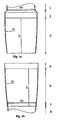
- a male part in Fig. 1a, a male part and in Fig. 1b, a corresponding sleeve part of an embodiment A is shown.
- the plug-in part is the end piece of a pipe 1 with a nominal cross section DN and has an end 2,3 extended over the nominal cross section DN.
- the configuration of the widening 2 from the nominal diameter DN to the section can take place in a suitable manner and is shown only by way of example as a section-wise linear widening. To the Expansion 2 is followed by an area with a non-linear, continuous section 3.
- the portion 3 has a constant curvature, i. the section forms a section of a circle.
- the section has a fixed outer radius R1 and the length H2.
- the spatial body which is formed by the rotation of this circular section around the tube axis as a spherical segment.
- the sleeve part is the end piece of a tube 8 with the nominal cross-section DN, as shown in Fig. 1b, and has an end 7,6,5 extended over the nominal cross-section DN.
- the configuration of the widening 7 from the nominal diameter DN to the section can be effected in a suitable manner is shown only by way of example as a section-wise linear widening.
- the expansion 7 also have a bead as Kapillarsperre.
- the widening 7 is adjoined by an area with a non-linear, continuous section 6.
- the portion 6 has a constant curvature, i. the section forms a section of a circle.
- the section has a fixed inside radius R1 and the length H1.
- the spatial body which is formed by the rotation of this circular section around the tube axis as a spherical segment.
- the socket part may have a receptacle 5 at the upper end.
- the configuration of the receptacle 5 can be done in a suitable manner is shown only as an example as a section linear.
- the receptacle 5 of the sleeve part is designed so that it serves as a stop line for the attachment and alignment of a clamping band, if the attachment of such a band should be required.
- the execution of the recording 5 allows the sleeve part be designed so that they tolerances, eg manufacturing tolerances, and / or damage, such as transport damage, the male part receives when plugging.
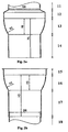
- FIG. 2 a shows a plug-in part and, in FIG. 2 b, a corresponding sleeve part of an embodiment B.
- the insertion part is the end piece of a pipe 11 with a nominal cross-section DN and has an end 12, 13, 14 which is widened over the nominal cross-section DN.
- the configuration of the widening 12 from the nominal diameter DN to the section can be effected in a suitable manner is shown only by way of example as a section-wise linear widening.
- the widening 12 is followed by an area with a non-linear, continuous section 13.
- the portion 13 has a constant curvature, i. the section forms a section of a circle.
- the section has a fixed outer radius R2 and the length H6.
- the spatial body which is formed by the rotation of this circular section around the tube axis as a spherical segment.
- the male member may have a cylindrical portion 14 at the lower end.
- the configuration of section 14 is a cylindrical section having a length resulting from the difference of H4 and H6.
- the cylindrical portion 14 has the nominal diameter DN.
- the cylindrical portion 14 may be shorter in its length (H4-H6) than the section 13.
- the length dimensioning is only exemplary, other suitable length dimensioning are also possible.
- the present embodiment of the cylindrical portion 14 serves to further stiffen the pipe to further protect the pipe end and in particular the non-linear, continuous portion 13 from damage and deformation, eg by transport damage.
- the sleeve part as shown in FIG. 2b, is the end piece of a pipe 18 with the nominal cross section DN and has an end 17, 16, 15 which is widened over the nominal cross section DN.
- the configuration of the widening 17 from the nominal diameter DN to the widened part can take place in a suitable manner is shown only by way of example as a section-wise linear widening.
- the expansion has a length resulting from the difference of H3 and H5.
- the widening 17 has a diameter that is greater than the nominal diameter DN. Preferably, it has a diameter which is found to be suitable for the section 14.
- the expansion 17 may be shorter in length (H3-H5) than the section 16.
- the length dimensioning is only exemplary, other suitable length dimensioning are also possible.
- the widening 17 could also have a bead as a capillary barrier.
- the widening 17 is followed by an area with a non-linear, continuous section 16.
- the portion 16 has a constant curvature, i. the section forms a section of a circle.
- the section has a fixed inner radius R1 and has the length H5.
- the spatial body which is formed by the rotation of this circular section around the tube axis as a spherical segment.
- the socket part has a receptacle 15 at the upper end.
- the configuration of the receptacle 15 can take place in a suitable manner is shown only as an example as a sectionally linear recording.
- the receptacle 15 of the sleeve part is designed so that it serves as a stop line for the attachment and alignment of a clamping band, if the attachment of such a band should be required.
- the execution of the receptacle 15 allows the sleeve part be designed so that they tolerances, eg manufacturing tolerances, and / or damage, such as transport damage, the male part receives when plugging.
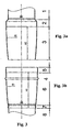
- FIG. 3 a shows a plug-in part and FIG. 3 b shows a corresponding socket part of an embodiment C, which differs from embodiment A only in that a capillary barrier 4 is provided in section 6 of the socket part.
- Fig. 4 shows an embodiment D of the invention, which relates to a double-walled plug-in system.
- the connection of the plug-in system would generally be realized by means of a clamping band, not shown.
- Fig. 5 shows a further embodiment E of a double-walled plug-in system.
- the tubes of the male and the female part are characterized by a self-locking design.
- the invention thus provides a pipe system with a form-fitting metallic seal, since the sections 3 and 6 or 13 and 16 are in a form-fitting manner against one another when they are guided into one another by the selection of identical curved courses.
- the tightness is realized by a plurality of closed circumferential curves.
- the pipe system according to the invention also offers the possibility of pipes which are not collinear in their axes, by means of a hinged connection connect while meeting the requirements for tightness.
- section H2 is shorter than the Section H1 is the widening 2 quickly to the nominal diameter DN of the tube 1 passes and the receptacle 5 is omitted or short and / or widened compared to the diameter reached at the end of the section 6, so also tubes whose axis alignment can not be matched into each other .
- a suitable curve selection eg if the curve of sections 3 and 6 have a fixed radius R1, the two pipe ends close together in a form-fitting manner and provide the required tightness.
- sealing elements subject to the use of other, partially strong attacking and / or aging processes, such as e.g. Sealing lips, sealing rings or sealing pastes are dispensed on a different basis.
Landscapes
- Engineering & Computer Science (AREA)
- General Engineering & Computer Science (AREA)
- Mechanical Engineering (AREA)
- Chemical & Material Sciences (AREA)
- Combustion & Propulsion (AREA)
- Quick-Acting Or Multi-Walled Pipe Joints (AREA)
- Rigid Pipes And Flexible Pipes (AREA)
- Branch Pipes, Bends, And The Like (AREA)
- Pipe Accessories (AREA)
- Electric Cable Installation (AREA)
Abstract
Description
Die Erfindung betrifft ein Stecksystem für Rohrverbindungen mit nichtlinearen kontinuierlichen Abschnitten zur Verwendung im industriellen, häuslichen sowie im automobilen Bereich.The invention relates to a plug-in system for pipe joints with non-linear continuous sections for use in industrial, domestic as well as in the automotive sector.
Auf dem Gebiet der Haustechnik sind insbesondere im Bereich der Abgasanlagen und der Lüftungs- und Klimatechnik Stecksystem für Rohrverbindungen zur Zu- und / oder Ableitung von Gasen im Einsatz. Ebenso sind Stecksystem für Rohrverbindungen im Automobilbau und auch im stationären Bereich, wie z.B. bei Blockheizkraftwerken, wo Abgase aus einem Motor abgeleitet werden, im Einsatz.In the field of building services, especially in the field of exhaust systems and ventilation and air conditioning plug-in system for pipe connections for the supply and / or discharge of gases in use. Likewise, plug-in systems for pipe connections in the automotive industry and also in the stationary sector, such as. in cogeneration plants, where exhaust gases are discharged from a motor, in use.
Insbesondere die Ableitung von aggressiven Gasen, wie z.B. Abgasen aus Verbrennungsanlagen, stellt hohe Anforderungen an die Dichtigkeit des Rohrsystems.In particular, the discharge of aggressive gases, e.g. Exhaust gases from incineration plants make high demands on the tightness of the pipe system.
Typische Verbrennungsanlagen sind Wärmeerzeugungsanlagen und Motoren, wie sie zur Warmwasserbereitung, zu Heizzwecken, zur Stromerzeugung, zu Antriebszwecken, als Blockheizkraftwerke oder ähnlichem im häuslichen, industriellen sowie im automobilen Bereich zur Anwendung kommen.Typical incinerators are heat generators and engines, such as those used for hot water, for heating purposes, for power generation, for drive purposes, as combined heat and power plants or the like in the domestic, industrial and in the automotive sector.
Ein weiterer Einsatzbereich dieser Rohrsysteme ist die Zuleitung von Gasen, z.B. von Frischluft. Solche Anlagen können in jedem Bereich zur Anwendung kommen, also insbesondere auch in der Klimatechnik, z.B. auch für Klimaanlagen im häuslichen und industriellen Bereich.Another area of application of these pipe systems is the supply of gases, eg fresh air. Such systems can be used in any field, so in particular in the air conditioning, for example, for domestic and industrial air conditioning systems.
Stecksysteme eignen sich sowohl für den Neubau als auch die Sanierung und Reparatur von Altanlagen.Plug-in systems are suitable for both the new construction as well as the renovation and repair of old systems.
Weiterhin können diese Anlagen auch kombiniert zur Anwendung kommen, z.B. zur gleichzeitigen Führung von zwei Gasen, beispielsweise kann über das Außenrohr, eine Heizungsanlage mit Verbrennungsluft versorgt werden, während das Innenrohr das Abgas / die Abluft ableitet.Furthermore, these systems can also be used in combination, e.g. for the simultaneous guidance of two gases, for example, can be supplied via the outer tube, a heating system with combustion air, while the inner tube discharges the exhaust / the exhaust air.
Bei der Sanierung von Kaminen beispielsweise wird kaminseitig ein Kaminrohr bestehend aus mehreren Rohrabschnitten in den Kaminschacht eingebracht. Ein sich gegebenenfalls zwischen dem eingebrachten Kaminrohr und einem in den Kaminschacht eingebrachten Außenrohr ergebender Zwischenraum kann mit Isoliermaterial versehen werden.In the renovation of chimneys, for example, a chimney pipe consisting of several pipe sections is introduced into the chimney flue. A possibly resulting between the introduced chimney pipe and an introduced into the chimney tube outer tube resulting space can be provided with insulating material.
Weiterhin können die Systeme auch doppelwandig vormontiert ausgeführt sein und mit isolierenden Material vorgesehen sein.Furthermore, the systems can also be designed double-walled pre-assembled and provided with insulating material.
Typische Isolationsmaterialien sind z.B. Mineralfasern, Keramikgewebe, Keramikflies, oder dergleichen hergestellt.Typical insulation materials are, for example, mineral fibers, ceramic fabrics, ceramic tiles, or the like.
Systeme, die z.B. in der Abgastechnik verwendet werden, sind beispielsweise aus den Europäischen Patenten EP 0 780 635 B1, EP 0 286 488 B1 und EP 0 798 513 B1, der Europäischen Patentanmeldung EP 1 188 979 A2, der Deutschen Offenlegungsschrift DE 195 19 073 A1 sowie dem Deutschen Gebrauchsmuster DE 91 01 262 U1 bekannt.Systems, e.g. used in the exhaust gas technology are, for example, from the European patents EP 0 780 635 B1, EP 0 286 488 B1 and EP 0 798 513 B1, the European
Das Europäische Patent EP 0 780 635 B1 betrifft ein Kaminrohr für die Schornsteinsanierung aus mehreren Rohrabschnitten, die jeweils ein konisch erweitertes Ende und ein konisch verjüngtes Ende mit gleichen Konuswinkeln aufweisen und die durch Einstecken des verjüngten Endes in das erweiterte Ende miteinander verbindbar sind. Diese konischen Abschnitte haben jedoch die Eigenschaft empfindlich auf Beschädigungen, wie z.B. Transportschäden, zu reagieren, da die linear Fläche bei Beschädigungen einen erwünschten Formschluss nicht länger zulässt.European Patent EP 0 780 635 B1 relates to a chimney pipe for the chimney rehabilitation of a plurality of pipe sections, each having a flared end and a conically tapered end with the same cone angles and which are connectable by inserting the tapered end in the extended end. However, these conical portions are sensitive to damage such as e.g. Transport damage, to react, since the linear surface no longer allows a desired positive locking in case of damage.
Ähnliche Systeme sind aus den Europäischen Patenten EP 0 286 488 B1 und EP 0 798 513 B1 und der Deutschen Offenlegungsschrift DE 195 19 073 A1 bekannt.Similar systems are known from European patents EP 0 286 488 B1 and EP 0 798 513 B1 and German laid-open specification DE 195 19 073 A1.
Weiterhin weisen die bisherigen System das Problem auf, das Rohre die in ihren Achsen nicht kollinear sind, nicht zuverlässig dichtend aufgebaut werden können, da das Einführen eines nicht kollinearen Rohrendes zu einer Verformung der Konen und damit zu einer Verletzung der Dichtigkeitsanforderung führen kann.Furthermore, the previous systems have the problem that pipes which are not collinear in their axes, can not be constructed reliably sealing, since the introduction of a non-collinear pipe end can lead to deformation of the cones and thus to a violation of Dichtigkeitsanforderung.
Weiterhin wirkt bei diesen Rohrelementen bei einer vertikalen Verbindung nur das Gewicht der oberhalb der jeweils betrachteten Rohrverbindungen angeordneten Rohrelemente stabilisierend auf die Steckverbindung. Für den Fall jedoch, dass sich die betrachtete Rohrverbindung im oberen Bereich befindet, kann es sein, dass die zur Verfügung stehende Gewichtskraft der oberhalb befindlichen Rohrelemente nicht mehr zu einer Stabilisierung der Rohrverbindung ausreicht.Furthermore, in the case of a vertical connection, only the weight of the tubular elements arranged above the respectively considered pipe connections has a stabilizing effect on the plug connection in the case of these pipe elements. However, in the event that the considered pipe joint is in the upper region, it may be that the available weight force of the pipe elements located above is no longer sufficient to stabilize the pipe joint.
Weiterhin stellen konische Rohrelemente bei einem Konuswinkel der 7° übersteigt, wegen des geringen Reibschlusses, keine Selbsthemmung mehr zur Verfügung.Furthermore conical tube elements at a cone angle of 7 ° exceeds, because of the low frictional engagement, no more self-locking more available.
Wegen der axialen Ausrichtung der Abschnitte kommt es bei einer horizontalen Verbindung infolge der Schwerkraft der einzelnen Rohrelemente zu einer Verformung im Abschnitt der Rohrabschnitte und dadurch ist die geforderte Dichtigkeit nicht mehr gewährleistet.Because of the axial alignment of the sections occurs in a horizontal connection due to the gravity of the individual pipe elements to a deformation in the section of the pipe sections and thus the required tightness is no longer guaranteed.
Das Deutsche Gebrauchsmuster DE 91 01 262 U1 offenbart eine Einrichtung, die ein einfaches Anschließen eines Gerätes an einen fest angeordneten Leitungsabschnitt ermöglichen soll. Hierzu wird in mehrstückiges Zwischenglied vorgeschlagen, bei dem die inneren Stückenden der Leitungsabschnitte ballig ausgebildet sein können. Der Endbereich dieser ballig ausgebildeten Enden wird in ballig ausgebildeten Enden der zu verbindenden Leitungsabschnitte gehalten.The German Utility Model DE 91 01 262 U1 discloses a device which is intended to enable a simple connection of a device to a fixed line section. For this purpose, it is proposed in multi-piece intermediate member in which the inner piece ends of the line sections can be formed crowned. The end region of these spherically formed ends is held in crowned ends of the line sections to be connected.
Dabei stellt der innere Teil des mehrstückigen Zwischenstücks ein Kugelgelenk dar. Ein Kugelgelenk erfordert ein Übergreifen, da nur so eine Halterung realisiert werden kann. Eine solche Halterung widerspricht jedoch einem Stecksystem, denn das innere Rohr muss nach dem Einführen von innen umgeformt werden, um eine solche Halterung zu ermöglichen. Ein solches System stellt dann aber kein Stecksystem mehr dar.In this case, the inner part of the multi-piece intermediate piece is a ball joint. A ball joint requires an overlap, since only such a holder can be realized. However, such a bracket contradicts a plug-in system, because the inner tube must be transformed after insertion from the inside to allow such a holder. But such a system is no longer a plug-in system.
Die bekannten Systeme zeigen sich bezüglich ihrer Dichtigkeit als problematisch. Prinzipbedingt erreichen sie nur eine unzureichende flächenhafte Dichtung durch eine flächenhafte konische Pressung, die durch weitere Maßnahmen erhöht werden muss.The known systems are problematic in terms of their tightness. Due to the principle, they only achieve an insufficient areal seal due to a planar conical pressing, which must be increased by further measures.
Dieses Problem wird zum einen dadurch angegangen, dass Dichtungsmaterialien, wie z.B. Dichtringe, Dichtlippen oder Dichtpasten, eingesetzt werden, zum anderen dadurch dass zusätzliche Klemmelemente, wie z.B. Rohrschellen, eingesetzt werden, um die geforderte Dichtigkeit zu erreichen.This problem is addressed on the one hand by the fact that sealing materials, such as e.g. Sealing rings, sealing lips or sealing pastes, are used, on the other hand that additional clamping elements, such. Clamps are used to achieve the required tightness.
Im Bereich der Abgastechnik werden zudem hohe Anforderungen gestellt, da hier Temperaturen von über 600° C und Drücke über 50 hPa auftreten können. Weiterhin enthalten die Abgase aggressive Bestandteile, wie z.B. SO2, SO3, NO, NO2, NO3. Lösen sich diese in Wasser, das auch in Form von Wasserdampf Bestandteil der Verbrennungsluft ist, so bildet sich ein höchst aggressives Kondensat.In the field of exhaust gas technology, high demands are also made because temperatures of more than 600 ° C and pressures above 50 hPa can occur here. Farther The exhaust gases contain aggressive components, such as SO 2 , SO 3 , NO, NO 2 , NO 3 . Dissolve these in water, which is also part of the combustion air in the form of water vapor, so it forms a highly aggressive condensate.
Bei diesen Anforderungen sind bekannte Dichtmaterialien wie z.B. Kautschuke auf Silikonbasis oder Fluorbasis nicht oder nur mit Einschränkungen verwendbar, da diese durch schweflige Bestandteile, wie z.B. schweflige Säure oder Schwefelsäure, und / oder salpetrige Bestandteile, wie z.B. salpetrige Säure oder Salpetersäure, in den Abgasen bzw. dem Kondensat der Verbrennungsluft angegriffen und sogar durch Aufkonzentration zerstört werden können.In these requirements, known sealing materials such as e.g. Silicone-based or fluorine-based rubbers are not usable or can be used only to a limited extent since they are formed by sulfurous constituents, such as sulfuric acid. sulphurous acid or sulfuric acid, and / or nitrous ingredients, e.g. nitrous acid or nitric acid, attacked in the exhaust gases or the condensate of the combustion air and can even be destroyed by concentration.
Zur Gewährleistung der Dichtheit werden daher die Dichtigkeit unterstützenden Elementen, wie z.B. Rohrschellen, benötigt.To ensure tightness, therefore, the leak-proofing elements, e.g. Pipe clips, needed.
Die Europäischen Patentanmeldung EP 1 188 979 A2 betrifft eine Rohrverbindung, die zusätzlich zu der bereits bekannten Verbindungseinrichtung eine Vorspanneinrichtung in Form von Federbügeln aufweist, dergestalt, dass in deren Wirkstellung eine in Achsenrichtung wirkende Haltekraft auf die Rohrleitungsabschnitte ausgeübt wird.European
Rohrschellen oder diesen ähnlichen Elemente wirken radial auf die Rohrverbindung. Eine axiale Sicherung der Verbindung können diese nur unzureichend erreichen.Pipe clamps or similar elements act radially on the pipe joint. An axial securing of the connection can only achieve this inadequately.
Weiterhin erfordert die Montage entsprechender Elemente zum einen Werkzeug, zum anderen auch den nötigen Freiraum, um die Elemente dauerhaft anbringen zu können. Dieser Umstand ist insbesondere bei Sanierungen nicht immer gegeben.Furthermore, the installation of appropriate elements requires a tool, on the other hand, the necessary space to permanently attach the elements can. This circumstance is not always given, especially in renovations.
Weiterhin gibt es die Möglichkeit, die Rohrelemente mechanisch beim Aufbau durch Einsatz von entsprechenden Montagewerkzeug durch Formänderung aufzuweiten und zu verbinden. Darüber hinaus besteht die Möglichkeit einer dauerhaften Verbindung der Rohrelemente. Diese Alternativen erschweren jedoch etwaige spätere Reparaturen oder eine Sanierung erheblich.Furthermore, there is the possibility of mechanically expanding and connecting the tubular elements during construction by using appropriate assembly tool by changing the shape. In addition, there is the possibility of a permanent connection of the pipe elements. These alternatives, however, make any subsequent repairs or refurbishment considerably more difficult.
Der Erfindung liegt die Aufgabe zugrunde, ein Stecksystem für Rohrverbindungen zur Verfügung zu stellen, dass eine zuverlässige Dichtung bietet. Es ist weiterhin Aufgabe der Erfindung, ein Stecksystem für Rohrverbindungen zur Verfügung zu stellen, das einfach montierbar ist. Es ist weiterhin Aufgabe der Erfindung, ein Stecksystem für Rohrverbindungen zur Verfügung zu stellen, das sowohl bei horizontaler als auch vertikaler Verwendung dichtet. Es ist weiterhin Aufgabe der Erfindung ein Stecksystem für Rohrverbindungen zur Verfügung zu stellen, dass auf den Einsatz weiterer die Dichtigkeit unterstützender Mittel verzichtet oder minimiert. Es ist weiterhin Aufgabe der Erfindung ein Stecksystem für Rohrverbindungen bereit zu stellen, dass auch nicht kollineare Rohrverbindungen mit einer zuverlässigen Dichtigkeit und einer besseren Selbsthemmung zur Verfügung stellt.The invention has for its object to provide a connector system for pipe joints that provides a reliable seal. It is a further object of the invention to provide a plug-in system for pipe connections available, which is easy to install. It is a further object of the invention to provide a plug-in system for pipe joints, which seals both in horizontal and vertical use. It is a further object of the invention to provide a plug-in system for pipe connections that dispenses or minimizes the use of further leakproofing means. It is a further object of the invention to provide a plug-in system for pipe connections that also provides non-collinear pipe connections with a reliable tightness and better self-locking available.
Die Aufgaben werden durch ein Stecksystem für Rohrverbindungen gelöst, wobei ein Ende eines einwandigen Rohrs als Einsteckteil und ein Ende eines einwandigen Rohrs als Muffenteil ausgebildet ist, und sowohl das Einsteckteil als auch das Muffenteil einen nichtlinearen kontinuierlichen Abschnitt aufweisen.The objects are achieved by a plug-in system for pipe connections, wherein one end of a single-walled tube is formed as a male part and one end of a single-walled tube as a sleeve part, and both the male part and the female part have a non-linear continuous portion.
Das Einsteckteil ist das Endstück eines Rohres und weist ein erweitertes Ende auf.The male is the end of a tube and has an extended end.
Die Ausgestaltung der Aufweitung auf das erweiterte Ende kann in geeigneter Weise erfolgen. Beispielsweise kann die Aufweitung abschnittsweise linear sein, jedoch ist auch jeder andere Gestaltung möglich, beispielsweise ein nichtlinearer, kontinuierlicher Verlauf.The configuration of the expansion to the extended end can be done in a suitable manner. For example, the widening sections may be linear, but any other design is possible, for example, a non-linear, continuous course.
An die Aufweitung schließt sich ein nichtlinearer kontinuierlicher Abschnitt an. Die Gestaltung des nichtlinearen kontinuierlichen Abschnitts kann dabei unterschiedliche Formen aufweisen.The widening is followed by a non-linear continuous section. The design of the non-linear continuous section can have different shapes.
Bevorzugt weist der nichtlineare kontinuierliche Abschnitt eine konstante Krümmung auf, es wäre jedoch auch möglich eine sich kontinuierlich ändernde, z.B. eine sich monoton ändernde Krümmung vorzusehen.Preferably, the nonlinear continuous section has a constant curvature, but it would also be possible to provide a continuously changing, eg a monotonically changing, curvature.
Das Muffenteil ist das Endstück eines Rohrs und weist ein erweitertes Ende auf.The sleeve part is the end piece of a pipe and has an extended end.
Die Ausgestaltung der Aufweitung auf das erweiterte Ende kann in geeigneter Weise erfolgen. Beispielsweise kann die Aufweitung abschnittsweise linear sein, jedoch ist auch jeder andere Gestaltung möglich, beispielsweise ein nichtlinearer kontinuierlicher Verlauf.The configuration of the expansion to the extended end can be done in a suitable manner. For example, the widening sections may be linear, but any other design is possible, for example, a non-linear continuous course.
An die Aufweitung schließt sich ein nichtlinearer kontinuierlicher Abschnitt an. Die Gestaltung des nichtlinearen kontinuierlichen Abschnitt kann wiederum dabei unterschiedliche Formen aufweisen.The widening is followed by a non-linear continuous section. The design of the non-linear continuous section may in turn have different shapes.
Bevorzugt weist auch dieser nichtlineare kontinuierliche Abschnitt eine konstante Krümmung auf, es wäre jedoch auch möglich eine sich kontinuierlich ändernde, z.B. eine sich monoton ändernde Krümmung vorzusehen.Preferably, this nonlinear continuous section also has a constant curvature, but it would also be possible to have a continuously changing, e.g. to provide a monotonically changing curvature.
Weiterhin kann das Muffenteil eine Aufnahme am oberen Ende aufweisen. Die Ausgestaltung der Aufnahme kann in geeigneter Weise erfolgen Beispielsweise kann die Aufnahme abschnittsweise linear sein, jedoch ist auch jede andere Gestaltung möglich, beispielsweise ein nichtlinearer, kontinuierlicher Verlauf.Furthermore, the sleeve part may have a receptacle at the upper end. The configuration of the receptacle can be carried out in a suitable manner. For example, the receptacle can be linear in sections, but any other design is possible, for example, a non-linear, continuous course.
Durch Wahl eines nichtlinearen kontinuierlichen Abschnitts ergibt sich, dass in allen Punkten auf dem Abschnitt beim Anliegen eines Einsteckteils eines Rohres an dem entsprechenden Muffenteil eines Rohres sowohl eine axiale als auch eine radiale Kraftkomponente vorhanden ist, die sich von benachbarten Punkt unterscheidet.By choosing a non-linear continuous section, it will be seen that in all points on the section, when a male member of a tube abuts the corresponding female part of a tube, there will be both an axial and a radial force component different from adjacent ones.
Bei einem linearen Verlauf dieses Abschnitts, d.h. wenn der Abschnitt konisch wäre, würde in allen Punkten des Abschnitts die selben Kraftkomponenten in axialer und radialer Richtung wirken.In a linear course of this section, i. if the section were conical, the same force components would act in the axial and radial directions at all points in the section.
Durch Wahl einer formschlüssigen Ausgestaltung wird eine mindestens linienhafte metallische Dichtung erreicht. Die linienhafte Dichtung ergibt sich durch das Aneinanderliegen des Einsteckteils am Muffenteil mit einer bestimmten normal zur Fläche wirkenden Kraft. Dadurch ergibt sich mindestens ein geschlossener umfänglicher Linienzug, ab dem die Dichtheit erreicht ist. Im Normalfall werden sich eine Vielzahl von geschlossenen umfänglichen Linienzügen ergeben, bei den die Dichtheit erreicht ist.By choosing a form-fitting design, an at least linear metallic seal is achieved. The linear seal results from the Butting of the male part on the sleeve part with a certain force acting normal to the surface. This results in at least one closed circumferential polyline, from which the tightness is achieved. Normally, a large number of closed circumferential lines will result, in which the tightness is achieved.
Durch die Wahl eines nichtlinearen kontinuierlichen Abschnitts kann das erfindungsgemäße Stecksystem bei Einhaltung der Dichtheitsbedingungen in jeder Montageposition, also sowohl vertikal als auch horizontal, verlegt werden, da es immer einen geschlossenen umfänglichen Linienzug gibt, auf dem eine bestimmte Kraft überschritten wird, so dass die Dichtheitsanforderungen erfüllt ist.By choosing a non-linear continuous section, the plug-in system according to the invention can be installed in compliance with the tightness conditions in each mounting position, ie both vertically and horizontally, since there is always a closed circumferential polyline on which a certain force is exceeded, so that the tightness requirements is satisfied.
Weiterhin kann durch eine geeignete Wahl erreicht werden, dass das erfindungsgemäße Rohrsystem weiterhin die Möglichkeit bietet auch Rohre, die in ihren Achsen nicht kollinear sind, mit Hilfe einer gelenkartige Verbindung zu verbinden bei gleichzeitiger Erfüllung der Anforderungen an die Dichtheit.Furthermore, it can be achieved by a suitable choice that the pipe system according to the invention also offers the possibility to connect pipes that are not collinear in their axes, using a hinged connection while fulfilling the requirements of the tightness.
Wenn z.B. der Abschnitt des Einsteckteils kürzer als der Abschnitt des Muffenteils ist, die Aufweitung des Einsteckteils schnell auf das Rohr des Einsteckteils übergeht und die Aufnahme entfällt oder kurz ist und / oder gegenüber dem erreichten Durchmesser am Ende des Abschnitts des Muffenteils verbreitert ist, so können auch Rohre deren Achsenausrichtung nicht übereinstimmt, also Rohre, die nicht kollinear sind, ineinandergeführt werden.If e.g. the portion of the male part is shorter than the portion of the female part, the widening of the male part quickly merges with the tube of the male part and the receptacle is omitted or short and / or widened with respect to the diameter reached at the end of the portion of the female part, so can tubes their axis alignment does not match, so pipes that are not collinear, are merged into each other.
Bei geeigneter Gestaltung der Abschnitte, z.B. wenn die Abschnitte einen festen Radius aufweisen, schließen die beiden Rohrenden formschlüssig aneinander und bieten die geforderte Dichtigkeit, auch wenn die Achsen der Rohre nicht kollinear sind.With suitable design of the sections, e.g. if the sections have a fixed radius, the two pipe ends close together form-fitting and provide the required tightness, even if the axes of the pipes are not collinear.
Beim Einführen eines Rohrendes eines Einsteckteils in ein entsprechendes Muffenteil zentriert sich das Rohrende durch geeignete nichtlineare kontinuierliche Abschnitte des Muffenteils erheblich schneller als bei einem linearen, konischen Abschnitt.When inserting a pipe end of a male part into a corresponding female part, the pipe end is centered considerably faster by suitable non-linear continuous sections of the female part than in the case of a linear conical section.
Da das erfindungsgemäße Rohrsystem durch seinen mechanisch-konstruktiven Aufbau bereits zu einer ausreichenden Dichtheit sowohl im horizontalen als auch im vertikalen Betrieb führt, kann auf weitere Elemente, die zur Erreichung einer geforderten Dichtigkeit führen, verzichtet werden.Since the pipe system according to the invention by its mechanical construction already leads to a sufficient tightness in both horizontal and vertical operation, can be dispensed with further elements that lead to the achievement of a required tightness.
Insbesondere sind keine weiteren Klemmelemente zur Einhaltung der Dichtigkeit erforderlich. Klemmelemente können jedoch in vibrationsgefährdeten Umgebungen zur unterstützenden Stabilisierung der Verbindung eingesetzt werden. Weiterhin kann auch auf den Einsatz anderer, teilweiser starken Angriffs- und / oder Alterungsprozessen unterliegenden Dichtelemente, wie z.B. Dichtlippen, Dichtringe oder Dichtpasten auf unterschiedlicher Basis verzichtet werden.In particular, no further clamping elements to maintain the tightness are required. Clamping elements can however be used in vibration-prone environments to assist in stabilizing the connection. Furthermore, sealing elements subject to the use of other, partially strong attacking and / or aging processes, such as e.g. Sealing lips, sealing rings or sealing pastes are dispensed on a different basis.
Weiterhin wird für den Aufbau eines erfindungsgemäßen Rohrsystems kein weiteres Presswerkzeug zur Aufweitung benötigt, um eine Klemmdichtung zu erstellen.Furthermore, no further pressing tool for widening is required for the construction of a pipe system according to the invention in order to create a clamping gasket.
Durch die nichtlineare kontinuierliche Form der Abschnitte verteilen sich Krafteinwirkungen, z.B. durch transporttypische Stöße, besser auf die Gesamtstruktur. Da diese variiert, werden solche Einwirkungen mechanisch besser aufgenommen und es kommt zu keiner wesentlichen, die Dichtheit gefährdenden, dauerhaften plastischen Verformung.The non-linear continuous shape of the sections distributes forces, e.g. through transport-typical impacts, better on the overall structure. Since this varies, such effects are mechanically better absorbed and there is no significant, the tightness endangering, permanent plastic deformation.
Weiterhin ergibt sich, dass auch bei leichten Beschädigungen noch eine wirksame Dichtheit erreicht wird, da bereits ein einziger geschlossener umfänglicher Linienzug aus einer Vielzahl von geschlossenen umfänglichen Linienzüge zur Erfüllung der Dichtheit führt.Furthermore, it follows that even with slight damage still an effective tightness is achieved, since even a single closed circumferential polyline of a plurality of closed circumferential polylines leads to the fulfillment of the tightness.
Das erfindungsgemäße Stecksystem bietet die Möglichkeit die Rohre von selbsthemmend bis leicht lösbar sowohl in horizontaler als auch vertikaler Ausrichtung zu verbinden. Dies kann durch geeignete Wahl der nichtlinearen kontinuierlichen Abschnitt, z. B. durch Wahl eines entsprechenden Radius bewerkstelligt werden.The plug-in system according to the invention offers the possibility of connecting the pipes from self-locking to easily detachable both in horizontal and vertical orientation. This can be done by suitable choice of the nonlinear continuous section, e.g. B. be accomplished by choosing a corresponding radius.
Weiterhin kann das erfindungsgemäße Stecksystem eine Sicke aufweisen, die als Kapillarsperre und / oder als Feuchtigkeitssammler dient und einen Austritt von Kondensat verhindert.Furthermore, the plug-in system according to the invention may have a bead, which serves as a capillary barrier and / or as a moisture collector and prevents leakage of condensate.
Weiterhin kann die Aufnahme des Muffenteils so ausgeführt sein, dass sie als Anschlagslinie für die Anbringung und Ausrichtung eines Klemmbandes dient, falls die Anbringung eines solchen Bandes erforderlich sein sollte.Furthermore, the receptacle of the sleeve part can be designed so that it serves as a stop line for the attachment and alignment of a clamping band, if the attachment of such a band should be required.
Weiterhin kann die Aufnahme des Muffenteils so ausgeführt sein, dass sie Toleranzen, z.B. fertigungsbedingte Toleranzen, und / oder Beschädigungen, z.B. Transportschäden, des Einsteckteils aufnimmt.Furthermore, the receptacle of the sleeve part can be designed so that it tolerances, e.g. manufacturing tolerances, and / or damage, e.g. Transport damage, the plug-in part absorbs.
Weiterhin kann das Rohrende des Einsteckteil einen zylindrischen Abschnitt aufweisen, der zu einer weiteren Versteifung des Rohres und insbesondere des nichtlinearen kontinuierlichen Abschnitts führt.Furthermore, the tube end of the male member may have a cylindrical portion leading to further stiffening of the tube and in particular of the non-linear continuous portion.
Als Basismaterial wird Stahl und insbesondere Edelstahl bevorzugt, jedoch sind andere metallische Werkstoffe auch denkbar.As a base material steel and especially stainless steel is preferred, but other metallic materials are also conceivable.
Weiterhin bevorzugt ist, dass die Rohre aus einem flächenhaften Material durch Stanzen oder Schneiden in einer Rohform herausgearbeitet werden und in weiteren Schritten zu Rohrrohlingen gebogen und verschweißt werden. Weitere Schritte umfassen das Umformen der Rohrenden zu den vorbenannten nichtlinearen kontinuierlichen Abschnitten.It is further preferred that the tubes are machined from a sheet material by punching or cutting in a raw form and bent in further steps to tube blanks and welded. Other steps include reshaping the pipe ends to the aforementioned nonlinear continuous sections.
Die vorgenannten Systeme können sowohl ein- als auch doppelwandig ausgeführt sein und bei einer doppelwandigen Ausführung entweder mit isolierenden Material und / oder der Möglichkeit zur Führung eines weiteren Gases vorgesehen sein.The aforementioned systems can be designed as single-walled or double-walled and, in the case of a double-walled construction, can be provided either with insulating material and / or the possibility of guiding a further gas.
Bei einer doppelwandigen Ausführung können Innenrohre und Außenrohre unterschiedliche oder gleiche Krümmung aufweisen.In a double-walled design inner tubes and outer tubes may have different or the same curvature.
Bei doppelwandigen Rohren kann zusätzliche eine Stabilisierung zwischen den Rohren eingefügt werden, entweder durch Einbringen eines Isolationsmaterials, oder durch Abstandshalter.For double-walled pipes, additional stabilization can be inserted between the pipes, either by introducing an insulating material or by spacers.
Typische Isolationsmaterialien sind z.B. Mineralfasern, Keramikgewebe, Keramikvlies, oder dergleichen hergestellt. Als bevorzugtes Material zur Isolierung wird Mineralfaserbasiertes Isolationsmaterial bevorzugt.Typical insulation materials are e.g. Mineral fibers, ceramic fabric, ceramic fleece, or the like. As a preferred material for insulation, mineral fiber based insulation material is preferred.
Das erfindungsgemäße Rohrsystem ist für sämtliche Nennweiten, die für die Abgas- oder Lüftungsanlagen gemäß technischer Auslegung / Berechnung erforderlich sind, anwendbar.The pipe system according to the invention is applicable to all nominal sizes that are required for the exhaust or ventilation systems according to technical design / calculation.
Anhand der Zeichnung wird die Erfindung nachstehend eingehend erläutert.Reference to the drawing, the invention is explained in detail below.
Es zeigt:
- Fig. 1a ein Einsteckteil einer Ausführungsform A der Erfindung,
- Fig. 1b ein Muffenteil einer Ausführungsform A der Erfindung,
- Fig. 2a ein Einsteckteil einer Ausführungsform B der Erfindung,
- Fig. 2b ein Muffenteil einer Ausführungsform B der Erfindung,
- Fig. 3a ein Einsteckteil einer Ausführungsform C der Erfindung,
- Fig. 3b ein Muffenteil einer Ausführungsform C der Erfindung,
- Fig. 4 ein Einsteck- und Muffenteil einer Ausführungsform D der Erfindung,
- Fig. 4 ein Einsteck- und Muffenteil einer Ausführungsform E der Erfindung.
- 1a is a plug-in part of an embodiment A of the invention,
- 1b shows a sleeve part of an embodiment A of the invention,
- 2a shows a plug-in part of an embodiment B of the invention,
- 2b shows a sleeve part of an embodiment B of the invention,
- 3a shows a plug-in part of an embodiment C of the invention,
- 3b shows a sleeve part of an embodiment C of the invention,
- 4 shows a male and female part of an embodiment D of the invention,
- Fig. 4 is a male and female part of an embodiment E of the invention.
In Fig. 1a ist ein Einsteckteil und in Fig. 1b ein entsprechendes Muffenteil einer Ausführungsform A dargestellt.In Fig. 1a, a male part and in Fig. 1b, a corresponding sleeve part of an embodiment A is shown.
Das Einsteckteil ist das Endstück eines Rohres 1 mit einem Nennquerschnitt DN und weist ein über den Nennquerschnitt DN erweitertes Ende 2,3 auf. Die Ausgestaltung der Aufweitung 2 vom Nenndurchmesser DN auf den Abschnitt kann in geeigneter Weise erfolgen und ist nur exemplarisch als abschnittsweise lineare Aufweitung gezeigt. An die Aufweitung 2 schließt sich ein Bereich mit einem nichtlinearen, kontinuierlichen Abschnitt 3 an.The plug-in part is the end piece of a
Bevorzugt weist der Abschnitt 3 eine konstante Krümmung auf, d.h. der Abschnitt bildet einen Ausschnitt eines Kreises. Der Abschnitt hat einen festen Außen-Radius R1 und die Länge H2.Preferably, the
Entsprechend kann man den Raumkörper der durch die Rotation dieser Kreisabschnitts um die Rohrachse entsteht als Kugelsegment beschreiben.Correspondingly, one can describe the spatial body which is formed by the rotation of this circular section around the tube axis as a spherical segment.
Das Muffenteil ist das Endstück eines Rohres 8 mit dem Nennquerschnitt DN, wie in Fig. 1b gezeigt, und weist ein über den Nennquerschnitt DN erweitertes Ende 7,6,5 auf. Die Ausgestaltung des Aufweitung 7 vom Nenndurchmesser DN auf den Abschnitt kann in geeigneter Weise erfolgen ist nur exemplarisch als abschnittsweise lineare Aufweitung gezeigt. Z.B. könnte die Aufweitung 7 auch eine Sicke als Kapillarsperre aufweisen. An die Aufweitung 7 schließt sich ein Bereich mit einem nichtlinearen, kontinuierlichen Abschnitt 6 an.The sleeve part is the end piece of a
Bevorzugt weist der Abschnitt 6 eine konstante Krümmung auf, d.h. der Abschnitt bildet einen Ausschnitt eines Kreises. Der Abschnitt hat einen festen Innen-Radius R1 und die Länge H1.Preferably, the
Entsprechend kann man den Raumkörper der durch die Rotation dieser Kreisabschnitts um die Rohrachse entsteht als Kugelsegment beschreiben.Correspondingly, one can describe the spatial body which is formed by the rotation of this circular section around the tube axis as a spherical segment.
Weiterhin kann das Muffenteil eine Aufnahme 5 am oberen Ende aufweisen. Die Ausgestaltung der Aufnahme 5 kann in geeigneter Weise erfolgen ist nur exemplarisch als abschnittsweise linear gezeigt. In der vorliegenden Ausführungsform ist die Aufnahme 5 des Muffenteils so ausgeführt, dass sie als Anschlagslinie für die Anbringung und Ausrichtung eines Klemmbandes dient, falls die Anbringung eines solchen Bandes erforderlich sein sollte. Weiterhin erlaubt die Ausführung der Aufnahme 5 des Muffenteils so ausgeführt sein, dass sie Toleranzen, z.B. fertigungsbedingte Toleranzen, und / oder Beschädigungen, z.B. Transportschäden, des Einsteckteils beim Einstecken aufnimmt.Furthermore, the socket part may have a
In Fig. 2a ist ein Einsteckteil und in Fig. 2b ein entsprechendes Muffenteil einer Ausführungsform B dargestellt.FIG. 2 a shows a plug-in part and, in FIG. 2 b, a corresponding sleeve part of an embodiment B.
Das Einsteckteil ist das Endstück eines Rohres 11 mit einem Nennquerschnitt DN und weist ein über den Nennquerschnitt DN erweitertes Ende 12,13,14 auf. Die Ausgestaltung der Aufweitung 12 vom Nenndurchmesser DN auf den Abschnitt kann in geeigneter Weise erfolgen ist nur exemplarisch als abschnittsweise lineare Aufweitung gezeigt. An die Aufweitung 12 schließt sich ein Bereich mit einem nichtlinearen, kontinuierlichen Abschnitt 13 an.The insertion part is the end piece of a
Bevorzugt weist der Abschnitt 13 eine konstante Krümmung auf, d.h. der Abschnitt bildet einen Ausschnitt eines Kreises. Der Abschnitt hat einen festen Außen-Radius R2 und die Länge H6.Preferably, the
Entsprechend kann man den Raumkörper der durch die Rotation dieser Kreisabschnitts um die Rohrachse entsteht als Kugelsegment beschreiben.Correspondingly, one can describe the spatial body which is formed by the rotation of this circular section around the tube axis as a spherical segment.
Weiterhin kann das Einsteckteil einen zylindrischen Abschnitt 14 am unteren Ende aufweisen. Die Ausgestaltung des Abschnitt 14 ist ein zylindrischer Abschnitt mit einer Länge, die sich aus der Differenz von H4 und H6 ergibt. Der zylindrische Abschnitt 14 weist den Nenndurchmesser DN auf. Der zylindrische Abschnitt 14 kann in seiner Länge (H4-H6) kürzer sein als der Abschnitt 13. Die Längendimensionierung erfolgt nur exemplarisch, andere geeignete Längendimensionierung sind auch möglich. Die vorliegende Ausführungsform des zylindrischen Abschnitt 14 dient einer weiteren Versteifung des Rohres, um das Rohrende und insbesondere den nichtlinearen, kontinuierlichen Abschnitt 13 weitergehend vor Beschädigungen und Verformungen, z.B. durch Transportschäden zu schützen.Furthermore, the male member may have a
Das Muffenteil, wie in Fig. 2b dargestellt, ist das Endstück eines Rohres 18 mit dem Nennquerschnitt DN und weist ein über den Nennquerschnitt DN erweitertes Ende 17,16,15 auf.The sleeve part, as shown in FIG. 2b, is the end piece of a
Die Ausgestaltung des Aufweitung 17 vom Nenndurchmesser DN auf den erweiterten Teil kann in geeigneter Weise erfolgen ist nur exemplarisch als abschnittsweise lineare Aufweitung gezeigt. Weiterhin weist die Aufweitung eine Länge auf, die sich aus der Differenz von H3 und H5 ergibt. Die Aufweitung 17 weist einen Durchmesser auf, der größer als der Nenndurchmesser DN ist. Bevorzugt weist sie einen Durchmesser auf, der sich als passend für den Abschnitt 14 ergibt. Die Aufweitung 17 kann in ihrer Länge (H3-H5) kürzer sein als der Abschnitt 16. Die Längendimensionierung erfolgt nur exemplarisch, andere geeignete Längendimensionierung sind auch möglich. Weiterhin könnte die Aufweitung 17 auch eine Sicke als Kapillarsperre aufweisen.The configuration of the widening 17 from the nominal diameter DN to the widened part can take place in a suitable manner is shown only by way of example as a section-wise linear widening. Furthermore, the expansion has a length resulting from the difference of H3 and H5. The widening 17 has a diameter that is greater than the nominal diameter DN. Preferably, it has a diameter which is found to be suitable for the
An die Aufweitung 17 schließt sich ein Bereich mit einem nichtlinearen, kontinuierlichen Abschnitt 16 an.The widening 17 is followed by an area with a non-linear,
Bevorzugt weist der Abschnitt 16 eine konstante Krümmung auf, d.h. der Abschnitt bildet einen Ausschnitt eines Kreises. Der Abschnitt hat einen festen Innen-Radius R1 und hat die Länge H5.Preferably, the
Entsprechend kann man den Raumkörper der durch die Rotation dieser Kreisabschnitts um die Rohrachse entsteht als Kugelsegment beschreiben.Correspondingly, one can describe the spatial body which is formed by the rotation of this circular section around the tube axis as a spherical segment.
Weiterhin weist das Muffenteil eine Aufnahme 15 am oberen Ende auf. Die Ausgestaltung des Aufnahme 15 kann in geeigneter Weise erfolgen ist nur exemplarisch als abschnittsweise lineare Aufnahme gezeigt. In der vorliegenden Ausführungsform ist die Aufnahme 15 des Muffenteils so ausgeführt, dass sie als Anschlagslinie für die Anbringung und Ausrichtung eines Klemmbandes dient, falls die Anbringung eines solchen Bandes erforderlich sein sollte. Weiterhin erlaubt die Ausführung der Aufnahme 15 des Muffenteils so ausgeführt sein, dass sie Toleranzen, z.B. fertigungsbedingte Toleranzen, und / oder Beschädigungen, z.B. Transportschäden, des Einsteckteils beim Einstecken aufnimmt.Furthermore, the socket part has a
In Fig. 3a ist ein Einsteckteil und in Fig. 3b ein entsprechendes Muffenteil einer Ausführungsform C dargestellt, das sich von der Ausführungsform A lediglich dadurch unterscheidet, dass eine Kapillarsperre 4 im Abschnitt 6 des Muffenteils vorgesehen ist..FIG. 3 a shows a plug-in part and FIG. 3 b shows a corresponding socket part of an embodiment C, which differs from embodiment A only in that a
Fig. 4 zeigt eine Ausführungsform D der Erfindung, die ein doppelwandiges Stecksystem betrifft. Bei dieser Ausführungsform sind die Rohre des Einsteck- und des Muffenteils, Innen- sowie Außenrohr, als zylindrische Rohre ausgestaltet. Die Verbindung des Stecksystems würde generell mittels eines nicht gezeigten Klemmbandes realisiert werden.Fig. 4 shows an embodiment D of the invention, which relates to a double-walled plug-in system. In this embodiment, the tubes of the male and the female part, inner and outer tube, designed as cylindrical tubes. The connection of the plug-in system would generally be realized by means of a clamping band, not shown.
Fig. 5 zeigt eine weitere Ausführungsform E eines doppelwandigen Stecksystems. Bei dieser Ausführungsform sind die Rohre des Einsteck- und des Muffenteils durch eine selbsthemmende Formgebung gekennzeichnet.Fig. 5 shows a further embodiment E of a double-walled plug-in system. In this embodiment, the tubes of the male and the female part are characterized by a self-locking design.
Die Erfindung stellt somit ein Rohrsystem mit einer formschlüssigen metallischen Dichtung zur Verfügung, da die Abschnitte 3 und 6 bzw. 13 und 16 beim Ineinanderführen durch die Wahl identischer Kurvenverläufe formschlüssig aneinander liegen. Dabei wird die Dichtheit durch eine Vielzahl von geschlossenen umfänglichen Kurvenzügen realisiert.The invention thus provides a pipe system with a form-fitting metallic seal, since the
Durch Wahl eines nichtlinearen kontinuierlichen Abschnittes ergibt sich, dass in allen Punkt auf der Kurve beim Anliegen eines Abschnittes eines Einsteckteils 3 bzw. 6 an den entsprechenden Abschnitt eines Muffenteils 13 bzw. 16 sowohl eine axiale als auch eine radiale Kraftkomponente vorhanden ist, die sich von benachbarten Punkt unterscheidet.By selecting a nonlinear continuous section, it can be seen that at each point on the curve, when a portion of a
Weiterhin kann durch eine geeignete Wahl der Aufweitungen 2 und Aufnahme 5 und der Höhen H1 und H2 der Abschnitte 3 und 6 erreicht werden, dass das erfindungsgemäße Rohrsystem weiterhin die Möglichkeit bietet auch Rohre, die in ihren Achsen nicht kollinear sind, mit Hilfe einer gelenkartige Verbindung zu verbinden bei gleichzeitiger Erfüllung der Anforderungen an die Dichtheit. Wenn z.B. der Abschnitt H2 kürzer als der Abschnitt H1 ist, die Aufweitung 2 schnell auf den Nenndurchmesser DN des Rohrs 1 übergeht und die Aufnahme 5 entfällt oder kurz ist und / oder sich gegenüber dem erreichten Durchmesser am Ende des Abschnittes 6 verbreitert ist, so können auch Rohre deren Achsenausrichtung nicht übereinstimmt ineinandergeführt werden. Bei geeigneter Kurvenwahl, z.B. wenn die Kurve der Abschnitte 3 und 6 einen festen Radius R1 aufweisen, schließen die beiden Rohrenden formschlüssig aneinander und bieten die geforderte Dichtigkeit.Furthermore, it can be achieved by a suitable choice of the
Beim Einführen eines Rohrendes 3 bzw. 14 in ein entsprechendes Muffenteil zentriert sich das Rohrende durch einen geeigneten nichtlinearen kontinuierlichen Abschnitt des Abschnittes 6 bzw. 16 erheblich schneller als bei einer linearen Kurve.When inserting a
Da das erfindungsgemäße Rohrsystem durch seinen mechanisch-konstruktiven Aufbau bereits zu einer ausreichenden Dichtheit sowohl im horizontalen als auch im vertikalen Betrieb führt, kann auf weitere Elemente, die zur Erreichung einer geforderten Dichtigkeit führen, verzichtet werden.Since the pipe system according to the invention by its mechanical construction already leads to a sufficient tightness in both horizontal and vertical operation, can be dispensed with further elements that lead to the achievement of a required tightness.
Insbesondere sind keine weiteren Klemmelemente erforderlich. Weiterhin kann auch auf den Einsatz anderer, teilweiser starken Angriffs- und / oder Alterungsprozessen unterliegenden Dichtelemente, wie z.B. Dichtlippen, Dichtringe oder Dichtpasten auf unterschiedlicher Basis verzichtet werden.In particular, no further clamping elements are required. Furthermore, sealing elements subject to the use of other, partially strong attacking and / or aging processes, such as e.g. Sealing lips, sealing rings or sealing pastes are dispensed on a different basis.
Weiterhin wird für den Aufbau eines erfindungsgemäßen Rohrsystems kein weiteres Presswerkzeug zur Aufweitung benötigt.Furthermore, no further pressing tool for widening is required for the construction of a pipe system according to the invention.
Durch die nichtlineare kontinuierliche Form der Abschnitte 3,13,6,16 verteilen sich Krafteinwirkungen, z.B. durch transporttypische Stöße, besser auf die Gesamtstruktur.Due to the non-linear continuous shape of
Da diese nichtlinear ist, werden solche Einwirkungen mechanisch besser aufgenommen und es kommt zu keiner wesentlichen, die Dichtheit gefährdenden, dauerhaften plastischen Verformung.Since this is non-linear, such effects are mechanically better absorbed and there is no significant, the tightness endangering, permanent plastic deformation.
- 1. Rohr, Einsteckteil1st pipe, plug-in part
- 2. Aufweitung, Einsteckteil2. expansion, plug-in part
- 3. nichtlinearer kontinuierlicher Abschnitt, Einsteckteil3. Non-linear continuous section, male part
- 4. Kapillarsperre4. capillary barrier
- 5. Aufnahme, Muffenteil5. Recording, sleeve part
- 6. nichtlinearer kontinuierlicher Abschnitt; Muffenteil6. nonlinear continuous section; female member
- 7. Aufweitung, Muffenteil7. expansion, socket part
- 8. Rohr, Muffenteil8. Pipe, socket part
- 9.9th
- 10.10th
- 11. Rohr, Einsteckteil11. Pipe, plug-in part
- 12. Aufweitung, Einsteckteil12. expansion, plug-in part
- 13. nichtlinearer kontinuierlicher Abschnitt, Einsteckteil13. Non-linear continuous section, male part
- 14. zylindrischer Abschnitt, Muffenteil14. cylindrical section, socket part
- 15. Aufnahme, Muffenteil15. Recording, sleeve part
- 16. nichtlinearer kontinuierlicher Abschnitt; Muffenteil16. nonlinear continuous section; female member
- 17. Aufweitung, Muffenteil17. expansion, socket part
- 18. Rohr, Muffenteil18th pipe, socket part
Claims (7)
- Connection system for single wall pipe joints used in exhaust, ventilation, or air conditioning technology, in which a end of a single wall pipe is formed as a plug in part (1, 2, 3) and a end of a other single wall pipe is formed as a sleeve part (5, 6, 7, 8) and in which both, when being joined together, overlap in a region (3, 6),
characterized in that
both the plug in part (1, 2, 3) and the sleeve part (5, 6, 7, 8), in said region, comprise a non-linear continuous section (3, 6), in which the non-linear continuous sections serve for sealing the pipe joint through direct contact of the inner surface of the non-linear continuous section of the sleeve part (5, 6, 7, 8) with the outer surface of the non-linear continuous section of the plug in part (1, 2, 3). - Connection system for dual wall pipe joints used in exhaust, ventilation, or air conditioning technology, in which a end of a dual wall pipe is formed as a plug in part (11, 12, 13) and a end of a other dual wall pipe is formed as a sleeve part (15, 16, 17, 18) and in which both, when being joined together, overlap in a region (3, 6),
characterized in that
both the plug in part (11, 12, 13) and the sleeve part (15, 16, 17, 18), in said region, comprise a non-linear continuous section (13, 16), in which the non-linear continuous sections serve for sealing the pipe joint through direct contact of the inner surface of the non-linear continuous section of the sleeve part (5, 6, 7, 8) with the outer surface of the non-linear continuous section of the plug in part (1, 2, 3). - Connection system for dual wall pipe joints according to claim 2, characterized in that the non-linear continuous section of the inner pipes (13) and the non-linear continuous section of the outer pipes (16) have equal curvature.
- Connection system for dual wall pipe joints according to claim 2, characterized in that the non-linear continuous section of the inner pipes (13) and the non-linear continuous section of the outer pipes (16) have unequal curvature.
- Connection system for pipe joints according to one of the preceding claims 1 to 4, characterized in that the non-linear continuous section (3, 6; 13, 16) has a constant curvature.
- Connection system for pipe joints according to one of the preceding claims 1 to 4, characterized in that the non-linear continuous section (3, 6; 13, 16) has a monotonously changing curvature.
- Connection system for pipe joints according to one of the preceding claims, characterized in that the pipes are made of steel, preferably stainless steel.
Applications Claiming Priority (2)
| Application Number | Priority Date | Filing Date | Title |
|---|---|---|---|
| DE10260563 | 2002-12-21 | ||
| DE10260563 | 2002-12-21 |
Publications (2)
| Publication Number | Publication Date |
|---|---|
| EP1431659A1 EP1431659A1 (en) | 2004-06-23 |
| EP1431659B1 true EP1431659B1 (en) | 2007-04-04 |
Family
ID=32336583
Family Applications (1)
| Application Number | Title | Priority Date | Filing Date |
|---|---|---|---|
| EP03027803A Expired - Lifetime EP1431659B1 (en) | 2002-12-21 | 2003-12-03 | Connection system for pipes having a non linear continuous diameter end |
Country Status (3)
| Country | Link |
|---|---|
| EP (1) | EP1431659B1 (en) |
| AT (1) | ATE358800T1 (en) |
| DE (1) | DE50306957D1 (en) |
Cited By (1)
| Publication number | Priority date | Publication date | Assignee | Title |
|---|---|---|---|---|
| EP2871416A1 (en) | 2013-11-06 | 2015-05-13 | eka edelstahlkamine gmbh | Adapter pipe for pipe element with variable length |
Families Citing this family (1)
| Publication number | Priority date | Publication date | Assignee | Title |
|---|---|---|---|---|
| FR2885200B1 (en) * | 2005-04-28 | 2007-07-20 | Fldh Soc Par Actions Simplifie | SMOKE OR SIMILAR CONDUIT |
Family Cites Families (6)
| Publication number | Priority date | Publication date | Assignee | Title |
|---|---|---|---|---|
| DE810906C (en) * | 1949-09-17 | 1951-08-13 | Roesle Geb | Ball joint coupling for sheet metal pipes |
| FR2613746B1 (en) * | 1987-04-10 | 1992-10-09 | Urion Daniel | WATERPROOF, DOUBLE WALL, INSULATED SMOKE CONDUIT ELEMENT |
| AT395054B (en) * | 1990-02-02 | 1992-09-10 | Vaillant Gmbh | DEVICE FOR CONNECTING TWO LINE SECTIONS |
| DE9408525U1 (en) * | 1994-05-24 | 1994-09-01 | Sem Schneider Elementenbau Gmb | Device for connecting pipe sections to one another |
| DE19611580C1 (en) * | 1996-03-23 | 1997-10-30 | Karl Schraeder Nachf Inh Karl | Pipe section of a double-walled chimney pipe for chimney construction |
| US6253712B1 (en) * | 1999-12-22 | 2001-07-03 | Gregory G. Johnson | Positionable and expandable tube system having slotted tube segments |
-
2003
- 2003-12-03 DE DE50306957T patent/DE50306957D1/en not_active Expired - Lifetime
- 2003-12-03 EP EP03027803A patent/EP1431659B1/en not_active Expired - Lifetime
- 2003-12-03 AT AT03027803T patent/ATE358800T1/en active
Cited By (1)
| Publication number | Priority date | Publication date | Assignee | Title |
|---|---|---|---|---|
| EP2871416A1 (en) | 2013-11-06 | 2015-05-13 | eka edelstahlkamine gmbh | Adapter pipe for pipe element with variable length |
Also Published As
| Publication number | Publication date |
|---|---|
| DE50306957D1 (en) | 2007-05-16 |
| ATE358800T1 (en) | 2007-04-15 |
| EP1431659A1 (en) | 2004-06-23 |
Similar Documents
| Publication | Publication Date | Title |
|---|---|---|
| EP2035736B1 (en) | Spigot-and-socket joint | |
| EP1957865A2 (en) | Steam generator pipe, associated production method and continuous steam generator | |
| EP1431659B1 (en) | Connection system for pipes having a non linear continuous diameter end | |
| EP1705418A2 (en) | Plastic pipe and method and apparatus for joining two plastic pipes | |
| EP0643250B1 (en) | A double-walled pipe assembly | |
| DE102017207053B4 (en) | Exhaust pipe and method for cutting an exhaust pipe | |
| EP0780635B1 (en) | Tube for chimney renovation | |
| EP2626610B1 (en) | Device for connecting tube sections | |
| EP1199536A2 (en) | Heat exchanger, particularly for swimming pools | |
| DE102008017659A1 (en) | Storage container i.e. buffer storage, for heater, has circular upper, lower and intermediate segments detachably connected and/or clamped with each other, where upper and/or lower segments have uniformly pressed bumped boiler head | |
| DE19838588A1 (en) | Connecting clamp for pipe connection between manifold of road vehicle heat exchangere and pipe conduit feeding heat exchange fluid to manifold or pipe conduit leading fluid away from manifold | |
| EP2894312B1 (en) | Flexible pipe component with insulation | |
| EP1028282A2 (en) | Joint and joining element for corrugated hoses | |
| DE10002974B4 (en) | Pipe coupling with tolerance compensation | |
| DE112008003390C5 (en) | Connection element for a line system | |
| DE4409136C2 (en) | Coupling device | |
| DE4231760C2 (en) | Plug connection for insert pipes made of stainless steel, in particular for smoke, exhaust gas, ventilation and exhaust systems and use thereof | |
| DE19939398A1 (en) | Socketed pipe system for exhaust shafts has centring elements on centring device adjoining with sliding action against outside wall of spigot end section to ensure central alignment | |
| DE202014003187U1 (en) | Fixing and centering element for at least two pipe pairs of geothermal probes | |
| DE60114745T2 (en) | Pipe pieces connected with an adapter and connection method | |
| EP0667478B1 (en) | Air duct for heating and ventilation or air-conditioning systems in a motor vehicle | |
| DE4308848C2 (en) | Pipe connection as a kit for the lateral connection of the supply air and exhaust pipes of a single furnace to an air-exhaust chimney | |
| DE4239476A1 (en) | Multi-layered fitting as well as device and method for placing flexible insulation boards between the walls of the fitting | |
| DE3310569A1 (en) | Ventilating and venting plant for multi-storey buildings | |
| EP2327915A2 (en) | Corrugated pipe compensator |
Legal Events
| Date | Code | Title | Description |
|---|---|---|---|
| PUAI | Public reference made under article 153(3) epc to a published international application that has entered the european phase |
Free format text: ORIGINAL CODE: 0009012 |
|
| AK | Designated contracting states |
Kind code of ref document: A1 Designated state(s): AT BE BG CH CY CZ DE DK EE ES FI FR GB GR HU IE IT LI LU MC NL PT RO SE SI SK TR |
|
| AX | Request for extension of the european patent |
Extension state: AL LT LV MK |
|
| 17P | Request for examination filed |
Effective date: 20041026 |
|
| AKX | Designation fees paid |
Designated state(s): AT BE BG CH CY CZ DE DK EE ES FI FR GB GR HU IE IT LI LU MC NL PT RO SE SI SK TR |
|
| 17Q | First examination report despatched |
Effective date: 20050310 |
|
| GRAP | Despatch of communication of intention to grant a patent |
Free format text: ORIGINAL CODE: EPIDOSNIGR1 |
|
| GRAS | Grant fee paid |
Free format text: ORIGINAL CODE: EPIDOSNIGR3 |
|
| GRAA | (expected) grant |
Free format text: ORIGINAL CODE: 0009210 |
|
| AK | Designated contracting states |
Kind code of ref document: B1 Designated state(s): AT BE BG CH CY CZ DE DK EE ES FI FR GB GR HU IE IT LI LU MC NL PT RO SE SI SK TR |
|
| PG25 | Lapsed in a contracting state [announced via postgrant information from national office to epo] |
Ref country code: SI Free format text: LAPSE BECAUSE OF FAILURE TO SUBMIT A TRANSLATION OF THE DESCRIPTION OR TO PAY THE FEE WITHIN THE PRESCRIBED TIME-LIMIT Effective date: 20070404 Ref country code: FI Free format text: LAPSE BECAUSE OF FAILURE TO SUBMIT A TRANSLATION OF THE DESCRIPTION OR TO PAY THE FEE WITHIN THE PRESCRIBED TIME-LIMIT Effective date: 20070404 |
|
| REG | Reference to a national code |
Ref country code: GB Ref legal event code: FG4D Free format text: NOT ENGLISH |
|
| REG | Reference to a national code |
Ref country code: CH Ref legal event code: EP |
|
| REF | Corresponds to: |
Ref document number: 50306957 Country of ref document: DE Date of ref document: 20070516 Kind code of ref document: P |
|
| REG | Reference to a national code |
Ref country code: IE Ref legal event code: FG4D Free format text: LANGUAGE OF EP DOCUMENT: GERMAN |
|
| PG25 | Lapsed in a contracting state [announced via postgrant information from national office to epo] |
Ref country code: SE Free format text: LAPSE BECAUSE OF FAILURE TO SUBMIT A TRANSLATION OF THE DESCRIPTION OR TO PAY THE FEE WITHIN THE PRESCRIBED TIME-LIMIT Effective date: 20070704 |
|
| PG25 | Lapsed in a contracting state [announced via postgrant information from national office to epo] |
Ref country code: ES Free format text: LAPSE BECAUSE OF FAILURE TO SUBMIT A TRANSLATION OF THE DESCRIPTION OR TO PAY THE FEE WITHIN THE PRESCRIBED TIME-LIMIT Effective date: 20070715 |
|
| REG | Reference to a national code |
Ref country code: CH Ref legal event code: NV Representative=s name: SCHMAUDER & PARTNER AG PATENTANWALTSBUERO |
|
| PG25 | Lapsed in a contracting state [announced via postgrant information from national office to epo] |
Ref country code: PT Free format text: LAPSE BECAUSE OF FAILURE TO SUBMIT A TRANSLATION OF THE DESCRIPTION OR TO PAY THE FEE WITHIN THE PRESCRIBED TIME-LIMIT Effective date: 20070904 |
|
| NLV1 | Nl: lapsed or annulled due to failure to fulfill the requirements of art. 29p and 29m of the patents act | ||
| ET | Fr: translation filed | ||
| GBV | Gb: ep patent (uk) treated as always having been void in accordance with gb section 77(7)/1977 [no translation filed] |
Effective date: 20070404 |
|
| REG | Reference to a national code |
Ref country code: IE Ref legal event code: FD4D |
|
| PG25 | Lapsed in a contracting state [announced via postgrant information from national office to epo] |
Ref country code: NL Free format text: LAPSE BECAUSE OF FAILURE TO SUBMIT A TRANSLATION OF THE DESCRIPTION OR TO PAY THE FEE WITHIN THE PRESCRIBED TIME-LIMIT Effective date: 20070404 Ref country code: DK Free format text: LAPSE BECAUSE OF FAILURE TO SUBMIT A TRANSLATION OF THE DESCRIPTION OR TO PAY THE FEE WITHIN THE PRESCRIBED TIME-LIMIT Effective date: 20070404 Ref country code: IE Free format text: LAPSE BECAUSE OF FAILURE TO SUBMIT A TRANSLATION OF THE DESCRIPTION OR TO PAY THE FEE WITHIN THE PRESCRIBED TIME-LIMIT Effective date: 20070404 Ref country code: CZ Free format text: LAPSE BECAUSE OF FAILURE TO SUBMIT A TRANSLATION OF THE DESCRIPTION OR TO PAY THE FEE WITHIN THE PRESCRIBED TIME-LIMIT Effective date: 20070404 Ref country code: BG Free format text: LAPSE BECAUSE OF FAILURE TO SUBMIT A TRANSLATION OF THE DESCRIPTION OR TO PAY THE FEE WITHIN THE PRESCRIBED TIME-LIMIT Effective date: 20070704 |
|
| PLBE | No opposition filed within time limit |
Free format text: ORIGINAL CODE: 0009261 |
|
| STAA | Information on the status of an ep patent application or granted ep patent |
Free format text: STATUS: NO OPPOSITION FILED WITHIN TIME LIMIT |
|
| PG25 | Lapsed in a contracting state [announced via postgrant information from national office to epo] |
Ref country code: SK Free format text: LAPSE BECAUSE OF FAILURE TO SUBMIT A TRANSLATION OF THE DESCRIPTION OR TO PAY THE FEE WITHIN THE PRESCRIBED TIME-LIMIT Effective date: 20070404 |
|
| 26N | No opposition filed |
Effective date: 20080107 |
|
| PG25 | Lapsed in a contracting state [announced via postgrant information from national office to epo] |
Ref country code: IT Free format text: LAPSE BECAUSE OF FAILURE TO SUBMIT A TRANSLATION OF THE DESCRIPTION OR TO PAY THE FEE WITHIN THE PRESCRIBED TIME-LIMIT Effective date: 20070404 Ref country code: GB Free format text: LAPSE BECAUSE OF FAILURE TO SUBMIT A TRANSLATION OF THE DESCRIPTION OR TO PAY THE FEE WITHIN THE PRESCRIBED TIME-LIMIT Effective date: 20070404 Ref country code: GR Free format text: LAPSE BECAUSE OF FAILURE TO SUBMIT A TRANSLATION OF THE DESCRIPTION OR TO PAY THE FEE WITHIN THE PRESCRIBED TIME-LIMIT Effective date: 20070705 |
|
| PG25 | Lapsed in a contracting state [announced via postgrant information from national office to epo] |
Ref country code: RO Free format text: LAPSE BECAUSE OF FAILURE TO SUBMIT A TRANSLATION OF THE DESCRIPTION OR TO PAY THE FEE WITHIN THE PRESCRIBED TIME-LIMIT Effective date: 20070404 |
|
| BERE | Be: lapsed |
Owner name: EKA EDELSTAHLKAMINE G.M.B.H. Effective date: 20071231 |
|
| PG25 | Lapsed in a contracting state [announced via postgrant information from national office to epo] |
Ref country code: MC Free format text: LAPSE BECAUSE OF NON-PAYMENT OF DUE FEES Effective date: 20071231 |
|
| PG25 | Lapsed in a contracting state [announced via postgrant information from national office to epo] |
Ref country code: BE Free format text: LAPSE BECAUSE OF NON-PAYMENT OF DUE FEES Effective date: 20071231 |
|
| PG25 | Lapsed in a contracting state [announced via postgrant information from national office to epo] |
Ref country code: EE Free format text: LAPSE BECAUSE OF FAILURE TO SUBMIT A TRANSLATION OF THE DESCRIPTION OR TO PAY THE FEE WITHIN THE PRESCRIBED TIME-LIMIT Effective date: 20070404 |
|
| PG25 | Lapsed in a contracting state [announced via postgrant information from national office to epo] |
Ref country code: CY Free format text: LAPSE BECAUSE OF FAILURE TO SUBMIT A TRANSLATION OF THE DESCRIPTION OR TO PAY THE FEE WITHIN THE PRESCRIBED TIME-LIMIT Effective date: 20070404 |
|
| REG | Reference to a national code |
Ref country code: CH Ref legal event code: PCAR Free format text: SCHMAUDER & PARTNER AG PATENT- UND MARKENANWAELTE VSP;ZWAENGIWEG 7;8038 ZUERICH (CH) |
|
| PG25 | Lapsed in a contracting state [announced via postgrant information from national office to epo] |
Ref country code: LU Free format text: LAPSE BECAUSE OF NON-PAYMENT OF DUE FEES Effective date: 20071203 |
|
| PG25 | Lapsed in a contracting state [announced via postgrant information from national office to epo] |
Ref country code: HU Free format text: LAPSE BECAUSE OF FAILURE TO SUBMIT A TRANSLATION OF THE DESCRIPTION OR TO PAY THE FEE WITHIN THE PRESCRIBED TIME-LIMIT Effective date: 20071005 Ref country code: TR Free format text: LAPSE BECAUSE OF FAILURE TO SUBMIT A TRANSLATION OF THE DESCRIPTION OR TO PAY THE FEE WITHIN THE PRESCRIBED TIME-LIMIT Effective date: 20070404 |
|
| REG | Reference to a national code |
Ref country code: FR Ref legal event code: PLFP Year of fee payment: 13 |
|
| REG | Reference to a national code |
Ref country code: FR Ref legal event code: PLFP Year of fee payment: 14 |
|
| REG | Reference to a national code |
Ref country code: FR Ref legal event code: PLFP Year of fee payment: 15 |
|
| PGFP | Annual fee paid to national office [announced via postgrant information from national office to epo] |
Ref country code: DE Payment date: 20191217 Year of fee payment: 17 |
|
| PGFP | Annual fee paid to national office [announced via postgrant information from national office to epo] |
Ref country code: FR Payment date: 20191218 Year of fee payment: 17 |
|
| PGFP | Annual fee paid to national office [announced via postgrant information from national office to epo] |
Ref country code: AT Payment date: 20191213 Year of fee payment: 17 Ref country code: CH Payment date: 20191220 Year of fee payment: 17 |
|
| REG | Reference to a national code |
Ref country code: DE Ref legal event code: R119 Ref document number: 50306957 Country of ref document: DE |
|
| REG | Reference to a national code |
Ref country code: CH Ref legal event code: PL |
|
| REG | Reference to a national code |
Ref country code: AT Ref legal event code: MM01 Ref document number: 358800 Country of ref document: AT Kind code of ref document: T Effective date: 20201203 |
|
| PG25 | Lapsed in a contracting state [announced via postgrant information from national office to epo] |
Ref country code: AT Free format text: LAPSE BECAUSE OF NON-PAYMENT OF DUE FEES Effective date: 20201203 Ref country code: FR Free format text: LAPSE BECAUSE OF NON-PAYMENT OF DUE FEES Effective date: 20201231 |
|
| PG25 | Lapsed in a contracting state [announced via postgrant information from national office to epo] |
Ref country code: LI Free format text: LAPSE BECAUSE OF NON-PAYMENT OF DUE FEES Effective date: 20201231 Ref country code: DE Free format text: LAPSE BECAUSE OF NON-PAYMENT OF DUE FEES Effective date: 20210701 Ref country code: CH Free format text: LAPSE BECAUSE OF NON-PAYMENT OF DUE FEES Effective date: 20201231 |