EP1431069A2 - Fahrradfelge - Google Patents
Fahrradfelge Download PDFInfo
- Publication number
- EP1431069A2 EP1431069A2 EP03029029A EP03029029A EP1431069A2 EP 1431069 A2 EP1431069 A2 EP 1431069A2 EP 03029029 A EP03029029 A EP 03029029A EP 03029029 A EP03029029 A EP 03029029A EP 1431069 A2 EP1431069 A2 EP 1431069A2
- Authority
- EP
- European Patent Office
- Prior art keywords
- rim
- reinforcement members
- annular portion
- attachment openings
- annular
- Prior art date
- Legal status (The legal status is an assumption and is not a legal conclusion. Google has not performed a legal analysis and makes no representation as to the accuracy of the status listed.)
- Withdrawn
Links
- 230000002787 reinforcement Effects 0.000 claims abstract description 177
- 238000000034 method Methods 0.000 claims description 20
- 238000004519 manufacturing process Methods 0.000 claims description 17
- 210000002445 nipple Anatomy 0.000 claims description 11
- 239000000463 material Substances 0.000 description 10
- 230000008878 coupling Effects 0.000 description 4
- 238000010168 coupling process Methods 0.000 description 4
- 238000005859 coupling reaction Methods 0.000 description 4
- 230000000712 assembly Effects 0.000 description 3
- 238000000429 assembly Methods 0.000 description 3
- 239000007769 metal material Substances 0.000 description 3
- 230000008569 process Effects 0.000 description 2
- 229920000049 Carbon (fiber) Polymers 0.000 description 1
- 241000587161 Gomphocarpus Species 0.000 description 1
- FYYHWMGAXLPEAU-UHFFFAOYSA-N Magnesium Chemical compound [Mg] FYYHWMGAXLPEAU-UHFFFAOYSA-N 0.000 description 1
- 229910000831 Steel Inorganic materials 0.000 description 1
- RTAQQCXQSZGOHL-UHFFFAOYSA-N Titanium Chemical compound [Ti] RTAQQCXQSZGOHL-UHFFFAOYSA-N 0.000 description 1
- 229910052782 aluminium Inorganic materials 0.000 description 1
- XAGFODPZIPBFFR-UHFFFAOYSA-N aluminium Chemical compound [Al] XAGFODPZIPBFFR-UHFFFAOYSA-N 0.000 description 1
- 239000011324 bead Substances 0.000 description 1
- 239000004917 carbon fiber Substances 0.000 description 1
- 238000005266 casting Methods 0.000 description 1
- 230000008859 change Effects 0.000 description 1
- 230000002860 competitive effect Effects 0.000 description 1
- 239000002131 composite material Substances 0.000 description 1
- 238000005553 drilling Methods 0.000 description 1
- 229910052749 magnesium Inorganic materials 0.000 description 1
- 239000011777 magnesium Substances 0.000 description 1
- 229910052751 metal Inorganic materials 0.000 description 1
- 239000002184 metal Substances 0.000 description 1
- 238000005555 metalworking Methods 0.000 description 1
- VNWKTOKETHGBQD-UHFFFAOYSA-N methane Chemical compound C VNWKTOKETHGBQD-UHFFFAOYSA-N 0.000 description 1
- 238000012986 modification Methods 0.000 description 1
- 230000004048 modification Effects 0.000 description 1
- 238000004080 punching Methods 0.000 description 1
- 229910001220 stainless steel Inorganic materials 0.000 description 1
- 239000010935 stainless steel Substances 0.000 description 1
- 239000010959 steel Substances 0.000 description 1
- 239000010936 titanium Substances 0.000 description 1
- 229910052719 titanium Inorganic materials 0.000 description 1
- 238000003466 welding Methods 0.000 description 1
Images


Classifications
-
- B—PERFORMING OPERATIONS; TRANSPORTING
- B60—VEHICLES IN GENERAL
- B60B—VEHICLE WHEELS; CASTORS; AXLES FOR WHEELS OR CASTORS; INCREASING WHEEL ADHESION
- B60B27/00—Hubs
- B60B27/02—Hubs adapted to be rotatably arranged on axle
- B60B27/023—Hubs adapted to be rotatably arranged on axle specially adapted for bicycles
- B60B27/026—Hubs adapted to be rotatably arranged on axle specially adapted for bicycles comprising quick release devices
-
- B—PERFORMING OPERATIONS; TRANSPORTING
- B60—VEHICLES IN GENERAL
- B60B—VEHICLE WHEELS; CASTORS; AXLES FOR WHEELS OR CASTORS; INCREASING WHEEL ADHESION
- B60B1/00—Spoked wheels; Spokes thereof
- B60B1/02—Wheels with wire or other tension spokes
- B60B1/0215—Wheels with wire or other tension spokes characterised by specific grouping of spokes
- B60B1/0223—Wheels with wire or other tension spokes characterised by specific grouping of spokes the dominant aspect being the spoke arrangement pattern
-
- B—PERFORMING OPERATIONS; TRANSPORTING
- B60—VEHICLES IN GENERAL
- B60B—VEHICLE WHEELS; CASTORS; AXLES FOR WHEELS OR CASTORS; INCREASING WHEEL ADHESION
- B60B1/00—Spoked wheels; Spokes thereof
- B60B1/02—Wheels with wire or other tension spokes
- B60B1/04—Attaching spokes to rim or hub
- B60B1/041—Attaching spokes to rim or hub of bicycle wheels
-
- B—PERFORMING OPERATIONS; TRANSPORTING
- B60—VEHICLES IN GENERAL
- B60B—VEHICLE WHEELS; CASTORS; AXLES FOR WHEELS OR CASTORS; INCREASING WHEEL ADHESION
- B60B1/00—Spoked wheels; Spokes thereof
- B60B1/02—Wheels with wire or other tension spokes
- B60B1/04—Attaching spokes to rim or hub
- B60B1/042—Attaching spokes to hub
-
- B—PERFORMING OPERATIONS; TRANSPORTING
- B60—VEHICLES IN GENERAL
- B60B—VEHICLE WHEELS; CASTORS; AXLES FOR WHEELS OR CASTORS; INCREASING WHEEL ADHESION
- B60B21/00—Rims
- B60B21/02—Rims characterised by transverse section
- B60B21/025—Rims characterised by transverse section the transverse section being hollow
-
- B—PERFORMING OPERATIONS; TRANSPORTING
- B60—VEHICLES IN GENERAL
- B60B—VEHICLE WHEELS; CASTORS; AXLES FOR WHEELS OR CASTORS; INCREASING WHEEL ADHESION
- B60B21/00—Rims
- B60B21/06—Rims characterised by means for attaching spokes, i.e. spoke seats
- B60B21/062—Rims characterised by means for attaching spokes, i.e. spoke seats for bicycles
-
- B—PERFORMING OPERATIONS; TRANSPORTING
- B60—VEHICLES IN GENERAL
- B60B—VEHICLE WHEELS; CASTORS; AXLES FOR WHEELS OR CASTORS; INCREASING WHEEL ADHESION
- B60B21/00—Rims
- B60B21/06—Rims characterised by means for attaching spokes, i.e. spoke seats
- B60B21/064—Rims characterised by means for attaching spokes, i.e. spoke seats characterised by shape of spoke mounting holes, e.g. elliptical or triangular
-
- B—PERFORMING OPERATIONS; TRANSPORTING
- B60—VEHICLES IN GENERAL
- B60B—VEHICLE WHEELS; CASTORS; AXLES FOR WHEELS OR CASTORS; INCREASING WHEEL ADHESION
- B60B21/00—Rims
- B60B21/06—Rims characterised by means for attaching spokes, i.e. spoke seats
- B60B21/068—Rims characterised by means for attaching spokes, i.e. spoke seats the spoke seat comprising sealing means, e.g. for tubeless racing bike tyres
-
- B—PERFORMING OPERATIONS; TRANSPORTING
- B60—VEHICLES IN GENERAL
- B60B—VEHICLE WHEELS; CASTORS; AXLES FOR WHEELS OR CASTORS; INCREASING WHEEL ADHESION
- B60B27/00—Hubs
- B60B27/0005—Hubs with ball bearings
-
- Y—GENERAL TAGGING OF NEW TECHNOLOGICAL DEVELOPMENTS; GENERAL TAGGING OF CROSS-SECTIONAL TECHNOLOGIES SPANNING OVER SEVERAL SECTIONS OF THE IPC; TECHNICAL SUBJECTS COVERED BY FORMER USPC CROSS-REFERENCE ART COLLECTIONS [XRACs] AND DIGESTS
- Y10—TECHNICAL SUBJECTS COVERED BY FORMER USPC
- Y10T—TECHNICAL SUBJECTS COVERED BY FORMER US CLASSIFICATION
- Y10T29/00—Metal working
- Y10T29/49—Method of mechanical manufacture
- Y10T29/49481—Wheel making
- Y10T29/49492—Land wheel
- Y10T29/49506—Tensioned spoke type wheel making
Definitions
- This invention generally relates to a bicycle wheel. More specifically, the present invention relates to a bicycle rim with a plurality of reinforcement members and a method of making such a rim.
- Bicycling is becoming an increasingly more popular form of recreation as well as a means of transportation. Moreover, bicycling has also become a very popular competitive sport for both amateurs and professionals. Whether the bicycle is used for recreation, transportation or competition, the bicycle industry is constantly improving the various components of the bicycle as well as the frame of the bicycle.
- bicycle wheels There are many different types of bicycle wheels, which are currently available on the market.
- Most bicycle wheels have a hub portion, a plurality of spokes and an annular rim.
- the hub portion is attached to a part of the frame of the bicycle for relative rotation.
- the inner ends of the spokes are coupled to the hub and extend outwardly from the hub.
- the annular rim is coupled to the outer ends of the spokes and has an outer portion for supporting a pneumatic tire thereon.
- the spokes of the bicycle wheel are thin metal wire spokes.
- the ends of the hub are usually provided with flanges that are used to couple the spokes to the hub. In particular, holes are provided in the hub flanges.
- the wire spokes are usually bent on their inner end and provided with a flange that is formed in the shape of a nail head.
- the inner end is supported in one of the holes in one of the hub flanges.
- the outer ends of the spokes typically are provided with threads for engaging spoke nipples, which secure the outer ends of the wire spokes to holes in the rim.
- tubeless tire wheels have an annular seal arranged to seal the spoke attachment openings of the rim.
- these typical types of wheels can be expensive and complicated to manufacture and assemble.
- these typical wheels are not always as strong and lightweight, as desired.
- it can be difficult and/or complicated to replace a spoke or spokes.
- One object of the present invention is to provide a rim for a bicycle wheel that is relatively strong yet relatively lightweight.
- Another object of the present invention is to provide a rim that is relatively simple and inexpensive to manufacture and assemble.
- Another object of the present invention is to provide a method for making a rim that is relatively strong yet relatively lightweight rim.
- Still another object of the present invention is to provide a method of making a rim that is relatively simple and inexpensive to manufacture and assemble.
- a bicycle rim comprising an outer annular portion, an inner annular portion and a plurality of tubular reinforcement members.
- the outer annular portion is adapted to have a tire mounted thereon and includes a plurality of circumferentially spaced outer attachment openings.
- the inner annular portion is fixedly coupled with the outer annular portion to form an annular hollow area.
- the inner annular portion includes a plurality of circumferentially spaced inner attachment openings spaced from the outer attachment openings.
- the plurality of reinforcement members are coupled to the inner and outer attachment openings.
- Each reinforcement member includes an inner end, an outer end and an interior passageway extending between the inner and outer ends.
- Each internal passageway has an inner tubular section and an outer tubular section located outwardly of the inner tubular section, the inner tubular section having a first maximum width and the outer tubular section having a second maximum width larger than the first maximum width to form an abutment surface.
- bicycle rim comprising providing an outer annular portion, an inner annular portion and a plurality of tubular reinforcement members.
- the outer annular portion is adapted to have a tire mounted thereon and includes a plurality of circumferentially spaced outer attachment openings.
- the inner annular portion is fixedly coupled with the outer annular portion to form an annular hollow area.
- the inner annular portion includes a plurality of circumferentially spaced inner attachment openings spaced from the outer attachment openings.
- the plurality of reinforcement members are coupled to the inner and outer attachment openings. Each reinforcement member includes an inner end and an outer end.
- Each inner connection has a first inner retaining surface contacting a first inner rim surface of the inner annular portion that substantially faces in a radially outward direction and a second inner retaining surface contacting a second inner rim surface of the inner annular portion that substantially faces in a radially inward direction.
- the outer ends are fixedly coupled to the outer attachment openings to form outer connections.
- Each outer connection has a first outer retaining surface contacting a first outer rim surface of the outer annular portion that substantially faces in a radially outward direction and a second outer retaining surface contacting a second outer rim surface of the outer annular portion that substantially faces in a radially inward direction.
- the foregoing objects can also basically be attained by providing a method of making a bicycle rim.
- the method includes forming an annular rim with an annular hollow area, forming a plurality of outer attachment openings in an outer wall of the annular rim and forming a plurality of inner attachment openings in an inner wall of the annular rim that is substantially opposed to the outer wall of the annular rim.
- the method further includes forming a plurality of reinforcement members with inner ends, outer ends and internal passageways extending between the inner ends and the outer ends, each longitudinal passageway having an inner tubular section and an outer tubular section with a maximum width larger than a maximum width of the inner tubular section to form an abutment surface.
- the method further includes securing the inner ends of the reinforcement members to the inner spoke attachment openings to prevent inward and outward movement of the inner ends of the reinforcement members relative to the inner spoke attachment openings, and securing the outer ends of the reinforcement members to the outer spoke attachment openings to prevent inward and outward movement of the outer ends of the reinforcement members relative to the outer spoke attachment openings.
- each of the rims 16 and 18 includes a plurality of reinforcement members 13 coupled thereto, which are utilized to couple a plurality of outwardly extending tension spokes 14 to the annular rims 16 and 18 of the wheels 10 and 12, respectively.
- the reinforcement members 13 are preferably fixedly coupled to the rims 16 and 18 by deforming the reinforcement members, as discussed below in more detail.
- the rims 16 and 18 are each designed to have a pneumatic tire 19 coupled thereto in a conventional manner.
- Each tire 19 can include a tube (not shown) and a separate tire, or can be a tubeless type tire, as discussed below in more detail.
- the spokes 14 of the bicycle wheel 10 connect the rim 16 to a front hub 20, while the spokes 14 of the bicycle wheel 12 connect the rim 18 to a rear hub 22.
- the front bicycle wheel 10 utilizes sixteen radial spokes 14 coupled to the rim 16 at equally spaced circumferential locations as seen in Figure 1.
- the rear bicycle wheel 12 utilizes a first set of eight radial spokes 14 and a second set of eight tangential spokes 14 coupled to the rim 18.
- the spokes 14 are coupled to the rim 18 at equally spaced circumferential locations as seen in Figure 2.
- the rims 16 and 18 are preferably identical. Accordingly, only the rim 16 will be discussed and/or illustrated in detail herein. However, the descriptions and/or illustrations of the rim 16 also apply to the rim 18.
- bicycle wheels 10 and 12 could use modified rims and/or hubs in order to accommodate different spoking arrangements as needed and/or desired.
- bicycle wheels 10 and/or 12 could use modified rims and/or hubs in order to accommodate fewer or more spokes 14 if needed and/or desired.
- the spokes 14 are preferably coupled to the annular rims 16 and 18 in circumferentially spaced arrangements.
- the rims 16 and 18 are preferably identical. Thus, only rim 16 will be discussed and/or illustrated in detail herein.
- the rim 16 is designed for rotation about a center axis X, and is constructed of a substantially rigid material, such as those materials, which are well known in the art.
- the rim 16 can be constructed of any suitable metallic material, such as plated steel, stainless steel, aluminum, magnesium or titanium, as well as other non-metallic materials, such as a carbon fiber composite. A method of making the rim 16 will be discussed in more detail below.
- the rim 16 is substantially circular as seen in side elevation ( Figure 1), and basically includes an outer annular portion 24, an inner annular portion 26 and a plurality of the reinforcement members 13.
- the inner annular portion 24 is fixedly coupled with the outer annular portion 24 to form an annular hollow area A.
- the inner annular portion 26 preferably has a U-shaped cross-section with the ends of the U-shaped inner annular portion 26 coupled to opposite axial sides of the outer annular portion 24 to form the annular hollow area A.
- the outer annular portion 24 and the inner annular portion 26 are preferably integrally formed together as a one-piece unitary member to form a constant cross-sectional shape about the entire circumference of the rim 16.
- the reinforcement members 13 are preferably formed as separate members that are fixedly coupled to inner and outer annular portions 24 and 26 of the rim 16 by deforming the reinforcement members 13 using conventional metal working procedures.
- the rim 16 is preferably symmetrical relative to a center plane P that is perpendicular to the center axis X of the wheel 10.
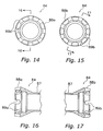
- the outer annular portion 24 basically includes a pair of annular side sections 28 and an annular outer bridge or connecting section 30 with a plurality of outer attachment openings 33.
- the annular connecting section 30 extends between the annular side sections 28 to form a substantially U-shaped tire receiving recess as seen in cross-section ( Figure 3). More specifically, the annular connecting section 30 is fixedly coupled to the annular side sections 28 at a radial position between the inner and outer ends of the annular side sections 28.
- the annular side sections 28 are annular plate shaped members that include annular tire supporting surfaces and annular braking surfaces in a conventional manner.
- the tire supporting surfaces are opposed annular surfaces with annular ribs that face each other toward the center plane P to retain beads of the tire 19 in a conventional manner.
- the annular braking surfaces face outwardly away from the center plane P to engage a conventional rim brakes.
- the annular side sections 28 are fixedly coupled to the inner annular portion 26, as explained below.
- the annular connecting section 30 is a stepped tubular member that includes a pair of annular sloping legs 32, a pair of annular parallel legs 34 and an outer annular attachment element 36.
- the sloping legs 32 extend axially toward each other and slope radially inwardly toward the center axis X as the legs 32 extend toward the center plane P.
- the parallel legs 34 are parallel to the center plane P and the braking surfaces.
- the outer attachment element 36 is preferably cylindrically shaped.
- the parallel legs 34 extend between the sloping legs 32 and the outer attachment element 36 to form a substantially U-shaped annular attachment channel.
- outer ends of the parallel legs 34 are fixedly coupled to the sloping legs 32, while inner ends of the parallel legs 34 are fixedly coupled to the outer attachment element 36.
- the outer attachment element 36 preferably has the outer attachment openings 33 formed therein.
- the outer attachment element 36 also preferably includes a single valve aperture 35 formed therein for coupling a valve 38 therein, as seen in Figures
- valve aperture 35 and the valve 38 can be designed for a tubeless tire in a conventional manner, and/or a tube-type tire in a conventional manner. In any case, because the valve 38 is conventional, the valve 38 will not be discussed and/or illustrated in detail herein.
- the outer attachment element 36 preferably has sixteen (16) of the outer attachment openings 33 formed therein.
- the outer attachment openings 33 are equally spaced apart in the circumferential direction to be compatible with the front hub 20 such that sixteen (16) of the spokes 14 extend between the hub 20 and the rim 16.
- the outer attachment openings 33 extend between an annular outwardly facing surface 36a and an annular inwardly facing surface 36b of the cylindrical outer attachment element 36.
- Each outer attachment opening 33 preferably extends in the radial direction, and is dimensioned to receive one of the reinforcement members 13 therein.
- the outwardly and inwardly facing surfaces 36a and 36b engage the reinforcement members 13, as discussed below.
- the outwardly and inwardly facing surfaces 36a and 36b can be considered first and second outer rim surfaces, respectively.
- the inner annular portion 26 is a tubular member that is substantially U-shaped.
- the inner annular portion 26 basically includes a pair of slanted sections 40, an inner attachment element section 42 fixedly coupled to the slanted sections 40 and a plurality of inner attachment openings 43.
- the slanted sections 40 extend axially toward each other, and slope radially inwardly toward center axis X as the slanted sections 40 extend toward the center plane P.
- Outer ends of the slanted sections 40 are fixedly coupled to inner ends of the annular side sections 28 of the outer annular portion 24. Inner ends of the slanted sections 40 are fixedly coupled to radially outer ends of the inner attachment element 42.
- the inner attachment element 42 forms a curved inner periphery of the rim 16.
- the inner attachment element 42 preferably has the plurality of inner attachment openings 43 formed therein.
- the inner attachment element 42 also preferably includes a single valve aperture 45 formed therein for coupling the valve 38 thereto, as seen in Figures 1 and 25.
- the inner attachment element 42 preferably has sixteen (16) of the inner attachment openings 43 formed therein.
- the inner attachment openings 43 are equally spaced apart in the circumferential direction, and radially aligned with the outer attachment openings 33 to be coupled with the front central hub 20 by the spokes 14.
- the inner attachment openings 43 extend between an annular outwardly facing surface 42a and an annular inwardly facing surface 42b of the inner attachment element 42.
- Each inner attachment opening 43 preferably extends in the radial direction and is dimensioned to receive one of the reinforcement members 13 therein.
- each inner attachment opening 43 is preferably spaced from and radially aligned with one of the outer attachment openings 33.
- the inner attachment openings 43 are preferably smaller than the outer attachment openings 33, as discussed in more detail below.
- the outwardly and inwardly facing surfaces 42a and 42b engage the reinforcement members 13, as discussed below.
- the outwardly and inwardly facing surfaces 42a and 42b can be considered first and second inner rim surfaces, respectively.
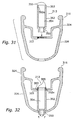
- each reinforcement member 13 is preferably constructed as a one-piece unitary member from a lightweight, rigid yet malleable metallic material.
- the reinforcement members 13 can be deformed when secured to the rim 16, and provide rigid reinforcement to the rim 16.
- each of the reinforcement members 13 has an original or pre-formed shape as shown in Figures 4, 5 and 8-10, and a deformed shape as seen in Figures 3, 6, 7 and 11. All of the reinforcement members 13 are preferably identical to each other. Thus, only one of the reinforcement members 13 will be discussed and/or illustrated in detail herein.
- each reinforcement member 13 is preferably a tubular step-shaped member having an inner or first tubular portion 50, an outer or second tubular portion 52 and a stepped interior passageway 54 extending through the first and second tubular portions 50 and 52, prior to deforming the reinforcement members 13 to fixedly couple the rim 16 thereto.
- each reinforcement member 13 has a circular shape as seen in the longitudinal direction ( Figure 9).
- the first and second tubular portions 50 and 52 preferably have constant, circular cross-sections, prior to deformation.
- the first tubular portion 50 includes a first free end 50a and a first attachment end 50b fixedly coupled to the second tubular portion 52.
- the first free end 50a forms part of a first or inner end of each reinforcement member 13.
- the second tubular portion 52 includes a second free end 52a and a second attachment end 52b fixedly coupled to the first attachment and 50b.
- the interior passageway 54 preferably includes an inner tubular section 54a formed at the interior of the first tubular portion 50 and an outer tubular section 54b formed at the interior of the second tubular portion 52.
- the inner tubular section 54a has a first maximum width W 1 and the outer tubular section 54b has a second maximum width W 2 larger than the first maximum width W 1 as seen in Figure 10. Because the reinforcement members 13 are preferably circular shaped, the maximum widths W 1 and W 2 are preferably maximum diameters.
- annular internal abutment surface 56 is preferably pre-formed between the first and second tubular portions 50 and 52 within the interior passageway 54 (i.e., between the inner and outer tubular sections 54a and 54b).
- the internal abutment surface 56 is designed to engage an enlarged head of one of the spokes 14, as discussed below.
- annular external abutment or retaining surface 58 is preferably pre-formed between the first and second tubular portions 50 and 52.
- the external retaining surface 58 is designed to engage the inner attachment element 42 of the rim 16.
- the external retaining surface 58 is designed to contact/engage the outwardly facing surface 42a of the inner attachment element 42 of the rim 16.
- the first tubular portion 50 is sized to be slidably received in one of the inner attachment openings 43, while the second tubular portion 52 is sized to be slidably received in one of the outer attachment openings 33, as seen in Figures 4 and 5. Since the first tubular portion 50 is smaller than the second tubular portion 52, the first tubular portion 50 is also easily received through one of the outer attachment openings 33.
- the first tubular portion 50 and the retaining surface 58 form an inner end of the reinforcement member 13, while the second free end 52a of the second tubular portion 52 forms an outer end of the reinforcement member 13.
- each reinforcement member 13 is positioned in the outer and inner attachment openings 33 and 43 ( Figure 5), the reinforcement member 13 is deformed to permanently secure the reinforcement member 13 to the rim 16, as seen in Figures 3, 6, 7 and 11.
- the structure of the reinforcement members 13 after deformation will now be discussed in more detail.
- each reinforcement member 13 still includes the first tubular portion 50, the second tubular portion 52 and the interior passageway 54, but with modified/deformed shapes.
- the first and second tubular portions 50 and 52 do not have constant cross-sections after deformation.
- the first and second tubular portions 50 and 52 are still circular-shaped after deformation.
- a section of the interior passageway 54 is preferably enlarged/expanded using a mandrel, and the first and second free ends 50a and 52a are preferably deformed by riveting to deform the reinforcement members 13 into the shape illustrated in Figures 3, 6, 7 and 11.
- part of the outer tubular section 54b of the interior passageway 54 is preferably enlarged/expanded adjacent the second free end 52a to create an additional internal abutment surface 54c.
- the additional annular internal abutment is designed to engage an optional seal member 60, illustrated in Figure 3 and discussed below.
- a seal member 60 is mounted in each of the reinforcement members 13. If a tube-type tire is used, the seal members 60 are not necessary.
- the shapes of the attachment ends 50b and 52b of the first and second tubular portions 50 and 52 do not change during deformation.
- the internal abutment surface 56 and the retaining surface 58 preferably have the same sizes/shapes before and after deformation of the reinforcement member 13.
- much of the interior passageway 54 has the same size/and shape before and after deformation of the reinforcement member 13.
- each reinforcement member 13 includes several additional external abutment or retaining surfaces after deformation. Specifically, each reinforcement member 13 includes an inner retaining surface 62a, and a pair of outer retaining surface 62b and 62c. Because the retaining surfaces 62a, 62b and 62c are created during the deformation of the reinforcement members 13 onto the rim 16, these retaining surfaces 62a, 62b and 62c are considered deformed surfaces. Each reinforcement member 13 also includes the pre-formed retaining surface 58, which is not created during the deformation of the reinforcement members 13 onto the rim 16. Thus, term "pre-formed” as used herein refers to deformation occurring prior to the attachment process of securing the reinforcement members 13 to the rim 16.
- deformed refers to deformation occurring during the attachment process of securing the reinforcement members 13 to the rim 16.
- retaining surfaces 58, 62a, 62b and 62c of each reinforcement members 13 secure/retain the inner and outer ends of the reinforcement members 13 against inward and outward radial movement after deformation of the reinforcement members 13.
- the retaining surface 58 faces radially inwardly to contact the outwardly facing surface 42a of the inner attachment element 42, while the retaining surface 62a faces radially outwardly to contact the inwardly facing surface 42b of the inner attachment element 42.
- the retaining surface 58 can be considered a first inner retaining surface, while the retaining surface 62a can be considered a second inner retaining surface.
- the retaining surface 62c faces radially inwardly to contact the outwardly facing surface 36a of the outer attachment element 36, while the retaining surface 62b faces radially outwardly to contact the inwardly facing surface 36b of the outer attachment element 36.
- the retaining surface 62c can be considered a first outer retaining surface, while the retaining surface 62b can be considered a second outer retaining surface.
- the retaining surface 58, the outwardly facing surface 42a of the inner attachment element 42, the retaining surface 62a and the inwardly facing surface 42b of the inner attachment element 42 form an inner connection between each reinforcement member 13 and the rim 16.
- the inner connection prevents inward and outward movement of the inner end of each reinforcement member 13 relative to the inner annular portion 26 of the rim 16.
- the retaining surface 62c, the outwardly facing surface 36a of the outer attachment element 36, the retaining surface 62b and the inwardly facing surface 36b of the outer attachment element 36 form an outer connection between each reinforcement member 13 and the rim 16.
- the outer connection prevents inward and outward movement of the outer end of each reinforcement member 13 relative to the outer annular portion 24 of the rim 16.
- each interior passageway 54 with the internal abutment surface 56 of each of the reinforcement members 13 is designed to retain an outer end of one of the spokes 14 therein.
- each interior passageway 54 extends in the radial direction, but is large enough such that the spoke 14 mounted therein can be slightly angled relative to the center plane P, i.e., to extend to one side of the hub 20.
- the spokes 14 are preferably identical to each other.
- Each of the spokes 14 basically includes an outer end portion 64, a center or a middle portion 66, an inner end portion 68 and a spoke nipple 70.
- the outer end portion 64, the center portion 66, and the inner end portion 68 of each spoke 14 are preferably integrally formed together as a one piece, unitary member.
- the spoke nipples 70 are preferably formed as separate members.
- Each of the outer end portions 64 of the spokes 14 has an enlarged head 72 designed to engage one of the internal abutment surfaces 56 of one of the reinforcement members 13, while each of the inner end portions 68 of the spokes 14 preferably has external threads with one of the spoke nipples 70 threadedly coupled thereto.
- the spokes 14 are placed under tension between the hub 20 and the annular rim 16 by rotating the spoke nipples in a conventional manner.
- the spokes 14 are preferably conventional wire-type spokes. Thus, the spokes 14 will not be discussed and/or illustrated in detail herein except as related to the rim 16 of the present invention.
- connections of the spokes 14 to the hubs 20 and 22 will now be discussed in more detail.
- the connections of the spokes 14 to the hubs 20 and 22 are basically identical to the connections disclosed in U.S. Patent No. 6,431,658, except as explained below.
- the hubs 20 and 22 are slightly modified versions of the front and rear hubs disclosed in U.S. Patent No. 6,431,658, which are designed to be used with the rims 16 and 18 having circumferentially equally spaced spoke attachment points.
- the front hub 20 basically includes a tubular hub body portion 84, first and second bearing assemblies 85a and 85b, and a hub axle 86 rotatably supported in tubular body portion 84 by the bearing assemblies 85a and 85b.
- the parts of the front hub 20 are relatively conventional. Thus, the parts of the front hub 20 will not be discussed or illustrated in detail herein.
- the tubular body portion 84 has a tubular center portion 87 and a pair of tubular mounting portions 88a and 88b at opposite ends of the center portion 87 for mounting the spokes 14 thereto.
- Each tubular mounting portion 88a and 88b has a plurality of spoke openings 89a and 89b for coupling the spokes 14 therein, respectively.
- each mounting portion 88a and 88b has eight spoke openings 89a and 89b formed therein, respectively.
- the second mounting portion 88b is an offset mirror image of first mounting portion 88a.
- the spoke openings 89b are preferably circumferentially offset from the spoke openings 89a so that the outer end portions 64 of the spokes 14 are circumferentially equally spaced from each other at the rim 16.
- the tubular mounting portions 88a and 88b support the spokes 14 in spoke openings 89a and 89b with the spoke nipples 70.
- the rear hub 22 basically includes a tubular hub body portion 92, a bearing support sleeve 93, a first bearing assembly 94a, a second bearing assembly 94b, a freewheel mounting portion 95 and a hub axle 96.
- the hub axle 96 is rotatably supported in the tubular body portion 92 by the bearing assemblies 94a and 94b.
- the freewheel mounting portion 95 is coupled to the body portion 92 in a conventional manner and has a plurality of splines for receiving a freewheel (not shown).
- the parts of the rear hub 22 are relatively conventional. Thus, the parts of the rear hub 22 will not be discussed and/or illustrated in detail herein.
- the tubular body portion 92 has a tubular center portion 97 and a pair of tubular mounting portions 98a and 98b fixedly coupled to opposite ends of the center portion 97 for mounting the spokes 14 thereto.
- the second mounting portion 98b is different from the first mounting portion 98a so that a freewheel (not shown) can be coupled to the rear hub 22.
- Each tubular mounting portion 98a and 98b has a plurality of spoke openings 99a and 99b for coupling the spokes 14 thereto.
- each mounting portion 98a and 98b has eight of the spoke openings 99a and 99b formed therein, respectively.
- the tubular mounting portions 98a and 98b support a plurality of spokes 14 in the spoke openings 99a and 99b by the spoke nipples 70.
- the first mounting portion 98a is identical to the first mounting portion 88a of the front hub 20, except that first mounting portion 98a has larger inner and outer diameters than the first mounting portion 88a.
- the mounting portion 98b is formed of a plurality of spoke attachment projections 100 and a tapered portion.
- the second mounting portion 98b is arranged on an opposite side of center portion 97 from the first mounting portion 98a.
- the mounting portion 98b has four spoke attachment projections 100 with a pair of opposing closed spoke openings 99b formed in each spoke attachment projection 100 for attaching eight of the spokes 14 thereto.
- the spoke attachment projections 100 are preferably circumferentially aligned with alternating spoke openings 99a of the first mounting portion 98a to provide the proper spoking arrangement.
- the rim 18 of the rear wheel 12 is identical to the rim 16 of the front wheel 10, even though some of the spokes 14 of the rear wheel 12 are arranged at slightly different angles than the spokes 14 of the front wheel 10.
- the configuration of each reinforcement members 13 allows the spokes 14 to be angled slightly to attach to opposite sides of the hub 20 or 22 tangentially or radially.
- the material of the outer and inner annular portions 24 and 26 is preferably extruded through a die to form an elongated strip of the rim material using conventional manufacturing techniques.
- the rim material is preferably extruded in the overall cross-sectional shape of the outer and inner annular portions 24 and 26.
- the elongated strip of rim material is then cut to the desired length and shaped into an annulus.
- the ends of cut strip of rim material are then bonded together by welding or any suitable manufacturing technique to create a continuous annular-shaped rim.
- the outer and inner attachment holes 33 and 43 are preferably formed in the rim material by drilling or punching. The holes can be formed anytime after the rim material is extruded as needed and/or desired.
- the reinforcement members 13 are preferably formed separately by casting or any suitable manufacturing technique.
- the reinforcement members 13 are preferably mounted in the attachment holes 33 and 43 after the ends of the rim strip material are bonded together.
- the reinforcement members 13 are then deformed to permanently secure the reinforcement members 13 to the outer and inner annular portion 24 and 26.
- the reinforcement members 13 are deformed using a mandrel and riveting, as mentioned above.
- the rim 18 is made in a manner identical to the rim 16. The preferred forces exerted on the reinforcement members 13 are illustrated with arrows in the drawings.
- a modified bicycle rim 216 is illustrated in accordance with a second embodiment of the present invention.
- the rim 216 is identical to the rim 16 of the first embodiment, except that the rim 216 utilizes a plurality of modified reinforcement members 213 (only one shown).
- each of the reinforcement members 213 has a modified shape prior to deformation.
- the rim 216 is made using a method identical to the first embodiment, and the reinforcement members 213 have a deformed shape identical to the deformed shape of the reinforcement members 13 of the first embodiment.
- the rim 216 and the method of making the rim 216 will not be discussed and/or illustrated in detail herein. Rather, the following description will focus mainly on the differences.
- the rim 216 includes a plurality of reinforcement members 213. Moreover, it will be apparent to those skilled in the art from this disclosure that the descriptions and/or illustrations of the rim 16 with the reinforcement members 13 of the first embodiment also apply to this second embodiment, except as explained below. It will also be apparent to those skilled in the art from this disclosure that the optional seal members 60 can be used with this arrangement, if a tubeless tire is desired.
- the rim 216 is designed to be used with either of the hubs 20 or 22.
- Each reinforcement member 213 is identical to the reinforcement members 13 of the first embodiment after deformation of the reinforcement members 213.
- the descriptions and illustrations of the deformed reinforcement members 13 also apply to the deformed reinforcement members 213 of this second embodiment.
- the deformed reinforcement members 213 will not be discussed and or illustrated in detail herein.
- the reinforcement members 213 have a modified shape prior to deformation, as mentioned above.
- each of the reinforcement members 213 is preferably a tubular step-shaped member having a pair of first tubular portions 250, a second tubular portion 252 and a stepped interior passageway 254 extending through the first and second tubular portions 250 and 252, prior to deforming the reinforcement members 213.
- Each of the first tubular portions 250 is identical to the first (inner) tubular portion 50 of the first embodiment.
- the second tubular portion 252 is identical to the second (outer) tubular portion 52 of the first embodiment except the second tubular portion 252 is shorter, due to the presence of two (2) first tubular portions 250.
- two internal abutment surfaces 256 are formed between a pair of first tubular sections 254a and a second tubular section 254b of the internal passageway 254.
- two external retaining surfaces 258 are formed between the first tubular portions 250 and the second tubular portion 252 prior to deformation.
- the internal abutment surfaces 256 are identical to the internal abutment surface 56 of the first embodiment.
- the external retaining surfaces 258 are also identical to the external retaining surface 58 of the first embodiment.
- the first tubular portions 250 form the inner/outer ends of the reinforcement members 213 prior to deformation such that either end can be the radially inner end.
- each reinforcement member 213 has a circular shape.
- each of the first and second tubular portions 250 and 252 preferably has constant, circular cross-sections, prior to deformation.
- a modified bicycle rim 316 is illustrated in accordance with a third embodiment of the present invention.
- the rim 316 is identical to the rim 16 of the first embodiment, except that the rim 316 utilizes a modified outer annular portion 324 and a plurality of modified reinforcement members 313 (only one shown) with threaded outer ends.
- each of the reinforcement members 313 has a modified shape prior to deformation.
- the rim 316 is made using a modified version of the method used to make the rim 16 of the first embodiment.
- the reinforcement members 313 also have modified deformed shapes.
- the reinforcement members 313 function in a manner very similar to the reinforcement members 13 of the first embodiment.
- the rim 316 and the method of making the rim 316 will not be discussed and/or illustrated in detail herein. Rather, the following description will focus mainly on the differences.
- the rim 316 includes a plurality of reinforcement members 313. Moreover, it will be apparent to those skilled in the art from this disclosure that the descriptions and/or illustrations of the rim 16 with the reinforcement members 13 of the first embodiment also apply to this third embodiment, except as explained below. It will also be apparent to those skilled in the art from this disclosure that the optional seal members 60 can be used with this arrangement, if a tubeless tire is desired.
- the rim 316 is designed to be used with either of the hubs 20 or 22.
- Each reinforcement member 313 is preferably a tubular step-shaped member having a first tubular portions 350, a second tubular portion 352 and a stepped interior passageway 354 extending through the first and second tubular portions 350 and 352, prior to deforming the reinforcement members 313.
- the first tubular portion 350 is identical to the first (inner) tubular portion 50 of the first embodiment.
- the second tubular portion 352 is identical to the second (outer) tubular portion 52 of the first embodiment, except that the second tubular portion 352 includes external threads 353 and a pair of slots 355 formed in a free end 352a thereof. Also, the second tubular portion 352 is slightly shorter than the second tubular portion 52 of the first embodiment.
- each reinforcement member 313 are designed to engage a conventional flat head screwdriver to rotate each of the reinforcement members 313.
- the outer annular portion 324 of the rim 316 is a modified version of the outer annular portion 24 of the first embodiment.
- the rim 316 basically includes the modified outer annular portion 324, an inner annular portion 326 and a plurality of the reinforcement members 313.
- the inner annular portion 326 is identical to the inner annular portion 26 of the first embodiment.
- the outer annular portion 324 includes a plurality of modified outer attachment openings 333 designed to threadedly engage the external threads 353 of the reinforcement members. Otherwise, the outer annular portion 324 is identical to the outer annular portion 24 of the first embodiment.
- the outer attachment openings 333 are identical to the outer attachment openings 33 of the first embodiment except the outer attachment openings 333 are threaded. In other words, the outer attachment openings 333 are preferably circumferentially equally spaced from each other, etc.
- the rim 316 is made using a method identical to the first embodiment except the reinforcement members 313 are fixedly coupled to the outer annular portion 324 via a threaded outer connection by rotating the reinforcement members. The outer ends of the reinforcement members 313 are not deformed when making the rim 316 of this third embodiment.
- the rim 16 illustrated with an alternate, reversed spoking arrangement in accordance with the present invention.
- the spokes 14 are reversed so as to be compatible with front and/or rear hubs (not shown) different from the hubs 20 and 22.
- the spoke nipples 70 are coupled to the reinforcement members 13.
- the reversed spokes 14 could be modified as needed and/or desired, depending on the type of hub used.
- the optional seal members 60 can be used with this arrangement, if a tubeless tire is desired.
Landscapes
- Engineering & Computer Science (AREA)
- Mechanical Engineering (AREA)
- Tires In General (AREA)
Applications Claiming Priority (2)
| Application Number | Priority Date | Filing Date | Title |
|---|---|---|---|
| US319693 | 2002-12-16 | ||
| US10/319,693 US6736462B1 (en) | 2002-12-16 | 2002-12-16 | Bicycle rim |
Publications (2)
| Publication Number | Publication Date |
|---|---|
| EP1431069A2 true EP1431069A2 (de) | 2004-06-23 |
| EP1431069A3 EP1431069A3 (de) | 2005-06-08 |
Family
ID=32298108
Family Applications (1)
| Application Number | Title | Priority Date | Filing Date |
|---|---|---|---|
| EP03029029A Withdrawn EP1431069A3 (de) | 2002-12-16 | 2003-12-16 | Fahrradfelge |
Country Status (5)
| Country | Link |
|---|---|
| US (1) | US6736462B1 (de) |
| EP (1) | EP1431069A3 (de) |
| JP (1) | JP3746054B2 (de) |
| CN (1) | CN1511718A (de) |
| TW (1) | TWI231277B (de) |
Cited By (2)
| Publication number | Priority date | Publication date | Assignee | Title |
|---|---|---|---|---|
| EP1502768A3 (de) * | 2003-08-01 | 2005-09-07 | Shimano Inc. | Fahrradfelge |
| DE102024117759A1 (de) * | 2024-06-24 | 2025-12-24 | Carbovation Gmbh | Fahrradfelge mit Rippenbauteil beabstandet zu Felgenwänden, Laufrad und Herstellverfahren für Laufrad |
Families Citing this family (22)
| Publication number | Priority date | Publication date | Assignee | Title |
|---|---|---|---|---|
| US7192098B2 (en) * | 2003-05-07 | 2007-03-20 | Shimano Inc. | Bicycle rim |
| US20050194834A1 (en) * | 2004-03-03 | 2005-09-08 | Chun-Hsung Chen | Bicycle spoke fixture assembly |
| ITBO20040448A1 (it) * | 2004-07-19 | 2004-10-19 | Ba S R L Fa | Ruota a raggi con cerchio per l'adozione di pneumatico tubeless, particolarmente per motocicli ed automobili |
| US7334846B2 (en) | 2004-10-06 | 2008-02-26 | Koziatek Stanley F | Bicycle wheel rim |
| FR2882687B1 (fr) * | 2005-03-03 | 2008-09-26 | Rigida Soc Par Actions Simplif | Dispositif de renforcement de jantes de bicyclettes et roues comprenant une telle jante |
| US7431404B2 (en) * | 2005-08-05 | 2008-10-07 | Shimano Inc. | Bicycle having annular sealing member |
| ITPD20050271A1 (it) * | 2005-09-21 | 2007-03-22 | Alpina Raggi Spa | Metodo per la fabbricazione di una ruota a raggi e ruota ottenuta con tale metodo |
| DE102005049764A1 (de) * | 2005-10-18 | 2007-04-26 | Schürmann Fahrradteile GmbH & Co. KG | Öse für eine Hohlkammerfelge |
| US7331639B2 (en) * | 2005-11-04 | 2008-02-19 | Shimano Inc. | Bicycle rim |
| ITMI20061401A1 (it) * | 2006-07-19 | 2008-01-20 | Ruotemilano S R L | Dispositivo per fissare un raggio al cerchione di una ruota a raggi |
| ES2364084T3 (es) * | 2006-12-29 | 2011-08-24 | Rodi - Metalúrgicas Do Eixo, S.A. | Rueda de bicicleta con llanta para un neumático sin cámara. |
| WO2009036491A1 (en) * | 2007-09-17 | 2009-03-26 | Damien Joseph Mangion-Campbell | Stud |
| TWI386321B (zh) * | 2009-02-20 | 2013-02-21 | Gigantex Composite Technologies Co Ltd | Combination of rim and spoke |
| NL2004125C2 (en) * | 2010-01-21 | 2011-07-25 | 3T Design Ltd | A bicycle wheel rim having sidewardly opening two-part slit shaped spoke mounting apertures. |
| CN201646244U (zh) * | 2010-05-13 | 2010-11-24 | 王景山 | 结构改进的碳纤维轮圈 |
| TW201204574A (en) * | 2010-07-22 | 2012-02-01 | jing-shan Wang | Bicycle wheel rim |
| US9481202B2 (en) * | 2014-01-31 | 2016-11-01 | Specialized Bicycle Components, Inc. | Plug for a tubeless bicycle wheel |
| JP2017178215A (ja) * | 2016-03-31 | 2017-10-05 | 本田技研工業株式会社 | チューブレススポークホイールの構造 |
| TWI615290B (zh) * | 2016-08-30 | 2018-02-21 | 亞獵士科技股份有限公司 | 碳纖維輪圈強化結構 |
| CN108754589B (zh) * | 2018-07-10 | 2023-11-07 | 浙江师范大学 | 辐条穿插装置 |
| JP7121716B2 (ja) * | 2019-09-27 | 2022-08-18 | 本田技研工業株式会社 | チューブレスワイヤスポークホイール及びリム |
| US20230322018A1 (en) * | 2022-04-11 | 2023-10-12 | DNA Specialty | Self-sealing Automotive Spoke Wheel Nipple |
Citations (1)
| Publication number | Priority date | Publication date | Assignee | Title |
|---|---|---|---|---|
| US6431658B1 (en) | 2000-03-17 | 2002-08-13 | Shimano Inc. | Bicycle hub |
Family Cites Families (11)
| Publication number | Priority date | Publication date | Assignee | Title |
|---|---|---|---|---|
| US1280646A (en) * | 1917-09-22 | 1918-10-08 | Frederick H Billhartz | Spoke remover and tightener. |
| FR1498599A (fr) * | 1966-09-02 | 1967-10-20 | Metallurg Du Rhone Ets | Oeillet pour jantes tubulaires de roues de bicyclette ou autres similaires |
| IT1163595B (it) * | 1983-06-24 | 1987-04-08 | Campagnolo Spa | Boccole inclinate per cerchi di ruote di biciclette e cerchi con esse realizzati |
| FR2727356A1 (fr) * | 1994-11-30 | 1996-05-31 | Mavic Sa | Jante de velo et roue comprenant une telle jante |
| FR2727652A1 (fr) | 1994-12-02 | 1996-06-07 | Mavic Sa | Jante pour cycle munie d'elements de guidage d'ecrous |
| FR2750913B1 (fr) * | 1996-07-12 | 1998-10-09 | Mavic Sa | Procede de percage d'une jante a rayon, jante percee selon le procede, insert adapte pour equiper la jante, et roue notamment de cycle |
| US6216344B1 (en) | 1996-07-12 | 2001-04-17 | Mavic S.A. | Method for boring a spoke rim and for providing an insert for the bored rim |
| US5806935A (en) | 1996-12-30 | 1998-09-15 | Shermeister; Chris J. | Tension-lock system for spokes in spoked wheels |
| US6145937A (en) * | 1999-07-13 | 2000-11-14 | Alex Machine Industrial Co., Ltd. | Bicycle wheel rim |
| IT1320582B1 (it) | 2000-08-03 | 2003-12-10 | Campagnolo Srl | Cerchio per una ruota di bicicletta con pneumatico senza camera d'aria. |
| JP3973842B2 (ja) * | 2001-02-06 | 2007-09-12 | 大同工業株式会社 | チューブレスタイヤ用のワイヤースポークホイール |
-
2002
- 2002-12-16 US US10/319,693 patent/US6736462B1/en not_active Expired - Fee Related
-
2003
- 2003-11-26 TW TW092133172A patent/TWI231277B/zh not_active IP Right Cessation
- 2003-12-12 JP JP2003415342A patent/JP3746054B2/ja not_active Expired - Fee Related
- 2003-12-15 CN CNA2003101205941A patent/CN1511718A/zh active Pending
- 2003-12-16 EP EP03029029A patent/EP1431069A3/de not_active Withdrawn
Patent Citations (1)
| Publication number | Priority date | Publication date | Assignee | Title |
|---|---|---|---|---|
| US6431658B1 (en) | 2000-03-17 | 2002-08-13 | Shimano Inc. | Bicycle hub |
Cited By (2)
| Publication number | Priority date | Publication date | Assignee | Title |
|---|---|---|---|---|
| EP1502768A3 (de) * | 2003-08-01 | 2005-09-07 | Shimano Inc. | Fahrradfelge |
| DE102024117759A1 (de) * | 2024-06-24 | 2025-12-24 | Carbovation Gmbh | Fahrradfelge mit Rippenbauteil beabstandet zu Felgenwänden, Laufrad und Herstellverfahren für Laufrad |
Also Published As
| Publication number | Publication date |
|---|---|
| CN1511718A (zh) | 2004-07-14 |
| JP2004196288A (ja) | 2004-07-15 |
| TW200420447A (en) | 2004-10-16 |
| US6736462B1 (en) | 2004-05-18 |
| JP3746054B2 (ja) | 2006-02-15 |
| EP1431069A3 (de) | 2005-06-08 |
| TWI231277B (en) | 2005-04-21 |
Similar Documents
| Publication | Publication Date | Title |
|---|---|---|
| US6736462B1 (en) | Bicycle rim | |
| US7083239B2 (en) | Bicycle rim | |
| US6409282B1 (en) | Bicycle hub | |
| EP1016553B1 (de) | Fahrradrad | |
| US6536849B1 (en) | Bicycle wheel | |
| EP1726457B1 (de) | Fahrradnabe | |
| US6679563B2 (en) | Bicycle wheel | |
| EP1316442B1 (de) | Fahrradfelge | |
| EP1236586A2 (de) | Fahrradfelge | |
| US20050023883A1 (en) | Bicycle rim | |
| US7360847B2 (en) | Bicycle hub | |
| EP1486352B1 (de) | Fahrradfelge | |
| US6485108B1 (en) | Bicycle hub | |
| EP1475245B1 (de) | Fahrradfelge |
Legal Events
| Date | Code | Title | Description |
|---|---|---|---|
| PUAI | Public reference made under article 153(3) epc to a published international application that has entered the european phase |
Free format text: ORIGINAL CODE: 0009012 |
|
| AK | Designated contracting states |
Kind code of ref document: A2 Designated state(s): AT BE BG CH CY CZ DE DK EE ES FI FR GB GR HU IE IT LI LU MC NL PT RO SE SI SK TR |
|
| AX | Request for extension of the european patent |
Extension state: AL LT LV MK |
|
| PUAL | Search report despatched |
Free format text: ORIGINAL CODE: 0009013 |
|
| AK | Designated contracting states |
Kind code of ref document: A3 Designated state(s): AT BE BG CH CY CZ DE DK EE ES FI FR GB GR HU IE IT LI LU MC NL PT RO SE SI SK TR |
|
| AX | Request for extension of the european patent |
Extension state: AL LT LV MK |
|
| 17P | Request for examination filed |
Effective date: 20050523 |
|
| AKX | Designation fees paid |
Designated state(s): AT BE BG CH CY CZ DE DK EE ES FI FR GB GR HU IE IT LI LU MC NL PT RO SE SI SK TR |
|
| RAP1 | Party data changed (applicant data changed or rights of an application transferred) |
Owner name: SHIMANO INC. |
|
| 17Q | First examination report despatched |
Effective date: 20070518 |
|
| STAA | Information on the status of an ep patent application or granted ep patent |
Free format text: STATUS: THE APPLICATION HAS BEEN WITHDRAWN |
|
| 18W | Application withdrawn |
Effective date: 20070911 |