EP1431013A2 - Tischkreissägemaschine - Google Patents
Tischkreissägemaschine Download PDFInfo
- Publication number
- EP1431013A2 EP1431013A2 EP03023455A EP03023455A EP1431013A2 EP 1431013 A2 EP1431013 A2 EP 1431013A2 EP 03023455 A EP03023455 A EP 03023455A EP 03023455 A EP03023455 A EP 03023455A EP 1431013 A2 EP1431013 A2 EP 1431013A2
- Authority
- EP
- European Patent Office
- Prior art keywords
- riving knife
- guide
- saw
- knife holder
- tool carrier
- Prior art date
- Legal status (The legal status is an assumption and is not a legal conclusion. Google has not performed a legal analysis and makes no representation as to the accuracy of the status listed.)
- Granted
Links
Images

Classifications
-
- B—PERFORMING OPERATIONS; TRANSPORTING
- B27—WORKING OR PRESERVING WOOD OR SIMILAR MATERIAL; NAILING OR STAPLING MACHINES IN GENERAL
- B27G—ACCESSORY MACHINES OR APPARATUS FOR WORKING WOOD OR SIMILAR MATERIALS; TOOLS FOR WORKING WOOD OR SIMILAR MATERIALS; SAFETY DEVICES FOR WOOD WORKING MACHINES OR TOOLS
- B27G19/00—Safety guards or devices specially adapted for wood saws; Auxiliary devices facilitating proper operation of wood saws
- B27G19/02—Safety guards or devices specially adapted for wood saws; Auxiliary devices facilitating proper operation of wood saws for circular saws
-
- B—PERFORMING OPERATIONS; TRANSPORTING
- B27—WORKING OR PRESERVING WOOD OR SIMILAR MATERIAL; NAILING OR STAPLING MACHINES IN GENERAL
- B27G—ACCESSORY MACHINES OR APPARATUS FOR WORKING WOOD OR SIMILAR MATERIALS; TOOLS FOR WORKING WOOD OR SIMILAR MATERIALS; SAFETY DEVICES FOR WOOD WORKING MACHINES OR TOOLS
- B27G19/00—Safety guards or devices specially adapted for wood saws; Auxiliary devices facilitating proper operation of wood saws
- B27G19/08—Accessories for keeping open the saw kerf, e.g. riving knives or wedge plates
Definitions
- the invention relates to a Tischniksägemaschine with the features of Preamble of claim 1.
- a table saw machine has a saw table with workpiece support and support frame on. Under the workpiece support is located in a housing a sawing unit with a tool carrier, on which a circular saw blade is clamped or can be clamped.
- the circular saw blade passes through the workpiece support surface in a shegeschlitz, so protrudes above the workpiece support surface beyond.
- the tool carrier with the attached circular saw blade, if necessary, the saw unit together with Tool carrier and circular saw blade is opposite the workpiece support surface adjustable in height, by means of a usually manually adjustable height adjustment. As a result, the depth of cut in the workpiece can be adjusted.
- the Workpiece, z. B. a wooden plate is the for the respective operation in the height adjusted circular saw blade lying on the workpiece support surface usually supplied by hand.
- a table saw must be used to avoid workpiece kickbacks and an associated jamming of the circular saw blade with a Splitting wedge be equipped.
- This riving knife is, in the feed direction of Viewed workpiece, arranged behind the circular saw blade in the saw blade plane and thus prevents contact of those generated by sawing Cutting edges of the workpiece.
- a riving knife which is fixed over a riving knife holder, must, like the Splitting wedge holder, meet various requirements. So must the riving knife always kept exactly in the saw blade plane by the riving knife holder become. In addition, the distance of the riving knife from the circular saw blade during Sawing process remain constant and may usually not more than 10 mm. Furthermore, the highest point of the riving knife must not be lower than the tooth base of the uppermost tooth of the circular saw blade lie. Become Circular saw blades with different diameters spanned so can via an adjustment on the riving knife holder of the riving knife horizontally and be moved vertically in the saw blade plane. Possibly is also a pivoting possible. In particular, the riving knife must be his Relative position to the circular saw blade even with a height adjustment of the circular saw blade maintained ("Safety Rules for Table and Slicers," Holz-Berufspatenschaft ZH1 / 3.3).
- the safety rules for table saw machines are protective against touching the circular saw blade above the workpiece support.
- the part of the sprocket of the circular saw blade required for cutting must be secured against contact by an upper cover (protective hood) become.
- Such upper occlusion may be under certain conditions be attached to the riving knife (see the aforementioned safety rules).
- the force acting on the riving knife forces can cause the Splitting wedge moved out of the saw blade plane. Then the riving knife meets not or only limited its function. To counteract these influences Although you can increase the thickness of the splitting wedge, this However, this is dependent on the thickness of the circular saw blade dependent joint width limited.
- the teaching is based on the problem of a Tischniksägemaschine the in Speech standing way to design and further develop that the riving knife is guided with increased stability.
- the present invention solves the above problem in a Table saw with the features of the preamble of claim 1 by the features of the characterizing part of claim 1.
- Preferred Embodiments and developments are the subject of the dependent claims.
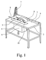
- Fig. 1 shows a Tischniksägemaschine as in the prior art is known. It may be repeated that the term table saw machine in the sense of the teaching of the present invention also Formatniksägemaschinen and multi-functional machines, the table circular saw function to have.
- FIG. 1 The table saw machine shown in Fig. 1 is now in connection of Fig. 1 and Fig. 2 will be explained.
- a workpiece support 1 is located on a saw table 2.
- this sawing unit is arranged, which in Fig. 1 is below the workpiece support 1 and therefore is not visible.
- this Sawing unit is associated with a tool carrier 3, shown in Fig. 2, on which a circular saw blade 4, recognizable in Fig. 1, can be attached.
- Fig. 2 is the circular saw blade 4 removed, so not clamped on the tool carrier 3, around the essential for the invention parts of the table saw machine not to obscure.
- Fig. 1 shows that the circular saw blade 4 up over the workpiece support. 1 protrudes by a small amount.
- the height at which the circular saw blade 4 is set is, is adjustable. The height adjustment is usually under the workpiece support 1, it is hidden in Fig. 1 and not visible.
- the circular saw blade 4 is associated with a riving knife 5, which in the feed direction S is arranged for a workpiece behind the circular saw blade 4.
- the function of the riving knife 5 has been explained in the general part of the description.
- the riving knife 5 serves in the illustrated embodiment simultaneously as Carrier for an upper covering of the circular saw blade 4 gear rim, for a protective cover 6.
- the suction hose 7 at the Protective hood 6 is attached.
- Fig. 1 can be seen on the workpiece support 1 of the saw table 2 still one Rip fence 9, on which a workpiece side-fitting in the feed direction S can be moved. Furthermore, one recognizes a kerf 10, in which the circular saw blade 4 passes through the workpiece support 1 from below.
- a housing 8 in which the saw unit, the tool carrier 3 and the circular saw blade 4, insofar as it does not protrude beyond the workpiece support 1, are.
- This housing 8 is opened in Fig. 2, one looks from the left in Fig. 1 in the interior of the housing 8 inside.
- a riving knife holder 11 at the attached to the riving knife 5 and with the riving knife 5 together with the Tool carrier 3 is height adjustable.
- the riving knife holder 11 is on or near the tool carrier 3 on the saw table 2, more precisely on the housing 8 height adjustable attached.
- the riving knife 5 can not only in height be adjusted, but also horizontally, so at different Diameters of the circular saw blade 4 can be used.
- the carrier screws 13 together with the plate of the housing 8 on the saw table 2 and the adjustment slot 12 in the riving knife holder 11 thus form one here in the essentially vertically erected adjustment guide.
- this first substantially vertical guide is now the invention provided second guide means 14.
- the riving knife holder 11 realizes a two-point control.
- this guide device 14 constructed in the illustrated embodiment, that the riving knife holder 11 is an edge-side guide rail 15th and that the guide means 14 at least one on the saw table 2 fixed guide angle 14 '; 14 ", in which the guide rail 15 at height adjustment of the riving knife holder 11 guided laterally shifts.
- a kinematic reversal of the above-described construction is so possible that the riving knife holder at the edge at least one guide angle and that the guide means attached to a saw table Guide rail, on which the guide angle at height adjustment the riving knife holder moves laterally guided.
- the guide device 14 two spaced apart, substantially the same effect Guide angle 14 '; 14 "in the illustrated embodiment the guide angles 14 ', 14 "comprise the guide rail 15 of the riving knife holder 11 laterally fork-shaped, so that the riving knife holder 11 really guided in a sliding guide on both sides.
- slip aids for example, rolls or plastic inserts.
- the term of the guide angle means otherwise only a certain terminology.
- the guide angle does not have to be mandatory it could also be in the form of a block, for example one Plastic blocks have. It is essential that the necessary lateral guidance the riving knife holder 11 results.
- the illustrated and preferred embodiment shows otherwise in particular constructive design further, that the riving knife holder 11 a Sullivannverstellbpar carrier 16 and a side-adjustable on the carrier 16 Has support plate 17 for the riving knife 5.
- the support plate 17 on the plate-like, height-adjustable Carrier 16 in turn in a substantially horizontal lying Adjustment slot 18 is adjustable.
- Fixation screws 19 are provided to fix the support plate 17, then to the the riving knife 5 itself is attached, in the adjustment slot 18 corresponding Fixation screws 19 are provided.
- a middle trunnion 20 for the Splitting wedge 5 together with fixing points 21 an additional adjustment for the riving knife 5.
- the illustrated and preferred embodiment shows, moreover, that the carrier 16 in the region between the guide means 14 and the Tool carrier 3 has a step 22, such that in the mounted state the riving knife 5 and the circular saw blade 4 lie in one plane.
- the illustrated and preferred embodiment shows that the riving knife holder 11, in particular the carrier 16 of the riving knife holder 11, and the tool carrier 3 and, preferably, also the saw unit wearing.
- the carrier is used 16 of the riving knife holder 11 of the height-adjustable storage of all height-adjustable Parts of the table saw machine.
Landscapes
- Life Sciences & Earth Sciences (AREA)
- Engineering & Computer Science (AREA)
- Mechanical Engineering (AREA)
- Wood Science & Technology (AREA)
- Forests & Forestry (AREA)
- Sawing (AREA)
- Machine Tool Units (AREA)
- Polishing Bodies And Polishing Tools (AREA)
- Table Devices Or Equipment (AREA)
- Inorganic Insulating Materials (AREA)
- Constitution Of High-Frequency Heating (AREA)
Abstract
Description
- Fig. 1
- in schematischer Darstellung eine Tischkreissägemaschine üblicher Bauart,
- Fig. 2
- in einer Ansicht unterhalb der Werkstückauflage der Tischkreissägemaschine aus Fig. 1, bei geöffnetem Gehäuse, ausschnittweise ein Ausführungsbeispiel einer Spaltkeilhalterung an dieser Tischkreissägemaschine.
Claims (8)
- Tischkreissägemaschine mit einem Sägetisch (2), an dem ein Sägeaggregat mit einem Werkzeugträger (3) und einem daran anbringbaren Kreissägeblatt (4) höhenverstellbar angeordnet ist, mit einem dem Kreissägeblatt (4) zugeordneten Spaltkeil (5), an dem, vorzugsweise, eine Schutzhaube (6) befestigt ist, und mit einer Spaltkeilhalterung (11), an der der Spaltkeil (5) befestigbar und mit der der Spaltkeil (5) gemeinsam mit dem Werkzeugträger (3) höhenverstellbar ist, wobei die Spaltkeilhalterung (11) am oder nahe dem Werkzeugträger (3) am Sägetisch (2) höhenverstellbar angebracht ist,
dadurch gekennzeichnet, daß am Sägetisch (2) von der Anbringungsstelle der Spaltkeilhalterung (11) am oder nahe dem Werkzeugträger (3) beabstandet eine Führungseinrichtung (14) zur seitlichen Führung der Spaltkeilhalterung (11) bei der Höhenverstellung angeordnet ist. - Tischkreissägemaschine nach Anspruch 1, dadurch gekennzeichnet, daß die Spaltkeilhalterung (11) eine randseitige Führungsschiene (15) aufweist und daß die Führungseinrichtung (14) mindestens einen am Sägetisch (2) befestigten Führungswinkel (14'; 14") o. dgl. aufweist, in dem sich die Führungsschiene (15) bei Höhenverstellung der Spaltkeilhalterung (11) seitlich geführt verschiebt.
- Tischkreissägemaschine nach Anspruch 1, dadurch gekennzeichnet, daß die Spaltkeilhalterung randseitig mindestens einen Führungswinkel o. dgl. aufweist und daß die Führungseinrichtung eine am Sägetisch befestigte Führungsschiene aufweist, auf der sich der Führungswinkel o. dgl. bei Höhenverstellung der Spaltkeilhalterung seitlich geführt verschiebt.
- Tischkreissägemaschine nach Anspruch 2 oder 3, dadurch gekennzeichnet, daß die Führungseinrichtung (14) zwei voneinander beabstandete, im wesentlichengleichwirkende Führungswinkel (14'; 14") o. dgl. aufweist.
- Tischkreissägemaschine nach einem der Ansprüche 1 bis 4, dadurch gekennzeichnet, daß die Spaltkeilhalterung (11) einen höhenverstellbaren Träger (16) und eine am Träger (16) seitenverstellbare Tragplatte (17) für den Spaltkeil (5) aufweist.
- Tischkreissägemaschine nach Anspruch 5, dadurch gekennzeichnet, daß der Träger (16) im Bereich zwischen der Führungseinrichtung (14) und dem Werkzeugträger (3) eine Stufe (22) aufweist, dergestalt, daß im montierten Zustand der Spaltkeil (5) und das Kreissägeblatt (4) in einer Ebene liegen.
- Tischkreissägemaschine nach einem der Ansprüche 1 bis 6, dadurch gekennzeichnet, daß die Spaltkeilhalterung (11), insbesondere der Träger (16) der Spaltkeilhalterung (11), auch den Werkzeugträger (3) und, vorzugsweise, auch das Sägeaggregat trägt.
- Tischkreissäge nach einem der Ansprüche 1 bis 7, dadurch gekennzeichnet, daß der Führungswinkel (14'; 14") o. dgl. als ein eine Führungsnut oder Führungsausnehmung für die Führungsschiene (15) bildender Block, vorzugsweise aus Kunststoff, oder als abgewinkeltes, eine gabelförmige Führungsnut bildendes Metallteil ausgebildet ist.
Applications Claiming Priority (2)
| Application Number | Priority Date | Filing Date | Title |
|---|---|---|---|
| DE20219797U | 2002-12-19 | ||
| DE20219797U DE20219797U1 (de) | 2002-12-19 | 2002-12-19 | Tischkreissägemaschine |
Publications (3)
| Publication Number | Publication Date |
|---|---|
| EP1431013A2 true EP1431013A2 (de) | 2004-06-23 |
| EP1431013A3 EP1431013A3 (de) | 2006-03-01 |
| EP1431013B1 EP1431013B1 (de) | 2008-07-09 |
Family
ID=7978202
Family Applications (1)
| Application Number | Title | Priority Date | Filing Date |
|---|---|---|---|
| EP03023455A Expired - Lifetime EP1431013B1 (de) | 2002-12-19 | 2003-10-18 | Tischkreissägemaschine |
Country Status (5)
| Country | Link |
|---|---|
| EP (1) | EP1431013B1 (de) |
| AT (1) | ATE400415T1 (de) |
| DE (2) | DE20219797U1 (de) |
| DK (1) | DK1431013T3 (de) |
| ES (1) | ES2309263T3 (de) |
Citations (1)
| Publication number | Priority date | Publication date | Assignee | Title |
|---|---|---|---|---|
| DE2442592A1 (de) * | 1974-09-05 | 1976-03-18 | Rolf Susemihl | Vorrichtung zur hoehenverstellung eines spaltkeils bei einer tischkreissaege |
Family Cites Families (2)
| Publication number | Priority date | Publication date | Assignee | Title |
|---|---|---|---|---|
| DE2364910A1 (de) | 1973-12-28 | 1975-07-03 | Elektra Beckum Lubitz & Co | Spaltkeilhalter |
| DE7525527U (de) | 1975-08-12 | 1975-12-11 | Thoene Ohg | Tischkreissaege mit einer parallelhoehenverstellung des spaltkeiles |
-
2002
- 2002-12-19 DE DE20219797U patent/DE20219797U1/de not_active Expired - Lifetime
-
2003
- 2003-10-18 EP EP03023455A patent/EP1431013B1/de not_active Expired - Lifetime
- 2003-10-18 DK DK03023455T patent/DK1431013T3/da active
- 2003-10-18 AT AT03023455T patent/ATE400415T1/de active
- 2003-10-18 ES ES03023455T patent/ES2309263T3/es not_active Expired - Lifetime
- 2003-10-18 DE DE50310104T patent/DE50310104D1/de not_active Expired - Lifetime
Patent Citations (1)
| Publication number | Priority date | Publication date | Assignee | Title |
|---|---|---|---|---|
| DE2442592A1 (de) * | 1974-09-05 | 1976-03-18 | Rolf Susemihl | Vorrichtung zur hoehenverstellung eines spaltkeils bei einer tischkreissaege |
Also Published As
| Publication number | Publication date |
|---|---|
| EP1431013A3 (de) | 2006-03-01 |
| DE50310104D1 (de) | 2008-08-21 |
| ES2309263T3 (es) | 2008-12-16 |
| DE20219797U1 (de) | 2003-04-24 |
| DK1431013T3 (da) | 2008-11-03 |
| ATE400415T1 (de) | 2008-07-15 |
| EP1431013B1 (de) | 2008-07-09 |
Similar Documents
| Publication | Publication Date | Title |
|---|---|---|
| EP0437753B1 (de) | Verfahren und Vorrichtung zum Trennen von beschichteten Werkstücken aus Holz oder dgl. | |
| DE69402008T2 (de) | Anlageteilführungsvorrichtung für Motorsägen | |
| DE3800935A1 (de) | Ritzvorrichtung | |
| DE3927275A1 (de) | Bandsaegemaschine | |
| CH407522A (de) | Vorrichtung zum Kantenbrechen, insbesondere von plattenförmigen Werkstücken aus Holz, Kunststoff o. dgl. | |
| AT398723B (de) | Vorrichtung zum bearbeiten von baumstämmen | |
| DE4004705A1 (de) | Tischkreissaege | |
| DE9307192U1 (de) | Stationär betriebene Auslegerkreissäge | |
| EP0615807A2 (de) | Präzisionstischkreissäge mit erhöhter Verwindungssteifigkeit der Strukturelemente | |
| EP1431013B1 (de) | Tischkreissägemaschine | |
| DE69811322T2 (de) | Apparat zum maschinellen bearbeiten von vertikalen tafeln | |
| EP0109632A1 (de) | Schutzgehäuse für das Sägeblatt einer Kreissäge | |
| DE3347920A1 (de) | Saegeeinrichtung | |
| EP0571816B1 (de) | Kantenanleimmaschine | |
| DE29506017U1 (de) | Stichsäge | |
| DE2647331A1 (de) | Geraet zum schneiden von fliesen aus fayence, steingut oder anderem keramischen material | |
| DE19917535A1 (de) | Parallelanschlagsvorrichtung für eine Formatsägemaschine | |
| DE102013004201B4 (de) | Tragbare Maschine zur Bearbeitung von Ecken | |
| DE19941911A1 (de) | Multifunktions-Werkzeugmaschine zur Bearbeitung von Teilen mit einem C-förmigen Querschnitt, insbesondere zur Bearbeitung von Türzargen oder ähnlichem | |
| EP0859690B1 (de) | Schutzvorrichtung für kreissägen | |
| DE19817656A1 (de) | Handwerkzeugmaschine, insbesondere Stichsäge | |
| DE19831284A1 (de) | Abbundanlage zur Bearbeitung von Strangmaterial | |
| DE4240793C2 (de) | Anbaugerät für eine Hobelbank | |
| DE2248838A1 (de) | Kombinationsholzbearbeitungsmaschine | |
| DE20209464U1 (de) | Tischkreissägemaschine |
Legal Events
| Date | Code | Title | Description |
|---|---|---|---|
| PUAI | Public reference made under article 153(3) epc to a published international application that has entered the european phase |
Free format text: ORIGINAL CODE: 0009012 |
|
| AK | Designated contracting states |
Kind code of ref document: A2 Designated state(s): AT BE BG CH CY CZ DE DK EE ES FI FR GB GR HU IE IT LI LU MC NL PT RO SE SI SK TR |
|
| AX | Request for extension of the european patent |
Extension state: AL LT LV MK |
|
| PUAL | Search report despatched |
Free format text: ORIGINAL CODE: 0009013 |
|
| AK | Designated contracting states |
Kind code of ref document: A3 Designated state(s): AT BE BG CH CY CZ DE DK EE ES FI FR GB GR HU IE IT LI LU MC NL PT RO SE SI SK TR |
|
| AX | Request for extension of the european patent |
Extension state: AL LT LV MK |
|
| RIC1 | Information provided on ipc code assigned before grant |
Ipc: B27G 19/02 20060101ALI20060112BHEP Ipc: B27G 19/08 20060101AFI20040325BHEP |
|
| 17P | Request for examination filed |
Effective date: 20060315 |
|
| 17Q | First examination report despatched |
Effective date: 20060828 |
|
| AKX | Designation fees paid |
Designated state(s): AT BE BG CH CY CZ DE DK EE ES FI FR GB GR HU IE IT LI LU MC NL PT RO SE SI SK TR |
|
| GRAP | Despatch of communication of intention to grant a patent |
Free format text: ORIGINAL CODE: EPIDOSNIGR1 |
|
| GRAS | Grant fee paid |
Free format text: ORIGINAL CODE: EPIDOSNIGR3 |
|
| GRAA | (expected) grant |
Free format text: ORIGINAL CODE: 0009210 |
|
| AK | Designated contracting states |
Kind code of ref document: B1 Designated state(s): AT BE BG CH CY CZ DE DK EE ES FI FR GB GR HU IE IT LI LU MC NL PT RO SE SI SK TR |
|
| REG | Reference to a national code |
Ref country code: GB Ref legal event code: FG4D Free format text: NOT ENGLISH |
|
| REG | Reference to a national code |
Ref country code: CH Ref legal event code: EP |
|
| REF | Corresponds to: |
Ref document number: 50310104 Country of ref document: DE Date of ref document: 20080821 Kind code of ref document: P |
|
| REG | Reference to a national code |
Ref country code: IE Ref legal event code: FG4D Free format text: LANGUAGE OF EP DOCUMENT: GERMAN |
|
| REG | Reference to a national code |
Ref country code: SE Ref legal event code: TRGR |
|
| REG | Reference to a national code |
Ref country code: DK Ref legal event code: T3 |
|
| REG | Reference to a national code |
Ref country code: ES Ref legal event code: FG2A Ref document number: 2309263 Country of ref document: ES Kind code of ref document: T3 |
|
| PG25 | Lapsed in a contracting state [announced via postgrant information from national office to epo] |
Ref country code: PT Free format text: LAPSE BECAUSE OF FAILURE TO SUBMIT A TRANSLATION OF THE DESCRIPTION OR TO PAY THE FEE WITHIN THE PRESCRIBED TIME-LIMIT Effective date: 20081209 |
|
| PG25 | Lapsed in a contracting state [announced via postgrant information from national office to epo] |
Ref country code: BG Free format text: LAPSE BECAUSE OF FAILURE TO SUBMIT A TRANSLATION OF THE DESCRIPTION OR TO PAY THE FEE WITHIN THE PRESCRIBED TIME-LIMIT Effective date: 20081009 Ref country code: FI Free format text: LAPSE BECAUSE OF FAILURE TO SUBMIT A TRANSLATION OF THE DESCRIPTION OR TO PAY THE FEE WITHIN THE PRESCRIBED TIME-LIMIT Effective date: 20080709 Ref country code: SI Free format text: LAPSE BECAUSE OF FAILURE TO SUBMIT A TRANSLATION OF THE DESCRIPTION OR TO PAY THE FEE WITHIN THE PRESCRIBED TIME-LIMIT Effective date: 20080709 |
|
| REG | Reference to a national code |
Ref country code: IE Ref legal event code: FD4D |
|
| BERE | Be: lapsed |
Owner name: METABOWERKE G.M.B.H. Effective date: 20081031 |
|
| PG25 | Lapsed in a contracting state [announced via postgrant information from national office to epo] |
Ref country code: EE Free format text: LAPSE BECAUSE OF FAILURE TO SUBMIT A TRANSLATION OF THE DESCRIPTION OR TO PAY THE FEE WITHIN THE PRESCRIBED TIME-LIMIT Effective date: 20080709 Ref country code: IE Free format text: LAPSE BECAUSE OF FAILURE TO SUBMIT A TRANSLATION OF THE DESCRIPTION OR TO PAY THE FEE WITHIN THE PRESCRIBED TIME-LIMIT Effective date: 20080709 |
|
| PLBE | No opposition filed within time limit |
Free format text: ORIGINAL CODE: 0009261 |
|
| STAA | Information on the status of an ep patent application or granted ep patent |
Free format text: STATUS: NO OPPOSITION FILED WITHIN TIME LIMIT |
|
| PG25 | Lapsed in a contracting state [announced via postgrant information from national office to epo] |
Ref country code: CZ Free format text: LAPSE BECAUSE OF FAILURE TO SUBMIT A TRANSLATION OF THE DESCRIPTION OR TO PAY THE FEE WITHIN THE PRESCRIBED TIME-LIMIT Effective date: 20080709 Ref country code: MC Free format text: LAPSE BECAUSE OF NON-PAYMENT OF DUE FEES Effective date: 20081031 Ref country code: RO Free format text: LAPSE BECAUSE OF FAILURE TO SUBMIT A TRANSLATION OF THE DESCRIPTION OR TO PAY THE FEE WITHIN THE PRESCRIBED TIME-LIMIT Effective date: 20080709 Ref country code: SK Free format text: LAPSE BECAUSE OF FAILURE TO SUBMIT A TRANSLATION OF THE DESCRIPTION OR TO PAY THE FEE WITHIN THE PRESCRIBED TIME-LIMIT Effective date: 20080709 |
|
| REG | Reference to a national code |
Ref country code: CH Ref legal event code: PL |
|
| 26N | No opposition filed |
Effective date: 20090414 |
|
| REG | Reference to a national code |
Ref country code: FR Ref legal event code: ST Effective date: 20090630 |
|
| PG25 | Lapsed in a contracting state [announced via postgrant information from national office to epo] |
Ref country code: IT Free format text: LAPSE BECAUSE OF FAILURE TO SUBMIT A TRANSLATION OF THE DESCRIPTION OR TO PAY THE FEE WITHIN THE PRESCRIBED TIME-LIMIT Effective date: 20080709 |
|
| PG25 | Lapsed in a contracting state [announced via postgrant information from national office to epo] |
Ref country code: BE Free format text: LAPSE BECAUSE OF NON-PAYMENT OF DUE FEES Effective date: 20081031 |
|
| PG25 | Lapsed in a contracting state [announced via postgrant information from national office to epo] |
Ref country code: CH Free format text: LAPSE BECAUSE OF NON-PAYMENT OF DUE FEES Effective date: 20081031 Ref country code: LI Free format text: LAPSE BECAUSE OF NON-PAYMENT OF DUE FEES Effective date: 20081031 Ref country code: FR Free format text: LAPSE BECAUSE OF NON-PAYMENT OF DUE FEES Effective date: 20081031 |
|
| PGFP | Annual fee paid to national office [announced via postgrant information from national office to epo] |
Ref country code: ES Payment date: 20091023 Year of fee payment: 7 Ref country code: SE Payment date: 20091014 Year of fee payment: 7 |
|
| PG25 | Lapsed in a contracting state [announced via postgrant information from national office to epo] |
Ref country code: LU Free format text: LAPSE BECAUSE OF NON-PAYMENT OF DUE FEES Effective date: 20081018 Ref country code: HU Free format text: LAPSE BECAUSE OF FAILURE TO SUBMIT A TRANSLATION OF THE DESCRIPTION OR TO PAY THE FEE WITHIN THE PRESCRIBED TIME-LIMIT Effective date: 20090110 Ref country code: CY Free format text: LAPSE BECAUSE OF FAILURE TO SUBMIT A TRANSLATION OF THE DESCRIPTION OR TO PAY THE FEE WITHIN THE PRESCRIBED TIME-LIMIT Effective date: 20080709 |
|
| PG25 | Lapsed in a contracting state [announced via postgrant information from national office to epo] |
Ref country code: TR Free format text: LAPSE BECAUSE OF FAILURE TO SUBMIT A TRANSLATION OF THE DESCRIPTION OR TO PAY THE FEE WITHIN THE PRESCRIBED TIME-LIMIT Effective date: 20080709 |
|
| PG25 | Lapsed in a contracting state [announced via postgrant information from national office to epo] |
Ref country code: GR Free format text: LAPSE BECAUSE OF FAILURE TO SUBMIT A TRANSLATION OF THE DESCRIPTION OR TO PAY THE FEE WITHIN THE PRESCRIBED TIME-LIMIT Effective date: 20081010 |
|
| PGFP | Annual fee paid to national office [announced via postgrant information from national office to epo] |
Ref country code: AT Payment date: 20101020 Year of fee payment: 8 |
|
| PG25 | Lapsed in a contracting state [announced via postgrant information from national office to epo] |
Ref country code: SE Free format text: LAPSE BECAUSE OF NON-PAYMENT OF DUE FEES Effective date: 20101019 |
|
| REG | Reference to a national code |
Ref country code: ES Ref legal event code: FD2A Effective date: 20111118 |
|
| PG25 | Lapsed in a contracting state [announced via postgrant information from national office to epo] |
Ref country code: ES Free format text: LAPSE BECAUSE OF NON-PAYMENT OF DUE FEES Effective date: 20101019 |
|
| PGFP | Annual fee paid to national office [announced via postgrant information from national office to epo] |
Ref country code: DK Payment date: 20111024 Year of fee payment: 9 |
|
| REG | Reference to a national code |
Ref country code: DK Ref legal event code: EBP |
|
| REG | Reference to a national code |
Ref country code: AT Ref legal event code: MM01 Ref document number: 400415 Country of ref document: AT Kind code of ref document: T Effective date: 20121018 |
|
| PG25 | Lapsed in a contracting state [announced via postgrant information from national office to epo] |
Ref country code: AT Free format text: LAPSE BECAUSE OF NON-PAYMENT OF DUE FEES Effective date: 20121018 |
|
| PG25 | Lapsed in a contracting state [announced via postgrant information from national office to epo] |
Ref country code: DK Free format text: LAPSE BECAUSE OF NON-PAYMENT OF DUE FEES Effective date: 20121031 |
|
| PGFP | Annual fee paid to national office [announced via postgrant information from national office to epo] |
Ref country code: DE Payment date: 20171023 Year of fee payment: 15 |
|
| PGFP | Annual fee paid to national office [announced via postgrant information from national office to epo] |
Ref country code: NL Payment date: 20171023 Year of fee payment: 15 Ref country code: GB Payment date: 20171024 Year of fee payment: 15 |
|
| REG | Reference to a national code |
Ref country code: DE Ref legal event code: R119 Ref document number: 50310104 Country of ref document: DE |
|
| REG | Reference to a national code |
Ref country code: NL Ref legal event code: MM Effective date: 20181101 |
|
| GBPC | Gb: european patent ceased through non-payment of renewal fee |
Effective date: 20181018 |
|
| PG25 | Lapsed in a contracting state [announced via postgrant information from national office to epo] |
Ref country code: NL Free format text: LAPSE BECAUSE OF NON-PAYMENT OF DUE FEES Effective date: 20181101 Ref country code: DE Free format text: LAPSE BECAUSE OF NON-PAYMENT OF DUE FEES Effective date: 20190501 |
|
| PG25 | Lapsed in a contracting state [announced via postgrant information from national office to epo] |
Ref country code: GB Free format text: LAPSE BECAUSE OF NON-PAYMENT OF DUE FEES Effective date: 20181018 |