EP1430982A2 - Stromversorgung für elektrische Entladungsmaschine - Google Patents
Stromversorgung für elektrische Entladungsmaschine Download PDFInfo
- Publication number
- EP1430982A2 EP1430982A2 EP03257895A EP03257895A EP1430982A2 EP 1430982 A2 EP1430982 A2 EP 1430982A2 EP 03257895 A EP03257895 A EP 03257895A EP 03257895 A EP03257895 A EP 03257895A EP 1430982 A2 EP1430982 A2 EP 1430982A2
- Authority
- EP
- European Patent Office
- Prior art keywords
- electric discharge
- power supply
- supply circuit
- voltage
- current
- Prior art date
- Legal status (The legal status is an assumption and is not a legal conclusion. Google has not performed a legal analysis and makes no representation as to the accuracy of the status listed.)
- Withdrawn
Links
- 238000003754 machining Methods 0.000 claims abstract description 23
- 239000003990 capacitor Substances 0.000 claims abstract description 18
- 238000001514 detection method Methods 0.000 abstract description 5
- 230000005611 electricity Effects 0.000 abstract description 2
- 230000002265 prevention Effects 0.000 description 6
- 238000005260 corrosion Methods 0.000 description 4
- 230000007797 corrosion Effects 0.000 description 4
- 238000010586 diagram Methods 0.000 description 4
- 239000000463 material Substances 0.000 description 4
- 230000007423 decrease Effects 0.000 description 3
- 239000004020 conductor Substances 0.000 description 1
- 230000003111 delayed effect Effects 0.000 description 1
- 230000000694 effects Effects 0.000 description 1
- 239000012530 fluid Substances 0.000 description 1
- 238000000034 method Methods 0.000 description 1
- 230000010355 oscillation Effects 0.000 description 1
- XLYOFNOQVPJJNP-UHFFFAOYSA-N water Substances O XLYOFNOQVPJJNP-UHFFFAOYSA-N 0.000 description 1
Images


Classifications
-
- B—PERFORMING OPERATIONS; TRANSPORTING
- B23—MACHINE TOOLS; METAL-WORKING NOT OTHERWISE PROVIDED FOR
- B23H—WORKING OF METAL BY THE ACTION OF A HIGH CONCENTRATION OF ELECTRIC CURRENT ON A WORKPIECE USING AN ELECTRODE WHICH TAKES THE PLACE OF A TOOL; SUCH WORKING COMBINED WITH OTHER FORMS OF WORKING OF METAL
- B23H1/00—Electrical discharge machining, i.e. removing metal with a series of rapidly recurring electrical discharges between an electrode and a workpiece in the presence of a fluid dielectric
- B23H1/02—Electric circuits specially adapted therefor, e.g. power supply, control, preventing short circuits or other abnormal discharges
- B23H1/022—Electric circuits specially adapted therefor, e.g. power supply, control, preventing short circuits or other abnormal discharges for shaping the discharge pulse train
Definitions
- the present invention relates to a power supply device for electric discharge machining by an electric discharge machine.
- a voltage is applied between an electrode and a workpiece from a subsidiary power supply circuit to urge generation of an electric discharge between the electrode and the workpiece, and when generation of the electric discharge is detected a machining pulse current of large amount is supplied from a main power supply circuit, as disclosed in JP 46-24678 B.
- this method it takes a considerable time from the time of application of the voltage between the electrode and the workpiece from the subsidiary power supply circuit to a stable flow of machining current of large amount from the main power supply circuit in response to the detection of the electric discharge to attain a stable electric discharge.
- FIGS. 3a and 3b shows a phenomenon of intermission of the electric discharge.
- an axis of abscissa represents time and an axis of ordinate represents a voltage between the electrode and a workpiece as the other electrode
- VS denotes a voltage applied from a subsidiary power supply circuit
- VM denotes a voltage applied from the main power supply circuit for machining.
- an axis of abscissa represents time and an axis of ordinate represents a current between the electrodes.
- the voltage VS is applied between the electrodes from the subsidiary power supply circuit and an electric discharge occurs between the electrodes at time t2.
- a slight leakage current flows between the electrodes from the time t1 to the time t2, and when the electric discharge occurs at the time t2 the current between the electrodes increases and the voltage between the electrodes decreases.
- the increase of the current or the decrease of the voltage between the electrodes is detected by an electric discharge generation detection circuit and the machining voltage VM is applied between the electrodes from the main power supply circuit.
- An appearance of the voltage VM between the electrodes is delayed by several hundreds of nanoseconds by operating time of the electric discharge generation detection circuit and the switching elements and rise time of the machining current from the main power supply circuit due to an inductance component of the power cables, etc.
- the main voltage VM is actually applied between the electrodes at time t4, as shown in FIG. 3a.
- the electric current vibrates by the inductance and the floating capacitance of the power cable and the gap between the electrodes to cause a phenomenon of intermitting the electric discharge, i.e. the electric discharge current drops to "0" at time t3 by the vibration of the current in a delay period from the time t2 to the time t4, as shown in FIGS. 3a and 3b. Since the electric discharge is intermitted, the electric discharge for machining can not be generated by application of the main voltage VM from the main power supply circuit.
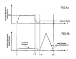
- FIGS. 4a and 4b show a state where the current supplied from the subsidiary power supply circuit is increased.
- an axis of abscissa represents time and an axis of ordinate represents a voltage between the electrodes.
- an axis of abscissa represents time and an axis of ordinate represents a current between the electrodes.
- the electric discharge is maintained not to be intermitted in the delay period from the time t2 at which the electric discharge is generated to the time t4 at which the main current from the main power supply circuit rises, so that the machining current I is flown from the main power supply circuit.
- the leakage current between the electrodes when applying the voltage from the subsidiary power supply circuit is increased from the time t1 to the time t2 especially in the case where water is used as machining fluid, so that electric corrosion of the workpiece and adhesion of material of the electrode on a surface of the workpiece are increased to deteriorate quality of a machined surface.
- the present invention provides a power supplying device for electric discharge machine capable of maintaining an electric discharge between an electrode and a workpiece not to be intermitted in delay time from generation of the electric discharge to rise of a voltage from a main power supply circuit without increasing a leakage current.
- a power supply device for an electric discharge machine of the present invention comprises: a subsidiary power supply circuit to urge generation of an electric discharge by applying a voltage between the electrode and the workpiece, said subsidiary power supply circuit including a direct current power source, an switching element and a parallel circuit composed of a current reducing resistor and a capacitor, which are connected in series; a main power supplying circuit for supplying a machining current between the electrode and the workpiece; and a controller for controlling said subsidiary power supply circuit to apply the voltage between the electrode and the workpiece and controlling said main power supply circuit to apply the machining current when the generation of the electric discharge between the electrode and the workpiece is detected.
- the electric discharge is securely maintained not to be intermitted in the delay time by a sufficient current supplied through the capacitor in the delay time even if an electric discharge current vibrates in the delay time.
- the current reducing resistor suppresses the leakage current during the application of the voltage from the subsidiary power supply circuit to prevent an electric corrosion of the workpiece and an adhesion of material of the electrode to a surface of the workpiece.
- the subsidiary power supply circuit may further include a resistor connected in series for suppressing a vibration of the voltage between the electrode and the workpiece caused by capacitance of the capacitor and inductance of power cables.
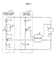
- a main power supply circuit 3 and a subsidiary power supply circuit 4 are connected with a workpiece 1 and an electrode 2 in parallel.
- the main power supply circuit comprises a series circuit composed of a main power source 31, a switching element 32 and a back flow prevention diode connected with the switching element 32 in forward direction.
- the subsidiary power supply circuit 4 comprises: a series circuit composed of a subsidiary power source 41, a switching element 42 and a resistor 43; a parallel circuit composed of a current reducing resistor 44 and a capacitor 45; and a back flow prevention diode 46, which are connected in series.
- a controller 5 for detecting a voltage between the workpiece 1 and the electrode 2 and on/off controlling the switching elements 42 and 32 is provided between the workpiece 1 and the electrode 2.
- FIGS. 2a and 2b shows an operation of the power supply device according to the embodiment of the invention.
- an axis of abscissa represents time and an axis of ordinate represents a voltage between the electrodes.
- an axis of abscissa represents time and an axis of ordinate represents a current between the electrodes.
- the controller 5 turns on the switching element 42 of the subsidiary power supply circuit 4.
- a voltage VS of the subsidiary power source 41 is applied between the workpiece 1 and the electrode through the switching element 42, the resistor 43, the parallel circuit composed of the current reducing resistor 44 and the capacitor 45, and the back flow prevention diode 46, as shown FIG. 2a.
- a leakage current between the electrodes by the application of the voltage VS from the subsidiary power source 41 is reduced to an adequately small level by the current reducing resistor 44.
- the electric corrosion of the workpiece 1 and the adhesion of material of the electrode to the surface of the workpiece are suppressed.
- the controller 5 After the application of the preliminary voltage, an electric discharge is generated and the controller 5 detects the generation of the electric discharge and turns on the switching element 32 of the main power supply circuit 3.
- the voltage VM of the main power source 31 is supplied between the electrodes through the switching element 32 and the back flow prevention diode 33 to flow a machining current I of large amount.
- the resistor 43 of an appropriate value is provided as being inserted between the parallel circuit composed of the current reducing resistor 44 and the capacitor 45, and the switching element 42, so as to prevent a phenomenon of superimposing of the vibration on the voltage between the electrodes due to capacitance of the capacitor 45 and inductance of power cables and between the electrodes when a start of application of the voltage between the electrodes.
- the resistor 43 is provided for preventing the vibration of the voltage between the electrodes.
- Both of the back flow prevention diodes 33 and 46 may not necessarily provided and only one of the diodes associated with one of the main power source 31 and the subsidiary power source 41 which has a lower voltage level than the other may be provided to prevent a back flow into the power source which has the lower voltage.
- both the back flow prevention diodes 33 and 46 are provided for the main power source 31 and the subsidiary power source 41, respectively, to cope with a case where the voltage level VM of the main power source 31 and the voltage level VS of the subsidiary power source 41 are reversed in dependence on a rough machining and a finish machining to be performed.
- an intermission of an electric discharge between the workpiece and the electrode by a preliminary voltage from a subsidiary power source in a time period from a generation of the electric discharge to a substantial rise of an machining current from a main power source is prevented to maintain the electric discharge in the delay time to realize a stable electric discharge machining without an electric corrosion of the workpiece and an adhesion of material of the electrode to a surface of the workpiece.
Landscapes
- Engineering & Computer Science (AREA)
- Mechanical Engineering (AREA)
- Electrical Discharge Machining, Electrochemical Machining, And Combined Machining (AREA)
Applications Claiming Priority (2)
| Application Number | Priority Date | Filing Date | Title |
|---|---|---|---|
| JP2002363741A JP2004195562A (ja) | 2002-12-16 | 2002-12-16 | 放電加工機の加工電源装置 |
| JP2002363741 | 2002-12-16 |
Publications (1)
| Publication Number | Publication Date |
|---|---|
| EP1430982A2 true EP1430982A2 (de) | 2004-06-23 |
Family
ID=32376206
Family Applications (1)
| Application Number | Title | Priority Date | Filing Date |
|---|---|---|---|
| EP03257895A Withdrawn EP1430982A2 (de) | 2002-12-16 | 2003-12-16 | Stromversorgung für elektrische Entladungsmaschine |
Country Status (4)
| Country | Link |
|---|---|
| US (1) | US6844517B2 (de) |
| EP (1) | EP1430982A2 (de) |
| JP (1) | JP2004195562A (de) |
| CN (1) | CN1513633A (de) |
Cited By (1)
| Publication number | Priority date | Publication date | Assignee | Title |
|---|---|---|---|---|
| CN105033371A (zh) * | 2015-08-12 | 2015-11-11 | 清华大学 | 一种电加工用防电化学杂散腐蚀的方法 |
Families Citing this family (6)
| Publication number | Priority date | Publication date | Assignee | Title |
|---|---|---|---|---|
| JP4244060B2 (ja) * | 2006-09-26 | 2009-03-25 | 村田機械株式会社 | 移動体 |
| CN101767229B (zh) * | 2008-12-30 | 2012-04-25 | 财团法人工业技术研究院 | 放电加工机节能放电电源 |
| JP5155418B2 (ja) | 2011-03-07 | 2013-03-06 | ファナック株式会社 | 放電加工装置 |
| JP5800923B2 (ja) | 2014-01-15 | 2015-10-28 | ファナック株式会社 | ワイヤ放電加工機の加工用電源装置 |
| JP6770041B2 (ja) | 2018-10-23 | 2020-10-14 | ファナック株式会社 | ワイヤ放電加工機および放電加工方法 |
| JP7851508B1 (ja) | 2025-08-20 | 2026-04-24 | 三菱電機株式会社 | 電源制御装置及び放電加工システム |
Family Cites Families (6)
| Publication number | Priority date | Publication date | Assignee | Title |
|---|---|---|---|---|
| CH613142A5 (de) * | 1977-02-23 | 1979-09-14 | Charmilles Sa Ateliers | |
| JPS58211826A (ja) * | 1982-05-28 | 1983-12-09 | Mitsubishi Electric Corp | 放電加工装置 |
| JPS59161230A (ja) | 1983-03-02 | 1984-09-12 | Mitsubishi Electric Corp | ワイヤカツト放電加工装置用加工電源 |
| JPS63312017A (ja) * | 1987-06-11 | 1988-12-20 | Mitsubishi Electric Corp | 放電加工用電源 |
| US6107593A (en) * | 1998-12-21 | 2000-08-22 | Industrial Technology Research Institute | Power apparatus for wire electric discharge machine |
| CN1184043C (zh) * | 2000-05-15 | 2005-01-12 | 三菱电机株式会社 | 放电加工用电源装置 |
-
2002
- 2002-12-16 JP JP2002363741A patent/JP2004195562A/ja active Pending
-
2003
- 2003-12-16 US US10/735,830 patent/US6844517B2/en not_active Expired - Fee Related
- 2003-12-16 EP EP03257895A patent/EP1430982A2/de not_active Withdrawn
- 2003-12-16 CN CNA2003101214175A patent/CN1513633A/zh active Pending
Cited By (1)
| Publication number | Priority date | Publication date | Assignee | Title |
|---|---|---|---|---|
| CN105033371A (zh) * | 2015-08-12 | 2015-11-11 | 清华大学 | 一种电加工用防电化学杂散腐蚀的方法 |
Also Published As
| Publication number | Publication date |
|---|---|
| JP2004195562A (ja) | 2004-07-15 |
| CN1513633A (zh) | 2004-07-21 |
| US20040124189A1 (en) | 2004-07-01 |
| US6844517B2 (en) | 2005-01-18 |
Similar Documents
| Publication | Publication Date | Title |
|---|---|---|
| US7800016B2 (en) | Polarity switching short circuiting arc welding method | |
| US10730126B2 (en) | Power supply device for wire electric discharge machining | |
| JP5264788B2 (ja) | 放電加工装置 | |
| US6660957B1 (en) | Apparatus for electric discharge machining | |
| EP1430982A2 (de) | Stromversorgung für elektrische Entladungsmaschine | |
| CN101932402A (zh) | 放电加工装置 | |
| US7148442B2 (en) | Power supply device for electric discharge machining | |
| US5416290A (en) | Electric discharge machine power supply circuit | |
| JPWO2001087526A1 (ja) | 放電加工用電源装置 | |
| WO2006046599A1 (ja) | 放電加工用電源装置及び細穴放電加工装置 | |
| US4395612A (en) | Power source circuit for electric discharge machine | |
| US9815132B2 (en) | Wire electric discharge machine | |
| US20200198037A1 (en) | Wire electrical discharge machine and control method of wire electrical discharge machine | |
| JP5466255B2 (ja) | 細穴放電加工機の放電制御方法および細穴放電加工用電源装置 | |
| JP3323457B2 (ja) | 放電加工方法及び放電加工用電源装置 | |
| JP3627084B2 (ja) | 放電加工機の電源装置 | |
| JP2002160128A (ja) | 放電加工装置 | |
| JP5372095B2 (ja) | 放電加工装置 | |
| JPS6116572B2 (de) | ||
| JP2017061023A (ja) | ワイヤ放電加工装置の加工電源装置 | |
| EP0671235B1 (de) | Stromversorgung für elektrisches entladungswerkzeug | |
| JP4875443B2 (ja) | 消耗電極アーク溶接電源の出力制御方法 | |
| JP4425056B2 (ja) | 放電加工電源装置 | |
| JPH059209B2 (de) | ||
| JP3382822B2 (ja) | アークスタート装置 |
Legal Events
| Date | Code | Title | Description |
|---|---|---|---|
| PUAI | Public reference made under article 153(3) epc to a published international application that has entered the european phase |
Free format text: ORIGINAL CODE: 0009012 |
|
| AK | Designated contracting states |
Kind code of ref document: A2 Designated state(s): AT BE BG CH CY CZ DE DK EE ES FI FR GB GR HU IE IT LI LU MC NL PT RO SE SI SK TR |
|
| AX | Request for extension of the european patent |
Extension state: AL LT LV MK |
|
| STAA | Information on the status of an ep patent application or granted ep patent |
Free format text: STATUS: THE APPLICATION HAS BEEN WITHDRAWN |
|
| 18W | Application withdrawn |
Effective date: 20051025 |