EP1430959A2 - Vorrichtung zum Mischen und Ausbringen von Mehrkomponentenmassen - Google Patents
Vorrichtung zum Mischen und Ausbringen von Mehrkomponentenmassen Download PDFInfo
- Publication number
- EP1430959A2 EP1430959A2 EP03025787A EP03025787A EP1430959A2 EP 1430959 A2 EP1430959 A2 EP 1430959A2 EP 03025787 A EP03025787 A EP 03025787A EP 03025787 A EP03025787 A EP 03025787A EP 1430959 A2 EP1430959 A2 EP 1430959A2
- Authority
- EP
- European Patent Office
- Prior art keywords
- cap
- cartridge
- squeezing
- components
- mixing
- Prior art date
- Legal status (The legal status is an assumption and is not a legal conclusion. Google has not performed a legal analysis and makes no representation as to the accuracy of the status listed.)
- Granted
Links
Images


Classifications
-
- B—PERFORMING OPERATIONS; TRANSPORTING
- B65—CONVEYING; PACKING; STORING; HANDLING THIN OR FILAMENTARY MATERIAL
- B65D—CONTAINERS FOR STORAGE OR TRANSPORT OF ARTICLES OR MATERIALS, e.g. BAGS, BARRELS, BOTTLES, BOXES, CANS, CARTONS, CRATES, DRUMS, JARS, TANKS, HOPPERS, FORWARDING CONTAINERS; ACCESSORIES, CLOSURES, OR FITTINGS THEREFOR; PACKAGING ELEMENTS; PACKAGES
- B65D81/00—Containers, packaging elements, or packages, for contents presenting particular transport or storage problems, or adapted to be used for non-packaging purposes after removal of contents
- B65D81/32—Containers, packaging elements, or packages, for contents presenting particular transport or storage problems, or adapted to be used for non-packaging purposes after removal of contents for packaging two or more different materials which must be maintained separate prior to use in admixture
- B65D81/3283—Cylindrical or polygonal containers, e.g. bottles, with two or more substantially axially offset, side-by-side compartments for simultaneous dispensing
-
- A—HUMAN NECESSITIES
- A61—MEDICAL OR VETERINARY SCIENCE; HYGIENE
- A61C—DENTISTRY; APPARATUS OR METHODS FOR ORAL OR DENTAL HYGIENE
- A61C5/00—Filling or capping teeth
- A61C5/60—Devices specially adapted for pressing or mixing capping or filling materials, e.g. amalgam presses
- A61C5/62—Applicators, e.g. syringes or guns
- A61C5/64—Applicators, e.g. syringes or guns for multi-component compositions
-
- A—HUMAN NECESSITIES
- A61—MEDICAL OR VETERINARY SCIENCE; HYGIENE
- A61C—DENTISTRY; APPARATUS OR METHODS FOR ORAL OR DENTAL HYGIENE
- A61C9/00—Impression cups, i.e. impression trays; Impression methods
- A61C9/0026—Syringes or guns for injecting impression material; Mixing impression material for immediate use
-
- B—PERFORMING OPERATIONS; TRANSPORTING
- B05—SPRAYING OR ATOMISING IN GENERAL; APPLYING FLUENT MATERIALS TO SURFACES, IN GENERAL
- B05C—APPARATUS FOR APPLYING FLUENT MATERIALS TO SURFACES, IN GENERAL
- B05C17/00—Hand tools or apparatus using hand held tools, for applying liquids or other fluent materials to, for spreading applied liquids or other fluent materials on, or for partially removing applied liquids or other fluent materials from, surfaces
- B05C17/005—Hand tools or apparatus using hand held tools, for applying liquids or other fluent materials to, for spreading applied liquids or other fluent materials on, or for partially removing applied liquids or other fluent materials from, surfaces for discharging material from a reservoir or container located in or on the hand tool through an outlet orifice by pressure without using surface contacting members like pads or brushes
- B05C17/00553—Hand tools or apparatus using hand held tools, for applying liquids or other fluent materials to, for spreading applied liquids or other fluent materials on, or for partially removing applied liquids or other fluent materials from, surfaces for discharging material from a reservoir or container located in or on the hand tool through an outlet orifice by pressure without using surface contacting members like pads or brushes with means allowing the stock of material to consist of at least two different components
-
- B—PERFORMING OPERATIONS; TRANSPORTING
- B05—SPRAYING OR ATOMISING IN GENERAL; APPLYING FLUENT MATERIALS TO SURFACES, IN GENERAL
- B05C—APPARATUS FOR APPLYING FLUENT MATERIALS TO SURFACES, IN GENERAL
- B05C17/00—Hand tools or apparatus using hand held tools, for applying liquids or other fluent materials to, for spreading applied liquids or other fluent materials on, or for partially removing applied liquids or other fluent materials from, surfaces
- B05C17/005—Hand tools or apparatus using hand held tools, for applying liquids or other fluent materials to, for spreading applied liquids or other fluent materials on, or for partially removing applied liquids or other fluent materials from, surfaces for discharging material from a reservoir or container located in or on the hand tool through an outlet orifice by pressure without using surface contacting members like pads or brushes
- B05C17/00503—Details of the outlet element
- B05C17/00506—Means for connecting the outlet element to, or for disconnecting it from, the hand tool or its container
-
- B—PERFORMING OPERATIONS; TRANSPORTING
- B05—SPRAYING OR ATOMISING IN GENERAL; APPLYING FLUENT MATERIALS TO SURFACES, IN GENERAL
- B05C—APPARATUS FOR APPLYING FLUENT MATERIALS TO SURFACES, IN GENERAL
- B05C17/00—Hand tools or apparatus using hand held tools, for applying liquids or other fluent materials to, for spreading applied liquids or other fluent materials on, or for partially removing applied liquids or other fluent materials from, surfaces
- B05C17/005—Hand tools or apparatus using hand held tools, for applying liquids or other fluent materials to, for spreading applied liquids or other fluent materials on, or for partially removing applied liquids or other fluent materials from, surfaces for discharging material from a reservoir or container located in or on the hand tool through an outlet orifice by pressure without using surface contacting members like pads or brushes
- B05C17/00503—Details of the outlet element
- B05C17/00516—Shape or geometry of the outlet orifice or the outlet element
Definitions
- the invention relates to a device for mixing and Spreading multicomponent compositions, in particular for dental purposes with a cartridge with at least two in parallel arranged cylindrical chambers for receiving the components and one piston each for pressing out the components, the chambers having outlet openings which are covered by a cap which is a mixing helix including exhaust tube, the cap of a position closing the outlet openings in a the same releasing position is movable.
- a known device of this type, but not intended for dental purposes has two cylindrical chambers, each with a component is included.
- the chambers are on their front with openings that are closed by a cap are.
- the cap has a sleeve-shaped outlet tube, which encloses a mixing spiral.
- the cap closes first the openings of the chambers. Should the two-component mass are issued, pull the cap so that this a little bit from the cartridge with the two chambers moved away and releases the outlet openings. With help of pistons in the chambers to which pressure is applied can then put the components in the cap and from there in the sleeve-shaped outlet tube can be pressed. During the The components pass through this outlet tube mixed by the mixing spiral.
- Such devices are also very useful for dental purposes. It is not necessary to have a separate cap to be provided, which must be removed and by a Cap must be replaced, the outlet tube and the Mixing spiral contains.
- a disadvantage of such devices is but in that a separate handle is required is to pull the cap to open it bring to. This is not only cumbersome; it exists there is also the danger that the cap may be accidentally removed entirely. Also in the manufacture of such previously known devices problems arise.
- the same model of cartridges is said may be delivered with different caps. Depending on the application, they are straight or curved Outlet tubes required. These caps must then be used also be provided with a mixing helix, are therefore proportional expensive parts. In addition, the attachment of the Mixing spiral in the cap is not easy.
- the object of the invention is to create a Device of the type mentioned that is light and error-free is to use and inexpensive and practical Mass production allowed.
- the solution according to the invention is that the cap by the pressure of the components when they are pressed out is movable into the open position and on the cartridge between the outlet openings extending to the cap Transverse wall is provided on which the mixing spiral is attached is.
- the cap It is no longer necessary to pull the cap. Rather, it has one facing the cartridge inner surface that is large enough that the pressure of the Components when these are squeezed out into the cap open position moved.
- the mixing spiral is at the Cartridge and not attached to the cap. It is closed this purpose attached to a transverse wall, the other.
- the cap is expedient in relation to the cartridge rotatable, because then the operator with a curved outlet tube can set this outlet tube as it is is most convenient for them.
- the rotatability is only guaranteed when the cap is in the open position is moved.
- the transverse wall is closed Cap enclosed by the cap or on both sides gripped in such a way that rotation is not possible. This makes it possible to cover the inner surface areas of the Cap that closes the outlet openings of the chambers should be optimally trained for this purpose.
- caps with outlet tubes can be used used the different curvatures exhibit.
- the device expediently has latching devices for the closed and the open position. there must the locking device for the closed position of course in their holding force to the opening force be adjusted by the pressure of the components so that the The cap is actually only opened by applying pressure can become and you don't have to pull on it.
- the latching device expediently has for the open one Position a greater holding force than the locking device for the closed position, otherwise there is a risk that the cap is completely detached from the cartridge when the operator has the force to open was not subsequently reduced.
- the locking device for the open position is a snap-in locking device that one further opening movement of the cap a greater resistance opposed to a closing movement.
- sawtooth-shaped in cross section Surfaces are provided that the cap is pushed on facilitate the cartridge due to the inclined surfaces, whereby but then a movement in the opposite direction for pulling off the cap, the surfaces perpendicular to the axis prevent the cap from loosening.
- the device is designed for more than two components can be, it is particularly useful for two Components and designed accordingly with two chambers.
- the device according to the invention is particularly suitable for single use. It can also be relatively small be formed and with a squeezing device or with Can be operated with the help of an adapter using larger pliers.
- the squeezing device or adapter can be used Surfaces are formed that hold the cap so that these do not move after opening, from the Loosen the cartridge and get into the patient's mouth can.
- This Device 19 is at the outlet end of the outlet tube 12 Device 19 for distributing or even Provided on / introduction of the multi-component mass.
- This Device 19 can be a brush, a small sponge, a Brush, nozzle, spatula and the like.
- the Device 19 can be designed as an additional attachment part be placed on the outlet tube 12.
- the Device 19 can also be made in one piece with the outlet tube 12 be formed.
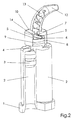
- the device of the invention shown in Figs. 1 and 2 is a cartridge 1, the two cylindrical Contains chambers 2, in each of which a component (not shown) and a piston 3 are arranged (FIG. 2), by means of a suitable one from below in the figures Tool upward pressure can be applied to the components to push up through channels 4 and openings 5. These openings are on a circular surface 6 provided, which is divided by a transverse wall 7.
- the Surface 6 is on a circular cylindrical Projection of the cartridge, which has an annular bead 9 having.
- On this cylindrical projection 8 is one Cap 10 put on, the annular on its inner wall Has recesses 11 which with the annular bead 9th can work together.
- the cap 10 has a curved Outlet tube 12, which surrounds a mixing coil 13, the is attached to the transverse wall 7.
- the annular bead 9 engages into the upper annular recess 11 of the cap 10.
- the substantially circular inner surface of the cap 10 covers the openings 5 so that the chambers 2 are closed are.
- the transverse wall 7 is in a recess 20th held against rotation, which can be seen in Fig. 2 is. Is pressure on the piston 3 and thus the components exercised, the cap 10 of the 1 in the position shown in Fig. 2 Position moved.
- the cylindrical inner surface of the cap 10 moves away from the outlet openings 5, so that the Components can leak.
- the components are included separated from each other by the transverse wall 7, so that the respective a component does not easily enter chamber 2 the other component can reach.
- the cross wall 7 is no longer held by the recess 20, so that the cap 10 can be rotated and the operator the outlet tube 12 can rotate in the direction for it is particularly useful.
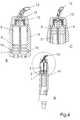
- Fig. 3 shows detailed representations of how the cap 10 with the help of the annular bead 9 and the recesses 11 becomes. Above at A it is shown that the ring-shaped Bead located in the upper recess 11, the cap 10 thus occupies its lower position and the openings 5 closes. In the representation B, the cap has changed moves up and is at its lower recess 11 from Bead 9 held in this open position.
- FIG. 4 differs from that 3 in that the bead 9 of the cylindrical Projection 8 of the cartridge has a lower straight surface has, the lower recess 11 of the cap 10 also has a corresponding straight surface. By working together these straight surfaces are prevented from the cap 10 is open from that shown at B in FIG Position can move further up. This will a detachment of the cap 10 e.g. in the patient's mouth prevented.
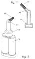
- FIG. 5 an adapter 14 is shown which has an upper opening has, in which the cartridge 1 with the cap 10 and the outlet tube 12 can be used.
- This adapter 14 can in turn be placed on pliers 18 which intended for other, especially larger cartridges and is commercially available.
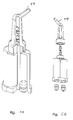
- Fig. 6 shows in section the adapter 14 with the inserted Cartridge 1.
- An overall view is shown at A, at B and C are detailed views.
- a further stop surface 17 prevents the cap 10 from further upward movement when closed by the Position (at B in Fig. 6) in the open Position (at C in Fig. 6) is moved. Through this stop surface 17 is thus reliably prevented that the cap 10 can jump off.
- the adapter has the advantage that the device according to the invention also with other commercially available Pliers can be used. Of course should not be ruled out that special Pliers created for the devices according to the invention can be, which then also under the protection area covered by this patent.
- Figure 7 is a cross section through another embodiment the outlet tube 12 shown at the end of the outlet the same means 19 for distributing or spreading the squeezed multicomponent mass is arranged.
- the device 19 for distributing or spreading can be a Brush (Fig. 7, 8, 9, 10, 17, 18), a sponge (Fig. 11), a brush (Fig. 12), a nozzle (Fig. 13, 19, 20), a spatula (Fig. 14) or the like.
- the device 19 for distribution the finished multi-component mass onto the outlet tube 12 placed so that here different parts 19 optionally can be attached to the outlet tube 12. This is also in the embodiment of FIGS. 15 and 16 the case.
Landscapes
- Health & Medical Sciences (AREA)
- General Health & Medical Sciences (AREA)
- Veterinary Medicine (AREA)
- Epidemiology (AREA)
- Life Sciences & Earth Sciences (AREA)
- Animal Behavior & Ethology (AREA)
- Oral & Maxillofacial Surgery (AREA)
- Public Health (AREA)
- Dentistry (AREA)
- Engineering & Computer Science (AREA)
- Mechanical Engineering (AREA)
- Dental Tools And Instruments Or Auxiliary Dental Instruments (AREA)
- Coating Apparatus (AREA)
- Processing And Handling Of Plastics And Other Materials For Molding In General (AREA)
- Nozzles (AREA)
Abstract
Description
- Fig. 1
- die Vorrichtung im geschlossenen Zustand;
- Fig. 2
- die Vorrichtung, teilweise aufgeschnitten, im geöffneten Zustand;
- Fig. 3
- Detailansichten im Schnitt der Ausführungsform der Fig. 1 und 2;
- Fig. 4
- Detailansichten einer etwas anderen Ausführungsform;
- Fig. 5
- die Verwendung der erfindungsgemäßen Vorrichtung in einer Auspreßzange mit einem Adapter;
- Fig. 6
- Einzelheiten im Schnitt des Adapters der Fig. 5 mit eingesetzter erfindungsgemäßer Vorrichtung;
- Fig. 7
- Im Schnitt eine Auslaßröhre mit einer Einrichtung zum Verteilen der fertigen Mehrkomponentenmasse;
- Fig. 8
- In perspektivischer Ansicht eine andere Ausführungsform mit einer Einrichtung zum Verteilen der fertigen Mehrkomponentenmasse; und
- Fig. 9-20
- weitere Ansichten und Ausführungsformen.
Claims (13)
- Vorrichtung zum Mischen und Ausbringen von Mehrkomponentenmassen, insbesondere für Dentalzwecke mit einer Kartusche (1) mit mindestens zwei parallel angeordneten zylindrischen Kammern (2) zum Aufnehmen der Komponenten und jeweils einem Kolben (3) zum Auspressen der Komponenten, wobei die Kammern (2) Auslaßöffnungen (5) aufweisen, die durch eine Kappe (10) bedeckt sind, die eine eine Mischwendel (13) einschließende Auslaßröhre (12) aufweist, wobei die Kappe (10) von einer die Auslaßöffnungen (5) verschließenden Stellung in eine dieselben freigebende Stellung bewegbar ist, dadurch gekennzeichnet, daß die Kappe (10) durch den Druck der Komponenten beim Auspressen derselben in die geöffnete Stellung bewegbar ist und an der Kartusche (1) zwischen den Auslaßöffnungen (5) eine sich zur Kappe (10) erstreckende Querwand (7) vorgesehen ist, an der die Mischwendel (13) angebracht ist.
- Vorrichtung nach Anspruch 1, dadurch gekennzeichnet, daß die Kappe (10) in Bezug auf die Kartusche (1) drehbar ist und im geschlossenen Zustand die Querwand (7) so einschließt, daß diese Drehbewegung verhindert wird.
- Vorrichtung nach Anspruch 1 oder 2, dadurch gekennzeichnet, daß die Mischwendel (13) flexibel ist.
- Vorrichtung nach einem der Ansprüche 1 bis 3, dadurch gekennzeichnet, daß sie Rasteinrichtungen (9, 11) für die geschlossene und die geöffnete Stellung aufweist.
- Vorrichtung nach Anspruch 4, dadurch gekennzeichnet, daß die Rasteinrichtung (9, 11) für die offene Stellung eine größere Haltekraft hat als die Rasteinrichtung (9, 11) für die geschlossene Stellung.
- Vorrichtung nach Anspruch 4 oder 5, dadurch gekennzeichnet, daß die Rasteinrichtung (9, 11) für die offene Stellung eine Schnapp-Rast-Einrichtung ist, die einer weiteren Öffnungsbewegung der Kappe (10) eine größere Widerstandskraft entgegensetzt als einer Schließbewegung.
- Vorrichtung nach einem der Ansprüche 1 bis 6, dadurch gekennzeichnet, daß sie zwei Kammern (2) aufweist.
- Auspreßvorrichtung für die Verwendung der Vorrichtung nach einem der Ansprüche 1 bis 7, dadurch gekennzeichnet, daß sie Anschlagflächen (16, 17) aufweist, die eine Bewegung in Auspreßrichtung begrenzen, und zwar eine erste Anschlagfläche (16) für die Kartusche (1) und eine zweite Anschlagfläche (17) für die Kappe (10) im geöffneten Zustand.
- Auspreßvorrichtung nach Anspruch 8, dadurch gekennzeichnet, daß sie einen Adapter (14) für die Verwendung mit Zangen (18) für andere Kartuschen aufweist.
- Auspreßvorrichtung nach einem der Ansprüche 1 bis 9, dadurch gekennzeichnet, daß sie eine Einrichtung (19) zum Verteilen der ausgepreßten Mehrkomponentenmasse aufweist.
- Auspreßvorrichtung nach Anspruch 10, dadurch gekennzeichnet, daß die Einrichtung (19) zum Verteilen der ausgepreßten Mehrkomponentenmasse einstückig mit der Auslaßröhre (12) ausgebildet ist.
- Auspreßvorrichtung nach Anspruch 10, dadurch gekennzeichnet, daß die Einrichtung (19) zum Verteilen der fertigen Mehrkomponentenmasse lösbar auf die Auslaßröhre (12) aufgesetzt ist.
- Auspreßvorrichtung nach einem der Ansprüche 10 bis 12, dadurch gekennzeichnet, daß die Einrichtung (19) zur Verteilung der fertigen Mehrkomponentenmasse ein Pinsel, ein Schwämmchen, eine Bürste, eine Düse oder ein Spatel ist.
Applications Claiming Priority (2)
| Application Number | Priority Date | Filing Date | Title |
|---|---|---|---|
| DE10254409A DE10254409A1 (de) | 2002-11-21 | 2002-11-21 | Vorrichtung zum Mischen und Ausbringen von Mehrkomponentenmassen |
| DE10254409 | 2002-11-21 |
Publications (3)
| Publication Number | Publication Date |
|---|---|
| EP1430959A2 true EP1430959A2 (de) | 2004-06-23 |
| EP1430959A3 EP1430959A3 (de) | 2005-10-19 |
| EP1430959B1 EP1430959B1 (de) | 2008-05-07 |
Family
ID=32240259
Family Applications (1)
| Application Number | Title | Priority Date | Filing Date |
|---|---|---|---|
| EP03025787A Expired - Lifetime EP1430959B1 (de) | 2002-11-21 | 2003-11-11 | Vorrichtung zum Mischen und Ausbringen von Mehrkomponentenmassen |
Country Status (7)
| Country | Link |
|---|---|
| US (2) | US7367475B2 (de) |
| EP (1) | EP1430959B1 (de) |
| CN (1) | CN100379392C (de) |
| AT (1) | ATE394173T1 (de) |
| AU (1) | AU2003262309B8 (de) |
| CA (1) | CA2450279C (de) |
| DE (2) | DE10254409A1 (de) |
Cited By (11)
| Publication number | Priority date | Publication date | Assignee | Title |
|---|---|---|---|---|
| WO2005016783A1 (en) * | 2003-08-14 | 2005-02-24 | 3M Espe Ag | Capsule for two-component materials |
| EP1741405A1 (de) * | 2005-07-01 | 2007-01-10 | 3M Innovative Properties Company | System zur Zuführung von dentalen Werkstoffen |
| EP1825927A2 (de) | 2003-08-14 | 2007-08-29 | 3M Espe AG | Injektionsspritze für Mehrkomponentenwerkstoffe |
| DE102006047811A1 (de) * | 2006-10-06 | 2008-05-15 | Sulzer Chemtech Ag | Mehrkomponentenkartusche |
| EP1987885A1 (de) * | 2007-05-04 | 2008-11-05 | Dentaco Dentalindustrie- und Marketing GmbH | Sprühdose |
| WO2009036962A2 (en) * | 2007-09-19 | 2009-03-26 | Kettenbach Gmbh & Co. Kg | Dispensing device |
| DE102007044983A1 (de) | 2007-09-19 | 2009-04-09 | Kettenbach Gmbh & Co. Kg | Austragvorrichtung |
| WO2009053851A2 (en) * | 2007-08-30 | 2009-04-30 | Ivoclar Vivadent Ag | Pen-like dispenser |
| WO2010108868A1 (de) * | 2009-03-23 | 2010-09-30 | Sulzer Mixpac Ag | Spritze zur einmaligen verwendung |
| US8328553B2 (en) | 2006-03-09 | 2012-12-11 | 3M Innovative Properties Company | Device for dispensing material |
| EP2596873A3 (de) * | 2011-11-25 | 2013-12-11 | Heraeus Medical GmbH | Mehrkomponenten-Kartuschensystem mit verschiebbaren Verschlüssen in den Kartuschen |
Families Citing this family (33)
| Publication number | Priority date | Publication date | Assignee | Title |
|---|---|---|---|---|
| DE10112904C5 (de) * | 2001-03-15 | 2010-04-22 | 3M Espe Ag | Dynamischer Mischer und Verfahren zum Mischen von mindestens zwei Pastenkomponenten |
| ATE297249T1 (de) * | 2003-08-14 | 2005-06-15 | 3M Espe Ag | Mischelement für einen mehrkomponentenpastenmischer, und mischer mit diesem mischelement |
| EP1588779A1 (de) * | 2004-04-19 | 2005-10-26 | 3M Espe AG | Dynamischer Mischer |
| EP1640060A1 (de) | 2004-09-22 | 2006-03-29 | 3M Espe Ag | Mischer für Mehrkomponentenpasten, Bausatz, und Verfahren zum Mischen von Pasten |
| US8322909B2 (en) * | 2004-09-22 | 2012-12-04 | 3M Deutschland Gmbh | Mixer for multi-component pastes, kit, and method of mixing paste components |
| US20120017412A1 (en) * | 2004-12-03 | 2012-01-26 | Paul Richard Pierson | Package and dispensing system |
| DE102005041961B4 (de) * | 2005-09-03 | 2007-08-02 | Kettenbach Gmbh & Co. Kg | Kartusche |
| US8197545B2 (en) | 2005-10-27 | 2012-06-12 | Depuy Spine, Inc. | Nucleus augmentation delivery device and technique |
| BRPI0621269A2 (pt) * | 2005-12-29 | 2011-12-06 | Sulzer Mixpac Ag | dispositivo de distribuição para uso único |
| US10631558B2 (en) | 2006-03-06 | 2020-04-28 | The Coca-Cola Company | Methods and apparatuses for making compositions comprising an acid and an acid degradable component and/or compositions comprising a plurality of selectable components |
| US8162176B2 (en) | 2007-09-06 | 2012-04-24 | The Coca-Cola Company | Method and apparatuses for providing a selectable beverage |
| EP2190592B2 (de) † | 2007-09-19 | 2015-08-26 | Kettenbach GmbH & CO. KG | Behälter |
| DE202008007801U1 (de) | 2007-09-19 | 2008-08-21 | Kettenbach Gmbh & Co. Kg | Behälter |
| GB0902354D0 (en) | 2009-02-13 | 2009-04-01 | 3M Innovative Properties Co | Syringes for dispensing multicomponent material |
| US9867788B2 (en) * | 2009-07-09 | 2018-01-16 | Boston Scientific Scimed, Inc. | Multi-chamber cellular mixing and delivery system and method |
| USD657876S1 (en) | 2010-02-02 | 2012-04-17 | 3M Innovative Properties Company | Dental capsule |
| EP2382941A1 (de) * | 2010-04-29 | 2011-11-02 | 3M Innovative Properties Company | System mit einer Misch- und Ausgabevorrichtung und Materialbehälter |
| DE102010019222B4 (de) | 2010-05-04 | 2013-11-07 | Heraeus Medical Gmbh | Austragsvorrichtung für Kartuschen |
| DE102010019223B4 (de) | 2010-05-04 | 2012-02-16 | Heraeus Medical Gmbh | Kartuschensystem mit Druckgaspatrone |
| DE102010019219B4 (de) | 2010-05-04 | 2013-12-12 | Heraeus Medical Gmbh | Kartuschenverschluss und Kartusche mit einem solchen Verschluss |
| DE102010019217B4 (de) | 2010-05-04 | 2014-01-16 | Heraeus Medical Gmbh | Kartuschensystem |
| DE102010019224B3 (de) | 2010-05-04 | 2011-10-13 | Heraeus Medical Gmbh | Austragsvorrichtung für pastöse Massen |
| EP2495003B1 (de) | 2011-03-04 | 2014-11-19 | 3M Innovative Properties Co. | Kolben für eine Spritze und Verfahren zur Herstellung eines solchen Kolbens |
| ES2437941T3 (es) | 2011-03-11 | 2014-01-15 | Sulzer Mixpac Ag | Cartucho de múltiples componentes |
| USD679810S1 (en) | 2011-03-28 | 2013-04-09 | 3M Innovative Properties Company | Dental syringe |
| WO2014063848A1 (de) * | 2012-10-23 | 2014-05-01 | Sulzer Mixpac Ag | Austragvorrichtung |
| US9138772B2 (en) | 2012-10-31 | 2015-09-22 | Nordson Corporation | Dispensing assembly and method using snap engagement of a mixer and a cartridge |
| KR102023143B1 (ko) * | 2012-11-08 | 2019-09-19 | 술저 믹스팩 아게 | 2개 이상의 유동성 성분을 위한 카트리지 |
| USD732163S1 (en) * | 2013-07-24 | 2015-06-16 | Blephex, Llc | Instrument for treating an ocular disorder |
| EP2959861A1 (de) | 2014-06-23 | 2015-12-30 | Sulzer Mixpac AG | Spritzen zur abgabe eines aus mehreren komponenten bestehenden materials |
| CA3006547A1 (en) * | 2015-12-17 | 2017-06-22 | Colgate-Palmolive Company | Hydrogen peroxide booster system for enhanced teeth whitening |
| CN105564829B (zh) * | 2016-02-24 | 2017-11-17 | 深圳市德昌裕塑胶制品有限公司 | 单口出液双软管容器及混合器 |
| CN111671531B (zh) * | 2020-06-12 | 2021-07-16 | 杭州牙科医院有限公司 | 一种根管治疗用根管糊剂填充器 |
Citations (5)
| Publication number | Priority date | Publication date | Assignee | Title |
|---|---|---|---|---|
| FR806639A (fr) * | 1936-02-14 | 1936-12-21 | Betts & Company | Perfectionnements aux tubes déformables par écrasement |
| DE3420324A1 (de) * | 1984-05-30 | 1985-12-05 | Lechler Chemie Gmbh, 7000 Stuttgart | Abgabevorrichtung fuer mehrere stroemungsfaehige materialkomponenten |
| EP0319135A2 (de) * | 1987-10-22 | 1989-06-07 | Illinois Tool Works Inc. | Einrichtung zur Abgabe eines Gemisches mehrerer Komponenten |
| DE29518531U1 (de) * | 1995-11-22 | 1996-02-01 | Eugen Prestele Kunststoffprodu | Kartusche |
| US6477743B1 (en) * | 2001-08-14 | 2002-11-12 | Seaquist Closures Foreign, Inc. | Twist-openable dispensing closure accommodating optional liner puncture feature |
Family Cites Families (14)
| Publication number | Priority date | Publication date | Assignee | Title |
|---|---|---|---|---|
| US3200995A (en) * | 1962-08-30 | 1965-08-17 | Colgate Palmolive Co | Multicompartment dispensing package |
| US3876118A (en) * | 1973-08-10 | 1975-04-08 | Adolfo Arias Loredo | Dispensing container closure |
| US3900954A (en) * | 1974-07-10 | 1975-08-26 | William B Dragan | Dental filling gun and nozzle tip therefor |
| US4846373A (en) * | 1982-09-07 | 1989-07-11 | Penn Laurence R | Apparatus for proportioning or for proportioning and mixing plural different fluid compositions |
| FR2652567B1 (fr) * | 1989-10-04 | 1992-01-10 | Oreal | Dispositif de distribution comportant au moins un flacon a embout cassable. |
| CH681146A5 (de) * | 1990-07-20 | 1993-01-29 | Wilhelm A Keller | |
| US5269684A (en) * | 1992-08-31 | 1993-12-14 | Ultradent Products, Inc. | Adjustable brush delivery tip with secondary flow path |
| US5333760A (en) * | 1992-12-28 | 1994-08-02 | Coltene/Whaledent, Inc. | Dispensing and mixing apparatus |
| US5443183A (en) * | 1993-11-18 | 1995-08-22 | Jacobsen; Kenneth H. | Unitary check valve |
| US5413253A (en) * | 1993-12-06 | 1995-05-09 | Coltene/Whaledent, Inc. | Static mixer |
| DE69716887T2 (de) * | 1997-06-18 | 2003-03-20 | Wilhelm A Keller | Mischer |
| AU5678699A (en) * | 1998-08-27 | 2000-03-21 | Bowles Fluidics Corporation | Water bottle with drinking and spray modes |
| US6352177B1 (en) * | 1998-10-14 | 2002-03-05 | Kettenbach Gmbh & Co. Kg | Device for discharging a pasty two-component mixture |
| US6398077B1 (en) * | 2000-02-11 | 2002-06-04 | Seaquist Closures Foreign, Inc. | Package with multiple chambers and valves |
-
2002
- 2002-11-21 DE DE10254409A patent/DE10254409A1/de not_active Withdrawn
-
2003
- 2003-11-11 AT AT03025787T patent/ATE394173T1/de not_active IP Right Cessation
- 2003-11-11 DE DE50309770T patent/DE50309770D1/de not_active Expired - Lifetime
- 2003-11-11 EP EP03025787A patent/EP1430959B1/de not_active Expired - Lifetime
- 2003-11-17 AU AU2003262309A patent/AU2003262309B8/en not_active Ceased
- 2003-11-19 CA CA2450279A patent/CA2450279C/en not_active Expired - Fee Related
- 2003-11-20 US US10/718,393 patent/US7367475B2/en active Active
- 2003-11-21 CN CNB2003101233212A patent/CN100379392C/zh not_active Expired - Fee Related
-
2006
- 2006-10-05 US US11/543,497 patent/US7383969B2/en not_active Expired - Lifetime
Patent Citations (5)
| Publication number | Priority date | Publication date | Assignee | Title |
|---|---|---|---|---|
| FR806639A (fr) * | 1936-02-14 | 1936-12-21 | Betts & Company | Perfectionnements aux tubes déformables par écrasement |
| DE3420324A1 (de) * | 1984-05-30 | 1985-12-05 | Lechler Chemie Gmbh, 7000 Stuttgart | Abgabevorrichtung fuer mehrere stroemungsfaehige materialkomponenten |
| EP0319135A2 (de) * | 1987-10-22 | 1989-06-07 | Illinois Tool Works Inc. | Einrichtung zur Abgabe eines Gemisches mehrerer Komponenten |
| DE29518531U1 (de) * | 1995-11-22 | 1996-02-01 | Eugen Prestele Kunststoffprodu | Kartusche |
| US6477743B1 (en) * | 2001-08-14 | 2002-11-12 | Seaquist Closures Foreign, Inc. | Twist-openable dispensing closure accommodating optional liner puncture feature |
Cited By (24)
| Publication number | Priority date | Publication date | Assignee | Title |
|---|---|---|---|---|
| WO2005016783A1 (en) * | 2003-08-14 | 2005-02-24 | 3M Espe Ag | Capsule for two-component materials |
| EP1825927A2 (de) | 2003-08-14 | 2007-08-29 | 3M Espe AG | Injektionsspritze für Mehrkomponentenwerkstoffe |
| EP1825927A3 (de) * | 2003-08-14 | 2008-02-27 | 3M Espe AG | Injektionsspritze für Mehrkomponentenwerkstoffe |
| US8561845B2 (en) | 2003-08-14 | 2013-10-22 | 3M Innovative Properties Company | Capsule for two-component materials |
| US7882983B2 (en) | 2003-08-14 | 2011-02-08 | 3M Innovative Properties Company | Capsule for two-component materials |
| EP1741405A1 (de) * | 2005-07-01 | 2007-01-10 | 3M Innovative Properties Company | System zur Zuführung von dentalen Werkstoffen |
| US9211168B2 (en) | 2006-03-09 | 2015-12-15 | 3M Innovative Properties Company | Device for dispensing material |
| US8328553B2 (en) | 2006-03-09 | 2012-12-11 | 3M Innovative Properties Company | Device for dispensing material |
| DE102006047811A1 (de) * | 2006-10-06 | 2008-05-15 | Sulzer Chemtech Ag | Mehrkomponentenkartusche |
| US7997450B2 (en) | 2006-10-06 | 2011-08-16 | Sulzer Mixpac Ag | Multicomponent cartridge |
| EP1987885A1 (de) * | 2007-05-04 | 2008-11-05 | Dentaco Dentalindustrie- und Marketing GmbH | Sprühdose |
| WO2009053851A2 (en) * | 2007-08-30 | 2009-04-30 | Ivoclar Vivadent Ag | Pen-like dispenser |
| WO2009053851A3 (en) * | 2007-08-30 | 2009-12-03 | Ivoclar Vivadent Ag | Pen-like dispenser |
| WO2009036962A2 (en) * | 2007-09-19 | 2009-03-26 | Kettenbach Gmbh & Co. Kg | Dispensing device |
| WO2009036962A3 (en) * | 2007-09-19 | 2009-07-09 | Kettenbach Gmbh & Co Kg | Dispensing device |
| DE102007044983B4 (de) * | 2007-09-19 | 2014-03-20 | Kettenbach Gmbh & Co. Kg | Austragvorrichtung |
| US9168108B2 (en) | 2007-09-19 | 2015-10-27 | Kettenbach Gmbh & Co. Kg | Dispensing device |
| DE102007044983A1 (de) | 2007-09-19 | 2009-04-09 | Kettenbach Gmbh & Co. Kg | Austragvorrichtung |
| KR20120001772A (ko) * | 2009-03-23 | 2012-01-04 | 술저 믹스팩 아게 | 일회용 주사기 |
| WO2010108868A1 (de) * | 2009-03-23 | 2010-09-30 | Sulzer Mixpac Ag | Spritze zur einmaligen verwendung |
| US8978929B2 (en) | 2009-03-23 | 2015-03-17 | Sulzer Mixpac Ag | Syringe for single use |
| KR101698938B1 (ko) | 2009-03-23 | 2017-01-23 | 술저 믹스팩 아게 | 일회용 주사기 |
| EP2596873A3 (de) * | 2011-11-25 | 2013-12-11 | Heraeus Medical GmbH | Mehrkomponenten-Kartuschensystem mit verschiebbaren Verschlüssen in den Kartuschen |
| US8986313B2 (en) | 2011-11-25 | 2015-03-24 | Heraeus Medical Gmbh | Multi-component cartridge system with shiftable closures in the cartridges |
Also Published As
| Publication number | Publication date |
|---|---|
| US7383969B2 (en) | 2008-06-10 |
| CA2450279C (en) | 2013-02-05 |
| ATE394173T1 (de) | 2008-05-15 |
| CN1509693A (zh) | 2004-07-07 |
| EP1430959A3 (de) | 2005-10-19 |
| CA2450279A1 (en) | 2004-05-21 |
| DE10254409A1 (de) | 2004-06-03 |
| AU2003262309B8 (en) | 2008-09-11 |
| CN100379392C (zh) | 2008-04-09 |
| US7367475B2 (en) | 2008-05-06 |
| AU2003262309A1 (en) | 2004-06-10 |
| US20040104249A1 (en) | 2004-06-03 |
| AU2003262309B2 (en) | 2008-07-03 |
| US20070023450A1 (en) | 2007-02-01 |
| DE50309770D1 (de) | 2008-06-19 |
| EP1430959B1 (de) | 2008-05-07 |
Similar Documents
| Publication | Publication Date | Title |
|---|---|---|
| EP1430959B1 (de) | Vorrichtung zum Mischen und Ausbringen von Mehrkomponentenmassen | |
| EP1121195B1 (de) | Vorrichtung zum austragen eines pastösen zweikomponenten-gemisches | |
| EP2384871B1 (de) | Austragsvorrichtung für Kartuschen | |
| EP0645124B1 (de) | Spritze zum dosierten Abgeben von viskosen Werkstoffen, insbesondere von dentalen Werkstoffen | |
| EP0254969A1 (de) | Vorrichtung zum strangförmigen Austragen von pastösen Massen | |
| EP2384724B1 (de) | Austragsvorrichtung für pastöse Massen | |
| DE3407648A1 (de) | Behaelter zum ausbringen von dentalmassen | |
| DE2537022A1 (de) | Geraet zum messen, mischen und ausgeben von zwei komponenten aufweisenden materialien | |
| EP0910995A2 (de) | Dentales Handgerät zum Mischen und Ausbringen einer Mehrkomponenten-Formmasse | |
| DE10233051A1 (de) | Abgabesystem für fluide Substanzen | |
| CH683515A5 (de) | Vorrichtung zum Ausbringen einer aus mindestens zwei Komponenten bestehenden Mischung. | |
| EP0909590B1 (de) | Handgerät zum Ausbringen einer viskosen Flüssigkeit | |
| DE10038882A1 (de) | Vorrichtung zum Ausgeben einer gemischten Mehrkomponentenmasse, insbesondere für zahnärztliche Zwecke | |
| DE19725863A1 (de) | Betätigungseinrichtung | |
| EP3045143B1 (de) | Mischkapsel zur herstellung eines dentalpräparats | |
| AT410397B (de) | Misch- und applikationskapsel für ein dentalpräparat | |
| DE3316338A1 (de) | Einsetzwerkzeug | |
| WO1995020891A1 (de) | Applikations-system | |
| EP1575445A1 (de) | Vorrichtung zum ausgeben einer gemischten mehrkomponentenmasse | |
| DE19906887C1 (de) | Misch- und Applikationskapsel | |
| WO2005080006A2 (de) | Vorrichtung zum formen von fugen | |
| DE19681702B4 (de) | Zweikomponenten-Aerosol-Dose | |
| DE7908402U1 (de) | Einhandbetaetigbare abgabevorrichtung fuer pastenartige substanzen | |
| DE102005045359B4 (de) | Applikationsgerät für Dentalmassen | |
| EP0122514B1 (de) | Vorrichtung zur Abgabe wenigstens eines Konzentrats für wenigstens eine Zugabe zu einem Lösungsmittel, auch mit Betätigungseinrichtung |
Legal Events
| Date | Code | Title | Description |
|---|---|---|---|
| PUAI | Public reference made under article 153(3) epc to a published international application that has entered the european phase |
Free format text: ORIGINAL CODE: 0009012 |
|
| AK | Designated contracting states |
Kind code of ref document: A2 Designated state(s): AT BE BG CH CY CZ DE DK EE ES FI FR GB GR HU IE IT LI LU MC NL PT RO SE SI SK TR |
|
| AX | Request for extension of the european patent |
Extension state: AL LT LV MK |
|
| PUAL | Search report despatched |
Free format text: ORIGINAL CODE: 0009013 |
|
| AK | Designated contracting states |
Kind code of ref document: A3 Designated state(s): AT BE BG CH CY CZ DE DK EE ES FI FR GB GR HU IE IT LI LU MC NL PT RO SE SI SK TR |
|
| AX | Request for extension of the european patent |
Extension state: AL LT LV MK |
|
| 17P | Request for examination filed |
Effective date: 20060406 |
|
| AKX | Designation fees paid |
Designated state(s): AT BE BG CH CY CZ DE DK EE ES FI FR GB GR HU IE IT LI LU MC NL PT RO SE SI SK TR |
|
| GRAP | Despatch of communication of intention to grant a patent |
Free format text: ORIGINAL CODE: EPIDOSNIGR1 |
|
| GRAS | Grant fee paid |
Free format text: ORIGINAL CODE: EPIDOSNIGR3 |
|
| GRAA | (expected) grant |
Free format text: ORIGINAL CODE: 0009210 |
|
| AK | Designated contracting states |
Kind code of ref document: B1 Designated state(s): AT BE BG CH CY CZ DE DK EE ES FI FR GB GR HU IE IT LI LU MC NL PT RO SE SI SK TR |
|
| REG | Reference to a national code |
Ref country code: GB Ref legal event code: FG4D Free format text: NOT ENGLISH |
|
| REG | Reference to a national code |
Ref country code: CH Ref legal event code: EP |
|
| REG | Reference to a national code |
Ref country code: IE Ref legal event code: FG4D Free format text: LANGUAGE OF EP DOCUMENT: GERMAN |
|
| REF | Corresponds to: |
Ref document number: 50309770 Country of ref document: DE Date of ref document: 20080619 Kind code of ref document: P |
|
| REG | Reference to a national code |
Ref country code: CH Ref legal event code: NV Representative=s name: DR. R.C. SALGO + PARTNER PATENTANWAELTE AG |
|
| PG25 | Lapsed in a contracting state [announced via postgrant information from national office to epo] |
Ref country code: SI Free format text: LAPSE BECAUSE OF FAILURE TO SUBMIT A TRANSLATION OF THE DESCRIPTION OR TO PAY THE FEE WITHIN THE PRESCRIBED TIME-LIMIT Effective date: 20080507 |
|
| PG25 | Lapsed in a contracting state [announced via postgrant information from national office to epo] |
Ref country code: NL Free format text: LAPSE BECAUSE OF FAILURE TO SUBMIT A TRANSLATION OF THE DESCRIPTION OR TO PAY THE FEE WITHIN THE PRESCRIBED TIME-LIMIT Effective date: 20080507 Ref country code: ES Free format text: LAPSE BECAUSE OF FAILURE TO SUBMIT A TRANSLATION OF THE DESCRIPTION OR TO PAY THE FEE WITHIN THE PRESCRIBED TIME-LIMIT Effective date: 20080818 Ref country code: FI Free format text: LAPSE BECAUSE OF FAILURE TO SUBMIT A TRANSLATION OF THE DESCRIPTION OR TO PAY THE FEE WITHIN THE PRESCRIBED TIME-LIMIT Effective date: 20080507 |
|
| NLV1 | Nl: lapsed or annulled due to failure to fulfill the requirements of art. 29p and 29m of the patents act | ||
| REG | Reference to a national code |
Ref country code: IE Ref legal event code: FD4D |
|
| PG25 | Lapsed in a contracting state [announced via postgrant information from national office to epo] |
Ref country code: CZ Free format text: LAPSE BECAUSE OF FAILURE TO SUBMIT A TRANSLATION OF THE DESCRIPTION OR TO PAY THE FEE WITHIN THE PRESCRIBED TIME-LIMIT Effective date: 20080507 Ref country code: IE Free format text: LAPSE BECAUSE OF FAILURE TO SUBMIT A TRANSLATION OF THE DESCRIPTION OR TO PAY THE FEE WITHIN THE PRESCRIBED TIME-LIMIT Effective date: 20080507 Ref country code: DK Free format text: LAPSE BECAUSE OF FAILURE TO SUBMIT A TRANSLATION OF THE DESCRIPTION OR TO PAY THE FEE WITHIN THE PRESCRIBED TIME-LIMIT Effective date: 20080507 Ref country code: SE Free format text: LAPSE BECAUSE OF FAILURE TO SUBMIT A TRANSLATION OF THE DESCRIPTION OR TO PAY THE FEE WITHIN THE PRESCRIBED TIME-LIMIT Effective date: 20080807 Ref country code: PT Free format text: LAPSE BECAUSE OF FAILURE TO SUBMIT A TRANSLATION OF THE DESCRIPTION OR TO PAY THE FEE WITHIN THE PRESCRIBED TIME-LIMIT Effective date: 20081007 |
|
| PG25 | Lapsed in a contracting state [announced via postgrant information from national office to epo] |
Ref country code: SK Free format text: LAPSE BECAUSE OF FAILURE TO SUBMIT A TRANSLATION OF THE DESCRIPTION OR TO PAY THE FEE WITHIN THE PRESCRIBED TIME-LIMIT Effective date: 20080507 Ref country code: RO Free format text: LAPSE BECAUSE OF FAILURE TO SUBMIT A TRANSLATION OF THE DESCRIPTION OR TO PAY THE FEE WITHIN THE PRESCRIBED TIME-LIMIT Effective date: 20080507 |
|
| PLBE | No opposition filed within time limit |
Free format text: ORIGINAL CODE: 0009261 |
|
| STAA | Information on the status of an ep patent application or granted ep patent |
Free format text: STATUS: NO OPPOSITION FILED WITHIN TIME LIMIT |
|
| 26N | No opposition filed |
Effective date: 20090210 |
|
| PG25 | Lapsed in a contracting state [announced via postgrant information from national office to epo] |
Ref country code: EE Free format text: LAPSE BECAUSE OF FAILURE TO SUBMIT A TRANSLATION OF THE DESCRIPTION OR TO PAY THE FEE WITHIN THE PRESCRIBED TIME-LIMIT Effective date: 20080507 Ref country code: BG Free format text: LAPSE BECAUSE OF FAILURE TO SUBMIT A TRANSLATION OF THE DESCRIPTION OR TO PAY THE FEE WITHIN THE PRESCRIBED TIME-LIMIT Effective date: 20080807 |
|
| BERE | Be: lapsed |
Owner name: ERNST MUHLBAUER G.M.B.H. & CO.KG Effective date: 20081130 |
|
| PG25 | Lapsed in a contracting state [announced via postgrant information from national office to epo] |
Ref country code: MC Free format text: LAPSE BECAUSE OF NON-PAYMENT OF DUE FEES Effective date: 20081130 |
|
| PG25 | Lapsed in a contracting state [announced via postgrant information from national office to epo] |
Ref country code: BE Free format text: LAPSE BECAUSE OF NON-PAYMENT OF DUE FEES Effective date: 20081130 |
|
| PG25 | Lapsed in a contracting state [announced via postgrant information from national office to epo] |
Ref country code: AT Free format text: LAPSE BECAUSE OF NON-PAYMENT OF DUE FEES Effective date: 20081111 |
|
| PG25 | Lapsed in a contracting state [announced via postgrant information from national office to epo] |
Ref country code: HU Free format text: LAPSE BECAUSE OF FAILURE TO SUBMIT A TRANSLATION OF THE DESCRIPTION OR TO PAY THE FEE WITHIN THE PRESCRIBED TIME-LIMIT Effective date: 20081108 Ref country code: CY Free format text: LAPSE BECAUSE OF FAILURE TO SUBMIT A TRANSLATION OF THE DESCRIPTION OR TO PAY THE FEE WITHIN THE PRESCRIBED TIME-LIMIT Effective date: 20080507 Ref country code: LU Free format text: LAPSE BECAUSE OF NON-PAYMENT OF DUE FEES Effective date: 20081111 |
|
| PG25 | Lapsed in a contracting state [announced via postgrant information from national office to epo] |
Ref country code: TR Free format text: LAPSE BECAUSE OF FAILURE TO SUBMIT A TRANSLATION OF THE DESCRIPTION OR TO PAY THE FEE WITHIN THE PRESCRIBED TIME-LIMIT Effective date: 20080507 |
|
| PG25 | Lapsed in a contracting state [announced via postgrant information from national office to epo] |
Ref country code: GR Free format text: LAPSE BECAUSE OF FAILURE TO SUBMIT A TRANSLATION OF THE DESCRIPTION OR TO PAY THE FEE WITHIN THE PRESCRIBED TIME-LIMIT Effective date: 20080808 |
|
| REG | Reference to a national code |
Ref country code: CH Ref legal event code: PFUS Owner name: ERNST MUEHLBAUER GMBH AND CO.KG, DE Free format text: FORMER OWNER: ERNST MUEHLBAUER GMBH AND CO.KG, DE |
|
| REG | Reference to a national code |
Ref country code: CH Ref legal event code: PCAR Free format text: NEW ADDRESS: ZIMMERGASSE 16, 8008 ZUERICH (CH) |
|
| REG | Reference to a national code |
Ref country code: FR Ref legal event code: PLFP Year of fee payment: 13 |
|
| PGFP | Annual fee paid to national office [announced via postgrant information from national office to epo] |
Ref country code: IT Payment date: 20151124 Year of fee payment: 13 |
|
| REG | Reference to a national code |
Ref country code: FR Ref legal event code: PLFP Year of fee payment: 14 |
|
| PGFP | Annual fee paid to national office [announced via postgrant information from national office to epo] |
Ref country code: FR Payment date: 20161124 Year of fee payment: 14 Ref country code: GB Payment date: 20161124 Year of fee payment: 14 |
|
| PG25 | Lapsed in a contracting state [announced via postgrant information from national office to epo] |
Ref country code: IT Free format text: LAPSE BECAUSE OF NON-PAYMENT OF DUE FEES Effective date: 20161111 |
|
| GBPC | Gb: european patent ceased through non-payment of renewal fee |
Effective date: 20171111 |
|
| REG | Reference to a national code |
Ref country code: FR Ref legal event code: ST Effective date: 20180731 |
|
| PG25 | Lapsed in a contracting state [announced via postgrant information from national office to epo] |
Ref country code: FR Free format text: LAPSE BECAUSE OF NON-PAYMENT OF DUE FEES Effective date: 20171130 |
|
| PG25 | Lapsed in a contracting state [announced via postgrant information from national office to epo] |
Ref country code: GB Free format text: LAPSE BECAUSE OF NON-PAYMENT OF DUE FEES Effective date: 20171111 |
|
| PGFP | Annual fee paid to national office [announced via postgrant information from national office to epo] |
Ref country code: CH Payment date: 20191125 Year of fee payment: 17 |
|
| PGFP | Annual fee paid to national office [announced via postgrant information from national office to epo] |
Ref country code: DE Payment date: 20200127 Year of fee payment: 17 |
|
| REG | Reference to a national code |
Ref country code: DE Ref legal event code: R119 Ref document number: 50309770 Country of ref document: DE |
|
| REG | Reference to a national code |
Ref country code: CH Ref legal event code: PL |
|
| PG25 | Lapsed in a contracting state [announced via postgrant information from national office to epo] |
Ref country code: LI Free format text: LAPSE BECAUSE OF NON-PAYMENT OF DUE FEES Effective date: 20201130 Ref country code: CH Free format text: LAPSE BECAUSE OF NON-PAYMENT OF DUE FEES Effective date: 20201130 |
|
| PG25 | Lapsed in a contracting state [announced via postgrant information from national office to epo] |
Ref country code: DE Free format text: LAPSE BECAUSE OF NON-PAYMENT OF DUE FEES Effective date: 20210601 |