EP1430299B1 - Dispositif d'analyse de la structure d'un materiau - Google Patents
Dispositif d'analyse de la structure d'un materiau Download PDFInfo
- Publication number
- EP1430299B1 EP1430299B1 EP02774930.8A EP02774930A EP1430299B1 EP 1430299 B1 EP1430299 B1 EP 1430299B1 EP 02774930 A EP02774930 A EP 02774930A EP 1430299 B1 EP1430299 B1 EP 1430299B1
- Authority
- EP
- European Patent Office
- Prior art keywords
- delay
- wave
- probe
- signals
- emission
- Prior art date
- Legal status (The legal status is an assumption and is not a legal conclusion. Google has not performed a legal analysis and makes no representation as to the accuracy of the status listed.)
- Expired - Lifetime
Links
Images
Classifications
-
- G—PHYSICS
- G01—MEASURING; TESTING
- G01N—INVESTIGATING OR ANALYSING MATERIALS BY DETERMINING THEIR CHEMICAL OR PHYSICAL PROPERTIES
- G01N29/00—Investigating or analysing materials by the use of ultrasonic, sonic or infrasonic waves; Visualisation of the interior of objects by transmitting ultrasonic or sonic waves through the object
- G01N29/36—Detecting the response signal, e.g. electronic circuits specially adapted therefor
- G01N29/38—Detecting the response signal, e.g. electronic circuits specially adapted therefor by time filtering, e.g. using time gates
-
- G—PHYSICS
- G01—MEASURING; TESTING
- G01N—INVESTIGATING OR ANALYSING MATERIALS BY DETERMINING THEIR CHEMICAL OR PHYSICAL PROPERTIES
- G01N29/00—Investigating or analysing materials by the use of ultrasonic, sonic or infrasonic waves; Visualisation of the interior of objects by transmitting ultrasonic or sonic waves through the object
- G01N29/04—Analysing solids
- G01N29/06—Visualisation of the interior, e.g. acoustic microscopy
- G01N29/0609—Display arrangements, e.g. colour displays
- G01N29/0645—Display representation or displayed parameters, e.g. A-, B- or C-Scan
-
- G—PHYSICS
- G01—MEASURING; TESTING
- G01N—INVESTIGATING OR ANALYSING MATERIALS BY DETERMINING THEIR CHEMICAL OR PHYSICAL PROPERTIES
- G01N29/00—Investigating or analysing materials by the use of ultrasonic, sonic or infrasonic waves; Visualisation of the interior of objects by transmitting ultrasonic or sonic waves through the object
- G01N29/22—Details, e.g. general constructional or apparatus details
- G01N29/26—Arrangements for orientation or scanning by relative movement of the head and the sensor
- G01N29/262—Arrangements for orientation or scanning by relative movement of the head and the sensor by electronic orientation or focusing, e.g. with phased arrays
-
- G—PHYSICS
- G01—MEASURING; TESTING
- G01N—INVESTIGATING OR ANALYSING MATERIALS BY DETERMINING THEIR CHEMICAL OR PHYSICAL PROPERTIES
- G01N29/00—Investigating or analysing materials by the use of ultrasonic, sonic or infrasonic waves; Visualisation of the interior of objects by transmitting ultrasonic or sonic waves through the object
- G01N29/34—Generating the ultrasonic, sonic or infrasonic waves, e.g. electronic circuits specially adapted therefor
- G01N29/341—Generating the ultrasonic, sonic or infrasonic waves, e.g. electronic circuits specially adapted therefor with time characteristics
-
- G—PHYSICS
- G01—MEASURING; TESTING
- G01N—INVESTIGATING OR ANALYSING MATERIALS BY DETERMINING THEIR CHEMICAL OR PHYSICAL PROPERTIES
- G01N2291/00—Indexing codes associated with group G01N29/00
- G01N2291/04—Wave modes and trajectories
- G01N2291/044—Internal reflections (echoes), e.g. on walls or defects
-
- G—PHYSICS
- G01—MEASURING; TESTING
- G01N—INVESTIGATING OR ANALYSING MATERIALS BY DETERMINING THEIR CHEMICAL OR PHYSICAL PROPERTIES
- G01N2291/00—Indexing codes associated with group G01N29/00
- G01N2291/10—Number of transducers
- G01N2291/106—Number of transducers one or more transducer arrays
-
- Y—GENERAL TAGGING OF NEW TECHNOLOGICAL DEVELOPMENTS; GENERAL TAGGING OF CROSS-SECTIONAL TECHNOLOGIES SPANNING OVER SEVERAL SECTIONS OF THE IPC; TECHNICAL SUBJECTS COVERED BY FORMER USPC CROSS-REFERENCE ART COLLECTIONS [XRACs] AND DIGESTS
- Y10—TECHNICAL SUBJECTS COVERED BY FORMER USPC
- Y10S—TECHNICAL SUBJECTS COVERED BY FORMER USPC CROSS-REFERENCE ART COLLECTIONS [XRACs] AND DIGESTS
- Y10S367/00—Communications, electrical: acoustic wave systems and devices
- Y10S367/906—Airborne shock-wave detection
-
- Y—GENERAL TAGGING OF NEW TECHNOLOGICAL DEVELOPMENTS; GENERAL TAGGING OF CROSS-SECTIONAL TECHNOLOGIES SPANNING OVER SEVERAL SECTIONS OF THE IPC; TECHNICAL SUBJECTS COVERED BY FORMER USPC CROSS-REFERENCE ART COLLECTIONS [XRACs] AND DIGESTS
- Y10—TECHNICAL SUBJECTS COVERED BY FORMER USPC
- Y10S—TECHNICAL SUBJECTS COVERED BY FORMER USPC CROSS-REFERENCE ART COLLECTIONS [XRACs] AND DIGESTS
- Y10S367/00—Communications, electrical: acoustic wave systems and devices
- Y10S367/907—Coordinate determination
Definitions
- the invention relates to devices for analyzing the structure of a material.
- the analysis is then performed by performing a firing, that is to say the emission of a wave by the set of probe elements according to a given deflection, for each desired exploration deviation.
- a firing that is to say the emission of a wave by the set of probe elements according to a given deflection
- Each deviation corresponds to a separate law of delay.
- the material is explored line by line by means of a moving beam, the line of exploration being moved between each shot.
- the time required for the constitution of an image increases with the required spatial resolution, with the travel time of the wave in the analyzed object and with the resolution of the reconstituted image.
- the analysis devices of this type do not allow in practice to exceed a few hundreds of Hertz frame rate, which is very insufficient in many applications such as control of sheets, tubes, rails track, etc. .
- An object of the invention is to overcome this drawback.
- each probe element transmits the wave with at least one other law of emission delay corresponding to the transmission of the wave in at least one other deviation, simultaneously, and the delay circuits apply delays, on each detection channel, according to at least one other law of reception delay, predetermined and corresponding to the reception of the wave emitted according to the other deviation.
- the transmission and reception delay laws used in the device according to the invention correspond to a plurality of deviations which would have, with the devices of the prior art, required as many shots as deviations, while the device of the invention analyzes the material according to different deviations, simultaneously, in a single shot.
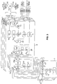
- the device according to the invention represented on the figure 2 , comprises a probe 1, basic modules 2, a synchro-sequencer module 3 and data processing means 4.
- the processing means 4 advantageously consist of a microcomputer.
- Each probe element 5 makes it possible to emit an ultrasonic signal in a material and to detect, in return, the signal refracted by this material.
- each probe element 5 is of the piezo-composite type.
- a base module 2 communicates with the following basic module 2 via a summing bus 100 of the five deviations managed by each base module 2.
- the data collected by each basic module 2 is transferred to the next basic module 2 via a data bus 110 consisting of a high-speed serial line.
- the last basic module 2 transfers all the data obtained to the data processing means 4, via the synchro-sequencer module 3, also via a data bus 110, consisting of a high-speed serial line. debit.
- the data processing means 4 communicate with each basic module 2, via the synchro-sequencer module 3, via an adjustment and configuration bus 130.
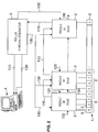
- a basic module 2 is shown in more detail on the figure 3 .
- Each basic module 2 comprises transmitting and receiving means 7, delay circuits 8, a processor 9 and a transfer multiplexer 10.
- Each basic module 2 comprises four times transmission and reception means 7, that is to say once per probe element 5.
- Each base module 2 has five times delay circuits 8, that is to say once per deflection.
- the transmission and reception means 7 comprise, for transmission, a transmitter memory 11, a digital-analog converter 12, an analog low-low filter 13 and an amplifier 14.
- the transmitting and receiving means 7 also comprise, for each probe element 5, for reception, a clipper 15, an analog filter 16, an analog digital converter 17 and a first digital interpolator 18 with parallel outputs.
- Each basic module 2 has the function of managing the four probe elements 5 of a group 6, as well as the emission of a composite wave corresponding to five different deviations I to V emitted by each probe element 5 of a group 6.
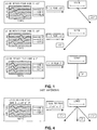
- emission curves are calculated during the initialization phase of the device according to the invention, with an accuracy ten times greater than the desired resolution.
- Each curve consists of the sum, according to emission delay laws, of the curves required for each of the five predetermined deviations of the ultrasonic beam emitted by a given group 6.
- the figure 4 illustrates, for three deviations (0 and plus or minus 45 degrees) the shape of the delay law, that is to say the amplitude of the signal emitted by each probe element 5 as a function of time.
- These curves also take into account the emission apodization coefficients intended to reduce the secondary lobes due to the spatial sampling of the probe 1.
- the precision of the calculation of the curves must be 0.5 nano-seconds.
- the sampling frequency H can, in turn, be limited to about three times the frequency of the probe 1, or 60MHz. This is sufficient for a correct reconstruction of the signal and has the advantage of limiting the material resources and therefore the cost of the device according to the invention. Working with the lowest possible H system frequency results in large delays with minimal hardware resources.
- each transmitter memory 11 is read at the sampling frequency H.
- the digital data corresponding to the recorded emission curves in each transmitter memory 11 of a channel corresponding to a given sensor element 5 are converted, also at the sampling frequency H, after their playback, into analog signals by the digital-to-analog converter 12 of the same channel.
- the analog signal obtained is then filtered by the corresponding analog low-low filter 13, so as to reject the high frequency components due to the sampling.
- the filtered signal is then amplified by the corresponding amplifier 14.
- This amplifier 14 is a linear power amplifier for supplying the energy required for the excitation of a probe element 5.
- the signals emitted by the different probe elements 5 in the material are refracted by the latter. These refracted signals are collected by each element of probe 5.
- the limiter 15 protects the circuit elements 16, 17, 18 at the input of the signals collected.
- the analog filter 16 filters the signals to let only the frequency components of the useful band. Finally, they are converted, at the frequency H / n, by the analog-digital converter 17, with a minimum dynamic of 14 bits. This makes it possible to obtain sufficient input dynamics to avoid any analog gain control at the input, as well as any saturation phenomenon. This dynamic is also sufficient to deal with any of the deviations.
- the first interpolator 18 performs, on the output signal of the digital analog converter 17, a digital filter interpolation, so as to obtain the temporal resolution necessary for the accuracy of the desired delay to perform the various deviations considered.
- the system frequency H is, as we have seen previously, equal to about three times the frequency of the probe 1. This would not be sufficient to obtain the necessary resolution on the first delay cells 19 constituting the circuits. delay 8 and located downstream of the analog-digital converter 17, because this resolution is set at one-tenth of the wavelength.
- the first interpolator 18 makes it possible to solve this problem by multiplying by four the temporal resolution, without increasing the system frequency H.
- the resolution of the delay circuits of the delay circuits 8 is of the order of four nano-seconds.
- the delay circuits 8 comprise, for each deviation I to V, a first delay cell 19, a first summer 20, a second delay cell 21, a second adder 22, and a multiplier circuit 23 and processing modules for operation 24, 24a.
- the first delay cell 19 manages the delays in a group 6 of four probe elements 5.
- Each first delay cell 19 consists of a multiplexer 25, a first circular buffer circuit 26 and a first divider circuit 26a.
- the multiplexer 25 selects the signals from the transmitting and receiving means 7 for each probe element 5 with the resolution of the tenth of a wavelength.
- the circular buffer circuit 26 applies a delay to each selected signal.
- the circular buffer circuit 26 makes it possible to obtain delays of several wavelengths while working at the frequency H / n.
- the first divider circuit 26a performs a reception apodization which reduces the sidelobes due to the spatial sampling of the probe 1.
- the first delay cell 19 is dynamically driven on writing by a first memory circuit 27 and a second interpolator 28.
- the first memory circuit 27 stores, in the initialization phase, the characteristic points of the delay curve of the element of corresponding probe 5.
- the second interpolator 28 regenerates the intermediate points at these characteristic points.
- the first delay cell 19 has a resolution of the order of one-tenth of the wavelength.
- the first summator 20 adds the signals from the first delay cells 19 of each probe element 5 of a group 6 after they have been phased by the delays applied thereto by the delay cells 19.
- Each second delay cell 21 comprises a second circular buffer circuit 29. Each second delay cell 21 manages the delays between the groups 6. These delays can reach several hundred wavelengths. Each delay cell 21 is dynamically driven on writing by a second memory circuit 30 and a third interpolator 31.
- the second memory circuit 30 stores, during the initialization phase of the device according to the invention, the characteristic points of the curve. Each third interpolator 31 regenerates the intermediate points at the characteristic points.
- the second delay cell 21 functions, like the first delay cell 19, at the frequency H / n.
- the second delay cell 21a has a resolution of one third of the wavelength.
- the second adder 22 adds the signals of a group 6, with the signals from the previous group.
- serial link The data transmission for summation, by the second summator 22, between groups 6, is performed by high speed serial link through a serializer 32 and a deserializer 32a.
- serial links can convey speeds of the order of 1.5 Gb / s.
- deserializers are of the LVDS type (LVDS is the acronym for the English expression “Low Voltage Differential Signaling” which translates to "low voltage differential signaling”). These arrangements make it possible to keep all the bits added by the first 20 and second summers and thus to have a perfectly linear processing chain, with an output dynamic range of between 96 dB and 132 dB, for a probe 1 of 8 to 2043 elements. probe 5.
- the signal resulting from the summation by the second adder 22 is applied to a gain by the multiplier circuit 23.
- the multiplier circuit 23 is dynamically driven by a third memory circuit 33 and a fourth interpolator 34.
- the third memory circuit 33 stores the characteristic points of a gain curve. This gain curve has been stored in the third memory circuit 33 during the initialization phase.
- the fourth interpolator 34 generates the intermediate points between the characteristic points of the gain curve stored in the third memory circuit 33.
- a fifth digital interpolator makes it possible to recover the temporal resolution of the tenth of a wavelength without increasing the system frequency H. This resolution is sufficient to allow all the conventional treatments carried out by conventional control and monitoring devices. ultrasound imaging.
- the output data of the fifth interpolator 35 are processed by the processing modules for operation 24, 24a.
- These processing processing modules 24, 24a are advantageously respectively of the "echo display” (A-SCAN) and "amplitude and distance measurement in a selection window” (GATES) type.
- GATES selection window
- the signal resulting from the processing by the processing modules for operation 24, 24a is sent by the processor 9 and the transfer multiplexer 10, to the next basic module 2 or to the data processing means 4, via a serial link to broadband type LVDS.
- the device according to the invention allows the summation of signals out of phase from 0 to several hundred wavelengths, with a resolution of the order of one-tenth of a wavelength.
- each deviation can take any value in this range independently of the values of other deviations.
- the device according to the invention also authorizing the frequency coding of the signals transmitted for each deviation, the discrimination of the received signals is greatly improved.
- the range of phase shift is variable from 0 to about 10 microseconds, with a resolution of five nanoseconds.
- Delays are applied with sufficient accuracy so that over-sampling points can be dropped, so as to return to the volume and signal processing frequency, before interpolation by the first interpolator 18.
- the exemplary embodiment of the device presented above allows a fully real-time operation.
- the rate of acquisition and processing depends only on the travel time in the analyzed material, as in conventional single-channel control systems, which allows rates of several kilo-Hertz in the majority of applications.
- This device has no acquisition memory, which makes possible significant and unrestricted probing times, without any additional component cost for the analysis device.
- the device according to the invention can advantageously be associated with an overhead multiplexer which makes it possible to reduce substantially the overall cost of the analysis device.
- the use of digital delays allows angular deflections much higher than those obtained with analog circuits. Indeed, the accuracy of the digital circuits does not depend on the absolute value of the delay.
- the device according to the invention has a circular operation, that is to say that one can start and stop the transmission and the reception on any probe element 5.
- a composite wave is emitted composed of several signals emitted by all the probe elements 5 of the probe 1, with emission delay laws allowing the simultaneous emission of the wave according to several deviations.
- the delay circuits 8 then process the signals corresponding to the emitted wave, refracted by the material and collected by the probe elements 5, by applying, to these signals, reception delay laws corresponding to the different deviations.
- a composite wave is emitted composed of several signals emitted simultaneously by at least two different zones of the probe 1 each comprising several probe elements 5. Each of these zones then simultaneously scans the material at analyze, emitting the wave according to several deviations.
- the signals refracted by the material and collected by the probe elements 5, zone by zone, are then processed by applying to them reception delay laws corresponding to the different deviations of the emitted wave.
- This second example of a process is particularly advantageous.
- the scanning speed is divided by four. If, with each of the zones, the wave is transmitted according to five deviations, a factor of twenty is gained on the scanning speed of the material to be analyzed with respect to what could be obtained with the methods and devices of the prior art.
- the device and the method according to the invention apply, not exclusively, to all ultrasonic tests, namely, in the field of non-destructive testing, to portable devices and automatic systems, and in the medical field, to devices diagnosis.
- the device and method according to the invention also apply to all systems that use a sensor consisting of a plurality of independent elements, regardless of the physical phenomenon used: Foucault currents, infrasound, electromagnetic waves, etc.
- the device and method according to the invention also apply to all multi-element sensors, whether linear, matrix or circular.
Landscapes
- Physics & Mathematics (AREA)
- Health & Medical Sciences (AREA)
- Life Sciences & Earth Sciences (AREA)
- Chemical & Material Sciences (AREA)
- Analytical Chemistry (AREA)
- Biochemistry (AREA)
- General Health & Medical Sciences (AREA)
- General Physics & Mathematics (AREA)
- Immunology (AREA)
- Pathology (AREA)
- Acoustics & Sound (AREA)
- Investigating Or Analyzing Materials By The Use Of Ultrasonic Waves (AREA)
Applications Claiming Priority (3)
| Application Number | Priority Date | Filing Date | Title |
|---|---|---|---|
| FR0112516 | 2001-09-28 | ||
| FR0112516A FR2830328B1 (fr) | 2001-09-28 | 2001-09-28 | Dispositif et procede d'analyse de la structure d'un materiau |
| PCT/FR2002/003283 WO2003029808A1 (fr) | 2001-09-28 | 2002-09-26 | Dispositif et procede d'analyse de la structure d'un materiau |
Publications (2)
| Publication Number | Publication Date |
|---|---|
| EP1430299A1 EP1430299A1 (fr) | 2004-06-23 |
| EP1430299B1 true EP1430299B1 (fr) | 2017-11-08 |
Family
ID=8867720
Family Applications (1)
| Application Number | Title | Priority Date | Filing Date |
|---|---|---|---|
| EP02774930.8A Expired - Lifetime EP1430299B1 (fr) | 2001-09-28 | 2002-09-26 | Dispositif d'analyse de la structure d'un materiau |
Country Status (5)
| Country | Link |
|---|---|
| US (1) | US7181356B2 (enExample) |
| EP (1) | EP1430299B1 (enExample) |
| JP (1) | JP4426295B2 (enExample) |
| FR (1) | FR2830328B1 (enExample) |
| WO (1) | WO2003029808A1 (enExample) |
Families Citing this family (10)
| Publication number | Priority date | Publication date | Assignee | Title |
|---|---|---|---|---|
| FR2849368A1 (fr) * | 2002-12-30 | 2004-07-02 | Koninkl Philips Electronics Nv | Detection de defauts de petite taille en imagerie ultrasonore medicale |
| FR2855271B1 (fr) * | 2003-05-22 | 2006-01-21 | Jacques Dory | Procede pour l'exploration et l'analyse d'une structure volumique |
| US8257260B2 (en) * | 2004-06-28 | 2012-09-04 | Koninklijke Philips Electronics N.V. | System and method for amplifying transmit waveforms generated by an ultrasonic system |
| EP1798549A1 (de) | 2005-12-06 | 2007-06-20 | BAM Bundesanstalt für Materialforschung und -prüfung | Verfahren und Vorrichtung zur Ultraschalldetektion von Diskontinuitäten in einem Materialbereich |
| JP2011011366A (ja) * | 2009-06-30 | 2011-01-20 | Sumitomo Electric Ind Ltd | 金属積層構造体の製造方法 |
| US10025272B2 (en) | 2013-01-25 | 2018-07-17 | General Electric Company | Ultrasonic holography imaging system and method |
| US9639056B2 (en) | 2013-09-17 | 2017-05-02 | General Electric Company | Acoustical holography with multi-level square wave excitation signals |
| US10557832B2 (en) * | 2017-04-28 | 2020-02-11 | GM Global Technology Operations LLC | Portable acoustic apparatus for in-situ monitoring of a weld in a workpiece |
| FR3113135B1 (fr) | 2020-07-30 | 2022-07-01 | Socomate Int | Procédé de détection de discontinuités et système mettant en œuvre ce procédé |
| FR3153407A1 (fr) | 2023-09-25 | 2025-03-28 | Farès Abda | Systèmes et procédés de mesures par effet doppler à l’aide d’une architecture hexagonale optimale à géométrie fixe ou adaptative |
Citations (2)
| Publication number | Priority date | Publication date | Assignee | Title |
|---|---|---|---|---|
| US4815043A (en) * | 1986-11-13 | 1989-03-21 | Kabushiki Kaisha Toshiba | Ultrasonic imaging apparatus |
| EP0335578A2 (en) * | 1988-03-28 | 1989-10-04 | Hewlett-Packard Company | Ultrasound imaging system utilizing two or more simultaneously-active apertures |
Family Cites Families (22)
| Publication number | Priority date | Publication date | Assignee | Title |
|---|---|---|---|---|
| US3936791A (en) * | 1973-09-13 | 1976-02-03 | The Commonwealth Of Australia | Linear array ultrasonic transducer |
| AU534828B2 (en) * | 1979-05-16 | 1984-02-16 | Yoshino Kogosho Co. Ltd. | Atomizer |
| US4371097A (en) * | 1980-05-07 | 1983-02-01 | Diamond International Corporation | Liquid dispensing pump |
| EP0059745B1 (de) * | 1980-09-10 | 1985-12-04 | Gewertec Gesellschaft Für Werkstofftechnik Mbh | Verfahren und vorrichtung zur schallemissions-ortung und -analyse |
| DE3315334A1 (de) * | 1983-04-28 | 1984-10-31 | Pfeiffer Erich Gmbh & Co Kg | Zerstaeuber- oder dosierpumpe |
| JPS59225374A (ja) * | 1983-06-06 | 1984-12-18 | Hitachi Ltd | 音源位置標定方法とその装置 |
| US4835478A (en) * | 1987-02-17 | 1989-05-30 | Haddon Merrill K | Method and apparatus for acoustic detection of faults in underground cables |
| US5010503A (en) * | 1988-04-20 | 1991-04-23 | Institut Elektrosvarki Imeni E.O. Patona Akademii Nauk Ukrainskoi Ssr | Apparatus for acoustic-emission inspection of articles |
| FR2631707B1 (fr) * | 1988-05-20 | 1991-11-29 | Labo Electronique Physique | Echographe ultrasonore a coherence de phase controlable |
| JP3322694B2 (ja) * | 1992-05-25 | 2002-09-09 | 株式会社日立メディコ | 超音波撮像装置 |
| US5581037A (en) * | 1992-11-06 | 1996-12-03 | Southwest Research Institute | Nondestructive evaluation of pipes and tubes using magnetostrictive sensors |
| US5456113A (en) * | 1992-11-06 | 1995-10-10 | Southwest Research Institute | Nondestructive evaluation of ferromagnetic cables and ropes using magnetostrictively induced acoustic/ultrasonic waves and magnetostrictively detected acoustic emissions |
| US5351863A (en) * | 1993-03-08 | 1994-10-04 | Dupont Industries, Inc. | Manually-operated dispensing pump |
| FR2718372B1 (fr) * | 1994-04-08 | 1996-06-28 | Sofab | Dispensateur de produits fluides. |
| US5487306A (en) * | 1994-09-26 | 1996-01-30 | General Electric Company | Phase aberration correction in phased-array imaging systems |
| US6050457A (en) * | 1995-12-06 | 2000-04-18 | The Procter & Gamble Company | High pressure manually-actuated spray pump |
| DE19602811C1 (de) * | 1996-01-26 | 1997-06-12 | Siemens Ag | Vefahren zur Ortung von Körperschallereignissen bei zu überwachenden Druckumschließungen in Kraftwerken |
| DE19604348C2 (de) * | 1996-02-07 | 2003-10-23 | Deutsche Telekom Ag | Verfahren zur Herstellung einer kalibrierten Längenskala im Nanometerbereich für technische Geräte, die der hochauflösenden bis ultrahochauflösenden Abbildung von Strukturen dienen |
| US20020158212A1 (en) * | 1998-04-17 | 2002-10-31 | French Todd E. | Apparatus and methods for time-resolved optical spectroscopy |
| DE19840721A1 (de) * | 1998-09-07 | 2000-03-09 | Pfeiffer Erich Gmbh & Co Kg | Spender für Medien |
| US6741524B2 (en) * | 1999-12-28 | 2004-05-25 | Kabushiki Kaisha Toshiba | Thermally-assisted magnetic recording and reproducing device having an electron beam thermal source |
| US6490533B2 (en) * | 2001-04-26 | 2002-12-03 | Affymetrix, Inc. | System, method, and product for dynamic noise reduction in scanning of biological materials |
-
2001
- 2001-09-28 FR FR0112516A patent/FR2830328B1/fr not_active Expired - Lifetime
-
2002
- 2002-09-26 EP EP02774930.8A patent/EP1430299B1/fr not_active Expired - Lifetime
- 2002-09-26 WO PCT/FR2002/003283 patent/WO2003029808A1/fr not_active Ceased
- 2002-09-26 US US10/490,513 patent/US7181356B2/en not_active Expired - Lifetime
- 2002-09-26 JP JP2003532970A patent/JP4426295B2/ja not_active Expired - Lifetime
Patent Citations (2)
| Publication number | Priority date | Publication date | Assignee | Title |
|---|---|---|---|---|
| US4815043A (en) * | 1986-11-13 | 1989-03-21 | Kabushiki Kaisha Toshiba | Ultrasonic imaging apparatus |
| EP0335578A2 (en) * | 1988-03-28 | 1989-10-04 | Hewlett-Packard Company | Ultrasound imaging system utilizing two or more simultaneously-active apertures |
Non-Patent Citations (1)
| Title |
|---|
| MALLART R.: "IMPROVED IMAGING RATE THROUGH SIMULTANEOUS TRANSMISSION OF SEVERAL ULTRASOUND BEAMS", ROCEEDINGS OF THE SPIE, SPIE, BELLINGHAM, VA, US, vol. 1733, 1992, pages 120 - 130, XP007903874 * |
Also Published As
| Publication number | Publication date |
|---|---|
| FR2830328A1 (fr) | 2003-04-04 |
| US7181356B2 (en) | 2007-02-20 |
| WO2003029808A1 (fr) | 2003-04-10 |
| JP4426295B2 (ja) | 2010-03-03 |
| EP1430299A1 (fr) | 2004-06-23 |
| FR2830328B1 (fr) | 2003-12-05 |
| JP2005504319A (ja) | 2005-02-10 |
| US20040249589A1 (en) | 2004-12-09 |
Similar Documents
| Publication | Publication Date | Title |
|---|---|---|
| EP0904535B1 (fr) | Procede et dispositif de detection et de localisation de source sonore reflechissante | |
| EP0640845B1 (fr) | Procédé de détermination à distance de la vitesse tridimensionnelle d'un fluide tel que l'air ou l'eau | |
| EP0541434B1 (fr) | Procédé et dispositif de contrÔle interne de pièces par ultrasons | |
| FR2851662A1 (fr) | Procede et dispositif de detection de discontinuites dans un milieu | |
| EP1430299B1 (fr) | Dispositif d'analyse de la structure d'un materiau | |
| EP0459583B1 (fr) | Echographe ultrasonore à correction adaptative d'aberration de phase | |
| EP0872742B1 (fr) | Procédé et dispositif pour le traitement de signaux représentatifs d'ondes réfléchies, transmises ou réfractées par une structure volumique en vue d'effectuer une exploration et une analyse de cette structure | |
| EP0709673A1 (fr) | Dispositif de contrÔle non destructif d'objets tubulaires creux par ultrasons | |
| WO1995026160A1 (fr) | Procede et dispositif d'evaluation et de caracterisation des proprietes des os | |
| EP0124442B1 (fr) | Procédé et dispositif d'holographie acoustique utilisant un faisceau ultrasonore limité dans l'espace | |
| FR2586820A1 (fr) | Systeme de mesure du coefficient de reflexion acoustique de reflecteurs immerges. | |
| EP0562939A1 (fr) | Dispositif et méthode d'exploration sismique | |
| FR2523326A1 (fr) | Appareil de formation d'images par ultrasons | |
| FR2570837A1 (fr) | Sonde a ultrasons pour balayage sectoriel electronique et echographe incorporant une telle sonde | |
| EP0164808A1 (fr) | Appareil d'examen de milieux par échographie ultrasonore | |
| EP0825453A1 (fr) | Procédé et dispositif pour le traitement de signaux représentatifs d'ondes réfléchies ou transmises par une structure volumique en vue d'effectuer une exploration et une analyse de cette structure | |
| EP0463964B2 (fr) | Système d'émission-réception d'ultrasons | |
| FR2530032A1 (fr) | Analyseur de frequence | |
| EP0197582A1 (fr) | Procédé et appareil d'exploration de milieux par échographie ultrasonore | |
| EP4189380B1 (fr) | Procédé de détection de discontinuités et système mettant en oeuvre ce procédé | |
| WO1982000061A1 (fr) | Dispositif recepteur pour echographe a sonde ultrasonore multi-elements et echographe ainsi equipe | |
| FR2562242A1 (fr) | Procede de dispositif d'identification de discontinuites dans un ecoulement par une technique ultrasonique | |
| FR2577323A1 (fr) | Procede de selection d'un signal acoustique et dispositif de selection correspondant | |
| FR2737011A1 (fr) | Procede et dispositif d'imagerie parallele | |
| FR2478321A1 (fr) | Systeme de traitement d'un signal acoustique de teledetection de vitesse du vent |
Legal Events
| Date | Code | Title | Description |
|---|---|---|---|
| PUAI | Public reference made under article 153(3) epc to a published international application that has entered the european phase |
Free format text: ORIGINAL CODE: 0009012 |
|
| 17P | Request for examination filed |
Effective date: 20040315 |
|
| AK | Designated contracting states |
Kind code of ref document: A1 Designated state(s): AT BE BG CH CY CZ DE DK EE ES FI FR GB GR IE IT LI LU MC NL PT SE SK TR |
|
| AX | Request for extension of the european patent |
Extension state: AL LT LV MK RO SI |
|
| 17Q | First examination report despatched |
Effective date: 20080206 |
|
| GRAP | Despatch of communication of intention to grant a patent |
Free format text: ORIGINAL CODE: EPIDOSNIGR1 |
|
| STAA | Information on the status of an ep patent application or granted ep patent |
Free format text: STATUS: GRANT OF PATENT IS INTENDED |
|
| RIC1 | Information provided on ipc code assigned before grant |
Ipc: G01S 15/89 20060101ALI20170619BHEP Ipc: G01N 29/26 20060101ALI20170619BHEP Ipc: G01N 29/06 20060101AFI20170619BHEP |
|
| INTG | Intention to grant announced |
Effective date: 20170706 |
|
| GRAS | Grant fee paid |
Free format text: ORIGINAL CODE: EPIDOSNIGR3 |
|
| GRAA | (expected) grant |
Free format text: ORIGINAL CODE: 0009210 |
|
| STAA | Information on the status of an ep patent application or granted ep patent |
Free format text: STATUS: THE PATENT HAS BEEN GRANTED |
|
| AK | Designated contracting states |
Kind code of ref document: B1 Designated state(s): AT BE BG CH CY CZ DE DK EE ES FI FR GB GR IE IT LI LU MC NL PT SE SK TR |
|
| REG | Reference to a national code |
Ref country code: GB Ref legal event code: FG4D Free format text: NOT ENGLISH |
|
| REG | Reference to a national code |
Ref country code: CH Ref legal event code: EP Ref country code: AT Ref legal event code: REF Ref document number: 944615 Country of ref document: AT Kind code of ref document: T Effective date: 20171115 |
|
| REG | Reference to a national code |
Ref country code: IE Ref legal event code: FG4D Free format text: LANGUAGE OF EP DOCUMENT: FRENCH |
|
| REG | Reference to a national code |
Ref country code: DE Ref legal event code: R096 Ref document number: 60249162 Country of ref document: DE |
|
| REG | Reference to a national code |
Ref country code: SE Ref legal event code: TRGR |
|
| REG | Reference to a national code |
Ref country code: NL Ref legal event code: MP Effective date: 20171108 |
|
| REG | Reference to a national code |
Ref country code: AT Ref legal event code: MK05 Ref document number: 944615 Country of ref document: AT Kind code of ref document: T Effective date: 20171108 |
|
| PG25 | Lapsed in a contracting state [announced via postgrant information from national office to epo] |
Ref country code: FI Free format text: LAPSE BECAUSE OF FAILURE TO SUBMIT A TRANSLATION OF THE DESCRIPTION OR TO PAY THE FEE WITHIN THE PRESCRIBED TIME-LIMIT Effective date: 20171108 Ref country code: NL Free format text: LAPSE BECAUSE OF FAILURE TO SUBMIT A TRANSLATION OF THE DESCRIPTION OR TO PAY THE FEE WITHIN THE PRESCRIBED TIME-LIMIT Effective date: 20171108 Ref country code: ES Free format text: LAPSE BECAUSE OF FAILURE TO SUBMIT A TRANSLATION OF THE DESCRIPTION OR TO PAY THE FEE WITHIN THE PRESCRIBED TIME-LIMIT Effective date: 20171108 |
|
| PG25 | Lapsed in a contracting state [announced via postgrant information from national office to epo] |
Ref country code: GR Free format text: LAPSE BECAUSE OF FAILURE TO SUBMIT A TRANSLATION OF THE DESCRIPTION OR TO PAY THE FEE WITHIN THE PRESCRIBED TIME-LIMIT Effective date: 20180209 Ref country code: BG Free format text: LAPSE BECAUSE OF FAILURE TO SUBMIT A TRANSLATION OF THE DESCRIPTION OR TO PAY THE FEE WITHIN THE PRESCRIBED TIME-LIMIT Effective date: 20180208 Ref country code: AT Free format text: LAPSE BECAUSE OF FAILURE TO SUBMIT A TRANSLATION OF THE DESCRIPTION OR TO PAY THE FEE WITHIN THE PRESCRIBED TIME-LIMIT Effective date: 20171108 |
|
| REG | Reference to a national code |
Ref country code: FR Ref legal event code: PLFP Year of fee payment: 17 |
|
| PG25 | Lapsed in a contracting state [announced via postgrant information from national office to epo] |
Ref country code: CZ Free format text: LAPSE BECAUSE OF FAILURE TO SUBMIT A TRANSLATION OF THE DESCRIPTION OR TO PAY THE FEE WITHIN THE PRESCRIBED TIME-LIMIT Effective date: 20171108 Ref country code: SK Free format text: LAPSE BECAUSE OF FAILURE TO SUBMIT A TRANSLATION OF THE DESCRIPTION OR TO PAY THE FEE WITHIN THE PRESCRIBED TIME-LIMIT Effective date: 20171108 Ref country code: CY Free format text: LAPSE BECAUSE OF FAILURE TO SUBMIT A TRANSLATION OF THE DESCRIPTION OR TO PAY THE FEE WITHIN THE PRESCRIBED TIME-LIMIT Effective date: 20171108 Ref country code: EE Free format text: LAPSE BECAUSE OF FAILURE TO SUBMIT A TRANSLATION OF THE DESCRIPTION OR TO PAY THE FEE WITHIN THE PRESCRIBED TIME-LIMIT Effective date: 20171108 Ref country code: DK Free format text: LAPSE BECAUSE OF FAILURE TO SUBMIT A TRANSLATION OF THE DESCRIPTION OR TO PAY THE FEE WITHIN THE PRESCRIBED TIME-LIMIT Effective date: 20171108 |
|
| REG | Reference to a national code |
Ref country code: DE Ref legal event code: R097 Ref document number: 60249162 Country of ref document: DE |
|
| PG25 | Lapsed in a contracting state [announced via postgrant information from national office to epo] |
Ref country code: IT Free format text: LAPSE BECAUSE OF FAILURE TO SUBMIT A TRANSLATION OF THE DESCRIPTION OR TO PAY THE FEE WITHIN THE PRESCRIBED TIME-LIMIT Effective date: 20171108 |
|
| PLBE | No opposition filed within time limit |
Free format text: ORIGINAL CODE: 0009261 |
|
| STAA | Information on the status of an ep patent application or granted ep patent |
Free format text: STATUS: NO OPPOSITION FILED WITHIN TIME LIMIT |
|
| 26N | No opposition filed |
Effective date: 20180809 |
|
| PG25 | Lapsed in a contracting state [announced via postgrant information from national office to epo] |
Ref country code: MC Free format text: LAPSE BECAUSE OF FAILURE TO SUBMIT A TRANSLATION OF THE DESCRIPTION OR TO PAY THE FEE WITHIN THE PRESCRIBED TIME-LIMIT Effective date: 20171108 |
|
| REG | Reference to a national code |
Ref country code: CH Ref legal event code: PL |
|
| REG | Reference to a national code |
Ref country code: BE Ref legal event code: MM Effective date: 20180930 |
|
| REG | Reference to a national code |
Ref country code: IE Ref legal event code: MM4A |
|
| PG25 | Lapsed in a contracting state [announced via postgrant information from national office to epo] |
Ref country code: LU Free format text: LAPSE BECAUSE OF NON-PAYMENT OF DUE FEES Effective date: 20180926 |
|
| PG25 | Lapsed in a contracting state [announced via postgrant information from national office to epo] |
Ref country code: IE Free format text: LAPSE BECAUSE OF NON-PAYMENT OF DUE FEES Effective date: 20180926 |
|
| PG25 | Lapsed in a contracting state [announced via postgrant information from national office to epo] |
Ref country code: CH Free format text: LAPSE BECAUSE OF NON-PAYMENT OF DUE FEES Effective date: 20180930 Ref country code: LI Free format text: LAPSE BECAUSE OF NON-PAYMENT OF DUE FEES Effective date: 20180930 Ref country code: BE Free format text: LAPSE BECAUSE OF NON-PAYMENT OF DUE FEES Effective date: 20180930 |
|
| PG25 | Lapsed in a contracting state [announced via postgrant information from national office to epo] |
Ref country code: TR Free format text: LAPSE BECAUSE OF FAILURE TO SUBMIT A TRANSLATION OF THE DESCRIPTION OR TO PAY THE FEE WITHIN THE PRESCRIBED TIME-LIMIT Effective date: 20171108 |
|
| PG25 | Lapsed in a contracting state [announced via postgrant information from national office to epo] |
Ref country code: PT Free format text: LAPSE BECAUSE OF FAILURE TO SUBMIT A TRANSLATION OF THE DESCRIPTION OR TO PAY THE FEE WITHIN THE PRESCRIBED TIME-LIMIT Effective date: 20171108 |
|
| PGFP | Annual fee paid to national office [announced via postgrant information from national office to epo] |
Ref country code: FR Payment date: 20210729 Year of fee payment: 20 |
|
| PGFP | Annual fee paid to national office [announced via postgrant information from national office to epo] |
Ref country code: GB Payment date: 20210928 Year of fee payment: 20 Ref country code: SE Payment date: 20210916 Year of fee payment: 20 Ref country code: DE Payment date: 20210908 Year of fee payment: 20 |
|
| REG | Reference to a national code |
Ref country code: DE Ref legal event code: R071 Ref document number: 60249162 Country of ref document: DE |
|
| REG | Reference to a national code |
Ref country code: GB Ref legal event code: PE20 Expiry date: 20220925 |
|
| PG25 | Lapsed in a contracting state [announced via postgrant information from national office to epo] |
Ref country code: GB Free format text: LAPSE BECAUSE OF EXPIRATION OF PROTECTION Effective date: 20220925 |