EP1427563B2 - Vorrichtung zur substratbehandlung mittels laserstrahlung - Google Patents
Vorrichtung zur substratbehandlung mittels laserstrahlung Download PDFInfo
- Publication number
- EP1427563B2 EP1427563B2 EP02779434A EP02779434A EP1427563B2 EP 1427563 B2 EP1427563 B2 EP 1427563B2 EP 02779434 A EP02779434 A EP 02779434A EP 02779434 A EP02779434 A EP 02779434A EP 1427563 B2 EP1427563 B2 EP 1427563B2
- Authority
- EP
- European Patent Office
- Prior art keywords
- polygonal mirror
- rotatable polygonal
- another
- laser beam
- converging lenses
- Prior art date
- Legal status (The legal status is an assumption and is not a legal conclusion. Google has not performed a legal analysis and makes no representation as to the accuracy of the status listed.)
- Expired - Lifetime
Links
Images

Classifications
-
- B—PERFORMING OPERATIONS; TRANSPORTING
- B23—MACHINE TOOLS; METAL-WORKING NOT OTHERWISE PROVIDED FOR
- B23K—SOLDERING OR UNSOLDERING; WELDING; CLADDING OR PLATING BY SOLDERING OR WELDING; CUTTING BY APPLYING HEAT LOCALLY, e.g. FLAME CUTTING; WORKING BY LASER BEAM
- B23K26/00—Working by laser beam, e.g. welding, cutting or boring
- B23K26/02—Positioning or observing the workpiece, e.g. with respect to the point of impact; Aligning, aiming or focusing the laser beam
- B23K26/06—Shaping the laser beam, e.g. by masks or multi-focusing
- B23K26/067—Dividing the beam into multiple beams, e.g. multifocusing
- B23K26/0676—Dividing the beam into multiple beams, e.g. multifocusing into dependently operating sub-beams, e.g. an array of spots with fixed spatial relationship or for performing simultaneously identical operations
-
- B—PERFORMING OPERATIONS; TRANSPORTING
- B23—MACHINE TOOLS; METAL-WORKING NOT OTHERWISE PROVIDED FOR
- B23K—SOLDERING OR UNSOLDERING; WELDING; CLADDING OR PLATING BY SOLDERING OR WELDING; CUTTING BY APPLYING HEAT LOCALLY, e.g. FLAME CUTTING; WORKING BY LASER BEAM
- B23K26/00—Working by laser beam, e.g. welding, cutting or boring
- B23K26/02—Positioning or observing the workpiece, e.g. with respect to the point of impact; Aligning, aiming or focusing the laser beam
- B23K26/06—Shaping the laser beam, e.g. by masks or multi-focusing
- B23K26/067—Dividing the beam into multiple beams, e.g. multifocusing
-
- B—PERFORMING OPERATIONS; TRANSPORTING
- B23—MACHINE TOOLS; METAL-WORKING NOT OTHERWISE PROVIDED FOR
- B23K—SOLDERING OR UNSOLDERING; WELDING; CLADDING OR PLATING BY SOLDERING OR WELDING; CUTTING BY APPLYING HEAT LOCALLY, e.g. FLAME CUTTING; WORKING BY LASER BEAM
- B23K26/00—Working by laser beam, e.g. welding, cutting or boring
- B23K26/08—Devices involving relative movement between laser beam and workpiece
- B23K26/082—Scanning systems, i.e. devices involving movement of the laser beam relative to the laser head
- B23K26/0821—Scanning systems, i.e. devices involving movement of the laser beam relative to the laser head using multifaceted mirrors, e.g. polygonal mirror
-
- B—PERFORMING OPERATIONS; TRANSPORTING
- B23—MACHINE TOOLS; METAL-WORKING NOT OTHERWISE PROVIDED FOR
- B23K—SOLDERING OR UNSOLDERING; WELDING; CLADDING OR PLATING BY SOLDERING OR WELDING; CUTTING BY APPLYING HEAT LOCALLY, e.g. FLAME CUTTING; WORKING BY LASER BEAM
- B23K26/00—Working by laser beam, e.g. welding, cutting or boring
- B23K26/08—Devices involving relative movement between laser beam and workpiece
- B23K26/083—Devices involving movement of the workpiece in at least one axial direction
- B23K26/0838—Devices involving movement of the workpiece in at least one axial direction by using an endless conveyor belt
- B23K26/0846—Devices involving movement of the workpiece in at least one axial direction by using an endless conveyor belt for moving elongated workpieces longitudinally, e.g. wire or strip material
-
- B—PERFORMING OPERATIONS; TRANSPORTING
- B23—MACHINE TOOLS; METAL-WORKING NOT OTHERWISE PROVIDED FOR
- B23K—SOLDERING OR UNSOLDERING; WELDING; CLADDING OR PLATING BY SOLDERING OR WELDING; CUTTING BY APPLYING HEAT LOCALLY, e.g. FLAME CUTTING; WORKING BY LASER BEAM
- B23K26/00—Working by laser beam, e.g. welding, cutting or boring
- B23K26/36—Removing material
- B23K26/38—Removing material by boring or cutting
-
- G—PHYSICS
- G02—OPTICS
- G02B—OPTICAL ELEMENTS, SYSTEMS OR APPARATUS
- G02B26/00—Optical devices or arrangements for the control of light using movable or deformable optical elements
- G02B26/08—Optical devices or arrangements for the control of light using movable or deformable optical elements for controlling the direction of light
- G02B26/10—Scanning systems
- G02B26/12—Scanning systems using multifaceted mirrors
- G02B26/123—Multibeam scanners, e.g. using multiple light sources or beam splitters
-
- G—PHYSICS
- G02—OPTICS
- G02B—OPTICAL ELEMENTS, SYSTEMS OR APPARATUS
- G02B5/00—Optical elements other than lenses
- G02B5/08—Mirrors
- G02B5/09—Multifaceted or polygonal mirrors, e.g. polygonal scanning mirrors; Fresnel mirrors
Definitions
- the invention relates to a device for substrate treatment by means of laser radiation, with a polygonal rotating mirror through which at least one incident laser beam is reflected and is pivotable via an array of juxtaposed converging lenses, which are arranged at a distance corresponding to their focal length from the substrate.
- Such a device is used in particular for processing, for example, strip-shaped materials by means of laser radiation, wherein the laser light is divided into a plurality of quasi-simultaneous processing stations and at the same time short pulses of very high frequency are generated from the continuous light of the laser.
- the high pulse repetition rate results in correspondingly high processing speeds.
- Beam splitting by so-called beam splitters would be disadvantageous insofar as the resulting partial beams would have a correspondingly lower intensity, which is not sufficient for certain processing methods. Moreover, the partial beams would also be an alternating, d. H. in any case have different intensity and / or spatial intensity distribution. Thus, the main problem with beam splitters is often the different influencing of the beam profile, especially in the case of contamination (beam geometry).
- Devices of the type mentioned in the introduction are used in particular for perforating thin papers such as cigarette mouth paper.
- the device generates a track of small holes per machining head, the continuous light of the laser being chopped into pulsed individual beams with the aid of an optical multiplexer.
- Each focused laser pulse abruptly vaporizes the thin material and thus creates a hole with a common diameter of, for example, about 60 to about 150 microns.
- a relevant device may, for. B. have 16 processing heads and thus perforate paper with, for example, four perforation zones, each with four rows of holes and a matching width of about 150 mm at several 100 m / min web speed. The perforation is therefore concentrated on a few zones across the web and arranged very densely in the longitudinal direction.
- the elaborate conversion to a polygon has hitherto been selected, the laser light being irradiated only to the z.
- the invention is generally based on the object of specifying a device in the preamble of Anspuchs 1, while maintaining a uniform size of the treated areas or hole size and optimal, even use of laser energy in a simple and fast way the number of individual locks of treatment sites or perforation is variable.
- An object of the invention is to provide an improved apparatus of the type mentioned above, which allows a reduced change of the number of facets and according to the sweep or fan angle of the reflected laser beam with a minimum of effort. In this case, a respective change should be possible in particular during operation of the device.
- the polygonal rotating mirror can be adjustable in particular by means of a motorized or manually operable positioning device.
- a different number of facets having areas in the direction of the axis of rotation of the polygonal rotating mirror are arranged one behind the other and that the polygonal rotating mirror is adjustable in the direction of this axis of rotation.
- the rotating polygonal mirror can be composed, for example, of disks through which the areas having a different number of facets are formed.
- the invention is further characterized in that the incident laser beam is focused by a lens on the rotating polygon mirror and that between the polygonal rotating mirror and the arrangement of at a precise or approximately its focal distance from the substrate arranged adjacent collecting lenses another Arrangement of juxtaposed collecting lenses is provided, which are arranged in an exact or approximately their focal length corresponding distance from the rotating polygonal mirror.
- the lenses between which the polygonal rotating mirror is located z. B. spherical and / or cylindrical collecting lenses.
- Spherical lenses have the advantage that the required reflection surface / width on the polygon and thus the weight and correspondingly the inertia can be kept small.
- Deflection mirrors may be arranged between the two arrangements of adjacent converging lenses.
- the axis of rotation of the polygonal rotating mirror or of a respective mirror area is tilted with respect to the plane perpendicular to the incident laser beam.
- a special polygon mirror which is divided into different areas and in each of these areas has a different number of facets, can thus via a motor or manual positioning practically during operation, eg. For example, within seconds, the fan angle of the beam multiplexer adjusted and thus, so to speak, at the push of a button, a different number of perforation beams are set with simultaneous use of the laser energy.
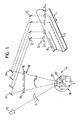
- FIGS. 1 and 2 show in a schematic, simplified representation of an apparatus for treating a substrate 10, here a moving in the transport direction L web such as in particular a packaging film or a paper web, by means of laser radiation.
- a substrate 10 here a moving in the transport direction L web such as in particular a packaging film or a paper web
- the light beam coming from a laser 12 passes through an entrance or converging lens 14 whose focal point or line is located on a surface of a polygon rotating mirror 16 arranged in the beam path behind the converging lens 14.
- the polygonal rotating mirror 16 is in several, here For example, two regions 16 ', 16 "having a different number of facets are subdivided In the present case, region 16' has four facets, for example, and region 16" has eight facets.
- the polygonal turning mirror 16 is adjustable so that the different regions 16 'and 16 "can be introduced into the beam path of the laser radiation, and correspondingly different sweep or fan angles of the laser beam reflected by the polygon rotating mirror 16 can be set Turning mirror 16 adjustable in particular by means of a motorized or manually operable positioning.
- the regions 16 ', 16 "having a different number of facets are arranged one behind the other in the direction of the axis of rotation A of the polygonal rotary mirror 16.
- the polygonal rotary mirror 16 can be adjusted in the direction of this axis of rotation A.
- the polygonal turning mirror 16 may for example be composed of disks through which the areas 16 ', 16 "having a different number of facets are formed, but in principle also an integral embodiment of the rotating polygonal mirror 16 is conceivable.
- the area 16 ' has for example four and the area 16 "has for example eight facets.
- a different number of facets is possible. It also depends on the speed achievable with the polygonal turning mirror 16 for a given chopping frequency. For example, different facet numbers and the same maximum speed are used in practice for the same polygon diameter.
- An important criterion in the choice of facet number is the desired fan angle, i. the desired single beam number equal to the number of perforation tracks.
- the converging lenses 18 1 - 18 n having the same focal length are arranged so that their focal point or their focal plane coincide approximately or exactly with the focal point or the focal plane of the converging lens 14 on the rotating polygonal mirror 16.
- the light leaving the collecting lenses 18 1 - 18 n is therefore again directed approximately parallel.
- the converging lens 14 and the converging lenses 18 1 - 18 n may be provided, for example, as spherical and / or cylindrical lenses.
- the light beams leaving the lens arrangement 18 are directed via deflecting mirrors 20, 22 to an arrangement of juxtaposed focusing or converging lenses 24 1 - 24 n , which are arranged at a distance from the substrate 10 which is approximately at their focal length.
- this lens arrangement 24 preferably comprises spherical collecting lenses 24 1 - 24 n , which focus the incident on them parallel light beams on the lying in the beam path behind the lens system 24 substrate 10.
- the size of the individual lenses 24 1 - 24 n of the lens system 24 preferably corresponds to the size of the individual lenses 18 1 - 18 n of the lens system 18, so that each lens portion of the lenses 18 1 - 18 n associated with a corresponding portion of the lenses 24 1 - 24 n ,
- the number of collecting lenses 18 1 - 18 n , deflecting mirror 20, deflecting mirror 22 and converging lenses 24 1 - 24 n each sixteen.
- the polygonal rotating mirror 16 assumes such a position that the incident laser beam impinges on the region 16 'of the polygonal rotating mirror 16, which here has four facets, for example. All sixteen collector lenses 18 1 - 18 n and deflecting mirror 20 are covered here. Accordingly, sixteen perforation traces 26 result in the substrate 10.
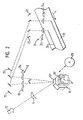
- the polygonal rotating mirror 16 is positioned so that the incident laser beam impinges on the area 16 "having, for example, eight facets, so that in the present case only eight converging lenses 18 1 -18 n and eight deflecting mirrors 20 are swept over so that Substrate 10 corresponding to only eight perforation traces 26 result.
- the polygonal rotating mirror 16 can be adjusted accordingly, for example by means of a motor drive 28.
- the areas 16 ', 16 "having a different number of facets may be provided on a common axis A.
- FIG. 3 shows in an enlarged view another embodiment of a two areas 16 ', 16 "different facets number having polygon rotating mirror 16. In the present case, a significantly higher number of facets than in the previously described embodiments is provided.
- the two areas 16 ', 16 are again on a common axis. be driven by separate drives.
Landscapes
- Physics & Mathematics (AREA)
- Optics & Photonics (AREA)
- Engineering & Computer Science (AREA)
- Plasma & Fusion (AREA)
- Mechanical Engineering (AREA)
- General Physics & Mathematics (AREA)
- Laser Beam Processing (AREA)
- Recrystallisation Techniques (AREA)
- Removal Of Insulation Or Armoring From Wires Or Cables (AREA)
Description
- Die Erfindung betrifft eine Vorrichtung zur Substratbehandlung mittels Laserstrahlung, mit einem Polygon-Drehspiegel, durch den wenigstens ein einfallender Laserstrahl reflektiert wird und über eine Anordnung von nebeneinander liegenden Sammellinsen schwenkbar ist, die in einem ihrer Brennweite entsprechenden Abstand vom Substrat angeordnet sind.
- Eine derartige Vorrichtung wird insbesondere zum Bearbeiten von beispielsweise bandförmigen Materialien mittels Laserstrahlung verwendet, wobei das Laserlicht in mehrere quasi-simultane Bearbeitungsstellen aufgeteilt und gleichzeitig aus dem Dauerlicht des Lasers kurze Pulse sehr hoher Frequenz erzeugt werden. Die hohe Pulswiederholungsrate resultiert in entsprechend hohen Bearbeitungsgeschwindigkeiten.
- Eine Strahlaufteilung durch sogenannte Strahlteiler wäre insoweit nachteilig, als die resultierenden Teilstrahlen eine entsprechend geringere Intensität aufweisen würden, die für bestimmte Bearbeitungsverfahren nicht ausreichend ist. Überdies würden die Teilstrahlen auch eine wechselnde, d. h. jedenfalls unterschiedliche Intensität und/oder räumliche Intensitätsverteilung aufweisen. So ist bei Strahlteilern häufig die unterschiedliche Beeinflussung des Strahlprofiles das Hauptproblem, insbesondere bei Verschmutzung (Strahlgeometrie).
- Beispielsweise bei der Perforierung von Papier mittels Laserlichtstrahlen ist es zur Erzielung einer gleichmäßigen Lochgröße und Güte unbedingt erforderlich, eine bestimmte, relativ hohe und gleichbleibende Intensität des die Perforation durchführenden Laserlichtstrahls sicherzustellen. Eine Strahlteilung wäre somit auch hier wieder ungünstig.
- Vorrichtungen der eingangs genannten Art (vgl. z. B.
DE-C-2918283 ) werden insbesondere zur Perforation von dünnen Papieren wie beispielsweise Zigarettenmundstückpapier verwendet. Dabei erzeugt die Vorrichtung pro Bearbeitungskopf jeweils eine Spur von kleinen Löchern, wobei das Dauerlicht des Lasers mit Hilfe eines optischen Multiplexers in gepulste Einzelstrahlen zerhackt wird. Jeder fokussierte Laserpuls verdampft schlagartig das dünne Material und erzeugt somit ein Loch mit einem üblichen Durchmesser von beispielsweise etwa 60 bis etwa 150 µm. Eine betreffende Vorrichtung kann z. B. 16 Bearbeitungsköpfe aufweisen und somit Papier mit beispielsweise vier Perforationszonen mit jeweils vier Lochreihen und einer dazu passenden Breite von etwa 150 mm bei mehreren 100 m/min Bahngeschwindigkeit perforieren. Die Perforation ist demnach auf wenige Zonen quer zur Bahn konzentriert und in Längsrichtung sehr dicht angeordnet. - In der Praxis ist es immer wieder erforderlich, die Anzahl von Facetten zu ändern. Dazu muß bisher das zusammen mit dem Antriebsmotor komplett montierte und gewuchtete Polygon ausgetauscht und das neue Polygon von neuem justiert werden. Dieser mehrere Stunden dauernde Vorgang ist für den Endkunden lästig, da nur erfahrenes und trainiertes Personal die betreffende fehlerträchtige Arbeit durchführen kann. In der Praxis führt dies dazu, daß ein Austausch des Polygones nur ungern und sehr selten durchgeführt wird.
- Mit einem jeweiligen Polygontausch und einer entsprechend veränderten Anzahl von Facetten kann nun aber der Überstreich- oder Fächerwinkel des reflektierten Laserstrahls und somit die Anzahl der belichteten und damit perforierenden Einzelstrahlen verändert werden. In der Regel geht es hierbei um die Optimierung der Produktionsgeschwindigkeit. Werden beispielsweise nur acht Strahlen, d. h. zum Beispiel acht Perforationsspuren, benötigt und ist die betreffende Maschine mit einem Polygon ausgestattet, das beispielsweise alle sechzehn vorhandenen Einzelpfade belichtet, müssen ohne Umbau auf ein entsprechend anderes Polygon gleich acht der sechzehn Strahlenpfade blockiert werden. Damit sind 50 % der ursprünglichen Laserenergie nicht für die Bearbeitung verfügbar. Zum Blockieren oder Unterdrücken einzelner Strahlen sind die bisher üblichen Perforationsmaschinen des entsprechenden Typs mit sogenannten Einzelstrahlverschlüssen oder Shuttern, d. h. zum Beispiel sechzehn solchen Shuttern, versehen.
- Falls die vom Endbenutzer zu produzierende Produktionsmenge sehr hoch ist und die für das betreffende Perforationsprodukt zur Verfügung stehende Produktionszeit beispielsweise mehrere Wochen beträgt, wird in der Praxis bisher der aufwendige Umbau auf ein Polygon gewählt, das Laserlicht nur auf die z. B. acht benötigten Strahlen auffächert, um die ganze zur Verfügung stehende Laserenergie auszunutzen.
- Der Erfindung liegt allgemein die Aufgabe zugrunde, eine Vorrichtung der im Oberbegriff des Anspuchs 1 anzugeben, bei der unter Aufrechterhaltung einer gleichmäßigen Größe der behandelten Stellen bzw. Lochgröße und optimaler, gleichmäßiger Ausnutzung der Laserenergie auf einfache und schnelle Weise die Anzahl der einzelnen Sperren von Behandlungsstellen bzw. Perforationsspuren varrierbar ist.
- Ein Ziel der Erfindung ist es, eine verbesserte Vorrichtung der eingangs genannten Art zu schaffen, die bei auf ein Minimum reduziertem Aufwand einen schnelleren Wechsel der Facettenanzahl und entsprechend des Überstreich- oder Fächerwinkels des reflektierten Laserstrahles gestattet. Dabei soll ein jeweiliger Wechsel insbesondere auch während des Betriebs der Vorrichtung möglich sein.
- Dieses Ziel wird erfindungsgemäß durch die Merkmale des Anspruchs 1 erreicht.
- Aufgrund dieser Ausbildung ist es bei minimalem Aufwand beispielsweise möglich, sehr schnell und praktisch während der Produktion zwischen zwei oder mehreren bezüglich ihrer Facettenzahl unterschiedlichen Polygonspiegelbereichen umzuschalten. Dabei kann der Polygon-Drehspiegel insbesondere mittels einer motorischen oder manuell betätigbaren Positioniereinrichtung verstellbar sein.
- Erfindungsgemäß sind die eine unterschiedliche Anzahl von Facetten aufweisenden Bereiche in Richtung der Drehachse des Polygon-Drehspiegels hintereinander angeordnet sind und daß der Polygon-Drehspiegel in Richtung dieser Drehachse verstellbar ist. Der Polygon-Drehspiegel kann beispielsweise aus Scheiben zusammengesetzt sein, durch die die eine unterschiedliche Anzahl von Facetten aufweisenden Bereiche gebildet sind. Es ergibt sich somit eine frei konfigurierbare Mehrfachpolygon-Optik, bei der beispielsweise entsprechend Hantelgewichten verschiedene Polygone kombiniert werden können. So können beispielsweise zwei oder drei oder noch mehr verschiedene Polygone miteinander kombiniert werden.
- Grundsätzlich ist jedoch auch eine einstückige Polygon-Drehspiegel-Ausführung denkbar, wobei die sich hinsichtlich ihrer Facettenanzahl unterschiedlichen Bereiche durch entsprechende Abschnitte dieses einstückigen Polygon-Drehspiegels gebildet sind.
- Die Erfindung zeichnet sich ferner dadurch aus, daß der einfallende Laserstrahl durch eine Linse auf den Polygon-Drehspiegel fokussiert wird und daß zwischen dem Polygon-Drehspiegel und der Anordnung von in einem genau oder ungefähr ihrer Brennweite entsprechenden Abstand vom Substrat angeordneten nebeneinander liegenden Sammellinsen eine weitere Anordnung von nebeneinander liegenden Sammellinsen vorgesehen ist, die in einem genau oder ungefähr ihrer Brennweite entsprechenden Abstand vom Polygon-Drehspiegel angeordnet sind.
- Die Linsen, zwischen denen der Polygon-Drehspiegel liegt, können z. B. sphärische und/oder zylindrische Sammellinsen sein. Dabei besitzen sphärische Linsen den Vorteil, daß die benötigte Reflexionsfläche /-breite auf dem Polygon und damit das Gewicht und entsprechend die Massenträgheit klein gehalten werden können.
- Zwischen den beiden Anordnungen von nebeneinanderliegenden Sammellinsen sind Umlenkspiegel angeordnet sein.
- In vielen Fällen ist es auch von Vorteil, wenn die Drehachse des Polygon-Drehspiegels bzw. eines jeweiligen Spiegelbereiches gegenüber der zum einfallenden Laserstrahl senkrechten Ebene verkippt ist.
- Mittels eines speziellen Polygonspiegels, der in verschiedene Bereiche unterteilt ist und in diesen Bereichen jeweils eine unterschiedliche Facettenanzahl aufweist, kann somit über eine motorische oder manuelle Positioniereinrichtung praktisch im laufenden Betrieb, z. B. innerhalb von Sekunden, der Fächerwinkel des Strahlenmultiplexers verstellt und somit sozusagen auf "Knopfdruck" eine andere Anzahl von Perforationsstrahlen bei gleichzeitiger Ausnutzung der Laserenergie eingestellt werden.
- Mit der Verwendung eines Polygon-Drehspiegels mit zumindest zwei eine unterschiedliche Anzahl von Facetten aufweisenden Bereichen ist insbesondere eine rasche Anpassung der belichteten und damit perforierenden Strahlengänge bzw. Perforationsspuren möglich.
- Die Erfindung wird im folgenden anhand eines Ausführungsbeispiels unter Bezugnahme auf die Zeichnung näher erläutert wobei die
Figuren 1 und2 lediglich der näheren Erläuterung der Erfindung dienen in dieser zeigen: - Fig. 1
- eine schematische, vereinfachte Darstellung einer Vorrichtung zur Substratbehandlung mittels Laserstrahlung, wobei der Polygon-Drehspiegel eine solche Position einnimmt, daß alle Umlenkspiegel überstrichen werden,
- Fig. 2
- die Vorrichtung gemäß
Figur 1 , wobei der Polygon-Drehspiegel jedoch eine solche Position einnimmt, daß nur ein Teil der Umlenkspiegel überstrichen wird, - Fig. 3
- eine vergrößerte Darstellung einer weiteren Ausführungsform eines zwei Bereiche unterschiedlicher Facettenanzahl aufweisenden Polygon-Drehspiegels der erfindungsgemäßen Vorrichtung.
- Die
Figuren 1 und2 zeigen in schematischer, vereinfachter Darstellung eine Vorrichtung zur Behandlung eines Substrats 10, hier einer in Transportrichtung L bewegten Materialbahn wie insbesondere einer Verpackungsfolie oder einer Papierbahn, mittels Laserstrahlung. Dabei durchläuft der von einem Laser 12 kommende Lichtstrahl eine Eintritts- oder Sammellinse 14, deren Brennpunkt bzw. Strichebene auf einer Fläche eines im Strahlengang hinter der Sammellinse 14 angeordneten Polygon-Drehspiegels 16 liegt. - Der Polygon-Drehspiegel 16 ist in mehrere, hier beispielsweise zwei eine unterschiedliche Anzahl von Facetten aufweisende Bereiche 16', 16" unterteilt. Im vorliegenden Fall besitzt der Bereich 16' beispielsweise vier Facetten und der Bereich 16" beispielsweise acht Facetten.
- Der Polygon-Drehspiegel 16 ist so verstellbar, daß die unterschiedlichen Bereiche 16' bzw. 16" in den Strahlengang der Laserstrahlung eingebracht werden können, und entsprechend unterschiedliche Überstreich- oder Fächerwinkel des vom Polygon-Drehspiegels 16 reflektierten Laserstrahls einstellbar sind. Hierbei ist der Polygon-Drehspiegel 16 insbesondere mittels einer motorischen oder manuell betätigbaren Positioniereinrichtung verstellbar.
- Wie anhand der
Figuren 1 und2 zu erkennen ist, sind die eine unterschiedliche Anzahl von Facetten aufweisenden Bereiche 16', 16" in Richtung der Drehachse A des Polygon-Drehspiegels 16 hintereinander angeordnet. Entsprechend ist der Polygon-Drehspiegel 16 in Richtung dieser Drehachse A verstellbar. - Der Polygon-Drehspiegel 16 kann beispielsweise aus Scheiben zusammengesetzt sein, durch die die eine unterschiedliche Anzahl von Facetten aufweisenden Bereichen 16', 16" gebildet sind. Grundsätzlich ist jedoch auch eine einstückige Ausführung des Polygon-Drehspiegels 16 denkbar.
- Im vorliegenden Fall besitzt der Bereich 16' beispielsweise vier und der Bereich 16" beispielsweise acht Facetten.
- Grundsätzlich ist jedoch auch eine andere Anzahl von Facetten möglich. Sie hängt für eine vorgegebene Zerhackungsfrequenz auch von der mit dem Polygon-Drehspiegel 16 erreichbaren Drehzahl ab. So verwendet man in der Praxis bei gleichem Polygondurchmesser verschiedene Facetten-Anzahlen und die gleiche maximale Drehzahl. Ein wichtiges Kriterium bei der Wahl der Facetten bzw. Facetten-Anzahl ist der gewünschte Fächerwinkel, d.h. die gewünschte Einzelstrahl-Anzahl, die gleich der Anzahl von Perforationsspuren ist.
- Bei sich drehendem Polygon-Drehspiegel 16 wird der einfallende, reflektierte Licht- bzw. Laserstrahl über eine Anordnung 18 von nebeneinander liegenden Kollimator- oder Sammellinsen 181 - 18n verschwenkt. Trifft der einfallende Laserstrahl auf die nächste Facette des Polygon-Drehspiegels 16, so springt der reflektierte Strahl zurück und überstreicht von neuem den betreffenden, die Sammellinsen 181 - 18n umfassenden Winkelbereich.
- Die eine gleiche Brennweite aufweisenden Sammellinsen 181 - 18n sind so angeordnet, daß ihr Brennpunkt beziehungsweise ihre Brennebene mit dem Brennpunkt beziehungsweise der Brennebene der Sammellinse 14 auf dem Polygon-Drehspiegel 16 ungefähr oder genau zusammenfällt. Das die Sammellinsen 181 - 18n verlassende Licht ist daher wieder annähernd parallel gerichtet.
- Die Sammellinse 14 und die Sammellinsen 181 - 18n können beispielsweise als sphärische und/oder zylindrische Linsen vorgesehen sein.
- Die die Linsenanordnung 18 verlassenden Lichtstrahlen werden beim vorliegenden Ausführungsbeispiel über Umlenkspiegel 20, 22 auf eine Anordnung von nebeneinander liegenden Fokussier- oder Sammellinsen 241 - 24n gerichtet, die in einem ungefähr ihrer Brennweite entsprechenden Abstand vom Substrat 10 angeordnet sind. Dabei umfaßt diese Linsenanordnung 24 vorzugsweise sphärische Sammellinsen 241 - 24n, die die auf sie auftreffenden parallelen Lichtstrahlen auf das im Strahlengang hinter dem Linsensystem 24 liegende Substrat 10 fokussieren. Die Größe der Einzellinsen 241 - 24n des Linsensystems 24 entspricht vorzugsweise der Größe der Einzellinsen 181 - 18n des Linsensystems 18, so daß jedem Linsenabschnitt der Linsen 181 - 18n ein entsprechender Abschnitt der Linsen 241 - 24n zugeordnet ist.
- Im vorliegenden Fall beträgt die Anzahl der Sammellinsen 181 - 18n, Umlenkspiegel 20, Umlenkspiegel 22 und Sammellinsen 241 - 24n jeweils sechzehn.
- In der Darstellung gemäß
Figur 1 nimmt der Polygon-Drehspiegel 16 eine solche Position ein, daß der einfallende Laserstrahl auf den hier beispielsweise vier Facetten aufweisenden Bereich 16' des Polygon-Drehspiegels 16 auftrifft. Es werden hier alle sechzehn Sammellinsen 181 - 18n und Umlenkspiegel 20 überstrichen. Entsprechend ergeben sich in dem Substrat 10 sechzehn Perforationsspuren 26. - In der Darstellung gemäß
Figur 2 ist der Polygon-Drehspiegel 16 dagegen so positioniert, daß der einfallende Laserstrahl auf den hier beispielsweise acht Facetten aufweisenden Bereich 16" auftrifft. Damit werden im vorliegenden Fall nur acht Sammellinsen 181 - 18n und acht Umlenkspiegel 20 überstrichen, so daß sich in dem Substrat 10 entsprechend nur acht Perforationsspuren 26 ergeben. - Wie anhand der
Figur 2 zu erkennen ist, kann der Polygon-Drehspiegel 16 beispielsweise mittels eines motorischen Antriebs 28 entsprechend verstellt werden. - Die eine unterschiedliche Anzahl von Facetten aufweisenden Bereiche 16', 16" können auf einer gemeinsamen Achse A vorgesehen sein.
-
Figur 3 zeigt in vergrößerter Darstellung eine weitere Ausführungsform eines zwei Bereiche 16', 16" unterschiedlicher Facettenanzahl aufweisenden Polygon-Drehspiegels 16. Im vorliegenden Fall ist eine deutlich höhere Anzahl von Facetten als bei den zuvor beschriebenen Ausführungsformen vorgesehen. - Bei der in
Figur 3 dargestellten beispielhaften Ausführungsform befinden sich die beiden Bereiche 16', 16" wieder auf einer gemeinsamen Achse. durch getrennte Antriebe angetrieben sein. -
- 10
- Substrat
- 12
- Laser
- 14
- Eintritts- oder Sammellinse
- 16
- Polygon-Drehspiegel
- 18
- Linsenanordnung
- 181 - 18n
- Sammellinsen
- 20
- Umlenkspiegel
- 22
- Umlenkspiegel
- 24
- Linsenanordnung
- 241 - 24n
- Sammellinsen
- 26
- Perforationsspur
- 28
- motorischer Antrieb
- 30
- Senkrechte
- A
- Drehachse
Claims (7)
- Vorrichtung zur Substratbehandlung mittels Laserstrahlung, mit einem Polygon-Drehspiegel (16), durch den wenigstens ein als Dauerlicht einfallender Laserstrahl reflektiert wird und über eine erste Anordnung (24) von nebeneinander liegenden Sammellinsen (241-24n) schwenkbar ist, die in einem genau oder ungefähr ihrer Brennweite entsprechenden Abstand vom bewegten, insbesondere durch eine Material-bahn gebildeten Substrat (10) angeordnet sind, wobei der einfallende Laserstrahl durch eine Linse (14) auf den Polygon-Drehspiegel (16) fokussiert ist und das reflektierte Laserlicht im Anschluss and den Polygon-Drehspiegel (16) zunächst wieder parallelisiert wird, indem zwischen dem Polygon-Drehspiegel (16) und der ersten Anordnung (24) von in einem genau oder ungefähr ihrer Brennweite entsprechenden Abstand vom Substrat (10) angeordneten nebeneinander liegenden Sammellinsen (241- 24n) eine weitere Anordnung (18) von nebeneinander liegenden Sammellinsen (181 - 18n) vorgesehen ist, die in einem genau oder ungefähr ihrer Brennweite entsprechenden Abstand vom Polygon-Drehspiegel (16) angeordnet sind, wobei die die weitere Anordnung (18) von nebeneinander liegenden Sammellinsen (181-18n) verlassenden Lichtstrahlen über Umlenkspiegel (20,22) auf die erste Anordnung (24) von nebeneinander liegenden Sammellinsen (241-24n) gerichtet werden,
dadurch gekennzeichnet,
dass der Polygon-Drehspiegel (16) in zumindest zwei eine unterschiedliche Anzahl von Facetten aufweisende Bereiche (16', 16") gleichen Durchmessers und gleicher maximaler Drehzahl unterteilt ist und dass der Polygon-Drehspiegel (16) so verstellbar ist, dass un- terschiedliche Bereiche (16', 16") in den Strahlengang der Laserstrahlung einbringbar und entsprechend unterschiedliche Oberstreich- oder Fächerwinkel des vom Polygon-Drehspiegel (16) reflektierten Laserstrahles einstellbar sind, so dass der Laserstrahl über eine entsprechend unterschiedliche Anzahl von nebeneinander liegenden Sammellinsen (181-18n) der weiteren Anordnung (18) verschwenkt wird, der Laserstrahl über eine entsprechend unterschiedliche Anzahl von nebeneinander liegenden Sammellinsen (241-24n) der ersten Sammellinsen-Anordnung (24) verschwenkt wird und eine entsprechend unterschiedliche Anzahl von Umlenkspiegeln (20,22) überstrichen, wobei die eine unterschiedliche Anzahl von Facetten aufweisenden Bereiche (16', 16") sich auf einer gemeinsamen Drehachse (A) befinden, in Richtung dieser Drehachse (A) des Polygon-Drehspiegels (16) hintereinander angeordnet sind und der Polygon-Drehspiegel (16) in Richtung dieser Drehachse (A) verstellbar ist. - Vorrichtung nach Anspruch 1,
dadurch gekennzeichnet,
daß der Polygon-Drehspiegel (16) mittels einer motorischen oder manuell betätigbaren Positioniereinrichtung verstellbar ist. - Vorrichtung nach Ansprüche 1 oder 2,
dadurch gekennzeichnet,
daß der Polygon-Drehspiegel (16) aus Scheiben zusammengesetzt ist, durch die die eine unterschiedliche Anzahl von Facetten aufweisenden Bereiche (16', 16") gebildet sind. - Vorrichtung nach einem der Ansprüche 1 oder 2,
dadurch gekennzeichnet,
daß der Polygon-Drehspiegel (16) einstückig ausgeführt ist. - Vorrichtung nach einem der vorhergehen Ansprüche,
dadurch gekennzeichnet,
daß der Polygon-Drehspiegel (16) während des Betriebs der Vorrichtung verstellbar ist. - Vorrichtung nach einem der vorhergehenden Ansprüche,
dadurch gekennzeichnet,
daß die Linsen (14, 181 - 18n), zwischen denen der Polygon-Drehspiegel (16) liegt, sphärische und/oder zylindrische Sammellinsen sind. - Vorrichtung nach einem der vorhergehenden Ansprüche,
dadurch gekennzeichnet,
dass die Drehachse (A) des Polygon-Drehspiegels (16) bzw. eines jeweiligen Bereiches (16', 16") gegenüber der zum einfallenden Laserstrahl senkrechten Ebene verkippt ist.
Applications Claiming Priority (3)
| Application Number | Priority Date | Filing Date | Title |
|---|---|---|---|
| DE10154508A DE10154508A1 (de) | 2001-11-07 | 2001-11-07 | Vorrichtung zur Substratbehandlung mittels Laserstrahlung |
| DE10154508 | 2001-11-07 | ||
| PCT/EP2002/010892 WO2003039803A2 (de) | 2001-11-07 | 2002-09-27 | Vorrichtung zur substratbehandlung mittels laserstrahlung |
Publications (3)
| Publication Number | Publication Date |
|---|---|
| EP1427563A2 EP1427563A2 (de) | 2004-06-16 |
| EP1427563B1 EP1427563B1 (de) | 2006-01-11 |
| EP1427563B2 true EP1427563B2 (de) | 2010-08-04 |
Family
ID=7704815
Family Applications (1)
| Application Number | Title | Priority Date | Filing Date |
|---|---|---|---|
| EP02779434A Expired - Lifetime EP1427563B2 (de) | 2001-11-07 | 2002-09-27 | Vorrichtung zur substratbehandlung mittels laserstrahlung |
Country Status (6)
| Country | Link |
|---|---|
| US (1) | US7215454B2 (de) |
| EP (1) | EP1427563B2 (de) |
| AT (1) | ATE315454T1 (de) |
| DE (2) | DE10154508A1 (de) |
| ES (1) | ES2251621T5 (de) |
| WO (1) | WO2003039803A2 (de) |
Cited By (2)
| Publication number | Priority date | Publication date | Assignee | Title |
|---|---|---|---|---|
| DE102021110490A1 (de) | 2021-04-23 | 2022-10-27 | Evekinger Rohr- Und Profilwerke Gmbh | Vorrichtung zur Bearbeitung eines Substrats mittels eines Laserbearbeitungskopfs |
| DE102021110446A1 (de) | 2021-04-23 | 2022-10-27 | Evekinger Rohr- Und Profilwerke Gmbh | Vorrichtung zur Bearbeitung eines Substrats mittels eines Laserbearbeitungskopfs |
Families Citing this family (12)
| Publication number | Priority date | Publication date | Assignee | Title |
|---|---|---|---|---|
| US7094193B2 (en) * | 2003-08-28 | 2006-08-22 | Philip Morris Usa Inc. | High speed laser perforation of cigarette tipping paper |
| JP4950488B2 (ja) * | 2005-12-26 | 2012-06-13 | 株式会社リコー | 光偏向器、光偏向器の製造方法、光走査装置、及び画像形成装置 |
| JP5063062B2 (ja) * | 2006-09-14 | 2012-10-31 | 株式会社リコー | 光偏向器、光偏向器の製造方法、光走査装置及び画像形成装置 |
| AT505283B1 (de) | 2007-02-05 | 2008-12-15 | Starlinger & Co Gmbh | Verfahren zum herstellen von bahnabschnitten aus flexiblem bahnmaterial sowie zum herstellen von verpackungsbehältern |
| CN101804518A (zh) * | 2010-04-02 | 2010-08-18 | 苏州市博海激光科技有限公司 | 多激光器并联式卷烟接装纸激光打孔方法及设备 |
| US10698089B2 (en) * | 2015-07-27 | 2020-06-30 | Konica Minolta, Inc. | Mirror unit and optical-scanning-type object detection device |
| WO2018085080A1 (en) * | 2016-11-07 | 2018-05-11 | Marstonmap, Llc | Apparatus and method for producing microperforated patches and labels applicable to modified atmosphere packaging |
| CN108296645B (zh) * | 2017-12-29 | 2020-04-07 | 南京瑞驰电子技术工程实业有限公司 | 一种激光打孔分束聚焦装置及其配套的烟支激光打孔机 |
| EP3603871A1 (de) * | 2018-07-30 | 2020-02-05 | Clean Lasersysteme GmbH | Vorrichtung und verfahren zum bearbeiten eines werkstückes mittels laserstrahlung |
| TWI693482B (zh) * | 2018-12-22 | 2020-05-11 | 財團法人工業技術研究院 | 曝光裝置 |
| CN115518946B (zh) * | 2022-06-10 | 2025-07-15 | 镇江长悦光电科技有限公司 | 一种激光加工装置激光扫描图案重组方法及存储介质 |
| FR3150917A1 (fr) | 2023-07-06 | 2025-01-10 | Commissariat à l'Energie Atomique et aux Energies Alternatives | Système laser adapté à distribuer un faisceau laser impulsionnel de puissance suivant plusieurs directions successives |
Citations (9)
| Publication number | Priority date | Publication date | Assignee | Title |
|---|---|---|---|---|
| DE2918283A1 (de) † | 1979-05-07 | 1981-03-26 | Carl Baasel, Lasertechnik KG, 8000 München | Vorrichtung zur optischen zerhackung eines laserstrahls |
| DE3728660A1 (de) † | 1987-08-27 | 1989-03-09 | Baasel Carl Lasertech | Geraet zur substratbehandlung, insbesondere zum perforieren von papier |
| JPH01316415A (ja) † | 1988-06-17 | 1989-12-21 | Nippon Steel Corp | ポリゴンミラーを用いたレーザ熱処理装置及び方法 |
| EP0549357A1 (de) † | 1991-12-27 | 1993-06-30 | Nippon Petrochemicals Company, Limited | Vorrichtung und Verfahren zur Herstellung einer perforierten Stoffbahn durch Licht |
| JPH05232393A (ja) † | 1992-02-20 | 1993-09-10 | Fujitsu Ltd | 印字解像度切り替え方式 |
| DE19807761A1 (de) † | 1997-02-26 | 1998-08-27 | Eastman Kodak Co | Scanner mit außeraxialen Lichtstrahlen zum Erzeugen digitaler Bilder in zwei Formaten und zwei Auflösungsstufen |
| US5867298A (en) † | 1996-12-16 | 1999-02-02 | Eastman Kodak Company | Dual format pre-objective scanner |
| WO2001010594A1 (de) † | 1999-08-06 | 2001-02-15 | Carl Baasel Lasertechnik Gmbh | Vorrichtung zur behandlung eines substrates mittels laserstrahlung |
| US6292285B1 (en) † | 1999-12-20 | 2001-09-18 | Xerox Corporation | Single rotating polygon mirror with v-shaped facets for a multiple beam ROS |
Family Cites Families (3)
| Publication number | Priority date | Publication date | Assignee | Title |
|---|---|---|---|---|
| US4537465A (en) * | 1981-11-12 | 1985-08-27 | Lincoln Laser Company | Apparatus with two input beams for generating optical scans |
| US6023059A (en) * | 1998-01-14 | 2000-02-08 | Eastman Kodak Company | Dual format pre-objective scanner |
| DE10105878A1 (de) | 2001-02-09 | 2002-09-12 | Mlt Micro Laser Technology Gmb | Vorrichtung zur Substratbehandlung mittels Laserstrahlung |
-
2001
- 2001-11-07 DE DE10154508A patent/DE10154508A1/de not_active Ceased
-
2002
- 2002-09-27 DE DE50205605T patent/DE50205605D1/de not_active Expired - Lifetime
- 2002-09-27 US US10/494,082 patent/US7215454B2/en not_active Expired - Fee Related
- 2002-09-27 ES ES02779434T patent/ES2251621T5/es not_active Expired - Lifetime
- 2002-09-27 EP EP02779434A patent/EP1427563B2/de not_active Expired - Lifetime
- 2002-09-27 WO PCT/EP2002/010892 patent/WO2003039803A2/de not_active Ceased
- 2002-09-27 AT AT02779434T patent/ATE315454T1/de active
Patent Citations (9)
| Publication number | Priority date | Publication date | Assignee | Title |
|---|---|---|---|---|
| DE2918283A1 (de) † | 1979-05-07 | 1981-03-26 | Carl Baasel, Lasertechnik KG, 8000 München | Vorrichtung zur optischen zerhackung eines laserstrahls |
| DE3728660A1 (de) † | 1987-08-27 | 1989-03-09 | Baasel Carl Lasertech | Geraet zur substratbehandlung, insbesondere zum perforieren von papier |
| JPH01316415A (ja) † | 1988-06-17 | 1989-12-21 | Nippon Steel Corp | ポリゴンミラーを用いたレーザ熱処理装置及び方法 |
| EP0549357A1 (de) † | 1991-12-27 | 1993-06-30 | Nippon Petrochemicals Company, Limited | Vorrichtung und Verfahren zur Herstellung einer perforierten Stoffbahn durch Licht |
| JPH05232393A (ja) † | 1992-02-20 | 1993-09-10 | Fujitsu Ltd | 印字解像度切り替え方式 |
| US5867298A (en) † | 1996-12-16 | 1999-02-02 | Eastman Kodak Company | Dual format pre-objective scanner |
| DE19807761A1 (de) † | 1997-02-26 | 1998-08-27 | Eastman Kodak Co | Scanner mit außeraxialen Lichtstrahlen zum Erzeugen digitaler Bilder in zwei Formaten und zwei Auflösungsstufen |
| WO2001010594A1 (de) † | 1999-08-06 | 2001-02-15 | Carl Baasel Lasertechnik Gmbh | Vorrichtung zur behandlung eines substrates mittels laserstrahlung |
| US6292285B1 (en) † | 1999-12-20 | 2001-09-18 | Xerox Corporation | Single rotating polygon mirror with v-shaped facets for a multiple beam ROS |
Non-Patent Citations (2)
| Title |
|---|
| PATENT ABSTRACTS OF JAPAN † |
| PATENT ABSTRACTS OF JAPAN vol. 014, no. 115 (C - 0696) † |
Cited By (3)
| Publication number | Priority date | Publication date | Assignee | Title |
|---|---|---|---|---|
| DE102021110490A1 (de) | 2021-04-23 | 2022-10-27 | Evekinger Rohr- Und Profilwerke Gmbh | Vorrichtung zur Bearbeitung eines Substrats mittels eines Laserbearbeitungskopfs |
| DE102021110446A1 (de) | 2021-04-23 | 2022-10-27 | Evekinger Rohr- Und Profilwerke Gmbh | Vorrichtung zur Bearbeitung eines Substrats mittels eines Laserbearbeitungskopfs |
| DE102021110446B4 (de) | 2021-04-23 | 2022-12-29 | Evekinger Rohr- Und Profilwerke Gmbh | Vorrichtung zur Bearbeitung eines Substrats mittels eines Laserbearbeitungskopfs |
Also Published As
| Publication number | Publication date |
|---|---|
| ATE315454T1 (de) | 2006-02-15 |
| EP1427563A2 (de) | 2004-06-16 |
| ES2251621T3 (es) | 2006-05-01 |
| DE10154508A1 (de) | 2003-05-22 |
| US20050087295A1 (en) | 2005-04-28 |
| ES2251621T5 (es) | 2011-01-11 |
| DE50205605D1 (de) | 2006-04-06 |
| WO2003039803A3 (de) | 2003-11-27 |
| WO2003039803A2 (de) | 2003-05-15 |
| US7215454B2 (en) | 2007-05-08 |
| EP1427563B1 (de) | 2006-01-11 |
Similar Documents
| Publication | Publication Date | Title |
|---|---|---|
| EP0028615B1 (de) | Vorrichtung zur behandlung eines substrates mittels laserstrahlen | |
| EP0734809B1 (de) | Gerät zur Substratbehandlung, insbesondere zum Perforieren von Papier | |
| EP1427563B2 (de) | Vorrichtung zur substratbehandlung mittels laserstrahlung | |
| DE10193737B4 (de) | Laserbearbeitungsvorrichtung | |
| DE4328894C2 (de) | Laserbearbeitungsvorrichtung und zugehöriges Verfahren | |
| DE3137031C2 (de) | Mehrfachstrahlenbündel-Abtastoptiksystem | |
| DE69703697T2 (de) | Laservorrichtung | |
| DE2256736A1 (de) | Verfahren zur automatischen oberflaechenprofilmessung und vorrichtung zur durchfuehrung des verfahrens | |
| DE3207467C2 (de) | ||
| EP0894247A2 (de) | Vorrichtung zur berührungslosen temperaturmessung | |
| EP0961945A1 (de) | Lichtabtastvorrichtung | |
| DE69212133T2 (de) | Optischer Abtaster | |
| DE3804079C2 (de) | Meßvorrichtung | |
| DE10225387B4 (de) | Vorrichtung zur Substratbehandlung mittels Laserstrahlung | |
| WO2001010594A1 (de) | Vorrichtung zur behandlung eines substrates mittels laserstrahlung | |
| DE2922976C2 (de) | Vorrichtung zur Erzeugung einer Matrix von Perforationen in einer sich mit konstanter Geschwindigkeit bewegenden Materialbahn mittels einer Anzahl gepulster Laserstrahlen | |
| DE69202785T2 (de) | Gerät zum Bohren von Perforierungen in eine Bahn. | |
| CH644053A5 (de) | Verfahren und vorrichtung zur bildung mehrerer im abstand angeordneter reihen von im abstand angeordneten gleichfoermigen perforationen. | |
| DE10152526B4 (de) | Vorrichtung zur Substratbehandlung mittels Laserstrahlung | |
| EP2383067B1 (de) | Vorrichtung zum Einbringen von voneinander in einer Längsrichtung beabstandeten Nuten oder Schlitzen in eine in diese Längsrichtung bewegte Materialbahn mit einem Laserstrahl | |
| DE4127919C2 (de) | Lichtaufzeichnungsvorrichtung | |
| DE202010009009U1 (de) | Vorrichtung zur Lasermaterialbearbeitung mit einem Polygonspiegel | |
| EP1358036B1 (de) | Vorrichtung zur substratbehandlung mittels laserstrahlung | |
| DE69308127T2 (de) | Vorrichtung zum Bohren von Löchern in eine Papierbahn | |
| WO1999028077A2 (de) | Vorrichtung zur homogenisierung eines licht- oder laserstrahls |
Legal Events
| Date | Code | Title | Description |
|---|---|---|---|
| PUAI | Public reference made under article 153(3) epc to a published international application that has entered the european phase |
Free format text: ORIGINAL CODE: 0009012 |
|
| 17P | Request for examination filed |
Effective date: 20040420 |
|
| AK | Designated contracting states |
Kind code of ref document: A2 Designated state(s): AT BE BG CH CY CZ DE DK EE ES FI FR GB GR IE IT LI LU MC NL PT SE SK TR |
|
| GRAP | Despatch of communication of intention to grant a patent |
Free format text: ORIGINAL CODE: EPIDOSNIGR1 |
|
| GRAS | Grant fee paid |
Free format text: ORIGINAL CODE: EPIDOSNIGR3 |
|
| GRAA | (expected) grant |
Free format text: ORIGINAL CODE: 0009210 |
|
| AK | Designated contracting states |
Kind code of ref document: B1 Designated state(s): AT BE BG CH CY CZ DE DK EE ES FI FR GB GR IE IT LI LU MC NL PT SE SK TR |
|
| PG25 | Lapsed in a contracting state [announced via postgrant information from national office to epo] |
Ref country code: NL Free format text: LAPSE BECAUSE OF FAILURE TO SUBMIT A TRANSLATION OF THE DESCRIPTION OR TO PAY THE FEE WITHIN THE PRESCRIBED TIME-LIMIT Effective date: 20060111 Ref country code: SK Free format text: LAPSE BECAUSE OF FAILURE TO SUBMIT A TRANSLATION OF THE DESCRIPTION OR TO PAY THE FEE WITHIN THE PRESCRIBED TIME-LIMIT Effective date: 20060111 Ref country code: FI Free format text: LAPSE BECAUSE OF FAILURE TO SUBMIT A TRANSLATION OF THE DESCRIPTION OR TO PAY THE FEE WITHIN THE PRESCRIBED TIME-LIMIT Effective date: 20060111 Ref country code: IE Free format text: LAPSE BECAUSE OF FAILURE TO SUBMIT A TRANSLATION OF THE DESCRIPTION OR TO PAY THE FEE WITHIN THE PRESCRIBED TIME-LIMIT Effective date: 20060111 |
|
| REG | Reference to a national code |
Ref country code: CH Ref legal event code: EP |
|
| REG | Reference to a national code |
Ref country code: IE Ref legal event code: FG4D Free format text: LANGUAGE OF EP DOCUMENT: GERMAN |
|
| GBT | Gb: translation of ep patent filed (gb section 77(6)(a)/1977) |
Effective date: 20060301 |
|
| REF | Corresponds to: |
Ref document number: 50205605 Country of ref document: DE Date of ref document: 20060406 Kind code of ref document: P |
|
| PG25 | Lapsed in a contracting state [announced via postgrant information from national office to epo] |
Ref country code: BG Free format text: LAPSE BECAUSE OF FAILURE TO SUBMIT A TRANSLATION OF THE DESCRIPTION OR TO PAY THE FEE WITHIN THE PRESCRIBED TIME-LIMIT Effective date: 20060411 Ref country code: DK Free format text: LAPSE BECAUSE OF FAILURE TO SUBMIT A TRANSLATION OF THE DESCRIPTION OR TO PAY THE FEE WITHIN THE PRESCRIBED TIME-LIMIT Effective date: 20060411 Ref country code: SE Free format text: LAPSE BECAUSE OF FAILURE TO SUBMIT A TRANSLATION OF THE DESCRIPTION OR TO PAY THE FEE WITHIN THE PRESCRIBED TIME-LIMIT Effective date: 20060411 |
|
| REG | Reference to a national code |
Ref country code: ES Ref legal event code: FG2A Ref document number: 2251621 Country of ref document: ES Kind code of ref document: T3 |
|
| PG25 | Lapsed in a contracting state [announced via postgrant information from national office to epo] |
Ref country code: PT Free format text: LAPSE BECAUSE OF FAILURE TO SUBMIT A TRANSLATION OF THE DESCRIPTION OR TO PAY THE FEE WITHIN THE PRESCRIBED TIME-LIMIT Effective date: 20060612 |
|
| NLV1 | Nl: lapsed or annulled due to failure to fulfill the requirements of art. 29p and 29m of the patents act | ||
| REG | Reference to a national code |
Ref country code: IE Ref legal event code: FD4D |
|
| PG25 | Lapsed in a contracting state [announced via postgrant information from national office to epo] |
Ref country code: BE Free format text: LAPSE BECAUSE OF NON-PAYMENT OF DUE FEES Effective date: 20060930 Ref country code: MC Free format text: LAPSE BECAUSE OF NON-PAYMENT OF DUE FEES Effective date: 20060930 Ref country code: CH Free format text: LAPSE BECAUSE OF NON-PAYMENT OF DUE FEES Effective date: 20060930 Ref country code: LI Free format text: LAPSE BECAUSE OF NON-PAYMENT OF DUE FEES Effective date: 20060930 |
|
| PLBI | Opposition filed |
Free format text: ORIGINAL CODE: 0009260 |
|
| PLAX | Notice of opposition and request to file observation + time limit sent |
Free format text: ORIGINAL CODE: EPIDOSNOBS2 |
|
| 26 | Opposition filed |
Opponent name: CARL BAASEL LASERTECHNIK GMBH Effective date: 20061011 |
|
| EN | Fr: translation not filed | ||
| PLBB | Reply of patent proprietor to notice(s) of opposition received |
Free format text: ORIGINAL CODE: EPIDOSNOBS3 |
|
| REG | Reference to a national code |
Ref country code: CH Ref legal event code: PL |
|
| BERE | Be: lapsed |
Owner name: MLT MICRO LASER TECHNOLOGY G.M.B.H. Effective date: 20060930 |
|
| PG25 | Lapsed in a contracting state [announced via postgrant information from national office to epo] |
Ref country code: FR Free format text: LAPSE BECAUSE OF FAILURE TO SUBMIT A TRANSLATION OF THE DESCRIPTION OR TO PAY THE FEE WITHIN THE PRESCRIBED TIME-LIMIT Effective date: 20070302 Ref country code: GR Free format text: LAPSE BECAUSE OF FAILURE TO SUBMIT A TRANSLATION OF THE DESCRIPTION OR TO PAY THE FEE WITHIN THE PRESCRIBED TIME-LIMIT Effective date: 20060412 Ref country code: CZ Free format text: LAPSE BECAUSE OF FAILURE TO SUBMIT A TRANSLATION OF THE DESCRIPTION OR TO PAY THE FEE WITHIN THE PRESCRIBED TIME-LIMIT Effective date: 20060111 |
|
| PG25 | Lapsed in a contracting state [announced via postgrant information from national office to epo] |
Ref country code: EE Free format text: LAPSE BECAUSE OF FAILURE TO SUBMIT A TRANSLATION OF THE DESCRIPTION OR TO PAY THE FEE WITHIN THE PRESCRIBED TIME-LIMIT Effective date: 20060111 |
|
| PG25 | Lapsed in a contracting state [announced via postgrant information from national office to epo] |
Ref country code: TR Free format text: LAPSE BECAUSE OF FAILURE TO SUBMIT A TRANSLATION OF THE DESCRIPTION OR TO PAY THE FEE WITHIN THE PRESCRIBED TIME-LIMIT Effective date: 20060111 Ref country code: LU Free format text: LAPSE BECAUSE OF NON-PAYMENT OF DUE FEES Effective date: 20060927 |
|
| PG25 | Lapsed in a contracting state [announced via postgrant information from national office to epo] |
Ref country code: CY Free format text: LAPSE BECAUSE OF FAILURE TO SUBMIT A TRANSLATION OF THE DESCRIPTION OR TO PAY THE FEE WITHIN THE PRESCRIBED TIME-LIMIT Effective date: 20060111 Ref country code: FR Free format text: LAPSE BECAUSE OF FAILURE TO SUBMIT A TRANSLATION OF THE DESCRIPTION OR TO PAY THE FEE WITHIN THE PRESCRIBED TIME-LIMIT Effective date: 20060111 |
|
| APBM | Appeal reference recorded |
Free format text: ORIGINAL CODE: EPIDOSNREFNO |
|
| APBP | Date of receipt of notice of appeal recorded |
Free format text: ORIGINAL CODE: EPIDOSNNOA2O |
|
| APAH | Appeal reference modified |
Free format text: ORIGINAL CODE: EPIDOSCREFNO |
|
| APBQ | Date of receipt of statement of grounds of appeal recorded |
Free format text: ORIGINAL CODE: EPIDOSNNOA3O |
|
| APBU | Appeal procedure closed |
Free format text: ORIGINAL CODE: EPIDOSNNOA9O |
|
| PUAH | Patent maintained in amended form |
Free format text: ORIGINAL CODE: 0009272 |
|
| STAA | Information on the status of an ep patent application or granted ep patent |
Free format text: STATUS: PATENT MAINTAINED AS AMENDED |
|
| 27A | Patent maintained in amended form |
Effective date: 20100804 |
|
| AK | Designated contracting states |
Kind code of ref document: B2 Designated state(s): AT BE BG CH CY CZ DE DK EE ES FI FR GB GR IE IT LI LU MC NL PT SE SK TR |
|
| REG | Reference to a national code |
Ref country code: ES Ref legal event code: DC2A Effective date: 20101228 |
|
| PGFP | Annual fee paid to national office [announced via postgrant information from national office to epo] |
Ref country code: GB Payment date: 20120920 Year of fee payment: 11 |
|
| PGFP | Annual fee paid to national office [announced via postgrant information from national office to epo] |
Ref country code: ES Payment date: 20120926 Year of fee payment: 11 |
|
| PGFP | Annual fee paid to national office [announced via postgrant information from national office to epo] |
Ref country code: IT Payment date: 20120927 Year of fee payment: 11 |
|
| PGFP | Annual fee paid to national office [announced via postgrant information from national office to epo] |
Ref country code: AT Payment date: 20120912 Year of fee payment: 11 |
|
| REG | Reference to a national code |
Ref country code: AT Ref legal event code: MM01 Ref document number: 315454 Country of ref document: AT Kind code of ref document: T Effective date: 20130927 |
|
| GBPC | Gb: european patent ceased through non-payment of renewal fee |
Effective date: 20130927 |
|
| PG25 | Lapsed in a contracting state [announced via postgrant information from national office to epo] |
Ref country code: GB Free format text: LAPSE BECAUSE OF NON-PAYMENT OF DUE FEES Effective date: 20130927 |
|
| PG25 | Lapsed in a contracting state [announced via postgrant information from national office to epo] |
Ref country code: AT Free format text: LAPSE BECAUSE OF NON-PAYMENT OF DUE FEES Effective date: 20130927 Ref country code: IT Free format text: LAPSE BECAUSE OF NON-PAYMENT OF DUE FEES Effective date: 20130927 |
|
| REG | Reference to a national code |
Ref country code: ES Ref legal event code: FD2A Effective date: 20141007 |
|
| PG25 | Lapsed in a contracting state [announced via postgrant information from national office to epo] |
Ref country code: ES Free format text: LAPSE BECAUSE OF NON-PAYMENT OF DUE FEES Effective date: 20130928 |
|
| PGFP | Annual fee paid to national office [announced via postgrant information from national office to epo] |
Ref country code: DE Payment date: 20191129 Year of fee payment: 18 |
|
| REG | Reference to a national code |
Ref country code: DE Ref legal event code: R119 Ref document number: 50205605 Country of ref document: DE |
|
| PG25 | Lapsed in a contracting state [announced via postgrant information from national office to epo] |
Ref country code: DE Free format text: LAPSE BECAUSE OF NON-PAYMENT OF DUE FEES Effective date: 20210401 |